JP2010036723A - Battery cooling system of vehicle - Google Patents
Battery cooling system of vehicle Download PDFInfo
- Publication number
- JP2010036723A JP2010036723A JP2008201822A JP2008201822A JP2010036723A JP 2010036723 A JP2010036723 A JP 2010036723A JP 2008201822 A JP2008201822 A JP 2008201822A JP 2008201822 A JP2008201822 A JP 2008201822A JP 2010036723 A JP2010036723 A JP 2010036723A
- Authority
- JP
- Japan
- Prior art keywords
- air
- battery
- amount
- outside
- vehicle
- Prior art date
- Legal status (The legal status is an assumption and is not a legal conclusion. Google has not performed a legal analysis and makes no representation as to the accuracy of the status listed.)
- Granted
Links
Images


Classifications
-
- B—PERFORMING OPERATIONS; TRANSPORTING
- B60—VEHICLES IN GENERAL
- B60H—ARRANGEMENTS OF HEATING, COOLING, VENTILATING OR OTHER AIR-TREATING DEVICES SPECIALLY ADAPTED FOR PASSENGER OR GOODS SPACES OF VEHICLES
- B60H1/00—Heating, cooling or ventilating [HVAC] devices
- B60H1/00271—HVAC devices specially adapted for particular vehicle parts or components and being connected to the vehicle HVAC unit
- B60H1/00278—HVAC devices specially adapted for particular vehicle parts or components and being connected to the vehicle HVAC unit for the battery
-
- B—PERFORMING OPERATIONS; TRANSPORTING
- B60—VEHICLES IN GENERAL
- B60L—PROPULSION OF ELECTRICALLY-PROPELLED VEHICLES; SUPPLYING ELECTRIC POWER FOR AUXILIARY EQUIPMENT OF ELECTRICALLY-PROPELLED VEHICLES; ELECTRODYNAMIC BRAKE SYSTEMS FOR VEHICLES IN GENERAL; MAGNETIC SUSPENSION OR LEVITATION FOR VEHICLES; MONITORING OPERATING VARIABLES OF ELECTRICALLY-PROPELLED VEHICLES; ELECTRIC SAFETY DEVICES FOR ELECTRICALLY-PROPELLED VEHICLES
- B60L1/00—Supplying electric power to auxiliary equipment of vehicles
- B60L1/003—Supplying electric power to auxiliary equipment of vehicles to auxiliary motors, e.g. for pumps, compressors
-
- B—PERFORMING OPERATIONS; TRANSPORTING
- B60—VEHICLES IN GENERAL
- B60L—PROPULSION OF ELECTRICALLY-PROPELLED VEHICLES; SUPPLYING ELECTRIC POWER FOR AUXILIARY EQUIPMENT OF ELECTRICALLY-PROPELLED VEHICLES; ELECTRODYNAMIC BRAKE SYSTEMS FOR VEHICLES IN GENERAL; MAGNETIC SUSPENSION OR LEVITATION FOR VEHICLES; MONITORING OPERATING VARIABLES OF ELECTRICALLY-PROPELLED VEHICLES; ELECTRIC SAFETY DEVICES FOR ELECTRICALLY-PROPELLED VEHICLES
- B60L1/00—Supplying electric power to auxiliary equipment of vehicles
- B60L1/02—Supplying electric power to auxiliary equipment of vehicles to electric heating circuits
-
- B—PERFORMING OPERATIONS; TRANSPORTING
- B60—VEHICLES IN GENERAL
- B60L—PROPULSION OF ELECTRICALLY-PROPELLED VEHICLES; SUPPLYING ELECTRIC POWER FOR AUXILIARY EQUIPMENT OF ELECTRICALLY-PROPELLED VEHICLES; ELECTRODYNAMIC BRAKE SYSTEMS FOR VEHICLES IN GENERAL; MAGNETIC SUSPENSION OR LEVITATION FOR VEHICLES; MONITORING OPERATING VARIABLES OF ELECTRICALLY-PROPELLED VEHICLES; ELECTRIC SAFETY DEVICES FOR ELECTRICALLY-PROPELLED VEHICLES
- B60L50/00—Electric propulsion with power supplied within the vehicle
- B60L50/50—Electric propulsion with power supplied within the vehicle using propulsion power supplied by batteries or fuel cells
- B60L50/60—Electric propulsion with power supplied within the vehicle using propulsion power supplied by batteries or fuel cells using power supplied by batteries
- B60L50/64—Constructional details of batteries specially adapted for electric vehicles
-
- B—PERFORMING OPERATIONS; TRANSPORTING
- B60—VEHICLES IN GENERAL
- B60L—PROPULSION OF ELECTRICALLY-PROPELLED VEHICLES; SUPPLYING ELECTRIC POWER FOR AUXILIARY EQUIPMENT OF ELECTRICALLY-PROPELLED VEHICLES; ELECTRODYNAMIC BRAKE SYSTEMS FOR VEHICLES IN GENERAL; MAGNETIC SUSPENSION OR LEVITATION FOR VEHICLES; MONITORING OPERATING VARIABLES OF ELECTRICALLY-PROPELLED VEHICLES; ELECTRIC SAFETY DEVICES FOR ELECTRICALLY-PROPELLED VEHICLES
- B60L50/00—Electric propulsion with power supplied within the vehicle
- B60L50/50—Electric propulsion with power supplied within the vehicle using propulsion power supplied by batteries or fuel cells
- B60L50/60—Electric propulsion with power supplied within the vehicle using propulsion power supplied by batteries or fuel cells using power supplied by batteries
- B60L50/66—Arrangements of batteries
-
- B—PERFORMING OPERATIONS; TRANSPORTING
- B60—VEHICLES IN GENERAL
- B60L—PROPULSION OF ELECTRICALLY-PROPELLED VEHICLES; SUPPLYING ELECTRIC POWER FOR AUXILIARY EQUIPMENT OF ELECTRICALLY-PROPELLED VEHICLES; ELECTRODYNAMIC BRAKE SYSTEMS FOR VEHICLES IN GENERAL; MAGNETIC SUSPENSION OR LEVITATION FOR VEHICLES; MONITORING OPERATING VARIABLES OF ELECTRICALLY-PROPELLED VEHICLES; ELECTRIC SAFETY DEVICES FOR ELECTRICALLY-PROPELLED VEHICLES
- B60L58/00—Methods or circuit arrangements for monitoring or controlling batteries or fuel cells, specially adapted for electric vehicles
- B60L58/10—Methods or circuit arrangements for monitoring or controlling batteries or fuel cells, specially adapted for electric vehicles for monitoring or controlling batteries
- B60L58/24—Methods or circuit arrangements for monitoring or controlling batteries or fuel cells, specially adapted for electric vehicles for monitoring or controlling batteries for controlling the temperature of batteries
- B60L58/26—Methods or circuit arrangements for monitoring or controlling batteries or fuel cells, specially adapted for electric vehicles for monitoring or controlling batteries for controlling the temperature of batteries by cooling
-
- B—PERFORMING OPERATIONS; TRANSPORTING
- B60—VEHICLES IN GENERAL
- B60L—PROPULSION OF ELECTRICALLY-PROPELLED VEHICLES; SUPPLYING ELECTRIC POWER FOR AUXILIARY EQUIPMENT OF ELECTRICALLY-PROPELLED VEHICLES; ELECTRODYNAMIC BRAKE SYSTEMS FOR VEHICLES IN GENERAL; MAGNETIC SUSPENSION OR LEVITATION FOR VEHICLES; MONITORING OPERATING VARIABLES OF ELECTRICALLY-PROPELLED VEHICLES; ELECTRIC SAFETY DEVICES FOR ELECTRICALLY-PROPELLED VEHICLES
- B60L58/00—Methods or circuit arrangements for monitoring or controlling batteries or fuel cells, specially adapted for electric vehicles
- B60L58/10—Methods or circuit arrangements for monitoring or controlling batteries or fuel cells, specially adapted for electric vehicles for monitoring or controlling batteries
- B60L58/24—Methods or circuit arrangements for monitoring or controlling batteries or fuel cells, specially adapted for electric vehicles for monitoring or controlling batteries for controlling the temperature of batteries
- B60L58/27—Methods or circuit arrangements for monitoring or controlling batteries or fuel cells, specially adapted for electric vehicles for monitoring or controlling batteries for controlling the temperature of batteries by heating
-
- H—ELECTRICITY
- H01—ELECTRIC ELEMENTS
- H01M—PROCESSES OR MEANS, e.g. BATTERIES, FOR THE DIRECT CONVERSION OF CHEMICAL ENERGY INTO ELECTRICAL ENERGY
- H01M10/00—Secondary cells; Manufacture thereof
- H01M10/60—Heating or cooling; Temperature control
- H01M10/61—Types of temperature control
- H01M10/613—Cooling or keeping cold
-
- H—ELECTRICITY
- H01—ELECTRIC ELEMENTS
- H01M—PROCESSES OR MEANS, e.g. BATTERIES, FOR THE DIRECT CONVERSION OF CHEMICAL ENERGY INTO ELECTRICAL ENERGY
- H01M10/00—Secondary cells; Manufacture thereof
- H01M10/60—Heating or cooling; Temperature control
- H01M10/62—Heating or cooling; Temperature control specially adapted for specific applications
- H01M10/625—Vehicles
-
- H—ELECTRICITY
- H01—ELECTRIC ELEMENTS
- H01M—PROCESSES OR MEANS, e.g. BATTERIES, FOR THE DIRECT CONVERSION OF CHEMICAL ENERGY INTO ELECTRICAL ENERGY
- H01M10/00—Secondary cells; Manufacture thereof
- H01M10/60—Heating or cooling; Temperature control
- H01M10/63—Control systems
- H01M10/633—Control systems characterised by algorithms, flow charts, software details or the like
-
- H—ELECTRICITY
- H01—ELECTRIC ELEMENTS
- H01M—PROCESSES OR MEANS, e.g. BATTERIES, FOR THE DIRECT CONVERSION OF CHEMICAL ENERGY INTO ELECTRICAL ENERGY
- H01M10/00—Secondary cells; Manufacture thereof
- H01M10/60—Heating or cooling; Temperature control
- H01M10/65—Means for temperature control structurally associated with the cells
- H01M10/656—Means for temperature control structurally associated with the cells characterised by the type of heat-exchange fluid
- H01M10/6561—Gases
- H01M10/6563—Gases with forced flow, e.g. by blowers
-
- H—ELECTRICITY
- H01—ELECTRIC ELEMENTS
- H01M—PROCESSES OR MEANS, e.g. BATTERIES, FOR THE DIRECT CONVERSION OF CHEMICAL ENERGY INTO ELECTRICAL ENERGY
- H01M10/00—Secondary cells; Manufacture thereof
- H01M10/60—Heating or cooling; Temperature control
- H01M10/66—Heat-exchange relationships between the cells and other systems, e.g. central heating systems or fuel cells
- H01M10/663—Heat-exchange relationships between the cells and other systems, e.g. central heating systems or fuel cells the system being an air-conditioner or an engine
-
- B—PERFORMING OPERATIONS; TRANSPORTING
- B60—VEHICLES IN GENERAL
- B60H—ARRANGEMENTS OF HEATING, COOLING, VENTILATING OR OTHER AIR-TREATING DEVICES SPECIALLY ADAPTED FOR PASSENGER OR GOODS SPACES OF VEHICLES
- B60H1/00—Heating, cooling or ventilating [HVAC] devices
- B60H1/00271—HVAC devices specially adapted for particular vehicle parts or components and being connected to the vehicle HVAC unit
- B60H2001/003—Component temperature regulation using an air flow
-
- B—PERFORMING OPERATIONS; TRANSPORTING
- B60—VEHICLES IN GENERAL
- B60L—PROPULSION OF ELECTRICALLY-PROPELLED VEHICLES; SUPPLYING ELECTRIC POWER FOR AUXILIARY EQUIPMENT OF ELECTRICALLY-PROPELLED VEHICLES; ELECTRODYNAMIC BRAKE SYSTEMS FOR VEHICLES IN GENERAL; MAGNETIC SUSPENSION OR LEVITATION FOR VEHICLES; MONITORING OPERATING VARIABLES OF ELECTRICALLY-PROPELLED VEHICLES; ELECTRIC SAFETY DEVICES FOR ELECTRICALLY-PROPELLED VEHICLES
- B60L2240/00—Control parameters of input or output; Target parameters
- B60L2240/10—Vehicle control parameters
- B60L2240/34—Cabin temperature
-
- B—PERFORMING OPERATIONS; TRANSPORTING
- B60—VEHICLES IN GENERAL
- B60L—PROPULSION OF ELECTRICALLY-PROPELLED VEHICLES; SUPPLYING ELECTRIC POWER FOR AUXILIARY EQUIPMENT OF ELECTRICALLY-PROPELLED VEHICLES; ELECTRODYNAMIC BRAKE SYSTEMS FOR VEHICLES IN GENERAL; MAGNETIC SUSPENSION OR LEVITATION FOR VEHICLES; MONITORING OPERATING VARIABLES OF ELECTRICALLY-PROPELLED VEHICLES; ELECTRIC SAFETY DEVICES FOR ELECTRICALLY-PROPELLED VEHICLES
- B60L2240/00—Control parameters of input or output; Target parameters
- B60L2240/40—Drive Train control parameters
- B60L2240/54—Drive Train control parameters related to batteries
- B60L2240/545—Temperature
-
- Y—GENERAL TAGGING OF NEW TECHNOLOGICAL DEVELOPMENTS; GENERAL TAGGING OF CROSS-SECTIONAL TECHNOLOGIES SPANNING OVER SEVERAL SECTIONS OF THE IPC; TECHNICAL SUBJECTS COVERED BY FORMER USPC CROSS-REFERENCE ART COLLECTIONS [XRACs] AND DIGESTS
- Y02—TECHNOLOGIES OR APPLICATIONS FOR MITIGATION OR ADAPTATION AGAINST CLIMATE CHANGE
- Y02E—REDUCTION OF GREENHOUSE GAS [GHG] EMISSIONS, RELATED TO ENERGY GENERATION, TRANSMISSION OR DISTRIBUTION
- Y02E60/00—Enabling technologies; Technologies with a potential or indirect contribution to GHG emissions mitigation
- Y02E60/10—Energy storage using batteries
-
- Y—GENERAL TAGGING OF NEW TECHNOLOGICAL DEVELOPMENTS; GENERAL TAGGING OF CROSS-SECTIONAL TECHNOLOGIES SPANNING OVER SEVERAL SECTIONS OF THE IPC; TECHNICAL SUBJECTS COVERED BY FORMER USPC CROSS-REFERENCE ART COLLECTIONS [XRACs] AND DIGESTS
- Y02—TECHNOLOGIES OR APPLICATIONS FOR MITIGATION OR ADAPTATION AGAINST CLIMATE CHANGE
- Y02T—CLIMATE CHANGE MITIGATION TECHNOLOGIES RELATED TO TRANSPORTATION
- Y02T10/00—Road transport of goods or passengers
- Y02T10/60—Other road transportation technologies with climate change mitigation effect
- Y02T10/70—Energy storage systems for electromobility, e.g. batteries
Landscapes
- Engineering & Computer Science (AREA)
- Power Engineering (AREA)
- Mechanical Engineering (AREA)
- Transportation (AREA)
- Manufacturing & Machinery (AREA)
- Electrochemistry (AREA)
- Sustainable Development (AREA)
- General Chemical & Material Sciences (AREA)
- Life Sciences & Earth Sciences (AREA)
- Chemical & Material Sciences (AREA)
- Chemical Kinetics & Catalysis (AREA)
- Sustainable Energy (AREA)
- Physics & Mathematics (AREA)
- Thermal Sciences (AREA)
- Automation & Control Theory (AREA)
- Secondary Cells (AREA)
- Cooling, Air Intake And Gas Exhaust, And Fuel Tank Arrangements In Propulsion Units (AREA)
- Control Of Positive-Displacement Air Blowers (AREA)
- Air-Conditioning For Vehicles (AREA)
Abstract
Description
本発明は、空調装置を備えた車両のバッテリ冷却システムに関する。 The present invention relates to a vehicle battery cooling system including an air conditioner.
車両に搭載されたバッテリの冷却に関して、空調された車室内空間の空気を利用してバッテリを冷却する技術が提案されている。この技術を採用する場合、バッテリファンの駆動により気流が形成されることで、車室内空間の空気がバッテリ収容部を通って車外へ排出され、これにより、バッテリを冷却できるとともに、バッテリからガスが発生した場合はそのガスを車外に排出できる。 Regarding cooling of a battery mounted on a vehicle, a technique for cooling the battery using air in an air-conditioned vehicle interior space has been proposed. When this technology is adopted, an air flow is formed by driving the battery fan, so that air in the vehicle interior space is discharged outside the vehicle through the battery housing portion, thereby allowing the battery to be cooled and gas from the battery to be discharged. If generated, the gas can be discharged outside the vehicle.
ところが、空調装置が内気循環モードに設定されているとき、空調装置を通して外気を導入することができない。そのため、バッテリファンによる排気量と同程度の量の外気が、空調装置を通らずに車体の隙間等から車室内空間に入り込み、これによって空調効率が低下する問題がある。 However, outside air cannot be introduced through the air conditioner when the air conditioner is set to the inside air circulation mode. Therefore, there is a problem that the amount of outside air equivalent to the amount of exhaust from the battery fan enters the vehicle interior space from the gap of the vehicle body and the like without passing through the air conditioner, thereby reducing the air conditioning efficiency.
このような問題に鑑みて、特許文献1の技術では、バッテリが所定温度以上になったときやバッテリからガスが発生したときなど、バッテリの冷却が必要なとき、空調装置の設定を強制的に外気導入モードに切り替えるとともにブロアによる空調装置への外気導入量を最大にするように制御することで、空調装置を通した外気の導入を積極的に行うようにしている。 In view of such a problem, the technique of Patent Document 1 forcibly sets the air conditioner when the battery needs to be cooled, such as when the battery is over a predetermined temperature or when gas is generated from the battery. By switching to the outside air introduction mode and controlling to maximize the amount of outside air introduced into the air conditioner by the blower, the outside air is actively introduced through the air conditioner.
しかし、特許文献1の技術を用いる場合でも、バッテリファンによる排気量が、空調装置のブロアによる外気導入量を超えると、外気が空調装置を通らずに車室内空間に入り込んでしまうため、やはり空調効率の低下を招くことがある。 However, even when the technique of Patent Document 1 is used, if the exhaust amount by the battery fan exceeds the outside air introduction amount by the blower of the air conditioner, the outside air enters the vehicle interior space without passing through the air conditioner. It may cause a decrease in efficiency.
そこで、本発明は、空調効率を良好に維持しつつ、バッテリを効率的に冷却することができる車両のバッテリ冷却システムを提供することを、基本的な目的とする。 Therefore, a basic object of the present invention is to provide a vehicle battery cooling system capable of efficiently cooling a battery while maintaining good air conditioning efficiency.
上記課題を解決するため、本願の第1の発明に係る車両のバッテリ冷却システムは、
バッテリと、
該バッテリを収容するバッテリ収容部と、
該バッテリ収容部内の空間と車室内空間とを連通する空気導入部と、
前記バッテリ収容部内の空間と車外空間とを連通する空気排出部と、
前記空気導入部を通して車室内空間から前記バッテリ収容部内に空気を導入し、前記空気排出部を通して前記バッテリ収容部内から車外に空気を排出するバッテリファンと、
前記バッテリの温度を検出するバッテリ温度検出手段と、
車室内空間の空調を行う空調装置と、
該空調装置に設けられ、前記空調装置に空気を導入するブロアと、
前記空調装置に設けられ、車外空間の空気を前記空調装置に導入する外気導入モードと、車室内空間の空気を前記空調装置に導入する内気循環モードとの間で前記空調装置の設定を切り替える空気導入モード切替手段と、
前記空調装置の動作と前記バッテリファンの動作を制御する制御手段と、を備えた車両のバッテリ冷却システムであって、
前記制御手段は、
前記空調装置が作動した状態で前記バッテリファンを作動させるとき、前記外気導入モードが選択されるように前記空気導入モード切替手段を制御しながら、所定のバッテリ冷却制御を行い、
前記バッテリ冷却制御は、
前記バッテリ温度検出手段により検出された温度が所定温度以下であるとき、前記バッテリファンによる排気量が、前記空調装置の設定風量と同じ量又は前記設定風量を演算して得られる量からなる基準量以下となるように、前記バッテリファンの動作を制御し、
前記バッテリ温度検出手段により検出された温度が所定温度よりも高いとき、前記バッテリファンによる排気量が前記基準量よりも大きくなるように、前記バッテリファンの動作を制御するものである、ことを特徴とする。
In order to solve the above-mentioned problem, a battery cooling system for a vehicle according to a first invention of the present application includes:
Battery,
A battery housing section for housing the battery;
An air introduction part for communicating the space in the battery housing part and the vehicle interior space;
An air discharge portion that communicates the space inside the battery housing portion and the space outside the vehicle;
A battery fan that introduces air from the vehicle interior space into the battery housing portion through the air introduction portion, and exhausts air from the battery housing portion to the outside of the vehicle through the air discharge portion;
Battery temperature detecting means for detecting the temperature of the battery;
An air conditioner for air conditioning the vehicle interior space;
A blower provided in the air conditioner for introducing air into the air conditioner;
Air that is provided in the air conditioner and switches the setting of the air conditioner between an outside air introduction mode that introduces air in the outside space into the air conditioner and an inside air circulation mode that introduces air in the vehicle interior space into the air conditioner. Introduction mode switching means;
A battery cooling system for a vehicle, comprising: control means for controlling the operation of the air conditioner and the operation of the battery fan;
The control means includes
When operating the battery fan in a state where the air conditioner is operating, performing a predetermined battery cooling control while controlling the air introduction mode switching means so that the outside air introduction mode is selected,
The battery cooling control is
When the temperature detected by the battery temperature detection means is equal to or lower than a predetermined temperature, the reference air amount is the same as the set air volume of the air conditioner or the amount obtained by calculating the set air volume. Control the operation of the battery fan so that
When the temperature detected by the battery temperature detecting means is higher than a predetermined temperature, the operation of the battery fan is controlled so that the exhaust amount by the battery fan becomes larger than the reference amount. And
本願の第2の発明に係る車両のバッテリ冷却システムは、第1の発明において、
前記車両は、前記バッテリからのガス発生の有無を検出するガス検出手段を備え、
前記バッテリ冷却制御は、
前記バッテリ温度検出手段により検出された温度が所定温度以下であり、且つ、前記ガス検出手段によりガスが発生していないことが検出されたとき、前記バッテリファンによる排気量が前記基準量以下となるように、前記バッテリファンの動作を制御し、
前記バッテリ温度検出手段により検出された温度が所定温度よりも高いとき、及び/又は、前記ガス検出手段によりガスが発生したことが検出されたとき、前記バッテリファンによる排気量が前記基準量よりも大きくなるように、前記バッテリファンの動作を制御するものである、ことを特徴とする。
A battery cooling system for a vehicle according to a second invention of the present application is the first invention,
The vehicle includes gas detection means for detecting the presence or absence of gas generation from the battery,
The battery cooling control is
When the temperature detected by the battery temperature detecting means is equal to or lower than a predetermined temperature and the gas detecting means detects that no gas is generated, the exhaust amount by the battery fan becomes equal to or lower than the reference amount. Control the operation of the battery fan,
When the temperature detected by the battery temperature detection means is higher than a predetermined temperature and / or when it is detected that gas is generated by the gas detection means, the exhaust amount by the battery fan is larger than the reference amount. The operation of the battery fan is controlled so as to increase.
本願の第3の発明に係る車両のバッテリ冷却システムは、第1または第2の発明において、
前記制御手段は、前記バッテリ冷却制御において前記バッテリファンによる排気量が前記基準量よりも大きくなるように前記バッテリファンを駆動させるとき、前記ブロアによる外気導入量を前記設定風量よりも大きな量に増大させる、ことを特徴とする。
A battery cooling system for a vehicle according to a third invention of the present application is the first or second invention,
In the battery cooling control, when the battery fan is driven so that an exhaust amount by the battery fan becomes larger than the reference amount in the battery cooling control, an outside air introduction amount by the blower is increased to an amount larger than the set air amount. It is characterized by that.
本願の第4の発明に係る車両のバッテリ冷却システムは、
バッテリと、
該バッテリを収容するバッテリ収容部と、
該バッテリ収容部内の空間と車室内空間とを連通する空気導入部と、
前記バッテリ収容部内の空間と車外空間とを連通する空気排出部と、
前記空気導入部を通して車室内空間から前記バッテリ収容部内に空気を導入し、前記空気排出部を通して前記バッテリ収容部内から車外に空気を排出するバッテリファンと、
前記バッテリの温度を検出するバッテリ温度検出手段と、
車室内空間の空調を行う空調装置と、
該空調装置に設けられ、前記空調装置に空気を導入するブロアと、
前記空調装置に設けられ、車外空間の空気を前記空調装置に導入する外気導入モードと、車室内空間の空気を前記空調装置に導入する内気循環モードとの間で前記空調装置の設定を切り替える空気導入モード切替手段と、
前記空調装置の動作と前記バッテリファンの動作を制御する制御手段と、を備え、
前記制御手段は、前記バッテリ温度検出手段により検出された温度が所定温度よりも高いとき前記バッテリファンによる排気量が前記バッテリの温度に応じた量となるように前記バッテリファンの動作を制御する、車両のバッテリ冷却システムであって、
前記制御手段は、
前記空調装置が作動した状態で前記バッテリファンを作動させるとき、前記外気導入モードが選択されるように前記空気導入モード切替手段を制御し、前記バッテリファンによる排気量が、前記空調装置の設定風量と同じ量又は前記設定風量を演算して得られる量からなる基準量よりも大きくなると、前記ブロアによる外気導入量を前記設定風量よりも大きな量に増大させる、ことを特徴とする。
A battery cooling system for a vehicle according to a fourth invention of the present application is:
Battery,
A battery housing section for housing the battery;
An air introduction part for communicating the space in the battery housing part and the vehicle interior space;
An air discharge portion that communicates the space inside the battery housing portion and the space outside the vehicle;
A battery fan that introduces air from the vehicle interior space into the battery housing portion through the air introduction portion, and exhausts air from the battery housing portion to the outside of the vehicle through the air discharge portion;
Battery temperature detecting means for detecting the temperature of the battery;
An air conditioner for air conditioning the vehicle interior space;
A blower provided in the air conditioner for introducing air into the air conditioner;
Air that is provided in the air conditioner and switches the setting of the air conditioner between an outside air introduction mode that introduces air in the outside space into the air conditioner and an inside air circulation mode that introduces air in the vehicle interior space into the air conditioner. Introduction mode switching means;
Control means for controlling the operation of the air conditioner and the operation of the battery fan,
The control means controls the operation of the battery fan so that the amount of exhaust by the battery fan becomes an amount corresponding to the temperature of the battery when the temperature detected by the battery temperature detection means is higher than a predetermined temperature. A vehicle battery cooling system,
The control means includes
When the battery fan is operated in a state where the air conditioner is operated, the air introduction mode switching unit is controlled so that the outside air introduction mode is selected, and an exhaust amount by the battery fan is a set air volume of the air conditioner. The amount of outside air introduced by the blower is increased to an amount larger than the set air amount when the air amount becomes larger than a reference amount consisting of the same amount or the amount obtained by calculating the set air amount.
本願の第5の発明に係る車両のバッテリ冷却システムは、第3または第4の発明において、
前記車両は、乗員に向かって空調風を吹き出す吹き出し口と、該吹き出し口とは別の吹き出し口を備え、
前記制御手段は、前記ブロアによる外気導入量の前記増大分の空調風が前記別の吹き出し口から吹き出るように前記空調装置を制御する、ことを特徴とする。
A vehicle battery cooling system according to a fifth invention of the present application is the third or fourth invention,
The vehicle includes a blowout port that blows conditioned air toward the passenger, and a blowout port that is different from the blowout port,
The control means controls the air conditioner so that the increased amount of the conditioned air by the blower is blown out from the another outlet.
本願の第6の発明に係る車両のバッテリ冷却システムは、第3または第4の発明において、
前記車両は、車室内の運転席側に配設された運転席側吹き出し口と、車室内の助手席側に配設された助手席側吹き出し口と、助手席の乗員の有無を検知する助手席乗員検知手段と、を備え、
前記制御手段は、前記助手席乗員検知手段により助手席に乗員がいないことが検知されたとき、前記ブロアによる外気導入量の前記増大分の空調風が前記助手席側吹き出し口から吹き出るように前記空調装置を制御する、ことを特徴とする。
A battery cooling system for a vehicle according to a sixth invention of the present application is the third or fourth invention,
The vehicle includes a driver's seat side outlet provided on the driver's seat side in the passenger compartment, a passenger's side outlet provided on the passenger's seat side in the passenger compartment, and an assistant for detecting the presence or absence of a passenger in the passenger seat. Seat occupant detection means,
The control means is configured such that when the passenger seat occupant detection means detects that no passenger is present in the passenger seat, the conditioned air for the increased amount of outside air introduced by the blower is blown out from the passenger seat side outlet. The air conditioner is controlled.
本願の第7の発明に係る車両のバッテリ冷却システムは、第3または第4の発明において、
前記車両は、車室内の前席側に配設された前席側吹き出し口と、車室内の後席側に配設された後席側吹き出し口と、後席の乗員の有無を検知する後席乗員検知手段と、を備え、
前記制御手段は、前記後席乗員検知手段により後席に乗員がいないことが検知されたとき、前記ブロアによる外気導入量の前記増大分の空調風が前記後席側吹き出し口から吹き出るように、前記空調装置を制御する、ことを特徴とする。
A battery cooling system for a vehicle according to a seventh invention of the present application is the third or fourth invention,
The vehicle detects a front seat outlet provided on the front seat side of the passenger compartment, a rear outlet outlet provided on the rear seat side of the passenger compartment, and the presence or absence of a passenger in the rear seat. Seat occupant detection means,
When the control means detects that there is no occupant in the rear seat by the rear seat occupant detection means, the conditioned air for the increase in the amount of outside air introduced by the blower is blown out from the rear seat outlet. The air conditioner is controlled.
本願の第8の発明に係る車両のバッテリ冷却システムは、第1または第2の発明において、
前記車両は、車室内空間を経由せずに直接的に外気を前記バッテリ収容部内に導入するために前記バッテリ収容部内の空間と車外空間とを連通する外気導入部と、前記外気導入部を通して車外空間から前記バッテリ収容部に導入される外気の導入量を調整する導入量調整手段を備え、
前記制御手段は、前記バッテリ冷却制御において前記バッテリファンによる排気量が前記基準量よりも大きくなるように前記バッテリファンを駆動させるとき、前記排気量と前記基準量との差と同量の外気が前記外気導入部を通して前記バッテリ収容部に導入されるように、前記導入量調整手段を制御する、ことを特徴とする。
A vehicle battery cooling system according to an eighth invention of the present application is the first or second invention,
The vehicle has an outside air introduction part that communicates a space inside the battery housing part and a space outside the vehicle in order to introduce outside air directly into the battery accommodation part without passing through a vehicle interior space, and the outside through the outside air introduction part. An introduction amount adjusting means for adjusting an introduction amount of outside air introduced from the space into the battery housing portion;
In the battery cooling control, when the battery fan is driven so that an exhaust amount by the battery fan is larger than the reference amount in the battery cooling control, the same amount of outside air as the difference between the exhaust amount and the reference amount is generated. The introduction amount adjusting means is controlled so as to be introduced into the battery housing part through the outside air introduction part.
本願の第9の発明に係る車両のバッテリ冷却システムは、
バッテリと、
該バッテリを収容するバッテリ収容部と、
該バッテリ収容部内の空間と車室内空間とを連通する空気導入部と、
前記バッテリ収容部内の空間と車外空間とを連通する空気排出部と、
前記空気導入部を通して車室内空間から前記バッテリ収容部内に空気を導入し、前記空気排出部を通して前記バッテリ収容部内から車外に空気を排出するバッテリファンと、
前記バッテリの温度を検出するバッテリ温度検出手段と、
車室内空間の空調を行う空調装置と、
該空調装置に設けられ、前記空調装置に空気を導入するブロアと、
前記空調装置に設けられ、車外空間の空気を前記空調装置に導入する外気導入モードと、車室内空間の空気を前記空調装置に導入する内気循環モードとの間で前記空調装置の設定を切り替える空気導入モード切替手段と、
前記空調装置の動作と前記バッテリファンの動作を制御する制御手段と、を備え、
前記制御手段は、前記バッテリ温度検出手段により検出された温度が所定温度よりも高いとき前記バッテリファンによる排気量が前記バッテリの温度に応じた量となるように前記バッテリファンの動作を制御する、車両のバッテリ冷却システムであって、
前記車両は、車室内空間を経由せずに直接的に外気を前記バッテリ収容部内に導入するために前記バッテリ収容部内の空間と車外空間とを連通する外気導入部と、前記外気導入部を通して車外空間から前記バッテリ収容部に導入される外気の導入量を調整する導入量調整手段を備え、
前記制御手段は、
前記空調装置が作動した状態で前記バッテリファンを作動させるとき、前記外気導入モードが選択されるように前記空気導入モード切替手段を制御し、前記バッテリファンによる排気量が、前記設定風量と同じ量又は前記設定風量を演算して得られる量からなる基準量よりも大きくなると、前記排気量と前記基準量との差と同量の外気が前記外気導入部を通して前記バッテリ収容部に導入されるように、前記導入量調整手段を制御する、ことを特徴とする。
A vehicle battery cooling system according to a ninth invention of the present application is:
Battery,
A battery housing section for housing the battery;
An air introduction part for communicating the space in the battery housing part and the vehicle interior space;
An air discharge portion that communicates the space inside the battery housing portion and the space outside the vehicle;
A battery fan that introduces air from the vehicle interior space into the battery housing portion through the air introduction portion, and exhausts air from the battery housing portion to the outside of the vehicle through the air discharge portion;
Battery temperature detecting means for detecting the temperature of the battery;
An air conditioner for air conditioning the vehicle interior space;
A blower provided in the air conditioner for introducing air into the air conditioner;
Air that is provided in the air conditioner and switches the setting of the air conditioner between an outside air introduction mode that introduces air in the outside space into the air conditioner and an inside air circulation mode that introduces air in the vehicle interior space into the air conditioner. Introduction mode switching means;
Control means for controlling the operation of the air conditioner and the operation of the battery fan,
The control means controls the operation of the battery fan so that the amount of exhaust by the battery fan becomes an amount corresponding to the temperature of the battery when the temperature detected by the battery temperature detection means is higher than a predetermined temperature. A vehicle battery cooling system,
The vehicle has an outside air introduction part that communicates a space inside the battery housing part and a space outside the vehicle in order to introduce outside air directly into the battery accommodation part without passing through a vehicle interior space, and the outside through the outside air introduction part. An introduction amount adjusting means for adjusting an introduction amount of outside air introduced from the space into the battery housing portion;
The control means includes
When operating the battery fan in a state where the air conditioner is operating, the air introduction mode switching means is controlled so that the outside air introduction mode is selected, and the amount of exhaust by the battery fan is the same amount as the set air volume Alternatively, when the air volume becomes larger than a reference amount that is obtained by calculating the set air volume, the same amount of outside air as the difference between the exhaust amount and the reference amount is introduced into the battery housing portion through the outside air introducing portion. In addition, the introduction amount adjusting means is controlled.
本願の第1の発明によれば、バッテリ温度が所定温度よりも高いときはバッテリファンを大きな風量で作動させることで、バッテリを確実且つ迅速に冷却することができる。一方、バッテリ温度が所定温度以下であるときは、空調装置の設定風量に対応する基準量以下の風量でバッテリファンを作動させることで、バッテリファンによる排気量が空調装置の外気導入量よりも大きくなることを防止でき、空調装置を経由しない外気の侵入による空調効率の低下を防止しつつ、空調された空気を利用してバッテリを効率的に冷却することができる。 According to the first invention of the present application, when the battery temperature is higher than the predetermined temperature, the battery can be reliably and quickly cooled by operating the battery fan with a large air flow. On the other hand, when the battery temperature is equal to or lower than the predetermined temperature, the battery fan is operated with an air volume equal to or less than the reference air volume corresponding to the set air volume of the air conditioner, so that the exhaust amount of the battery fan is larger than the air intake amount of the air conditioner The battery can be efficiently cooled using the air-conditioned air while preventing a decrease in air-conditioning efficiency due to the intrusion of outside air that does not pass through the air-conditioning apparatus.
本願の第2の発明によれば、バッテリ温度が所定温度よりも高いときや、バッテリから一酸化炭素(CO)等の有毒ガスが発生したときは、バッテリファンを大きな風量で作動させることで、バッテリを確実且つ迅速に冷却できるとともに、バッテリから発生したガスを確実且つ迅速に排出できる。一方、バッテリ温度が所定温度以下であり、バッテリからガスが発生していないときは、上記基準量以下の風量でバッテリファンを作動させることで、第1の発明と同様、空調効率を良好に維持しつつ、バッテリを効率的に冷却することができる。 According to the second invention of the present application, when the battery temperature is higher than a predetermined temperature or when toxic gas such as carbon monoxide (CO) is generated from the battery, the battery fan is operated with a large air flow, The battery can be reliably and quickly cooled, and the gas generated from the battery can be reliably and quickly discharged. On the other hand, when the battery temperature is equal to or lower than the predetermined temperature and no gas is generated from the battery, the air conditioning efficiency is maintained well as in the first aspect of the invention by operating the battery fan with the air volume below the reference amount. However, the battery can be efficiently cooled.
本願の第3の発明によれば、第1または第2の発明のバッテリ冷却制御においてバッテリファンによる排気量が上記基準量よりも大きくなるとき、空調装置の外気導入量を設定風量よりも大きな量に増大させることで、空調装置を経由しない外気の侵入を防止できるため、空調効率を良好に維持することができる。 According to the third invention of the present application, when the exhaust amount by the battery fan becomes larger than the reference amount in the battery cooling control of the first or second invention, the outside air introduction amount of the air conditioner is larger than the set air amount. Since the intrusion of outside air that does not pass through the air conditioner can be prevented, the air conditioning efficiency can be maintained well.
本願の第4の発明によれば、バッテリ温度が所定温度よりも高いときバッテリ温度に応じた風量でバッテリファンを作動させる場合において、バッテリファンによる排気量が上記基準値よりも大きくなるとき、空調装置の外気導入量を設定風量よりも大きな量に増大させることで、空調効率を良好に維持することができる。 According to the fourth invention of the present application, when the battery fan is operated with an air volume corresponding to the battery temperature when the battery temperature is higher than the predetermined temperature, the air conditioning is performed when the exhaust amount by the battery fan becomes larger than the reference value. By increasing the outside air introduction amount of the apparatus to a larger amount than the set air amount, the air conditioning efficiency can be maintained satisfactorily.
本願の第5の発明によれば、第3または第4の発明において空調装置の外気導入量を増大させる場合、その外気導入量の増大分の空調風が、乗員に向かって空調風を吹き出す吹き出し口とは別の吹き出し口から吹き出されるため、乗員に当たる空調風の風量は増大せず、乗員に違和感や不快感を与えることを防止できる。 According to the fifth invention of the present application, when the outside air introduction amount of the air conditioner is increased in the third or fourth invention, the conditioned air corresponding to the increased outside air introduction amount blows out the conditioned air toward the passenger. Since the air is blown from a different air outlet from the mouth, the amount of air-conditioning air hitting the passenger does not increase, and it is possible to prevent the passenger from feeling uncomfortable or uncomfortable.
本願の第6の発明によれば、第3または第4の発明において空調装置の外気導入量を増大させる場合、助手席に乗員がいないときは、外気導入量の増大分の空調風が助手席側吹き出し口から吹き出されるため、乗員に当たる空調風の風量は増大せず、乗員に違和感や不快感を与えることを防止できる。 According to the sixth invention of the present application, when the outside air introduction amount of the air conditioner is increased in the third or fourth invention, when there is no passenger in the passenger seat, the conditioned air corresponding to the increased outside air introduction amount is the passenger seat. Since the air is blown out from the side air outlet, the air volume of the conditioned air hitting the passenger does not increase, and it is possible to prevent the passenger from feeling uncomfortable or uncomfortable.
本願の第7の発明によれば、第3または第4の発明において空調装置の外気導入量を増大させる場合、後席に乗員がいないときは、外気導入量の増大分の空調風が後席側吹き出し口から吹き出されるため、乗員に当たる空調風の風量は増大せず、乗員に違和感や不快感を与えることを防止できる。 According to the seventh invention of the present application, when the outside air introduction amount of the air conditioner is increased in the third or fourth invention, when there is no occupant in the rear seat, the conditioned air corresponding to the increased outside air introduction amount is the rear seat. Since the air is blown out from the side air outlet, the air volume of the conditioned air hitting the passenger does not increase, and it is possible to prevent the passenger from feeling uncomfortable or uncomfortable.
本願の第8の発明によれば、第1または第2の発明においてバッテリ冷却制御によりバッテリファンの排気量が上記基準量よりも大きくなるとき、それらの排気量と基準量との差と同量の外気が、車室内空間を経由せずに直接的にバッテリ収容部内に導入されるため、空調装置を経由しない車室内空間への外気の侵入を防止でき、これにより、空調効率を良好に維持できる。また、空調装置の外気導入量を増大させる必要がないため、設定風量通りの風量で空調を行うことができる。 According to the eighth invention of the present application, when the exhaust amount of the battery fan becomes larger than the reference amount by the battery cooling control in the first or second invention, the same amount as the difference between the exhaust amount and the reference amount. Because the outside air is directly introduced into the battery compartment without going through the vehicle interior space, it is possible to prevent the outside air from entering the vehicle interior space without going through the air conditioner, thereby maintaining good air conditioning efficiency. it can. In addition, since it is not necessary to increase the amount of outside air introduced into the air conditioner, air conditioning can be performed with an air volume that matches the set air volume.
本願の第9の発明によれば、バッテリ温度が所定温度よりも高いときバッテリ温度に応じた風量でバッテリファンを作動させる場合において、バッテリファンの排気量が上記基準量よりも大きくなるとき、それらの排気量と基準量との差と同量の外気が、車室内空間を経由せずに直接的にバッテリ収容部内に導入されるため、第8の発明と同様、空調効率を良好に維持できる。また、第8の発明と同様、設定風量通りの風量で空調を行うことができる。 According to the ninth invention of the present application, when the battery fan is operated with an air volume corresponding to the battery temperature when the battery temperature is higher than the predetermined temperature, when the exhaust amount of the battery fan becomes larger than the reference amount, Since the same amount of outside air as the difference between the exhaust amount and the reference amount is directly introduced into the battery housing part without passing through the vehicle interior space, the air conditioning efficiency can be maintained well as in the eighth aspect of the invention. . Further, similarly to the eighth invention, air conditioning can be performed with an air volume that matches the set air volume.
以下、本発明の実施形態について、添付図面を参照しながら詳細に説明する。なお、以下の説明において、同一又は類似の構成部分には同一の符号を用いている。 Hereinafter, embodiments of the present invention will be described in detail with reference to the accompanying drawings. In the following description, the same reference numerals are used for the same or similar components.
[第1の実施形態]
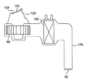
図1は、本発明に係るバッテリ冷却システムを搭載した自動車2を概略的に示している。自動車2は、駆動源として図示しないエンジンと電動モータを備え、エンジンと電動モータを切り替えて使用するか又は併用して走行する所謂ハイブリッド自動車(HEV:Hybrid Electric Vehicle)である。ただし、本発明は、ハイブリッド自動車以外の車両にも等しく適用できる。
[First Embodiment]
FIG. 1 schematically shows an automobile 2 equipped with a battery cooling system according to the present invention. The automobile 2 is a so-called hybrid electric vehicle (HEV) that includes an engine and an electric motor (not shown) as drive sources, and uses the engine and the electric motor by switching or running together. However, the present invention is equally applicable to vehicles other than hybrid vehicles.
図1に示すように、本実施形態において、バッテリ40は、ボディパネル4に囲まれた車室内空間6において後席12の下側に配設されたバッテリケース42に収容されている。なお、バッテリ40は、例えば上述の電動モータの駆動源として使用される。バッテリケース42の前部には、空気導入部としての内気導入ダクト44が接続されるか又は一体に設けられており、内気導入ダクト44を介して、バッテリケース42内の空間と車室内空間6とが連通している。バッテリケース42の後部には、空気排出部としての排気ダクト46が接続されるか又は一体に設けられている。排気ダクト46はボディパネル4を貫通して設けられており、排気ダクト46を介して、バッテリケース42内の空間と、ボディパネル4の外側の車外空間8とが連通している。例えば排気ダクト46の中間部には、バッテリファン48が設けられている。バッテリファン48が作動すると、車室内空間6からバッテリケース42内の空間を通って車外空間8に排出される気流が形成される。これにより、車室内空間6の空気が内気導入ダクト44を通してバッテリケース42内に導入されるため、空調された車室内空間6の空気を利用してバッテリ40を冷却できる。また、バッテリ40の冷却に利用されたバッテリケース42内の空気、及び/又はバッテリ40から発生したバッテリケース42内のガスは、排気ダクト46を通して車外空間8に排出できる。バッテリ40の例えば側面には、バッテリ40からのガス発生の有無を検出するガスセンサ50と、バッテリの温度を検出するバッテリ温度センサ52とが取り付けられている。
As shown in FIG. 1, in the present embodiment, the
なお、本発明において、バッテリ40の配置は特に限定されず、バッテリ40は、バッテリケース42の内部に車室内空間6の空気を導入可能とする任意の位置に設置することができる。
In the present invention, the arrangement of the
車室内空間6の所定箇所には、車室内空間6の空気の温度を検出する室内温度センサ32が設けられている。また、車外空間8の所定箇所には、車外空間8の空気の温度を検出する外気温度センサ34が設けられている。
An
自動車2の例えば前部には、車室内空間6の空調を行う空調装置20が設けられている。空調装置20は、車外空間8の空気を空調装置20に導入する外気導入モードと、車室内空間6の空気を空調装置20に導入する内気循環モードとの間で切り替え可能となっている。
An
空調装置20は、外気導入モードの際に外気を導入するための外気導入口22と、内気循環モードの際に車室内空間6の空気を導入するための内気導入口24とを備えている。また、空調装置20は、図1において図示された外気導入口22と内気導入口24に加えて、後述のリヤ空調用の外気導入口120と内気導入口124を備えている。
The
空調装置20は、空調装置20内で冷却又は加熱された空気を吹き出すための複数の吹き出し口26,28,30を備えている。具体的に、空調装置20は、車室内の前席側に配設された前席側吹き出し口として、例えば図示しないインストルメントパネルから前席10の乗員の上半身に向かって空気を吹き出すためのベント吹き出し口26と、前席10の乗員の足元に向かって空気を吹き出すためのヒート吹き出し口28と、前部ガラスの下側から上方へガラス面に沿うように空気を吹き出すためのデフロスタ吹き出し口30とを備えている。また、空調装置20は、図1において図示された吹き出し口26,28,30に加えて、後席12の乗員の上半身に向かって空気を吹き出すためのリヤベント吹き出し口62(図3参照)と、後席12の乗員の足元に向かって空気を吹き出すためのリヤヒート吹き出し口64(図2参照)とを備えている。
The
図2と図3を参照しながら、空調装置20のより具体的な構成について説明する。図2は、空調装置20のフロント空調(後述のリヤベント吹き出し口62以外の吹き出し口から空調風を吹き出す空調)の構成要素を示し、図3は、空調装置20のリヤ空調(後述のリヤベント吹き出し口62から空調風を吹き出す空調)の構成要素を示す。
A more specific configuration of the
図2に示すように、空調装置20は、外気導入口22と内気導入口24が形成されたメインダクト部70を有し、メインダクト部70からベントダクト部72、ヒートダクト部74、及びデフロスタダクト部76が分岐している。
As shown in FIG. 2, the
外気導入口22と内気導入口24は、互いに隣接してメインダクト部70の一端(図中左端)に設けられており、内外気切り替えダンパ80により選択的に塞がれるようにしてある。内外気切り替えダンパ80により外気導入口22が塞がれた状態においては内気導入口24からメインダクト部70に空気が導入され、内外気切り替えダンパ80により内気導入口24が塞がれた状態においては外気導入口22からメインダクト部70に空気が導入される。すなわち、内外気切り替えダンパ80は、外気導入モードと内気循環モードとの間で空調装置20の設定を切り替える空気導入モード切替手段として機能する。
The outside
メインダクト部70の内部には、メインダクト部70に空気を導入するフロントブロア90が、外気導入口22及び内気導入口24の近傍に設けられている。フロントブロア90が作動すると、外気導入口22又は内気導入口24からメインダクト部70に空気が導入され、メインダクト部70の一端(図中左端)から他端(図中右端)に向かって流れる空調風が生じる。
Inside the
空調風の流れ方向においてフロントブロア90の下流側には、空調風を冷却するエバポレータ92が設けられ、さらにエバポレータ92の下流側のミキシング室100には、空調風を加熱するヒータコア94が設けられている。ヒータコア94の前方には、ヒータコア94の前面(加熱面)を開閉するミキシングダンパ96が設けられている。図中の実線で示されるようにヒータコア94の前面がミキシングダンパ96により塞がれているとき、メインダクト部70内の空調風はヒータコア94により加熱されることなくミキシング室100を通過する。一方、図中の鎖線で示されるようにミキシングダンパ96が開いた状態、すなわちヒータコア94の前面が開放されているとき、メインダクト部70内の空調風はヒータコア94により加熱されてミキシング室100を通過する。
An
ベントダクト部72は、運転席側に配設された運転席側吹き出し口に導かれる第1のベントダクト部72aと、助手席側に配設された助手席側吹き出し口に導かれる第2のベントダクト部72bとに分岐している。具体的に、第1のベントダクト部72aの中間部と先端とに運転席側のベント吹き出し口26aが設けられ、第2のベントダクト部78bの中間部と先端とに助手席側のベント吹き出し口26bが設けられている。第1及び第2のベントダクト部72a,72bの基端には、それらのベントダクト部72a,72bを開閉可能なベントダンパ82a,82bがそれぞれ設けられており、ベントダンパ82a,82bの開度によって、ミキシング室100からベントダクト部72a,72bに流れ込む空調風の流量、すなわちベント吹き出し口26a,26bからの空気の吹き出し量が調整される。
The
同様に、ヒートダクト部74は、運転席側吹き出し口に導かれる第1のヒートダクト部74aと、助手席側吹き出し口に導かれる第2のヒートダクト部74bとに分岐している。具体的に、第1のヒートダクト部74aの中間部に運転席側のヒート吹き出し口28aが設けられている。さらに、第1のヒートダクト部74bの先端には運転席の後方席のリヤヒート吹き出し口64aが設けられている。同様に、第2のヒートダクト部74bの中間部に助手席側のヒート吹き出し口28bが設けられ、さらに第2のヒートダクト部74bの先端に助手席の後方席のリヤヒート吹き出し口64bが設けられている。第1及び第2のヒートダクト部74a,74bの基端には、それらのヒートダクト部74a,74bを開閉可能なヒートダンパ84a,84bがそれぞれ設けられており、ヒートダンパ84a,84bの開度によって、ミキシング室100からヒートダクト部74a,74bに流れ込む空調風の流量、すなわちヒート吹き出し口28a,28b及びリヤヒート吹き出し口64a,64bからの空気の吹き出し量が調整される。
Similarly, the
また、デフロスタダクト部76も、運転席側吹き出し口に導かれる第1のデフロスタダクト部76aと、助手席側吹き出し口に導かれる第2のデフロスタダクト部76bとに分岐している。具体的に、第1のデフロスタダクト部76aの中間部と先端に運転席側のデフロスタ吹き出し口26aが設けられ、第2のデフロスタダクト部76bの中間部と先端に助手席側のデフロスタ吹き出し口26bが設けられている。第1及び第2のデフロスタダクト部76a,76bの基端には、それらのデフロスタダクト部76a,76bを開閉可能なデフロスタダンパ86a,86bが設けられており、デフロスタダンパ86a,86bの開度によって、ミキシング室100からデフロスタダクト部76a,76bに流れ込む空調風の流量、すなわちデフロスタ吹き出し口26a,26bからの空気の吹き出し量が調整される。
Further, the
図3に示すように、空調装置20はリヤベントダクト部178を有する。リヤベントダクト部178の一端(図中左端)には、外気導入口120と内気導入口124が互いに隣接して設けられており、空気導入モード切替手段としての内外気切り替えダンパ180により選択的に塞がれるようにしてある。内外気切り替えダンパ180により外気導入口120が塞がれた状態においては内気導入口124からリヤベントダクト部178に空気が導入され、内外気切り替えダンパ180により内気導入口124が塞がれた状態においては外気導入口120からリヤベントダクト部178に空気が導入される。一方、リヤベントダクト部178の他端(図中右下端)にはリヤベント吹き出し口62が設けられている。
As shown in FIG. 3, the
リヤベントダクト部178の内部には、リヤベントダクト部178に空気を導入するリヤブロア98が、外気導入口120及び内気導入口124の近傍に設けられている。リヤブロア98が作動すると、外気導入口120又は内気導入口124からリヤベントダクト部178に空気が導入され、リヤベントダクト部178の一端(図中左端)から他端(図中右端)に向かって流れる空調風が生じる。空調風の流れ方向においてリヤブロア98の下流側には、空調風を冷却するエバポレータ192が設けられている。リヤベントダクト部178を流れる空調風の流量、すなわちリヤベント吹き出し口62からの空気の吹き出し量は、リヤブロア98の回転速度によって調整可能となっている。
A
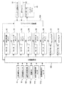
図4は、空調装置20とバッテリファン48の動作を制御するための構成を示すブロック図である。図4に示すように、空調装置20とバッテリファン48の動作を制御する制御手段は、空調装置20の動作を制御する空調制御部102と、バッテリファン48の動作を制御するバッテリファン制御部104とを有する。
FIG. 4 is a block diagram showing a configuration for controlling the operations of the
空調制御部102には、外気温度センサ34、室内温度センサ32、乗員が車室内温度を設定するために操作する温度設定操作部106、乗員が空調装置20を操作するための空調スイッチ108、助手席の乗員の有無を検知する助手席乗員検知センサ110、及び後席の乗員の有無を検知する後席乗員検知センサ112が電気的に接続されており、これらのセンサ等32,34,106,108,110,112から送られる信号が空調制御部102により受信されるようにしてある。
The air
また、空調制御部102には、内外気切り替えダンパ80を駆動するモータ81、ミキシングダンパ96を駆動するモータ97、ベントダンパ82を駆動するモータ83、ヒートダンパ84を駆動するモータ85、デフロスタダンパ86を駆動するモータ87、及びリヤベントダンパ88を駆動するモータ89が電気的に接続されており、空調制御部102から送られる制御信号により、上記各モータ81,83,85,87,89,91,97の駆動、すなわち、これらのモータにより駆動される各ダンパ80,82,84,86,88,90,96の動作が制御されるようにしてある。
The
さらに、空調制御部102には、フロントブロア90を駆動するブロアモータ91、及び、リヤブロア98を駆動するブロアモータ99が電気的に接続されており、空調制御部102から送られる制御信号により、ブロアモータ91,99の駆動、すなわち、これらのモータ91,99により駆動されるブロア90,98の動作が制御されるようにしてある。後述のバッテリ冷却制御が行われる場合を除いて、フロントブロア90はフロント空調の設定風量Vfsetと同量の空気を導入するように駆動され、リヤブロア98はリヤ空調の設定風量Vrsetと同量の空気を導入するように駆動される。以下の説明において、フロント空調の設定風量Vfsetにリヤ空調の設定風量Vrsetを加えた風量を、空調装置20の設定風量Vsetという。
Further, a
バッテリファン制御部104には、バッテリ温度センサ52とガスセンサ50が電気的に接続されており、これらのセンサ50,52から送られる信号がバッテリファン制御部104により受信されるようにしてある。また、バッテリファン制御部104には、バッテリファン48を駆動するモータ49が電気的に接続されており、バッテリファン制御部104から送られる制御信号により、モータ49の駆動、すなわちバッテリファン48の動作が制御されるようにしてある。バッテリファン48の動作は、バッテリ温度TBATに応じて制御される。バッテリファン48の風量は所定範囲内で制御可能であり、バッテリファン48の最小風量はVBAT2であり、最大風量はVBAT1である。バッテリファン48の最大風量VBAT1は、例えば40℃に上昇したバッテリ40を十分に冷却できる風量であり、空調装置20の設定風量Vsetの最大量よりも大きい量である。バッテリファン48は、原則としてバッテリ温度TBATに応じて予め決められた風量で駆動されるように制御されるが、後述のように所定条件下では異なる態様で制御される。
A
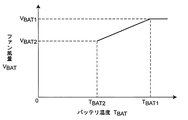
バッテリファン制御部104には、例えば図8に示すようなバッテリ温度TBATとバッテリファン48の風量VBATとの関係に関する所定のマップが予め記憶されている。図8に示すマップに基づいてバッテリファン48の駆動が制御される場合、バッテリ温度TBATが第1の温度TBAT1よりも高いときは、最大風量VBAT1でバッテリファン48が駆動され、バッテリ温度TBATが第2の温度TBAT2よりも高く第1の温度TBAT1以下である範囲内であるときは、バッテリ温度が高いときほど大きくなる風量VBAT(最小風量VBAT2〜最大風量VBAT1)でバッテリファン48が駆動され、バッテリ温度TBATが第2の温度TBAT2以下のときはバッテリファン48が駆動されない。
In the battery
空調制御部102とバッテリファン制御部104は電気的に接続されており、空調制御部102とバッテリファン制御部104との間で信号の送受信が可能となっている。
The air
かかる制御システムを用いた制御の具体例を、図5〜図9を参照しながら説明する。 A specific example of control using such a control system will be described with reference to FIGS.
〈バッテリファンの制御〉
先ず、図5を参照しながら、バッテリファン制御部104により行われるバッテリファン48の制御の処理の流れについて説明する。
<Battery fan control>
First, the flow of processing for controlling the
図5に示すように、先ずステップS11〜ステップS13では、バッテリ温度センサ52により検出された温度TBAT、ガスセンサ50により検出されたガス発生の有無、及び、空調制御部102から送信された空調装置20の設定風量Vsetの情報が読み込まれる。
As shown in FIG. 5, first, in step S11 to step S13, the temperature T BAT detected by the
続くステップS14では、ステップS12で読み込まれた情報に基づき、バッテリ40からガスが発生しているか否かが判断される。ステップS14において、ガスが発生していないと判断されるとステップS15に進み、ガスが発生していると判断されるとステップS19に進んで後述のようにバッテリファン48が最大風量VBAT1で駆動される。
In a succeeding step S14, it is determined whether or not gas is generated from the
ただし、本発明において、ガスの発生検知に関する処理(ステップS12及びステップS14の処理)は省略することも可能である。 However, in the present invention, the processing relating to gas generation detection (the processing in step S12 and step S14) can be omitted.
ステップS15では、ステップS11で読み込まれたバッテリ温度TBATが、予め設定された第1の温度TBAT1よりも高いか否かが判断される。第1の温度TBAT1は、バッテリ40を冷却するためにバッテリファン48を最大風量VBAT1で駆動する必要があるバッテリ40の温度の下限値であり、具体的には例えば40℃に設定される。
In step S15, it is determined whether or not the battery temperature T BAT read in step S11 is higher than a preset first temperature T BAT1 . The first temperature T BAT1 is a lower limit value of the temperature of the
ステップS15において、バッテリ温度TBATが第1の温度TBAT1以下であると判断されるとステップS16に進み、バッテリ温度TBATが第1の温度TBAT1よりも高いと判断されるとステップS19に進んで後述のようにバッテリファン48が最大風量VBAT1で駆動される。
If it is determined in step S15 that the battery temperature T BAT is equal to or lower than the first temperature T BAT1 , the process proceeds to step S16, and if it is determined that the battery temperature T BAT is higher than the first temperature T BAT1, the process proceeds to step S19. Then , as will be described later, the
ステップS16では、ステップS11で読み込まれたバッテリ温度TBATが、予め設定された第2の温度TBAT2よりも高いか否かが判断される。第2の温度TBAT2は、冷却が不要なバッテリ40の温度の上限値であり、具体的には例えば35℃に設定される。
In step S16, it is determined whether or not the battery temperature T BAT read in step S11 is higher than a preset second temperature T BAT2 . The second temperature T BAT2 is an upper limit value of the temperature of the
ステップS16において、バッテリ温度TBATが第2の温度TBAT2以下であると判断されると、バッテリ40の冷却が必要でないためステップS20に進んで、バッテリファン48が停止される。一方、ステップS16において、バッテリ温度TBATが第2の温度TBAT2よりも高いと判断されるとステップS17に進む。
If it is determined in step S16 that the battery temperature T BAT is equal to or lower than the second temperature T BAT2, it is not necessary to cool the
ステップS17では、空調制御部102から送られる信号に基づき、空調装置20がオンになっているか否かが判断される。ステップS17において、空調装置20がオンになっていると判断されるとステップS18に進み、空調装置20がオフになっていると判断されるとステップS21に進んで、例えば図8に示すマップに基づきバッテリ温度TBATに応じた風量でバッテリファン48が駆動される。
In step S17, based on the signal sent from the air
ステップS18では、空調装置20の設定風量Vsetと同じ量からなる基準量Vtarでバッテリファン48が駆動される。すなわち、バッテリファン48による排気量が設定風量Vsetと同じ量になる。ところで、ステップS18の処理が行われる際、空調装置20がオンである状態でバッテリファン48が作動するため、後述の空調装置20の制御により、空調装置20の空気導入モードが外気導入モードに設定される。外気導入モードの際、設定風量Vsetと同じ量の外気が空調装置20を通して車室内空間6に導入されるため、空調装置20による外気導入量とバッテリファン48による排気量とが等しくなる。よって、外気が空調装置20を通らずに車体の隙間等から車室内空間6に入り込むことを防止でき、空調効率を高めることができる。
In step S18, the
なお、本発明において、バッテリファン48の基準量Vtarは、必ずしも空調装置20の設定風量Vsetと同じ量である必要はなく、空調装置20が設定風量Vsetで作動しているときに外気が空調装置20を通らずに車室内空間6に入り込むことを防止できるような排気量に設定すればよい。具体的に、基準量Vtarは、例えば設定風量Vsetに所定値を加算して得られる量など、設定風量Vsetに所定の演算を行って得られる量であってもよい。また、ステップS18において、上記の処理(バッテリファン48の風量を基準量Vtarに設定する処理)に代えて、バッテリファン48の風量を基準量Vtarよりも小さい量に設定する処理を行うようにしてもよい。
In the present invention, the reference amount Vtar of the
ステップS19では、バッテリファン48が最大風量VBAT1で駆動される。これにより、バッテリ40を確実且つ迅速に冷却できるとともに、バッテリ40からガスが発生している場合はそのガスを確実且つ迅速に車外へ排出できる。上述したように、バッテリファン48の最大風量VBAT1は、空調装置20の設定風量Vsetの最大量よりも大きいため、ステップS19の処理により、バッテリファン48による排気量が、空調装置20の設定風量Vsetよりも大きくなる。しかし、このとき、後述のようにブロア90,98が例外的に制御されることにより(図7参照)、ブロア90,98による外気導入量Vc(フロントブロア90による外気導入量Vfcに、リヤブロア98による外気導入量Vrcを加えた量)が、設定風量Vsetよりも大きな量になるように増大されるため、外気が空調装置20を通らずに車室内空間6に入り込むことを防止できる。
In step S19, the
〈空調装置の制御〉
次に、図6を参照しながら、空調制御部102により行われる空調装置20の制御の処理の流れについて説明する。図6に示す制御は、空調装置20がオンになっていると判断されたときに実行される。
<Control of air conditioner>
Next, a flow of control processing of the
図6に示すように、先ずステップS31〜ステップS36では、種々の情報が読み込まれる。具体的には、外気温度センサ34により検出された温度Ta(ステップS31)、室内温度センサ32により検出された温度Tr(ステップS32)、温度設定操作部106の操作により設定された温度Tset(ステップS33)、外気温度Ta、室内温度Tr及び設定温度Tsetに基づき算出されるか又は乗員の操作により設定される設定風量Vset(ステップS34)、助手席乗員検知センサ110及び/又は後席乗員検知センサ112により検知された助手席及び/又は後席の乗員の有無(ステップS35)、及び、上述のように制御されたバッテリファン48の風量VBAT(ステップS36)が読み込まれる。ただし、第1の実施形態において、ステップS35の処理は省略可能である。
As shown in FIG. 6, first, in steps S31 to S36, various information is read. Specifically, the temperature Ta detected by the outside air temperature sensor 34 (step S31), the temperature Tr detected by the indoor temperature sensor 32 (step S32), and the temperature Tset set by the operation of the temperature setting operation unit 106 (step S33), the set air volume Vset calculated based on the outside air temperature Ta, the room temperature Tr, and the set temperature Tset or set by the occupant's operation (step S34), the passenger seat
続いて、ステップS37〜ステップS40では、種々の演算が行われる。具体的には、設定温度Tsetと設定風量Vsetに基づき吹き出し温度が演算され(ステップS37)、ブロア90,98を駆動するブロアモータ91,99に印加されるブロア電圧が後述の制御(図7参照)により演算され(ステップS38)、後述の制御(図9参照)により吹き出しモード(ベントモード、ヒートモード、又はデフロスタモード等)が演算され(ステップS39)、乗員の操作又はステップS36で読み込まれた情報(バッテリファン48の作動の有無)に基づき空気導入モードが演算される(ステップS40)。
Subsequently, in steps S37 to S40, various calculations are performed. Specifically, the blowout temperature is calculated based on the set temperature Tset and the set air volume Vset (step S37), and the blower voltage applied to the
ステップS40では、バッテリファン48が作動している場合、外気導入モードが選択される。これにより、空調装置20が作動している場合、空調装置20が外気導入モードに設定された状態で、上述のバッテリ冷却制御(図5のステップS18及びステップS19の制御)が行われるようにしてある。
In step S40, when the
続くステップS41〜ステップS45では、ステップS37〜ステップS40の演算の結果に基づき、種々の出力が行われる。具体的には、エバポレータ92の駆動が制御され(ステップS41)、ミキシングダンパ96の開度が調整され(ステップS42)、ブロア90,98の駆動が制御され(ステップS43)、吹き出し量を調整する各ダンパ82,84,86,88の開度が調整され(ステップS44)、内外気切り替えダンパ80,180が必要に応じて駆動される(ステップS45)。
In subsequent steps S41 to S45, various outputs are performed based on the results of the calculations in steps S37 to S40. Specifically, the driving of the
ステップS40においてバッテリファン48の作動の情報に基づき外気導入モードが選択された場合、ステップS45では、外気導入モードとなるように内外気切り替えダンパ80,180の駆動が制御される。
When the outside air introduction mode is selected based on the operation information of the
〈ブロアの制御〉
続いて、図7を参照しながら、空調制御部102により行われる空調装置20のブロア90,98の制御(図6のステップS38の制御)の処理の流れについて説明する。
<Blower control>
Next, the flow of processing for controlling the
図7に示すように、先ずステップS51では、上述のように制御されたバッテリファン48による排気量VBATが、上述の基準量Vtar(本実施形態では、図6のステップS34で読み込まれた空調装置20の設定風量Vsetと同じ量)よりも大きいか否かが判断される。
As shown in FIG. 7, first, in step S51, the exhaust amount V BAT by the
ステップS51において、バッテリファン48による排気量VBATが基準量Vtarよりも大きいと判断されると、ステップS52に進む。
In step S51, the exhaust amount V BAT by the
ステップS52では、ブロア90,98による外気導入量Vcが設定風量Vsetよりも大きな量に増大するようにブロア電圧が演算されて、図6に示す空調装置20の制御フローに戻る。具体的に、ステップS52では、外気導入量Vcがバッテリファン48による排気量VBATと同じ量になるようにブロア電圧が演算される。このようにして、ブロア90,98による外気導入量Vcとバッテリファン48による排気量VBATとが同量になるように制御することで、図5のステップS19のバッテリ冷却制御によりバッテリファン48の風量VBATが増大したときでも、外気が空調装置20を通らずに車室内空間6に入り込むことを防止でき、空調効率を良好に維持することができる。
In step S52, the blower voltage is calculated so that the outside air introduction amount Vc by the
ただし、ステップS52の処理は、外気導入量Vcを、必ずしも排気量VBATと同じ量になるように増大させる必要はなく、排気量VBATに所定の演算を行って得られる量になるように増大させるようにしてもよい。 However, the process of step S52, the outside air introduction amount Vc, it is not always necessary to increase to be the same amount as the displacement volume V BAT, so that the amount obtained by performing a predetermined operation on the exhaust amount V BAT You may make it increase.
一方、ステップS51において、バッテリファン48による排気量VBATが基準量Vtar以下であると判断された場合、ブロア90,98による外気導入量Vcを増大させる補正を行う必要がない。そのため、ステップS53に進んで、外気導入量Vcが設定風量Vsetになるようにブロア電圧が演算されて、図6に示す空調装置20の制御フローに戻る。
On the other hand, in step S51, if the exhaust amount V BAT by the
[第2の実施形態]
図9を参照しながら、本発明の第2の実施形態について説明する。第2の実施形態では、空調装置20の吹き出しモードが空調制御部102により後述のように制御されることで、バッテリ冷却制御に伴うブロア風量Vcの増大分(Vc−Vset)の空調風が乗員に直接当たることを回避できる。以下、具体的に説明する。
[Second Embodiment]
A second embodiment of the present invention will be described with reference to FIG. In the second embodiment, the air blower mode of the
図7に示すブロア90,98の制御(図6のステップS38の制御)において、ステップS52の処理を行うと、上述のようにブロア90,98による外気導入量(ブロア風量)Vcが増大する。ただし、このとき、第2の実施形態では、フロントブロア90による外気導入量(フロントブロア風量Vfc)のみが増大するように制御されるものとする。
In the control of the
外気導入量Vcの増大に伴い、各吹き出し口26,28,30,64からの空調風の吹き出し量が一律に増大すると、吹き出し量が増大した空調風が乗員に当たり、乗員に違和感や不快感を与える懸念がある。このような観点から、本実施形態では、バッテリ冷却制御に伴うブロア風量Vcの増大分(Vc−Vset)の空調風が乗員に直接当たらないように、吹き出しモードの制御が次のように行われる。
When the amount of air-conditioning air blown from each
〈吹き出しモードの制御〉
図9を参照しながら、空調装置20の吹き出しモードの制御(図6のステップS39の制御)の処理の流れについて説明する。
<Control of balloon mode>
With reference to FIG. 9, the flow of processing of the air blower mode control of the air conditioner 20 (control in step S39 in FIG. 6) will be described.
図9に示すように、先ずステップS61では、図6のステップS33で読み込まれた設定温度Tsetが、予め設定された温度TC1よりも高いか否かが判断される。 As shown in FIG. 9, first, in step S61, the set temperature Tset read in step S33 in FIG. 6, whether or not high is determined than the temperature T C1, which is set in advance.
ステップS61において、設定温度Tsetが温度TC1よりも高いと判断されると、ステップS65に進んで、ヒートモード(空調風をヒート吹き出し口28のみから吹き出させるモード)が選択されて、図6の制御フローに戻る。 In step S61, the set temperature Tset is determined to be higher than the temperature T C1, the process proceeds to step S65, heat mode (mode for blown from the air-conditioned air only heat outlet 28) is selected, in FIG. 6 Return to control flow.
一方、ステップS61において、設定温度Tsetが温度TC1以下であると判断されると、ステップS62に進んで、設定温度Tsetが、予め設定された温度TC2よりも高いか否かが判断される。ステップS62において、設定温度Tsetが温度TC2よりも高いと判断されるとステップS66に進み、設定温度Tsetが温度TC2よりも以下であると判断されるとステップS63に進む。 On the other hand, when it is determined in step S61 that the set temperature Tset is equal to or lower than the temperature T C1 , the process proceeds to step S62, and it is determined whether or not the set temperature Tset is higher than the preset temperature T C2. . In step S62, the process proceeds to the the Step S66 determines that higher than the temperature T C2 set temperature Tset, the set temperature Tset is determined to be less than the temperature T C2 proceeds to step S63.
ステップS63では、図7の制御(図6の制御のステップS38の処理)によりブロア風量Vcが増大するように制御されたか否かが判断される。 In step S63, it is determined whether or not the blower air volume Vc is controlled to increase by the control of FIG. 7 (the process of step S38 of FIG. 6).
ステップS63において、ブロア風量Vcが増大しないと判断されるとステップS69に進んで、通常のベントモード(空調風をベント吹き出し口26のみから吹き出させるモード)が選択されて、図6の制御フローに戻る。 If it is determined in step S63 that the blower air volume Vc does not increase, the process proceeds to step S69, where a normal vent mode (a mode in which the conditioned air is blown out only from the vent outlet 26) is selected, and the control flow of FIG. Return.
一方、ステップS63において、ブロア風量Vcが増大すると判断されるとステップS64に進んで、特別ベントモードが選択されて、図6の制御フローに戻る。ここでいう「特別ベントモード」とは、通常のベントモードと同じ量の空調風をベント吹き出し口26から吹き出させ、ブロア風量の増大分(Vc−Vset)の空調風をデフロスタ吹き出し口30から吹き出させるモードを指す。ステップS64では、特別ベントモードが選択されることにより、ブロア風量の増大分(Vc−Vset)の空調風がデフロスタ吹き出し口30から吹き出るため、乗員の上半身に当たる空調風の風量が増大せず、乗員に違和感や不快感を与えることを防止できる。
On the other hand, if it is determined in step S63 that the blower air volume Vc increases, the process proceeds to step S64, the special vent mode is selected, and the process returns to the control flow of FIG. Here, the “special vent mode” means that the same amount of conditioned air as in the normal vent mode is blown out from the
ただし、ステップS64の特別ベントモードでは、ブロア風量の増大分(Vc−Vset)の空調風がデフロスタ吹き出し口30から吹き出るようにしてあるが、ブロア風量の増大分(Vc−Vset)の一部又は全部の空調風を、ヒート吹き出し口28から吹き出
させるようにしてもよい。
However, in the special vent mode in step S64, the conditioned air corresponding to the increase in the blower air volume (Vc-Vset) is blown out from the
ステップS66では、ステップS63と同様、図7の制御(図6の制御のステップS38の処理)によりブロア風量Vcが増大するように制御されたか否かが判断される。 In step S66, as in step S63, it is determined whether or not the blower air volume Vc is controlled to increase by the control in FIG. 7 (the process in step S38 in FIG. 6).
ステップS66において、ブロア風量Vcが増大しないと判断されるとステップS68に進んで、通常のバイレベルモード(空調風をベント吹き出し口26とヒート吹き出し口28から吹き出させるモード)が選択されて、図6の制御フローに戻る。
If it is determined in step S66 that the blower air volume Vc does not increase, the process proceeds to step S68, where the normal bi-level mode (mode in which the conditioned air is blown out from the
一方、ステップS66において、ブロア風量Vcが増大すると判断されるとステップS67に進んで、特別バイレベルモードが選択されて、図6の制御フローに戻る。ここでいう「特別バイレベルモード」とは、通常のバイレベルモードと同じ量の空調風をベント吹き出し口26とヒート吹き出し口28とから吹き出させ、ブロア風量の増大分(Vc−Vset)の空調風をデフロスタ吹き出し口30から吹き出させるモードを指す。ステップS67では、特別バイレベルモードが選択されることにより、ブロア風量の増大分(Vc−Vset)の空調風がデフロスタ吹き出し口30から吹き出るため、乗員の上半身と足元に当たる空調風の風量が増大せず、乗員に違和感や不快感を与えることを防止できる。
On the other hand, if it is determined in step S66 that the blower air volume Vc increases, the process proceeds to step S67, the special bi-level mode is selected, and the control flow returns to FIG. Here, the “special bi-level mode” means that the same amount of air-conditioning air as in the normal bi-level mode is blown out from the
ただし、ステップS67の特別バイレベルモードでは、ブロア風量の増大分(Vc−Vset)の空調風がデフロスタ吹き出し口30から吹き出るようにしてあるが、ブロア風量の増大分(Vc−Vset)の一部又は全部の空調風を、ヒート吹き出し口28から吹き出る空調風に上乗せするようにしてもよい。この場合でも、乗員の上半身に当たる空調風は増大しないため、乗員に与える違和感や不快感を抑制できる。
However, in the special bi-level mode in step S67, the conditioned air corresponding to the increase in the blower air volume (Vc-Vset) is blown out from the
なお、吹き出しモードとしては、上述したモード以外にも種々のモード(空調風をデフロスタ吹き出し口30のみから吹き出させるモード等)が考えられるため、図9に示す制御フローには、上述したモード以外のモードを選択するための処理を適宜加えるようにしてもよい。また、第2の実施形態において、その他の構成は第1の実施形態と同様である。 Note that various modes other than the above-described modes (such as a mode in which the conditioned air is blown out only from the defroster outlet 30) can be considered as the blowing mode. Therefore, the control flow shown in FIG. You may make it add the process for selecting a mode suitably. In the second embodiment, other configurations are the same as those in the first embodiment.
[第3の実施形態]
図10を参照しながら、本発明の第3の実施形態について説明する。第3の実施形態では、バッテリ冷却制御に伴いブロア風量Vcが増大する場合において、ブロア風量Vcの増大分(Vc−Vset)の空調風が乗員に直接当たらないようにするための構成が第2の実施形態と異なっている。
[Third Embodiment]
A third embodiment of the present invention will be described with reference to FIG. In the third embodiment, when the blower air volume Vc increases with the battery cooling control, the configuration for preventing the conditioned air of the increased amount (Vc−Vset) of the blower air volume Vc from directly hitting the occupant is the second configuration. This is different from the embodiment.
第3の実施形態では、基本的には第1及び第2の実施形態と同様の制御が行われるが、空調装置20の吹き出しモードを演算する処理(図6の制御のステップS39の処理)の構成が第1及び第2の実施形態と異なる。第3の実施形態では、外気温度Ta、室内温度Tr及び設定温度Tsetに基づき吹き出しモードが選択され、ベントモードが選択される場合、これに続いて、図10に示すベントモード補正制御が行われる。 In the third embodiment, basically the same control as in the first and second embodiments is performed, but the process of calculating the blowing mode of the air conditioner 20 (the process in step S39 of the control in FIG. 6). The configuration is different from the first and second embodiments. In the third embodiment, when the blowing mode is selected based on the outside air temperature Ta, the room temperature Tr, and the set temperature Tset, and the vent mode is selected, the vent mode correction control shown in FIG. 10 is subsequently performed. .
〈ベントモード補正制御〉
図10を参照しながら、ベントモード補正制御の処理の流れについて説明する。
<Bent mode correction control>
The flow of the vent mode correction control process will be described with reference to FIG.
図10に示すように、先ずステップS71では、運転席側のベント吹き出し口26aと助手席側のベント吹き出し口26bとの間で吹き出し量差が設定されているか否かが判断される。
As shown in FIG. 10, first, in step S71, it is determined whether or not a blowing amount difference is set between the
ステップS71において、運転席側のベント吹き出し口26aと助手席側のベント吹き出し口26bとの間で吹き出し量差が設定されていると判断されると、ステップS76に進んで、設定された吹き出し量差となるようにベントダンパ82a,82bの開度が調整されるようにベントモードが補正されて、図6の制御フローに戻る。
If it is determined in step S71 that a difference in the amount of blowout is set between the
ステップS71において、運転席側のベント吹き出し口26aと助手席側のベント吹き出し口26bとの間で吹き出し量差が設定されていないと判断されると、ステップS72に進んで、図7の制御(図6の制御のステップS38の処理)によりブロア風量Vcが増大するように制御されたか否かが判断される。
If it is determined in step S71 that a difference in the amount of air blow is not set between the
ステップS72において、ブロア風量Vcが増大しないと判断されるとステップS75に進んで、補正されることなく通常のベントモード(設定風量Vfsetの空調風が均等に分散されて運転席側のベント吹き出し口26aと助手席側のベント吹き出し口26bとから吹き出るモード)が選択され、ステップS72において、ブロア風量Vcが増大すると判断されるとステップS73に進む。
If it is determined in step S72 that the blower air volume Vc does not increase, the process proceeds to step S75, and the normal vent mode (the conditioned air of the set air volume Vfset is evenly distributed without correction and the vent air outlet on the driver's seat side is corrected. 26a and the
ステップS73では、図6のステップS35において読み込まれた情報に基づき、助手席の乗員の有無が判断される。 In step S73, the presence or absence of a passenger in the passenger seat is determined based on the information read in step S35 of FIG.
ステップS73において、助手席に乗員がいると判断されるとステップS75に進んで、補正されることなく通常のベントモードが選択され、ステップS73において、助手席に乗員がいないと判断されるとステップS74に進む。 If it is determined in step S73 that there is an occupant in the passenger seat, the process proceeds to step S75, the normal vent mode is selected without correction, and if it is determined in step S73 that there is no occupant in the passenger seat, step Proceed to S74.
ステップS74では、ブロア風量の増大分(Vc−Vset)の空調風が、助手席側のベント吹き出し口26bから吹き出る空調風に上乗せされるようにベントモードが補正されて、図6の制御フローに戻る。このように乗員のいない助手席側においてのみ空調風が増大するようにベントモードを補正することで、ブロア風量Vcの増大により乗員に違和感や不快感を与えることを防止できる。
In step S74, the vent mode is corrected so that the conditioned air corresponding to the increase in the blower air volume (Vc−Vset) is added to the conditioned air blown out from the
[第4の実施形態]
図11と図12を参照しながら、本発明の第4の実施形態について説明する。第4の実施形態では、バッテリ冷却制御に伴いブロア風量Vcを増大させる構成、及び、ブロア風量Vcの増大分(Vc−Vset)の空調風が乗員に直接当たらないようにするための構成が第1及び第2の実施形態と異なっている。
[Fourth Embodiment]
A fourth embodiment of the present invention will be described with reference to FIGS. In the fourth embodiment, the configuration for increasing the blower air volume Vc in accordance with the battery cooling control and the configuration for preventing the conditioned air of the increased amount of the blower air volume Vc (Vc−Vset) from directly hitting the occupant are the first. This is different from the first and second embodiments.
第4の実施形態では、バッテリファン48の制御(図5参照)、及び空調装置20の制御(図6参照)は、基本的には第1の実施形態と同様に行われるが、空調装置20のブロア電圧を演算する処理(図6の制御のステップS38の処理)の構成が第1の実施形態と異なる。具体的に、第1の実施形態では、図7のフローチャートに示す流れでブロア電圧が演算されるが、第4の実施形態では、フロントブロア90のブロア電圧が、図12のフローチャートで示す流れで演算され、リヤブロア98のブロア電圧が、図11のフローチャートで示す流れで演算される。
In the fourth embodiment, the control of the battery fan 48 (see FIG. 5) and the control of the air conditioner 20 (see FIG. 6) are basically performed in the same manner as in the first embodiment. The configuration of the process of calculating the blower voltage (the process of step S38 of the control in FIG. 6) is different from that of the first embodiment. Specifically, in the first embodiment, the blower voltage is calculated according to the flow shown in the flowchart of FIG. 7, but in the fourth embodiment, the blower voltage of the
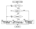
〈リヤブロアの制御〉
先ず、図11を参照しながら、リヤブロア98のブロア電圧を演算する処理の流れについて説明する。
<Rear blower control>
First, the flow of processing for calculating the blower voltage of the
図11に示すように、先ずステップS81では、リヤ空調(リヤベント吹き出し口62から空調風を吹き出す空調)がオンに設定されているか否かが判断される。ステップS81において、リヤ空調がオンに設定されていると判断されるとステップS86に進み、リヤ空調がオフに設定されていると判断されるとステップS82に進む。 As shown in FIG. 11, first, in step S81, it is determined whether or not rear air conditioning (air conditioning for blowing conditioned air from the rear vent outlet 62) is set to ON. If it is determined in step S81 that the rear air conditioning is set to ON, the process proceeds to step S86, and if it is determined that the rear air conditioning is set to OFF, the process proceeds to step S82.
ステップS82では、フロント空調(リヤベント吹き出し口62以外の吹き出し口から空調風を吹き出す空調)がオンに設定されているか否かが判断される。ステップS82において、フロント空調がオンに設定されていると判断されるとステップS83に進み、フロント空調がオフに設定されていると判断されると図6の制御フローに戻る。 In step S82, it is determined whether or not front air conditioning (air conditioning that blows conditioned air from an air outlet other than the rear vent outlet 62) is set to ON. If it is determined in step S82 that the front air conditioning is set to ON, the process proceeds to step S83, and if it is determined that the front air conditioning is set to OFF, the process returns to the control flow in FIG.
ステップS83では、図6のステップS35で読み込まれた情報に基づき、後席の乗員の有無が判断される。ステップS83において、後席に乗員がいないと判断されるとステップS84に進み、後席に乗員がいると判断されると図6の制御フローに戻る。 In step S83, the presence or absence of a passenger in the rear seat is determined based on the information read in step S35 of FIG. In step S83, if it is determined that there is no occupant in the rear seat, the process proceeds to step S84, and if it is determined that there is an occupant in the rear seat, the process returns to the control flow in FIG.
ステップS84では、図6のステップS36で読み込まれたバッテリファン48の風量VBATが上述の基準量Vtar(本実施形態では、図6のステップS34で読み込まれた空調装置20の設定風量Vsetと同じ量)よりも大きいか否かが判断される。ステップS84において、バッテリ風量VBATが基準量Vtarよりも大きいと判断されるとステップS85に進み、バッテリ風量VBATが基準量Vtar以下であると判断されるとステップS87に進む。
At step S84, the in air volume V BAT reference amount Vtar (present embodiment described above the
ステップS85では、バッテリ冷却制御に伴い必要となる外気導入量の増大分(VBAT−Vtar)の空調風がリヤベント吹き出し口62から吹き出されるように、リヤブロア98のブロア電圧が演算されて、図6の制御フローに戻る。これにより、リヤ空調がオフに設定されているにも拘わらず、増大分の空調風が、乗員がいない後席側に吹き出されるため、前席の乗員に違和感や不快感を与えることを防止できる。
In step S85, the blower voltage of the
ステップS86では、ステップS84と同様、図6のステップS36で読み込まれたバッテリファン48の風量VBATが基準量Vtarよりも大きいか否かが判断される。ステップS86において、バッテリ風量VBATが基準量Vtarよりも大きいと判断されるとステップS88に進み、バッテリ風量VBATが基準量Vtar以下であると判断されるとステップS87に進む。
In step S86, similarly to step S84, the whether the air volume V BAT of the
ステップS87では、空調装置20による外気導入量を増大させる必要がないため、要求された風量の空調風がリヤベント吹き出し口62から吹き出されるように、リヤブロア98のブロア電圧が演算されて、図6の制御フローに戻る。
In step S87, since it is not necessary to increase the amount of outside air introduced by the
ステップS88では、フロント空調がオンに設定されているか否かが判断される。ステップS88において、フロント空調がオンに設定されていると判断されるとステップS90に進み、フロント空調がオフに設定されていると判断されるとステップS89に進む。 In step S88, it is determined whether front air conditioning is set to ON. If it is determined in step S88 that the front air conditioning is set to ON, the process proceeds to step S90, and if it is determined that the front air conditioning is set to OFF, the process proceeds to step S89.
ステップS89では、バッテリ冷却制御に伴い必要となる外気導入量の増大分(VBAT−Vtar)が要求風量に加算されてなる風量の空調風が、リヤベント吹き出し口62から吹き出されるように、リヤブロア98のブロア電圧が演算されて、図6の制御フローに戻る。
In step S89, the
ステップS90では、外気導入量の増大分(VBAT−Vtar)の半分が要求風量に加算されてなる風量の空調風が、リヤベント吹き出し口62から吹き出されるように、リヤブロア98のブロア電圧が演算されて、図6の制御フローに戻る。外気導入量の増大分(VBAT−Vtar)の残りの半分は、後述のようにフロント空調の要求風量に加算され、これにより得られる量の空調風がフロント空調に利用される。
In step S90, the blower voltage of the
〈フロントブロアの制御〉
次に、図12を参照しながら、フロントブロア90のブロア電圧を演算する処理の流れについて説明する。
<Control of front blower>
Next, the flow of processing for calculating the blower voltage of the
図12に示すように、先ずステップS91では、図6のステップS36で読み込まれたバッテリファン48の風量VBATが基準量Vtarよりも大きいか否かが判断される。ステップS91において、バッテリ風量VBATが基準量Vtarよりも大きいと判断されるとステップS92に進み、バッテリ風量VBATが基準量Vtar以下であると判断されるとステップS94に進む。
As shown in FIG. 12, first, in step S91, the whether the air volume V BAT of the
ステップS92では、リヤ空調がオンに設定されているか否かが判断される。ステップS92において、リヤ空調がオンに設定されていると判断されるとステップS96に進み、リヤ空調がオフに設定されていると判断されるとステップS93に進む。 In step S92, it is determined whether or not the rear air conditioning is set to ON. In step S92, if it is determined that the rear air conditioning is set to ON, the process proceeds to step S96, and if it is determined that the rear air conditioning is set to OFF, the process proceeds to step S93.
ステップS93では、図6のステップS35で読み込まれた情報に基づき、後席の乗員の有無が判断される。ステップS93において、後席に乗員がいないと判断されるとステップS94に進み、後席に乗員がいると判断されるとステップS95に進む。 In step S93, the presence or absence of a passenger in the rear seat is determined based on the information read in step S35 of FIG. If it is determined in step S93 that there is no passenger in the rear seat, the process proceeds to step S94, and if it is determined that there is a passenger in the rear seat, the process proceeds to step S95.
ステップS94では、要求された風量の空調風がフロント空調の吹き出し口から吹き出されるように、フロントブロア90のブロア電圧が演算されて、図6の制御フローに戻る。このとき、バッテリ冷却制御に伴い外気導入量を増大させる必要がある場合、外気導入量の増大分(VBAT−Vtar)の空調風はリヤベント吹き出し口62から吹き出される。
In step S94, the blower voltage of the
ステップS95では、バッテリ冷却制御に伴い必要となる外気導入量の増大分(VBAT−Vtar)が要求風量に加算されてなる風量の空調風が、フロント空調の吹き出し口から吹き出されるように、フロントブロア90のブロア電圧が演算されて、図6の制御フローに戻る。
In step S95, the amount of conditioned air obtained by adding an increase in the amount of outside air necessary for battery cooling control (V BAT -Vtar) to the required amount of air is blown out from the front air conditioning outlet. The blower voltage of the
ステップS96では、外気導入量の増大分(VBAT−Vtar)の半分が要求風量に加算されてなる風量の空調風が、フロント空調の吹き出し口から吹き出されるように、フロントブロア90のブロア電圧が演算されて、図6の制御フローに戻る。外気導入量の増大分(VBAT−Vtar)の残りの半分は、上述のようにリヤ空調の要求風量に加算され、これにより得られる量の空調風がリヤ空調に利用される。
In step S96, the blower voltage of the
なお、フロント空調とリヤ空調がいずれもオンに設定されているとき、第4の実施形態では、後席の乗員の有無に関わらず、フロント空調の空調風とリヤ空調の空調風を、外気導入量の増大分(VBAT−Vtar)の半分ずつ増大させるようにしてあるが、後席に乗員がいないときは、外気導入量の増大分(VBAT−Vtar)の全部がリヤ空調の吹き出し口から吹き出るようにしてもよい。 In addition, when both the front air conditioning and the rear air conditioning are set to ON, in the fourth embodiment, the air conditioning wind of the front air conditioning and the air conditioning air of the rear air conditioning are introduced into the outside air regardless of the presence or absence of a passenger in the rear seat. The amount of increase in the amount (V BAT -Vtar) is increased by half, but when there is no occupant in the rear seat, the amount of increase in the outside air introduction amount (V BAT -Vtar) is entirely out of the rear air-conditioning outlet You may make it blow out.
[第5の実施形態]
図13を参照しながら、本発明の第5の実施形態について説明する。第5の実施形態では、第1〜第4の実施形態と異なり、空調装置20の風量に関係なくバッテリファン48が制御される。
[Fifth Embodiment]
A fifth embodiment of the present invention will be described with reference to FIG. In the fifth embodiment, unlike the first to fourth embodiments, the
〈バッテリファンの制御〉
第5の実施形態に係るバッテリファン48の制御の処理の流れについて説明する。第1〜第4の実施形態と同様、バッテリファン48は、バッテリファン制御部104により制御される。
<Battery fan control>
A flow of processing for controlling the
図13に示すように、先ずステップS101では、バッテリ温度センサ52により検出された温度TBATが読み込まれ、次のステップS102で、ガスセンサ50により検出されたガス発生の有無が読み込まれる。第5の実施形態では、空調装置20の風量に関係なくバッテリファン48が制御されるため、空調装置20の設定風量Vsetを読み込む処理を省略できる。
As shown in FIG. 13, first, in step S101, the temperature T BAT detected by the
続くステップS103では、ステップS102で読み込まれた情報に基づき、バッテリ40からガスが発生しているか否かが判断される。ステップS103において、ガスが発生していないと判断されるとステップS104に進み、ガスが発生していると判断されるとステップS107に進んでバッテリファン48が最大風量VBAT1で駆動される。
In a succeeding step S103, it is determined whether or not gas is generated from the
ただし、本発明において、ガスの発生検知に関する処理(ステップS102及びステップS103の処理)は省略することも可能である。 However, in the present invention, the processing relating to gas generation detection (the processing in steps S102 and S103) can be omitted.
ステップS104では、ステップS101で読み込まれたバッテリ温度TBATが、上述の第1の温度TBAT1(例えば40℃)よりも高いか否かが判断される。 In step S104, it is determined whether or not the battery temperature T BAT read in step S101 is higher than the above-described first temperature T BAT1 (for example, 40 ° C.).
ステップS104において、バッテリ温度TBATが第1の温度TBAT1以下であると判断されるとステップS105に進み、バッテリ温度TBATが第1の温度TBAT1よりも高いと判断されるとステップS107に進んでバッテリファン48が最大風量VBAT1で駆動される。
If it is determined in step S104 that the battery temperature T BAT is equal to or lower than the first temperature T BAT1 , the process proceeds to step S105, and if it is determined that the battery temperature T BAT is higher than the first temperature T BAT1 , the process proceeds to step S107. The
ステップS105では、ステップS101で読み込まれたバッテリ温度TBATが、上述の第2の温度TBAT2(例えば35℃)よりも高いか否かが判断される。 In step S105, it is determined whether or not the battery temperature T BAT read in step S101 is higher than the above-described second temperature T BAT2 (for example, 35 ° C.).
ステップS105において、バッテリ温度TBATが第2の温度TBAT2以下であると判断されると、バッテリ40の冷却が必要でないためステップS108に進んで、バッテリファン48が停止される。
If it is determined in step S105 that the battery temperature T BAT is equal to or lower than the second temperature T BAT2 , the
一方、ステップS105において、バッテリ温度TBATが第2の温度TBAT2よりも高いと判断されると、空調装置20がオンであるか否かの判定を行わずにステップS106に進んで、例えば図8に示すマップに基づきバッテリ温度TBATに応じた風量でバッテリファン48が駆動される。
On the other hand, if it is determined in step S105 that the battery temperature T BAT is higher than the second temperature T BAT2 , the process proceeds to step S106 without determining whether or not the
このように、第5の実施形態では、バッテリ40の温度が第2の温度TBAT2(例えば35℃)よりも高いとき、空調装置20がオンであるか否かに関わらず、バッテリファン48による排気量がバッテリ40の温度に応じた量となるようにバッテリファン48の動作が制御され(ステップS106)、この点で第1〜第4の実施形態と異なる。
As described above, in the fifth embodiment, when the temperature of the
そのため、仮に空調装置20を常に設定風量Vsetで作動させると、ステップS106の処理を行うことによりバッテリファン48による排気量VBATが空調装置20の外気導入量Vcよりも大きくなることがある。また、ステップS107においてバッテリファン48を最大風量VBAT1で駆動させる場合も同様である。バッテリファン48による排気量VBATが空調装置20の外気導入量Vcよりも大きくなると、空調効率が低下する懸念がある。そのため、第5の実施形態においても、第1〜第4の実施形態と同様、空調装置20が作動した状態でバッテリファン48が作動するとき、空調装置20の空気導入モードが外気導入モードに選択され、バッテリファンによる排気量VBATが上述の基準量Vtarよりも大きくなると、空調装置20の外気導入量Vcが設定風量Vsetよりも大きな量に増大するように制御される。また、この場合、外気導入量の増大分(Vc―Vset)の空調風が乗員に直接当たらないように空調装置20が制御され、これにより乗員に違和感や不快感を与えることを防止できる。
Therefore, if the
第5の実施形態において、空調装置20の外気導入量Vcを増大させるための具体的な構成、及び外気導入量の増大分(Vc―Vset)の空調風が乗員に直接当たらないようにするための具体的な構成としては、種々の構成を採用することができる。例えば、第2の実施形態と同様、図9に示す流れで吹き出しモードを制御することで外気導入量の増大分(Vc−Vset)の空調風を所定の吹き出し口から吹き出すようにしたり、第3の実施形態と同様、図10に示す流れでベントモード補正制御を行うことで、助手席に乗員がいない場合には外気導入量の増大分(Vc−Vset)の空調風を助手席側の吹き出し口から吹き出すようにしたり、第4の実施形態と同様、図11と図12に示す流れでブロア90,98を制御することで、後席に乗員がいない場合には外気導入量の増大分の空調風を後席側の吹き出し口から吹き出すようにしたりすることができる。
In the fifth embodiment, the specific configuration for increasing the outside air introduction amount Vc of the
[第6の実施形態]
図14と図15を参照しながら、本発明の第6の実施形態について説明する。バッテリ冷却制御に伴いバッテリファン48による排気量VBATが空調装置20の外気導入量Vcよりも大きくなったとき、第1〜第5の実施形態では、空調装置20の外気導入量Vcを増大させることで空調効率の低下を防止されるが、第6の実施形態は、空調装置20の外気導入量Vcを増大させなくても空調効率を良好に維持できる構成となっている。以下、第6の実施形態について具体的に説明する。
[Sixth Embodiment]
A sixth embodiment of the present invention will be described with reference to FIGS. 14 and 15. When the exhaust amount V BAT by the
図14に示すように、第6の実施形態では、車室内空間6を経由せずに直接的に外気をバッテリケース42内に導入するための外気導入部として、外気導入ダクト220が設けられている。具体的に、外気導入ダクト220は、バッテリケース42内の空間と車室内空間6とを連通する内気導入ダクト44から分岐して設けられている。外気導入ダクト220はボディパネル4を貫通して設けられ、外気導入ダクト220の先端が車外空間8に配置されている。これにより、車外空間8とバッテリケース42内の空間とが外気導入ダクト220を介して連通するようにしてある。内気導入ダクト44と外気導入ダクト220との合流部には、導入量調整手段としての調整ダンパ222が設けられている。
As shown in FIG. 14, in the sixth embodiment, an outside
調整ダンパ222を駆動する図示しないモータは、バッテリファン制御部104に電気的に接続されており、調整ダンパ222の開度が、バッテリファン制御部104により制御されるようにしてある。これにより、バッテリファン制御部104は、調整ダンパ222の開度を制御することで、外気導入ダクト220を介してバッテリケース42内の空間に導入される外気量を調整可能となっている。
A motor (not shown) that drives the
〈バッテリファンの制御〉
第6の実施形態において、バッテリファン48は、第1の実施形態のように空調装置20の設定風量(空調風量)Vcに応じた風量で駆動されるように制御してもよいし(図5参照)、第5の実施形態のように空調風量Vcに関係なく駆動されるように制御してもよい(図13参照)。
<Battery fan control>
In the sixth embodiment, the
〈調整ダンパの制御〉
次に、図15を参照しながら、調整ダンパ222の制御の処理の流れについて説明する。
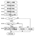
<Control of adjustment damper>
Next, the flow of control processing of the
図15に示すように、先ずステップS121〜ステップS124では、外気温度センサ34により検出された温度Ta、室内温度センサ32により検出された温度Tr、空調制御部102から送信された空調装置20の設定風量Vsetの情報、及びバッテリファン48の風量VBATが読み込まれる。
As shown in FIG. 15, first, in steps S <b> 121 to S <b> 124, the temperature Ta detected by the outside
続くステップS125では、ステップS122で読み込まれた室内温度Trが、ステップS121で読み込まれた外気温度Taよりも低いか否かが判断される。ステップS125において、室内温度Trが外気温度Ta以上であると判断されるとステップS129に進み、室内温度Trが外気温度Taよりも低いと判断されるとステップS126に進む。 In subsequent step S125, it is determined whether or not the room temperature Tr read in step S122 is lower than the outside air temperature Ta read in step S121. If it is determined in step S125 that the room temperature Tr is equal to or higher than the outside air temperature Ta, the process proceeds to step S129. If it is determined that the room temperature Tr is lower than the outside air temperature Ta, the process proceeds to step S126.
ステップS129では、車外空間8の外気のみがバッテリケース42内の空間に導入されるように調整ダンパ222の開度が調整される。これにより、車室内空間の空気よりも低温である外気を利用して、バッテリ40を効率的に冷却することができる。
In step S129, the opening degree of the
ステップS126では、バッテリファンの風量VBATが、ステップS123で読み込まれた空調風量Vcに基づき算出された上述の基準量Vtar(本実施形態では空調風量Vcと同じ量)よりも大きいか否かが判断される。ステップS126において、バッテリファンの風量VBATが空調風量Vc以下であると判断されるとステップS128に進み、バッテリファンの風量VBATが空調風量Vcよりも大きいと判断されるとステップS127に進む。 In step S126, the air volume V BAT of the battery fan, whether (in this embodiment the same amount as the conditioned air quantity Vc) loaded above the reference amount Vtar calculated on the basis of the conditioned air volume Vc greater than in step S123 is To be judged. If it is determined in step S126 that the air volume V BAT of the battery fan is equal to or less than the air conditioning air volume Vc, the process proceeds to step S128, and if it is determined that the air volume V BAT of the battery fan is greater than the air conditioning air volume Vc, the process proceeds to step S127.
ステップS128では、バッテリファン48による排気量VBATが基準量Vtar以下であり、バッテリケース42内への外気導入量を増大させる必要がないため、車室内空間6の空気のみがバッテリケース42内の空間に導入されるように調整ダンパ222の開度が調整される。
In step S128, the exhaust amount V BAT by the
ステップS127では、排気量VBATと基準量Vtarとの差(VBAT−Vtar)と同量の外気が外気導入ダクト220を通してバッテリケース42内に導入されるように、調整ダンパ222の開度が調整される。これにより、空調風量Vcを増大させなくても、バッテリケース42内への外気導入量を排気量VBATに応じて増大させることができる。よって、外気が空調装置20を通らずに車体の隙間等から車室内空間6に入り込むことを防止でき、空調効率を良好に維持することができる。
In step S127, the opening degree of the
ただし、本発明において、外気導入部及び導入量調整手段は上記構成に限定されるものではない。例えば、第6の実施形態では、外気導入部220が内気導入ダクト44から分岐して設けられているが、外気導入部は、バッテリケース42から直接延びるように設けてもよい。
However, in the present invention, the outside air introduction section and the introduction amount adjusting means are not limited to the above configuration. For example, in the sixth embodiment, the outside
以上、上述の実施形態を挙げて本発明を説明したが、本発明は上述の実施形態に限定されるものではない。 While the present invention has been described with reference to the above-described embodiment, the present invention is not limited to the above-described embodiment.
2:自動車、4:ボディパネル、6:車室内空間、8:車外空間、10:前席、12:後席、20:空調装置、22:外気導入口、24:内気導入口、26:ベント吹き出し口、28:ヒート吹き出し口、30:デフロスタ吹き出し口、32:室内温度センサ、34:外気温度センサ、40:バッテリ、42:バッテリケース、44。内気導入ダクト、46:排気ダクト、48:バッテリファン、50:ガスセンサ、52:バッテリ温度センサ、62:リヤベント吹き出し口、64:リヤヒート吹き出し口、80:内外気切り替えダンパ、90:フロントブロア、98:リヤブロア、102:空調制御部、104:バッテリファン制御部、110:助手席乗員検知センサ、112:後席乗員検知センサ。 2: automobile, 4: body panel, 6: vehicle interior space, 8: vehicle exterior space, 10: front seat, 12: rear seat, 20: air conditioner, 22: outside air inlet, 24: inside air inlet, 26: vent Outlet, 28: Heat outlet, 30: Defroster outlet, 32: Indoor temperature sensor, 34: Outside temperature sensor, 40: Battery, 42: Battery case, 44. Inside air introduction duct, 46: exhaust duct, 48: battery fan, 50: gas sensor, 52: battery temperature sensor, 62: rear vent outlet, 64: rear heat outlet, 80: inside / outside air switching damper, 90: front blower, 98: Rear blower 102: Air conditioning control unit 104: Battery fan control unit 110: Passenger seat occupant detection sensor 112: Rear seat occupant detection sensor
Claims (9)
該バッテリを収容するバッテリ収容部と、
該バッテリ収容部内の空間と車室内空間とを連通する空気導入部と、
前記バッテリ収容部内の空間と車外空間とを連通する空気排出部と、
前記空気導入部を通して車室内空間から前記バッテリ収容部内に空気を導入し、前記空気排出部を通して前記バッテリ収容部内から車外に空気を排出するバッテリファンと、
前記バッテリの温度を検出するバッテリ温度検出手段と、
車室内空間の空調を行う空調装置と、
該空調装置に設けられ、前記空調装置に空気を導入するブロアと、
前記空調装置に設けられ、車外空間の空気を前記空調装置に導入する外気導入モードと、車室内空間の空気を前記空調装置に導入する内気循環モードとの間で前記空調装置の設定を切り替える空気導入モード切替手段と、
前記空調装置の動作と前記バッテリファンの動作を制御する制御手段と、を備えた車両のバッテリ冷却システムであって、
前記制御手段は、
前記空調装置が作動した状態で前記バッテリファンを作動させるとき、前記外気導入モードが選択されるように前記空気導入モード切替手段を制御しながら、所定のバッテリ冷却制御を行い、
前記バッテリ冷却制御は、
前記バッテリ温度検出手段により検出された温度が所定温度以下であるとき、前記バッテリファンによる排気量が、前記空調装置の設定風量と同じ量又は前記設定風量を演算して得られる量からなる基準量以下となるように、前記バッテリファンの動作を制御し、
前記バッテリ温度検出手段により検出された温度が所定温度よりも高いとき、前記バッテリファンによる排気量が前記基準量よりも大きくなるように、前記バッテリファンの動作を制御するものである、ことを特徴とする車両のバッテリ冷却システム。 Battery,
A battery housing section for housing the battery;
An air introduction part for communicating the space in the battery housing part and the vehicle interior space;
An air discharge portion that communicates the space inside the battery housing portion and the space outside the vehicle;
A battery fan that introduces air from the vehicle interior space into the battery housing portion through the air introduction portion, and exhausts air from the battery housing portion to the outside of the vehicle through the air discharge portion;
Battery temperature detecting means for detecting the temperature of the battery;
An air conditioner for air conditioning the vehicle interior space;
A blower provided in the air conditioner for introducing air into the air conditioner;
Air that is provided in the air conditioner and switches the setting of the air conditioner between an outside air introduction mode that introduces air in the outside space into the air conditioner and an inside air circulation mode that introduces air in the vehicle interior space into the air conditioner. Introduction mode switching means;
A battery cooling system for a vehicle, comprising: control means for controlling the operation of the air conditioner and the operation of the battery fan;
The control means includes
When operating the battery fan in a state where the air conditioner is operating, performing a predetermined battery cooling control while controlling the air introduction mode switching means so that the outside air introduction mode is selected,
The battery cooling control is
When the temperature detected by the battery temperature detection means is equal to or lower than a predetermined temperature, the reference air amount is the same as the set air volume of the air conditioner or the amount obtained by calculating the set air volume. Control the operation of the battery fan so that
When the temperature detected by the battery temperature detecting means is higher than a predetermined temperature, the operation of the battery fan is controlled so that the exhaust amount by the battery fan becomes larger than the reference amount. Vehicle battery cooling system.
前記バッテリ冷却制御は、
前記バッテリ温度検出手段により検出された温度が所定温度以下であり、且つ、前記ガス検出手段によりガスが発生していないことが検出されたとき、前記バッテリファンによる排気量が前記基準量以下となるように、前記バッテリファンの動作を制御し、
前記バッテリ温度検出手段により検出された温度が所定温度よりも高いとき、及び/又は、前記ガス検出手段によりガスが発生したことが検出されたとき、前記バッテリファンによる排気量が前記基準量よりも大きくなるように、前記バッテリファンの動作を制御するものである、ことを特徴とする請求項1に記載の車両のバッテリ冷却システム。 The vehicle includes gas detection means for detecting the presence or absence of gas generation from the battery,
The battery cooling control is
When the temperature detected by the battery temperature detecting means is equal to or lower than a predetermined temperature and the gas detecting means detects that no gas is generated, the exhaust amount by the battery fan becomes equal to or lower than the reference amount. Control the operation of the battery fan,
When the temperature detected by the battery temperature detection means is higher than a predetermined temperature and / or when it is detected that gas is generated by the gas detection means, the exhaust amount by the battery fan is larger than the reference amount. The battery cooling system for a vehicle according to claim 1, wherein the operation of the battery fan is controlled to be large.
該バッテリを収容するバッテリ収容部と、
該バッテリ収容部内の空間と車室内空間とを連通する空気導入部と、
前記バッテリ収容部内の空間と車外空間とを連通する空気排出部と、
前記空気導入部を通して車室内空間から前記バッテリ収容部内に空気を導入し、前記空気排出部を通して前記バッテリ収容部内から車外に空気を排出するバッテリファンと、
前記バッテリの温度を検出するバッテリ温度検出手段と、
車室内空間の空調を行う空調装置と、
該空調装置に設けられ、前記空調装置に空気を導入するブロアと、
前記空調装置に設けられ、車外空間の空気を前記空調装置に導入する外気導入モードと、車室内空間の空気を前記空調装置に導入する内気循環モードとの間で前記空調装置の設定を切り替える空気導入モード切替手段と、
前記空調装置の動作と前記バッテリファンの動作を制御する制御手段と、を備え、
前記制御手段は、前記バッテリ温度検出手段により検出された温度が所定温度よりも高いとき前記バッテリファンによる排気量が前記バッテリの温度に応じた量となるように前記バッテリファンの動作を制御する、車両のバッテリ冷却システムであって、
前記制御手段は、
前記空調装置が作動した状態で前記バッテリファンを作動させるとき、前記外気導入モードが選択されるように前記空気導入モード切替手段を制御し、前記バッテリファンによる排気量が、前記空調装置の設定風量と同じ量又は前記設定風量を演算して得られる量からなる基準量よりも大きくなると、前記ブロアによる外気導入量を前記設定風量よりも大きな量に増大させる、ことを特徴とする車両のバッテリ冷却システム。 Battery,
A battery housing section for housing the battery;
An air introduction part for communicating the space in the battery housing part and the vehicle interior space;
An air discharge portion that communicates the space inside the battery housing portion and the space outside the vehicle;
A battery fan that introduces air from the vehicle interior space into the battery housing portion through the air introduction portion, and exhausts air from the battery housing portion to the outside of the vehicle through the air discharge portion;
Battery temperature detecting means for detecting the temperature of the battery;
An air conditioner for air conditioning the vehicle interior space;
A blower provided in the air conditioner for introducing air into the air conditioner;
Air that is provided in the air conditioner and switches the setting of the air conditioner between an outside air introduction mode that introduces air in the outside space into the air conditioner and an inside air circulation mode that introduces air in the vehicle interior space into the air conditioner. Introduction mode switching means;
Control means for controlling the operation of the air conditioner and the operation of the battery fan,
The control means controls the operation of the battery fan so that the amount of exhaust by the battery fan becomes an amount corresponding to the temperature of the battery when the temperature detected by the battery temperature detection means is higher than a predetermined temperature. A vehicle battery cooling system,
The control means includes
When the battery fan is operated in a state where the air conditioner is operated, the air introduction mode switching unit is controlled so that the outside air introduction mode is selected, and an exhaust amount by the battery fan is a set air volume of the air conditioner. Battery air cooling, wherein the amount of outside air introduced by the blower is increased to a larger amount than the set air volume when the air volume becomes larger than a reference amount consisting of the same amount or the amount obtained by calculating the set air volume. system.
前記制御手段は、前記ブロアによる外気導入量の前記増大分の空調風が前記別の吹き出し口から吹き出るように前記空調装置を制御する、ことを特徴とする請求項3または4に記載の車両のバッテリ冷却システム。 The vehicle includes a blowout port that blows conditioned air toward the passenger, and a blowout port that is different from the blowout port,
5. The vehicle according to claim 3, wherein the control unit controls the air conditioner so that the increased conditioned air of the outside air introduction amount by the blower blows out from the another outlet. Battery cooling system.
前記制御手段は、前記助手席乗員検知手段により助手席に乗員がいないことが検知されたとき、前記ブロアによる外気導入量の前記増大分の空調風が前記助手席側吹き出し口から吹き出るように前記空調装置を制御する、ことを特徴とする請求項3または4に記載の車両のバッテリ冷却システム。 The vehicle includes a driver's seat side outlet provided on the driver's seat side in the passenger compartment, a passenger's side outlet provided on the passenger's seat side in the passenger compartment, and an assistant for detecting the presence or absence of a passenger in the passenger seat. Seat occupant detection means,
The control means is configured such that when the passenger seat occupant detection means detects that no passenger is present in the passenger seat, the conditioned air for the increased amount of outside air introduced by the blower is blown out from the passenger seat side outlet. The vehicle battery cooling system according to claim 3 or 4, wherein the air conditioning device is controlled.
前記制御手段は、前記後席乗員検知手段により後席に乗員がいないことが検知されたとき、前記ブロアによる外気導入量の前記増大分の空調風が前記後席側吹き出し口から吹き出るように、前記空調装置を制御する、ことを特徴とする請求項3または4に記載の車両のバッテリ冷却システム。 The vehicle detects a front seat outlet provided on the front seat side of the passenger compartment, a rear outlet outlet provided on the rear seat side of the passenger compartment, and the presence or absence of a passenger in the rear seat. Seat occupant detection means,
When the control means detects that there is no occupant in the rear seat by the rear seat occupant detection means, the conditioned air for the increase in the amount of outside air introduced by the blower is blown out from the rear seat outlet. 5. The vehicle battery cooling system according to claim 3, wherein the air conditioner is controlled.
前記制御手段は、前記バッテリ冷却制御において前記バッテリファンによる排気量が前記基準量よりも大きくなるように前記バッテリファンを駆動させるとき、前記排気量と前記基準量との差と同量の外気が前記外気導入部を通して前記バッテリ収容部に導入されるように、前記導入量調整手段を制御する、ことを特徴とする請求項1または2に記載の車両のバッテリ冷却システム。 The vehicle has an outside air introduction part that communicates a space inside the battery housing part and a space outside the vehicle in order to introduce outside air directly into the battery accommodation part without passing through a vehicle interior space, and the outside through the outside air introduction part. An introduction amount adjusting means for adjusting an introduction amount of outside air introduced from the space into the battery housing portion;
In the battery cooling control, when the battery fan is driven so that an exhaust amount by the battery fan is larger than the reference amount in the battery cooling control, the same amount of outside air as the difference between the exhaust amount and the reference amount is generated. 3. The vehicle battery cooling system according to claim 1, wherein the introduction amount adjusting unit is controlled so as to be introduced into the battery housing unit through the outside air introduction unit. 4.
該バッテリを収容するバッテリ収容部と、
該バッテリ収容部内の空間と車室内空間とを連通する空気導入部と、
前記バッテリ収容部内の空間と車外空間とを連通する空気排出部と、
前記空気導入部を通して車室内空間から前記バッテリ収容部内に空気を導入し、前記空気排出部を通して前記バッテリ収容部内から車外に空気を排出するバッテリファンと、
前記バッテリの温度を検出するバッテリ温度検出手段と、
車室内空間の空調を行う空調装置と、
該空調装置に設けられ、前記空調装置に空気を導入するブロアと、
前記空調装置に設けられ、車外空間の空気を前記空調装置に導入する外気導入モードと、車室内空間の空気を前記空調装置に導入する内気循環モードとの間で前記空調装置の設定を切り替える空気導入モード切替手段と、
前記空調装置の動作と前記バッテリファンの動作を制御する制御手段と、を備え、
前記制御手段は、前記バッテリ温度検出手段により検出された温度が所定温度よりも高いとき前記バッテリファンによる排気量が前記バッテリの温度に応じた量となるように前記バッテリファンの動作を制御する、車両のバッテリ冷却システムであって、
前記車両は、車室内空間を経由せずに直接的に外気を前記バッテリ収容部内に導入するために前記バッテリ収容部内の空間と車外空間とを連通する外気導入部と、前記外気導入部を通して車外空間から前記バッテリ収容部に導入される外気の導入量を調整する導入量調整手段を備え、
前記制御手段は、
前記空調装置が作動した状態で前記バッテリファンを作動させるとき、前記外気導入モードが選択されるように前記空気導入モード切替手段を制御し、前記バッテリファンによる排気量が、前記設定風量と同じ量又は前記設定風量を演算して得られる量からなる基準量よりも大きくなると、前記排気量と前記基準量との差と同量の外気が前記外気導入部を通して前記バッテリ収容部に導入されるように、前記導入量調整手段を制御する、ことを特徴とする車両のバッテリ冷却システム。 Battery,
A battery housing section for housing the battery;
An air introduction part for communicating the space in the battery housing part and the vehicle interior space;
An air discharge portion that communicates the space inside the battery housing portion and the space outside the vehicle;
A battery fan that introduces air from the vehicle interior space into the battery housing portion through the air introduction portion, and exhausts air from the battery housing portion to the outside of the vehicle through the air discharge portion;
Battery temperature detecting means for detecting the temperature of the battery;
An air conditioner for air conditioning the vehicle interior space;
A blower provided in the air conditioner for introducing air into the air conditioner;
Air that is provided in the air conditioner and switches the setting of the air conditioner between an outside air introduction mode that introduces air in the outside space into the air conditioner and an inside air circulation mode that introduces air in the vehicle interior space into the air conditioner. Introduction mode switching means;
Control means for controlling the operation of the air conditioner and the operation of the battery fan,
The control means controls the operation of the battery fan so that the amount of exhaust by the battery fan becomes an amount corresponding to the temperature of the battery when the temperature detected by the battery temperature detection means is higher than a predetermined temperature. A vehicle battery cooling system,
The vehicle has an outside air introduction part that communicates a space inside the battery housing part and a space outside the vehicle in order to introduce outside air directly into the battery accommodation part without passing through a vehicle interior space, and the outside through the outside air introduction part. An introduction amount adjusting means for adjusting an introduction amount of outside air introduced from the space into the battery housing portion;
The control means includes
When operating the battery fan in a state where the air conditioner is operating, the air introduction mode switching means is controlled so that the outside air introduction mode is selected, and the amount of exhaust by the battery fan is the same amount as the set air volume Alternatively, when the air volume becomes larger than a reference amount that is obtained by calculating the set air volume, the same amount of outside air as the difference between the exhaust amount and the reference amount is introduced into the battery housing portion through the outside air introducing portion. And a battery cooling system for a vehicle, wherein the introduction amount adjusting means is controlled.
Priority Applications (1)
| Application Number | Priority Date | Filing Date | Title |
|---|---|---|---|
| JP2008201822A JP5217749B2 (en) | 2008-08-05 | 2008-08-05 | Vehicle battery cooling system |
Applications Claiming Priority (1)
| Application Number | Priority Date | Filing Date | Title |
|---|---|---|---|
| JP2008201822A JP5217749B2 (en) | 2008-08-05 | 2008-08-05 | Vehicle battery cooling system |
Publications (2)
| Publication Number | Publication Date |
|---|---|
| JP2010036723A true JP2010036723A (en) | 2010-02-18 |
| JP5217749B2 JP5217749B2 (en) | 2013-06-19 |
Family
ID=42009720
Family Applications (1)
| Application Number | Title | Priority Date | Filing Date |
|---|---|---|---|
| JP2008201822A Expired - Fee Related JP5217749B2 (en) | 2008-08-05 | 2008-08-05 | Vehicle battery cooling system |
Country Status (1)
| Country | Link |
|---|---|
| JP (1) | JP5217749B2 (en) |
Cited By (14)
| Publication number | Priority date | Publication date | Assignee | Title |
|---|---|---|---|---|
| CN101879859A (en) * | 2010-06-11 | 2010-11-10 | 奇瑞汽车股份有限公司 | Electric vehicle cooling system and control method thereof |
| JP2013184562A (en) * | 2012-03-07 | 2013-09-19 | Honda Motor Co Ltd | System and method for cooling high-voltage equipment of electric vehicle |
| JP2013230702A (en) * | 2012-03-26 | 2013-11-14 | Panasonic Corp | On-board air conditioning device, air conditioning unit, and vehicle |
| JP2014058254A (en) * | 2012-09-18 | 2014-04-03 | Mazda Motor Corp | Battery temperature regulator |
| JP2015085859A (en) * | 2013-10-31 | 2015-05-07 | トヨタ自動車株式会社 | Battery cooling structure |
| WO2015063555A1 (en) | 2013-10-31 | 2015-05-07 | Toyota Jidosha Kabushiki Kaisha | Battery cooling structure |
| CN105034745A (en) * | 2014-04-25 | 2015-11-11 | 丰田自动车株式会社 | Vehicle |
| US20180131052A1 (en) * | 2016-11-08 | 2018-05-10 | Ford Global Technologies, Llc | Battery thermal management systems for electrified vehicles |
| JP2019220440A (en) * | 2018-06-22 | 2019-12-26 | 株式会社Subaru | Battery pack housing structure |
| CN113386526A (en) * | 2021-07-30 | 2021-09-14 | 重庆长安新能源汽车科技有限公司 | Indirect heat pump air conditioning system, control method and pure electric vehicle |
| CN113386527A (en) * | 2021-07-30 | 2021-09-14 | 重庆长安新能源汽车科技有限公司 | Thermal management system and control method of pure electric vehicle and pure electric vehicle |
| CN113547890A (en) * | 2021-07-30 | 2021-10-26 | 重庆长安新能源汽车科技有限公司 | Thermal management system, thermal management system control method and automobile |
| CN113978200A (en) * | 2020-07-27 | 2022-01-28 | 丰田自动车株式会社 | Vehicle air conditioner |
| JP2022114092A (en) * | 2021-01-26 | 2022-08-05 | トヨタ自動車株式会社 | Vehicle battery control system |
Families Citing this family (1)
| Publication number | Priority date | Publication date | Assignee | Title |
|---|---|---|---|---|
| KR102181521B1 (en) * | 2016-03-03 | 2020-11-20 | 주식회사 엘지화학 | Cell module assembly improved in gas venting structure |
Citations (5)
| Publication number | Priority date | Publication date | Assignee | Title |
|---|---|---|---|---|
| JPH10306722A (en) * | 1997-03-05 | 1998-11-17 | Toyota Motor Corp | Vehicular battery cooling device |
| JP2001291532A (en) * | 2000-04-07 | 2001-10-19 | Fuji Heavy Ind Ltd | Battery temperature regulation device |
| JP2004268773A (en) * | 2003-03-10 | 2004-09-30 | Toyota Motor Corp | Air conditioner for vehicle |
| JP2006015862A (en) * | 2004-07-01 | 2006-01-19 | Nissan Motor Co Ltd | Battery cooling system for vehicle |
| JP2007137127A (en) * | 2005-11-15 | 2007-06-07 | Denso Corp | Battery cooling and air conditioning device for vehicle |
-
2008
- 2008-08-05 JP JP2008201822A patent/JP5217749B2/en not_active Expired - Fee Related
Patent Citations (5)
| Publication number | Priority date | Publication date | Assignee | Title |
|---|---|---|---|---|
| JPH10306722A (en) * | 1997-03-05 | 1998-11-17 | Toyota Motor Corp | Vehicular battery cooling device |
| JP2001291532A (en) * | 2000-04-07 | 2001-10-19 | Fuji Heavy Ind Ltd | Battery temperature regulation device |
| JP2004268773A (en) * | 2003-03-10 | 2004-09-30 | Toyota Motor Corp | Air conditioner for vehicle |
| JP2006015862A (en) * | 2004-07-01 | 2006-01-19 | Nissan Motor Co Ltd | Battery cooling system for vehicle |
| JP2007137127A (en) * | 2005-11-15 | 2007-06-07 | Denso Corp | Battery cooling and air conditioning device for vehicle |
Cited By (29)
| Publication number | Priority date | Publication date | Assignee | Title |
|---|---|---|---|---|
| CN101879859A (en) * | 2010-06-11 | 2010-11-10 | 奇瑞汽车股份有限公司 | Electric vehicle cooling system and control method thereof |
| JP2013184562A (en) * | 2012-03-07 | 2013-09-19 | Honda Motor Co Ltd | System and method for cooling high-voltage equipment of electric vehicle |
| US9517678B2 (en) | 2012-03-07 | 2016-12-13 | Honda Motor Co., Ltd. | High-voltage equipment cooling system for electric vehicle and high-voltage equipment cooling method for electric vehicle |
| US9878591B2 (en) | 2012-03-26 | 2018-01-30 | Panasonic Intellectual Property Management Co., Ltd. | Onboard air conditioning device, air conditioning unit, and vehicle |
| JP2013230702A (en) * | 2012-03-26 | 2013-11-14 | Panasonic Corp | On-board air conditioning device, air conditioning unit, and vehicle |
| JP2014058254A (en) * | 2012-09-18 | 2014-04-03 | Mazda Motor Corp | Battery temperature regulator |
| JP2015085859A (en) * | 2013-10-31 | 2015-05-07 | トヨタ自動車株式会社 | Battery cooling structure |
| WO2015063555A1 (en) | 2013-10-31 | 2015-05-07 | Toyota Jidosha Kabushiki Kaisha | Battery cooling structure |
| CN105659408B (en) * | 2013-10-31 | 2018-09-28 | 丰田自动车株式会社 | Battery cooling structure |
| CN105659408A (en) * | 2013-10-31 | 2016-06-08 | 丰田自动车株式会社 | Battery cooling structure |
| US9893395B2 (en) | 2013-10-31 | 2018-02-13 | Toyota Jidosha Kabushiki Kaisha | Battery cooling structure |
| CN105034745A (en) * | 2014-04-25 | 2015-11-11 | 丰田自动车株式会社 | Vehicle |
| US9365093B2 (en) | 2014-04-25 | 2016-06-14 | Toyota Jidosha Kabushiki Kaisha | Vehicle |
| JP2015209093A (en) * | 2014-04-25 | 2015-11-24 | トヨタ自動車株式会社 | vehicle |
| CN108075206A (en) * | 2016-11-08 | 2018-05-25 | 福特全球技术公司 | For the battery thermal management system of electric vehicle |
| US20180131052A1 (en) * | 2016-11-08 | 2018-05-10 | Ford Global Technologies, Llc | Battery thermal management systems for electrified vehicles |
| JP2019220440A (en) * | 2018-06-22 | 2019-12-26 | 株式会社Subaru | Battery pack housing structure |
| US10978754B2 (en) | 2018-06-22 | 2021-04-13 | Subaru Corporation | Battery-pack storage structure |
| JP7367629B2 (en) | 2020-07-27 | 2023-10-24 | トヨタ自動車株式会社 | Vehicle air conditioner |
| CN113978200A (en) * | 2020-07-27 | 2022-01-28 | 丰田自动车株式会社 | Vehicle air conditioner |
| JP2022023445A (en) * | 2020-07-27 | 2022-02-08 | トヨタ自動車株式会社 | Air conditioner for vehicle |
| US11794549B2 (en) | 2020-07-27 | 2023-10-24 | Toyota Jidosha Kabushiki Kaisha | Vehicle air-conditioner |
| JP2022114092A (en) * | 2021-01-26 | 2022-08-05 | トヨタ自動車株式会社 | Vehicle battery control system |
| JP7435489B2 (en) | 2021-01-26 | 2024-02-21 | トヨタ自動車株式会社 | Vehicle battery control system |
| CN113386526A (en) * | 2021-07-30 | 2021-09-14 | 重庆长安新能源汽车科技有限公司 | Indirect heat pump air conditioning system, control method and pure electric vehicle |
| CN113386526B (en) * | 2021-07-30 | 2022-06-14 | 重庆长安新能源汽车科技有限公司 | Indirect heat pump air conditioning system, control method and pure electric vehicle |
| CN113386527B (en) * | 2021-07-30 | 2022-05-03 | 重庆长安新能源汽车科技有限公司 | Thermal management system and control method of pure electric vehicle and pure electric vehicle |
| CN113547890A (en) * | 2021-07-30 | 2021-10-26 | 重庆长安新能源汽车科技有限公司 | Thermal management system, thermal management system control method and automobile |
| CN113386527A (en) * | 2021-07-30 | 2021-09-14 | 重庆长安新能源汽车科技有限公司 | Thermal management system and control method of pure electric vehicle and pure electric vehicle |
Also Published As
| Publication number | Publication date |
|---|---|
| JP5217749B2 (en) | 2013-06-19 |
Similar Documents
| Publication | Publication Date | Title |
|---|---|---|
| JP5217749B2 (en) | Vehicle battery cooling system | |
| US20120129439A1 (en) | Air conditioning system for vehicle | |
| JP2012136212A (en) | Vehicle air conditioner | |
| JP2004331024A (en) | Heating-element cooling device for vehicle | |
| JP3922195B2 (en) | Air conditioner for vehicles | |
| JPH1134637A (en) | Air conditioner for vehicle | |
| JP5018761B2 (en) | Air conditioner for vehicles | |
| JP2004114937A (en) | Air conditioner for vehicle | |
| JPH07251624A (en) | Air conditioner for vehicle | |
| JP3709689B2 (en) | Air conditioner for vehicles | |
| JP7031337B2 (en) | Vehicle air conditioner | |
| JP4055555B2 (en) | Air conditioner for vehicles | |
| JP5458663B2 (en) | Air conditioner for vehicles | |
| JP2006027518A (en) | Heating and cooling device for seat | |
| JP2009274573A (en) | Air conditioning device for vehicle | |
| JP4561303B2 (en) | Battery cooling device for vehicle | |
| JP5098940B2 (en) | Air conditioner for vehicles | |
| JP6390364B2 (en) | Air conditioner for vehicles | |
| JP2019098770A (en) | Air conditioning system | |
| JP4379203B2 (en) | Ventilator for vehicle | |
| JP3861805B2 (en) | Air conditioner for vehicles | |
| JP6647347B2 (en) | Vehicle air conditioner | |
| JP2009292385A (en) | Air conditioner for vehicle | |
| JPH05201240A (en) | Cabin ventilating structure for automobile | |
| JP4533166B2 (en) | Air conditioner for vehicles |
Legal Events
| Date | Code | Title | Description |
|---|---|---|---|
| A621 | Written request for application examination |
Free format text: JAPANESE INTERMEDIATE CODE: A621 Effective date: 20110620 |
|
| A521 | Request for written amendment filed |
Free format text: JAPANESE INTERMEDIATE CODE: A523 Effective date: 20120329 |
|
| A131 | Notification of reasons for refusal |
Free format text: JAPANESE INTERMEDIATE CODE: A131 Effective date: 20120821 |
|
| A977 | Report on retrieval |
Free format text: JAPANESE INTERMEDIATE CODE: A971007 Effective date: 20120823 |
|
| A521 | Request for written amendment filed |
Free format text: JAPANESE INTERMEDIATE CODE: A523 Effective date: 20121016 |
|
| TRDD | Decision of grant or rejection written | ||
| A01 | Written decision to grant a patent or to grant a registration (utility model) |
Free format text: JAPANESE INTERMEDIATE CODE: A01 Effective date: 20130205 |
|
| A61 | First payment of annual fees (during grant procedure) |
Free format text: JAPANESE INTERMEDIATE CODE: A61 Effective date: 20130218 |
|
| FPAY | Renewal fee payment (event date is renewal date of database) |
Free format text: PAYMENT UNTIL: 20160315 Year of fee payment: 3 |
|
| R150 | Certificate of patent or registration of utility model |
Ref document number: 5217749 Country of ref document: JP Free format text: JAPANESE INTERMEDIATE CODE: R150 Free format text: JAPANESE INTERMEDIATE CODE: R150 |
|
| LAPS | Cancellation because of no payment of annual fees |