JP2010036654A - Slide door device of aircraft - Google Patents
Slide door device of aircraft Download PDFInfo
- Publication number
- JP2010036654A JP2010036654A JP2008199836A JP2008199836A JP2010036654A JP 2010036654 A JP2010036654 A JP 2010036654A JP 2008199836 A JP2008199836 A JP 2008199836A JP 2008199836 A JP2008199836 A JP 2008199836A JP 2010036654 A JP2010036654 A JP 2010036654A
- Authority
- JP
- Japan
- Prior art keywords
- guide rail
- arm
- door
- slide door
- guide roller
- Prior art date
- Legal status (The legal status is an assumption and is not a legal conclusion. Google has not performed a legal analysis and makes no representation as to the accuracy of the status listed.)
- Granted
Links
- 230000006866 deterioration Effects 0.000 abstract 1
- 238000000034 method Methods 0.000 description 5
- 238000010586 diagram Methods 0.000 description 3
- 239000013598 vector Substances 0.000 description 2
- 230000008014 freezing Effects 0.000 description 1
- 238000007710 freezing Methods 0.000 description 1
- 230000002452 interceptive effect Effects 0.000 description 1
- 230000002093 peripheral effect Effects 0.000 description 1
Images


Classifications
-
- B—PERFORMING OPERATIONS; TRANSPORTING
- B64—AIRCRAFT; AVIATION; COSMONAUTICS
- B64C—AEROPLANES; HELICOPTERS
- B64C1/00—Fuselages; Constructional features common to fuselages, wings, stabilising surfaces or the like
- B64C1/14—Windows; Doors; Hatch covers or access panels; Surrounding frame structures; Canopies; Windscreens accessories therefor, e.g. pressure sensors, water deflectors, hinges, seals, handles, latches, windscreen wipers
- B64C1/1407—Doors; surrounding frames
- B64C1/1423—Passenger doors
- B64C1/1438—Passenger doors of the sliding type
-
- E—FIXED CONSTRUCTIONS
- E05—LOCKS; KEYS; WINDOW OR DOOR FITTINGS; SAFES
- E05D—HINGES OR SUSPENSION DEVICES FOR DOORS, WINDOWS OR WINGS
- E05D15/00—Suspension arrangements for wings
- E05D15/06—Suspension arrangements for wings for wings sliding horizontally more or less in their own plane
- E05D15/10—Suspension arrangements for wings for wings sliding horizontally more or less in their own plane movable out of one plane into a second parallel plane
- E05D15/1042—Suspension arrangements for wings for wings sliding horizontally more or less in their own plane movable out of one plane into a second parallel plane with transversely moving carriage
- E05D2015/1055—Suspension arrangements for wings for wings sliding horizontally more or less in their own plane movable out of one plane into a second parallel plane with transversely moving carriage with slanted or curved track sections or cams
-
- E—FIXED CONSTRUCTIONS
- E05—LOCKS; KEYS; WINDOW OR DOOR FITTINGS; SAFES
- E05Y—INDEXING SCHEME ASSOCIATED WITH SUBCLASSES E05D AND E05F, RELATING TO CONSTRUCTION ELEMENTS, ELECTRIC CONTROL, POWER SUPPLY, POWER SIGNAL OR TRANSMISSION, USER INTERFACES, MOUNTING OR COUPLING, DETAILS, ACCESSORIES, AUXILIARY OPERATIONS NOT OTHERWISE PROVIDED FOR, APPLICATION THEREOF
- E05Y2900/00—Application of doors, windows, wings or fittings thereof
- E05Y2900/50—Application of doors, windows, wings or fittings thereof for vehicles
- E05Y2900/502—Application of doors, windows, wings or fittings thereof for vehicles for aircraft or spacecraft
Abstract
Description
本発明は、航空機の胴体に形成したドア開口を開閉するスライドドア装置に関する。 The present invention relates to a slide door device that opens and closes a door opening formed in an aircraft fuselage.
航空機の胴体内に設けた貨物室のドア開口を開閉するスライドドアを案内すべく、ドア開口の上縁に沿って設けられた上部ガイドレールと、ドア開口の下縁に設けられた下部ガイドレールと、胴体の外表面に沿って設けられた中央ガイドレールとを備え、機体外側にせり出したスライドドアを前記3本のガイドレールに沿って胴体の外表面に沿ってスライドさせるスライドドア装置が、下記特許文献1により公知である。
ところで、上記従来のものは、胴体の外表面に沿ってガイドレールが配置されるため、ガイドレールによって空気抵抗が増加する問題があるだけでな、ガイドレールの氷結等によってスライドドアのスムーズな開閉ができなくなる可能性があった。 By the way, in the above-mentioned conventional one, since the guide rail is arranged along the outer surface of the fuselage, there is not only a problem that the air resistance is increased by the guide rail, but the sliding door can be smoothly opened and closed by freezing of the guide rail or the like. Could become impossible.
本発明は前述の事情に鑑みてなされたもので、スライドドアのスライドを案内するガイドレールを胴体の外表面から廃止して空気抵抗の低減や信頼性の向上を図ることを目的とする。 The present invention has been made in view of the above circumstances, and an object thereof is to eliminate the guide rail for guiding the slide of the slide door from the outer surface of the fuselage to reduce air resistance and improve reliability.
上記目的を達成するために、請求項1に記載された発明によれば、航空機の胴体に形成したドア開口を開閉するスライドドア装置において、前記ドア開口の上縁および下縁に沿ってそれぞれ固定した上部ガイドレールおよび下部ガイドレールに、スライドドアの上部に設けた上部アームの先端の上部ガイドローラと、スライドドアの下部に設けた下部アームの先端の下部ガイドローラとをそれぞれ転動可能に係合させるとともに、前記スライドドアの内面に固定した中間ガイドレールに、前記ドア開口に設けた中間アームの先端に設けた中間ガイドローラを転動可能に係合させることを特徴とする航空機のスライドドア装置が提案される。 To achieve the above object, according to the first aspect of the present invention, in the sliding door device that opens and closes the door opening formed in the fuselage of the aircraft, the door opening is fixed along the upper edge and the lower edge, respectively. An upper guide roller at the tip of the upper arm provided at the upper part of the slide door and a lower guide roller at the tip of the lower arm provided at the lower part of the slide door are respectively associated with the upper guide rail and the lower guide rail so that they can roll. And an intermediate guide roller provided at the tip of an intermediate arm provided in the door opening is slidably engaged with an intermediate guide rail fixed to the inner surface of the slide door. A device is proposed.
また請求項2に記載された発明によれば、請求項1の構成に加えて、前記上部ガイドレールおよび前記下部ガイドレールの一方を主ガイドレールとして他方を副ガイドレールとし、前記主ガイドレールを上下方向に平行移動した仮想的なガイドレールを仮想ガイドレールと定義し、前記副ガイドレールに対応するアームの先端に支軸部を介してスライダを枢支し、前記スライダに設けた複数のガイドローラを前記副ガイドレールに転動可能に係合させ、前記副ガイドレールの形状は、前記スライダに設けた複数のガイドローラを前記副ガイドレールに沿って転動させたときに、前記スライダの支軸部の移動軌跡が前記仮想ガイドレールに一致するように定められることを特徴とする航空機のスライドドア装置が提案される。
According to the invention described in
また請求項3に記載された発明によれば、請求項1または請求項2の構成に加えて、前記上部アーム、前記下部アームおよび前記中間アームの少なくとも一つは、上下軸まわりに回転自在に支持された第1ガイドローラと、水平軸まわりに回転自在に支持された第2ガイドローラとを備え、前記第1ガイドローラで前記スライドドアの移動を案内するとともに、前記第2ガイドローラで前記スライドドアの重量を支持し、前記少なくとも一つのアームに対応するガイドレールは、前記第1ガイドローラが嵌合する第1溝部と前記第2ガイドローラが嵌合する第2溝部とを上下2段に備えることを特徴とする航空機のスライドドア装置が提案される。 According to a third aspect of the present invention, in addition to the configuration of the first or second aspect, at least one of the upper arm, the lower arm, and the intermediate arm is rotatable about a vertical axis. A first guide roller supported; and a second guide roller supported rotatably about a horizontal axis. The first guide roller guides the movement of the slide door, and the second guide roller The guide rail that supports the weight of the sliding door and that corresponds to the at least one arm has a first groove portion into which the first guide roller is fitted and a second groove portion into which the second guide roller is fitted. A sliding door device for an aircraft is proposed.
尚、実施の形態の上部ガイドレール19は本発明の主ガイドレールに対応し、実施の形態の下部ガイドレール20は本発明の副ガイドレールあるいはガイドレールに対応し、実施の形態のボールジョイント45は本発明の支持部に対応し、実施の形態のピン47は本発明の上下軸に対応し、実施の形態の第1下部ガイドローラ48は本発明の第1ガイドローラ、下部ガイドローラあるいはガイドローラに対応し、実施の形態のピン49は本発明の水平軸に対応し、実施の形態の第2下部ガイドローラ50は本発明の第2ガイドローラ、下部ガイドローラあるいはガイドローラに対応する。
The
請求項1の構成によれば、航空機の胴体に形成したドア開口の上縁および下縁に沿ってそれぞれ固定した上部ガイドレールおよび下部ガイドレールに、スライドドアの上部に設けた上部アームの先端の上部ガイドローラと、スライドドアの下部に設けた下部アームの先端の下部ガイドローラとをそれぞれ転動可能に係合させ、スライドドアの内面に固定した中間ガイドレールに、ドア開口に設けた中間アームの先端に設けた中間ガイドローラを転動可能に係合させたので、上部ガイドレール、下部ガイドレールおよび中間ガイドレールでスライドドアをスムーズに案内しながら、胴体の外表面に中間ガイドレールが露出しないようにして空気抵抗の増加や信頼性の低下を防止することができる。 According to the configuration of claim 1, the upper guide rail and the lower guide rail fixed along the upper edge and the lower edge of the door opening formed in the fuselage of the aircraft, respectively, An intermediate arm provided at the door opening on an intermediate guide rail fixed to the inner surface of the slide door, with the upper guide roller and a lower guide roller at the tip of the lower arm provided at the lower part of the slide door engaged with each other in a rollable manner. The intermediate guide roller provided at the tip of the body is slidably engaged with the upper guide rail, the lower guide rail, and the intermediate guide rail, and the intermediate guide rail is exposed on the outer surface of the fuselage while smoothly guiding the sliding door. Thus, an increase in air resistance and a decrease in reliability can be prevented.
また請求項2に記載された発明によれば、上部ガイドレールおよび下部ガイドレールの一方を主ガイドレールとして他方を副ガイドレールとし、主ガイドレールを上下方向に平行移動した仮想的なガイドレールを仮想ガイドレールと定義する。副ガイドレールに対応するアームの先端に支軸部を介してスライダを枢支し、スライダに設けた複数のガイドローラを副ガイドレールに転動可能に係合させ、副ガイドレールの形状を、スライダに設けた複数のガイドローラを副ガイドレールに沿って転動させたときに、スライダの支軸部の移動軌跡が仮想ガイドレールに一致するように定めたので、スライドドアは実質的に同一形状で相互に平行移動した位置関係にある主ガイドレールと仮想ガイドレールとに案内され、スムーズに開閉することができる。仮想ガイドレールの代わりに実際にスライドドアのスライダを案内する副ガイドレールの形状は、スライダの形状、つまり複数のガイドローラと支持部との位置関係に応じて仮想ガイドレールと異なる形状にできるため、仮想ガイドレールが胴体の外表面から外側に張り出すような場合でも、副ガイドレールを胴体の外表面から外側に張り出さないように配置し、空気抵抗の増加および信頼性の低下を防止しながらスライドドアのスムーズな開閉を可能にすることができる。
According to the invention described in
また請求項3の構成によれば、上部アーム、下部アームおよび中間アームの少なくとも一つに、上下軸まわりに回転自在に支持されてスライドドアの移動を案内する第1ガイドローラと、水平軸まわりに回転自在に支持されてスライドドアの重量を支持する第2ガイドローラとを設け、対応するガイドレールに、第1ガイドローラが嵌合する第1溝部と第2ガイドローラが嵌合する第2溝部とを上下2段に設けたので、コンパクトな構造でスライドドアの案内と重量の支持とを両立させることができる。 According to the third aspect of the present invention, the at least one of the upper arm, the lower arm, and the intermediate arm is supported rotatably around the vertical axis and guides the movement of the slide door, and the horizontal axis. A second guide roller that is rotatably supported by the first guide roller and supports the weight of the slide door, and a second groove in which the first guide roller and the second guide roller are fitted to the corresponding guide rail. Since the groove portion is provided in two upper and lower stages, it is possible to achieve both sliding door guidance and weight support with a compact structure.
以下、本発明の実施の形態を添付の図面に基づいて説明する。 Hereinafter, embodiments of the present invention will be described with reference to the accompanying drawings.
図1〜図11は本発明の実施の形態を示すもので、図1飛行機の胴体後部の左側面の斜視図、図2は図1の2方向矢視図(スライドドアの内面の斜視図)、図3は前記図2においてドア開口部からスライドドアを分離した状態を示す斜視図、図4は図2の4方向拡大矢視図、図5は図2の5方向拡大矢視図、図6は図2の6部拡大図、図7は図2の7方向矢視図、図8はスライドドアの開工程の説明図(その1)、図9はスライドドアの開工程の説明図(その2)、図10はスライドドアの開工程の説明図(その3)、図11は上部・下部ガイドレールとスライドドアとの関係を示す図である。
1 to 11 show an embodiment of the present invention. FIG. 1 is a perspective view of a left side of a rear portion of a fuselage of an airplane, and FIG. 2 is a view in the direction of the arrow in FIG. 1 (perspective view of an inner surface of a slide door). 3 is a perspective view showing a state in which the slide door is separated from the door opening in FIG. 2, FIG. 4 is a four-direction enlarged arrow view of FIG. 2, FIG. 5 is a five-direction enlarged arrow view of FIG. 6 is an enlarged view of 6 parts of FIG. 2, FIG. 7 is a view taken in the direction of the
図1に示すように、飛行機の後部胴体11のフレーム12は、前後方向に所定間隔で配置された環状を成す複数のリングフレーム13…と、前後方向に概ね直線状に延びる複数のストリンガー14…とを結合して構成されており、3個のリングフレーム13…と5本のストリンガー14…とに囲まれた領域で、1個のリングフレーム13および3本のストリンガー14…を切り欠くことで、胴体11の内部の貨物室を開閉するスライドドア15のドア開口16が形成される。複数のリングフレーム13…の直径はテール側のものほど小径になっており、従って胴体11の表面形状は円筒面ではなく、円錐面に近い三次元曲面になっている。
As shown in FIG. 1, the
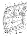
図2および図3から明らかなように、2個のリングフレーム13,13と2本のストリンガー14,14とに囲まれたドア開口16に、角を丸めた四角形状のドア開口フレーム17が4個のブラケット18…を介して2個のリングフレーム13,13に固定される。ドア開口フレーム17の上縁に沿うように、上部ガイドレール19が上側のストリンガー14に固定されるとともに、ドア開口フレーム17の下縁に沿うように、下部ガイドレール20が下側のストリンガー14に固定される。上部ガイドレール19および下部ガイドレール20は、胴体11の外部に露出しないようにドア開口フレーム17よりも機内側に配置されており、かつそれらのテール側の端部に機内側に湾曲する湾曲部19a,20aが形成される。ドア開口フレーム17のノーズ側の辺に沿うリングフレーム13にブラケット21が固定されており、このブラケット21に上下方向に延びるピン22を介して中間アーム23の基端が枢支される。
As apparent from FIGS. 2 and 3, there are four door
スライドドア15は、ドア開口フレーム17と略同形のドアフレーム24と、ドアフレーム24の外面を覆うドアスキン25と、ドアスキン25の内面に前後方向に固定され、前記中間アーム23の先端を案内する中間ガイドレール26とを備える。スライドドア15を閉じた状態では、ドアスキン25と胴体11のスキンとが滑らかに連続するとともに、ドアスキン25の外周部内面に設けたシール部材25aがドア開口フレーム17に当接する。ドアフレーム24のテール側の上端には上部アーム27の基端が固定されており、この上部アーム27の先端が前記上部ガイドレール19に案内される。またドアフレーム24のテール側の下端には下部アーム28の基端が固定されており、この下部アーム28の先端が前記下部ガイドレール20に案内される。中間ガイドレール26のノーズ側の端部には、機外側に向けて湾曲する湾曲部26aが形成される。
The sliding
スライドドア15の内面には、それを閉じた位置にロックするためのロック機構29が設けられる。即ち、スライドドア15のドアスキン25の中央に形成した凹部25bにレバー30(図1参照)が収納されており、レバー30を枢支する支軸31に中間部を固定した駆動アーム32の一端に設けたピン33と、ドアスキン25の上部に設けたブラケット34にピン35で枢支した従動アーム36の第1端に設けたピン37とが、第1リンク38の両端に枢支される。従動アーム36の第2端にピン39を介して一端を枢支された第2リンク40はノーズ側に延び、ドアフレーム24を摺動自在に貫通してドア開口フレーム17のブラケット18のピン孔18aに嵌合する。同様に、前記従動アーム36の第3端に設けたピン41を介して一端を枢支された第3リンク42はテール側に延び、ドアフレーム24を摺動自在に貫通してドア開口フレーム17のブラケット18のピン孔18aに嵌合する。
A
以上、ロック機構29の上半部の構造を説明したが、ロック機構29の下半部の構造は上述した上半部の構造と実質的に同一であるため、図2および図3において上半部と同一の符号を付すことで重複する説明を省略する。
The structure of the upper half of the
図2および図4から明らかなように、上部ガイドレール19は下面が開放した溝型断面を有しており、ドアフレーム24から延びる上部アーム27の先端に上下方向に延びるピン43を介して回転自在に支持された上部ガイドローラ44が、上部ガイドレール19の嵌合して案内される。
As is clear from FIGS. 2 and 4, the
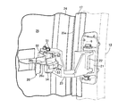
図2および図5から明らかなように、下部ガイドレール20は上面が開放した第1溝部20bと側面が開放した第2溝部20cとを上下2段に備えており、ドアフレーム24から延びる下部アーム28の先端にボールジョイント45を介してスライダ46が揺動自在に支持される。スライダ46に上下方向に延びる2本のピン47,47を介して回転自在に支持された2個の第1下部ガイドローラ48,48が前記第1溝部20bに嵌合するとともに、スライダ46に水平方向に延びるピン49を介して回転自在に支持された第2下部ガイドローラ50が前記第2溝部20cに嵌合する。
As is clear from FIGS. 2 and 5, the
図2および図6から明らかなように、スライドドア15側に設けられた中間ガイドレール26は、上面が開放した第1溝部26bと下面が開放した第2溝部26cとを上下2段に備える。ノーズ側のリングフレーム13に固定したブラケット21に上下方向に延びるピン22を介して基端が枢支された中間アーム23は、その先端に上下方向に延びる2本のピン51,51を介して回転自在に支持された2個の第1中間ガイドローラ52,52と、水平方向に延びる1本のピン53を介して回転自在に支持された1個の第2中間ガイドローラ54とを備えており、2個の第1中間ガイドローラ52,52が中間ガイドレール26の第1溝部26bに嵌合し、1個の第2中間ガイドローラ54が中間ガイドレール26の第2溝部26cに嵌合する。
As is clear from FIGS. 2 and 6, the
次に、上記構成を備えた本発明の実施の形態の作用を説明する。 Next, the operation of the embodiment of the present invention having the above configuration will be described.
スライドドア15は機外から開閉操作される。スライドドア15を開くには、図1において、作業者がスライドドア15のドアスキン25の凹部25bに収納したレバー30を引き起し、上向き(矢印A方向)に操作する。その結果、図2において、支軸31まわりに駆動アーム32が矢印B方向に揺動し、上下の第1リンク38,38が矢印C方向に牽引される。すると従動アーム36,36がピン35,35まわりに矢印D方向に揺動し、2本の第2リンク40,40が矢印E方向に牽引され、それらの先端がドア開口フレーム17のブラケット18,18のピン孔18a,18aから引き抜かれるとともに、2本の第3リンク43,43が矢印F方向に牽引され、それらの先端がドア開口フレーム17のブラケット18,18のピン孔18a,18aから引き抜かれることで、ドア開口フレーム17に対するスライドドア15のロックが解除される。
The sliding
尚、ドア開口フレーム17に対してスライドドア15をロックする場合には、レバー30を逆方向(矢印Aと反対方向)に操作し、2本の第2リンク40,40および2本の第3リンク42,42の先端をドア開口フレーム17のブラケット18…のピン孔18a…に係合させれば良い。
When the sliding
上述のようにしてスライドドア15のロックを解除した後、作業者がレバー30を握ってノーズ側に引くと、図8〜図10に示すように、スライドドア15側の上部アーム27の先端の上部ガイドローラ44が上部ガイドレール19の溝部19bに案内され、下部アーム28の先端の2個の第1下部ガイドローラ48,48が下部ガイドレール20の第1溝部20bに案内されるとともに、1個の第2下部ガイドローラ50が下部ガイドレール20の第2溝部20cに案内され、更にドア開口フレーム17側の中間アーム23の先端の2個の第1中間ガイドローラ52,52が中間ガイドレール26の第1溝部26bに案内されるとともに、1個の第2中間ガイドローラ54が中間ガイドレール26の第2溝部26cに案内されることで、スライドドア15が開放される。
After the unlocking of the
このとき、開放操作の初期段階でスライドドア15側の上部アーム27および下部アーム28は、上部ガイドレール19のテール側端部の湾曲部19aおよび下部ガイドレール20のテール側端部の湾曲部20aに案内され、かつドア開口フレーム17側の中間アーム23は中間ガイドレール26のノーズ側端部の湾曲部26aに案内されることで、スライドドア15はドア開口16から平行移動しながら機外側に迫り出すことができる。従って、その状態からスライドドアがノーズ側にスライドするとき、スライドドア15は胴体11の外面の外表側に沿って移動して胴体11との干渉が回避される。
At this time, at the initial stage of the opening operation, the
スライドドア15がドア開口フレーム17から分離したとき、その重量はスライドドア15側の下部アーム28の第2下部ガイドローラ50が胴体11側の下部ガイドレール20の第2溝部20cに当接し、かつ胴体11側の中間アーム23の第2中間ガイドローラ54がスライドドア15側の中間ガイドレール26の第2溝部26cに当接することで、ドア開口フレーム17側に支持される(図5参照)。その他のガイドローラ44;48,48;52,52は、スライドドア15の移動をガイドする機能を有するもので、スライドドア15の重量を支持する機能はない。
When the
以上のように、スライドドア15の上下方向中間部を案内する中間ガイドレール26を胴体11の外表面ではなくスライドドア15の内面に設けたので、胴体11の外表面に中間ガイドレール26が露出して空気抵抗の増加や信頼性の低下の原因となるのを防止することができる。
As described above, since the
また下部アーム28に、スライドドア15の移動を案内する第1下部ガイドローラ48,48と、スライドドア15の重量を支持する第2下部ガイドローラ50とを設け、下部ガイドレール20に、第1下部ガイドローラ48,48が嵌合する第1溝部20bと第2下部ガイドローラ50が嵌合する第2溝部20cとを上下2段に設けたので、コンパクトな構造でスライドドア15の案内と重量の支持とを両立させることができる。
The
ところで、図1から明らかなように、スライドドア15の近傍の胴体11の断面形状はノーズ側からテール側に向かって次第に細くなるように変化しており、かつドア開口16は胴体11の高さ方向中心から下方に偏倚しているため、ドア開口16の上縁のラインの形状と下縁のラインの形状とは一致しない。従って、ドア開口16の上縁のラインに沿うように上部ガイドレール19の形状を決め、下縁のラインに沿うように下部ガイドレール20の形状を決めると、三次元曲面形状のスライドドア15はスライドの途中で移動不能にロックしてしまい、スムーズに開閉することができなくなる。
As is apparent from FIG. 1, the cross-sectional shape of the fuselage 11 in the vicinity of the
図7にはスライドドア15を上方から見た状態が示されており、ドア開口16の上縁ラインに対してドア開口16の下縁ラインは、非平行でかつ機体内側に偏倚している。特に、ドア開口16の下縁ラインはテール側の端部で機体内側に大きく入り込んでおり、この部分でドア開口16の上縁ラインとの水平方向の距離が大きくなっている。空力上の観点から、上部ガイドレール19および下部ガイドレール20が胴体11のスキンの外側に張り出すことは望ましくないため、上部ガイドレール19をドア開口16の上縁ラインよりも機体内側に配置し、かつ下部ガイドレール20をドア開口16の下縁ラインよりも機体内側に配置する必要がある。
FIG. 7 shows a state in which the
スライドドア15を引っ掛かることなくスムーズにスライドさせるには、上部ガイドレール19および下部ガイドレール20を同一形状にして相互に平行移動した位置に配置すれば良い。しかしながら、上述したように、ドア開口16の下縁ラインはテール側の端部で機体内側に大きく入り込んでいるため、ドア開口16の上縁ラインに設けた上部ガイドレール19をそのまま下方に平行移動して下部ガイドレール20としても、その下部ガイドレール20のテール側の端部が胴体11のスキンの外側に張り出して空気抵抗の増加および信頼性の低下の原因となってしまう問題がある。これを避けるために、上部ガイドレール19および下部ガイドレール20をドア開口16から充分に機体内側に配置すれば良いが、そのようにすると、胴体11内部の空間を圧迫する問題が発生してしまう。
In order to smoothly slide the sliding
そこで本実施の形態では、上記問題を以下のようにして解決している。 Therefore, in the present embodiment, the above problem is solved as follows.
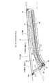
図11は上部ガイドレール19(主ガイドレール)および下部ガイドレール20(副ガイドレール)を上方から見た模式図であって、先ず軸線Luを有する上部ガイドレール19を同一形状(合同形状)のまま下方かつ機体内側方向に平行移動した軸線Liを有する仮想ガイドレール19′を設定する。上部ガイドレール19および仮想ガイドレール19′は同一形状のものを平行移動しただけであるから、対応する各点を結ぶベクトルaは全て同一である。
FIG. 11 is a schematic view of the upper guide rail 19 (main guide rail) and the lower guide rail 20 (sub guide rail) as viewed from above. First, the
軸線Ldを有する下部ガイドレール20上を移動する2個の●は第1下部ガイドローラ48,48(図5参照)を示しており、仮想ガイドレール19′上を移動する1個の○はボールジョイント45(図5参照)を示している。2個の第1下部ガイドローラ48,48およびボールジョイント45はスライダ46(図5参照)によって二等辺三角形の頂点に拘束されているため、ボールジョイント45から2個の第1下部ガイドローラ48,48の中間部を結ぶベクトルbは、大きさは同じであるが方向が異なっている。従って、仮想ガイドレール19′に対して下部ガイドレール20は合同でない別形状となり、下部ガイドレール20の湾曲部20aは上部ガイドレール19の湾曲部19aに比べて強く湾曲するため、下部ガイドレール20を胴体11のスキンに近い位置に配置しても、下部ガイドレール20が胴体11のスキンの外部に露出することが防止される。
Two circles moving on the
尚、スライダ46と下部アーム28とはボールジョイント45で接続されているが、ボールジョイント45を用いた理由は各部の寸法誤差や組立誤差を吸収するためであり、寸法誤差や組立誤差が小さい場合には、上下方向の軸線を有するピンジョイントで接続しても良い。
The
このように、上部ガイドレール19と下部ガイドレール20とを異なる形状にしながら、スライドドア15を引っ掛かることなくスムーズに開閉することが可能になる。しかも下部ガイドレール20の形状の設計自由度を高めることができるので、下部ガイドレール20が胴体11の下部のテール側の絞り込まれた部分と干渉するのを防止し、胴体11のスキンに突起物が形成されるのを回避することができる。
As described above, the
以上のようにして、上部ガイドレール19および下部ガイドレール20の形状が決定されると、スライドドア15の移動軌跡も一義的に決まるため、そのスライドドア15の内面に固定される中間ガイドレール26の形状を、ドア開口16側に設けた第1、第2中間ガイドローラ52,52;54がスムーズに転動できるように決定すれば良い。
As described above, when the shapes of the
以上、本発明の実施の形態を説明したが、本発明は上記実施の形態に限定されるものではなく、特許請求の範囲に記載された本発明を逸脱することなく種々の設計変更を行うことが可能である。 Although the embodiments of the present invention have been described above, the present invention is not limited to the above-described embodiments, and various design changes can be made without departing from the present invention described in the claims. Is possible.
例えば、実施の形態では、上部ガイドレール19を主ガイドレールとして下部ガイドレール20を副ガイドレールとしているが、その関係を逆にしても良い。
For example, in the embodiment, the
また本発明の航空機は飛行機に限定されず、ヘリコプタや飛行船に対しても適用することができる。 Moreover, the aircraft of the present invention is not limited to airplanes, and can be applied to helicopters and airships.
またスライドドア15のスライドを案内するローラに代えて、低摩擦係数のスライダを使用することができる。
Further, a slider having a low friction coefficient can be used in place of the roller for guiding the slide of the
11 胴体
15 スライドドア
16 ドア開口
19 上部ガイドレール(主ガイドレール)
19′ 仮想ガイドレール
20 下部ガイドレール(副ガイドレール、ガイドレール)
20b 第1溝部
20c 第2溝部
23 中間アーム
26 中間ガイドレール
27 上部アーム
28 下部アーム
44 上部ガイドローラ
45 ボールジョイント(支軸部)
46 スライダ
47 ピン(上下軸)
48 第1下部ガイドローラ(第1ガイドローラ、下部ガイドローラ、ガイドローラ)
49 ピン(水平軸)
50 第2下部ガイドローラ(第2ガイドローラ、下部ガイドローラ、ガイドローラ)
52 第1中間ガイドローラ(中間ガイドローラ)
54 第2中間ガイドローラ(中間ガイドローラ)
11
19 '
20b
46
48 First lower guide roller (first guide roller, lower guide roller, guide roller)
49 pins (horizontal axis)
50 Second lower guide roller (second guide roller, lower guide roller, guide roller)
52 First intermediate guide roller (intermediate guide roller)
54 Second intermediate guide roller (intermediate guide roller)
Claims (3)
前記ドア開口(16)の上縁および下縁に沿ってそれぞれ固定した上部ガイドレール(19)および下部ガイドレール(20)に、スライドドア(15)の上部に設けた上部アーム(27)の先端の上部ガイドローラ(44)と、スライドドア(15)の下部に設けた下部アーム(28)の先端の下部ガイドローラ(48,50)とをそれぞれ転動可能に係合させるとともに、前記スライドドア(15)の内面に固定した中間ガイドレール(26)に、前記ドア開口(16)に設けた中間アーム(23)の先端に設けた中間ガイドローラ(52,54)を転動可能に係合させることを特徴とする航空機のスライドドア装置。 In a sliding door device for opening and closing a door opening (16) formed in an aircraft fuselage (11),
The tip of the upper arm (27) provided on the upper part of the sliding door (15) on the upper guide rail (19) and the lower guide rail (20) fixed along the upper and lower edges of the door opening (16), respectively. The upper guide roller (44) and the lower guide roller (48, 50) at the tip of the lower arm (28) provided at the lower part of the slide door (15) are engaged with each other in a rollable manner. An intermediate guide roller (52, 54) provided at the tip of an intermediate arm (23) provided in the door opening (16) is slidably engaged with an intermediate guide rail (26) fixed to the inner surface of (15). A sliding door device for an aircraft, characterized in that
前記副ガイドレール(20)に対応するアーム(28)の先端に支軸部(45)を介してスライダ(46)を枢支し、前記スライダ(46)に設けた複数のガイドローラ(48,50)を前記副ガイドレール(20)に転動可能に係合させ、
前記副ガイドレール(20)の形状は、前記スライダ(46)に設けた複数のガイドローラ(48,50)を前記副ガイドレール(20)に沿って転動させたときに、前記スライダ(46)の支軸部(45)の移動軌跡が前記仮想ガイドレール(19′)に一致するように定められることを特徴とする、請求項1に記載の航空機のスライドドア装置。 One of the upper guide rail and the lower guide rail is a main guide rail (19), the other is a sub guide rail (20), and a virtual guide rail obtained by translating the main guide rail (19) in the vertical direction is hypothesized. It is defined as a guide rail (19 ')
A slider (46) is pivotally supported on the tip of an arm (28) corresponding to the sub guide rail (20) via a support shaft (45), and a plurality of guide rollers (48, 48) provided on the slider (46) are provided. 50) engaging the sub-guide rail (20) in a rollable manner,
The shape of the sub-guide rail (20) is such that when the plurality of guide rollers (48, 50) provided on the slider (46) roll along the sub-guide rail (20), the slider (46 2. The sliding door device for an aircraft according to claim 1, wherein a movement locus of the support shaft portion (45) is determined so as to coincide with the virtual guide rail (19 ′).
Priority Applications (2)
| Application Number | Priority Date | Filing Date | Title |
|---|---|---|---|
| JP2008199836A JP5135110B2 (en) | 2008-08-01 | 2008-08-01 | Aircraft sliding door equipment |
| US12/533,822 US8070102B2 (en) | 2008-08-01 | 2009-07-31 | Slide door device for aircraft |
Applications Claiming Priority (1)
| Application Number | Priority Date | Filing Date | Title |
|---|---|---|---|
| JP2008199836A JP5135110B2 (en) | 2008-08-01 | 2008-08-01 | Aircraft sliding door equipment |
Publications (2)
| Publication Number | Publication Date |
|---|---|
| JP2010036654A true JP2010036654A (en) | 2010-02-18 |
| JP5135110B2 JP5135110B2 (en) | 2013-01-30 |
Family
ID=41798376
Family Applications (1)
| Application Number | Title | Priority Date | Filing Date |
|---|---|---|---|
| JP2008199836A Active JP5135110B2 (en) | 2008-08-01 | 2008-08-01 | Aircraft sliding door equipment |
Country Status (2)
| Country | Link |
|---|---|
| US (1) | US8070102B2 (en) |
| JP (1) | JP5135110B2 (en) |
Cited By (4)
| Publication number | Priority date | Publication date | Assignee | Title |
|---|---|---|---|---|
| JP2016070051A (en) * | 2014-09-23 | 2016-05-09 | エアバス ヘリコプターズ ドイチェランド ゲーエムベーハー | Actuator system for actuatable door and aircraft having such actuatable door |
| CN109606618A (en) * | 2018-12-14 | 2019-04-12 | 中航沈飞民用飞机有限责任公司 | A kind of hatch door timesharing driving mechanism and its application |
| WO2022153909A1 (en) * | 2021-01-12 | 2022-07-21 | Ntn株式会社 | Hub unit with steering function, steering system, and vehicle provided with same |
| JP7379266B2 (en) | 2020-04-22 | 2023-11-14 | 那須電機鉄工株式会社 | Automatic opening/closing shutter structure for hydrogen storage alloy tank storage equipment |
Families Citing this family (28)
| Publication number | Priority date | Publication date | Assignee | Title |
|---|---|---|---|---|
| PL2179919T3 (en) * | 2008-10-21 | 2011-07-29 | Agusta Spa | Aircraft with loading access opening |
| US8109551B2 (en) * | 2009-02-04 | 2012-02-07 | New Flyer Industries Canada Ulc | Bus cabin structure |
| ES2389793B1 (en) * | 2009-12-28 | 2013-10-09 | Eads Construcciones Aeronáuticas S.A. | AIRCRAFT OBSERVATION WINDOW. |
| US8984811B2 (en) | 2010-06-23 | 2015-03-24 | Greenpoint Technologies, Inc. | Door apparatus and method |
| BR112013001443A2 (en) * | 2010-07-19 | 2017-11-14 | Hardoor Top Design & Tech Ltd | sliding door ejection system of a closet |
| US20120267057A1 (en) * | 2011-04-21 | 2012-10-25 | Rydberg James D | Roll-down door arrangements |
| US8794688B2 (en) * | 2012-01-24 | 2014-08-05 | Chrysler Group Llc | Door assembly for a vehicle |
| CN103395490B (en) * | 2013-08-18 | 2015-05-20 | 中航沈飞民用飞机有限责任公司 | Lifting-opening linkage structure for turn-over airliner cabin door |
| EP3061685B1 (en) * | 2015-02-24 | 2017-01-04 | AIRBUS HELICOPTERS DEUTSCHLAND GmbH | A sliding closing element, in particular a sliding door or a sliding window, for a sliding closing element arrangement of a vehicle, in particular of an aircraft |
| EP3168138B1 (en) * | 2015-11-10 | 2018-06-06 | Airbus Operations GmbH | Aircraft door assembly |
| FR3046133B1 (en) * | 2015-12-23 | 2019-06-07 | Airbus Operations | AIRCRAFT CELL COMPRISING A DOOR OPENING IN RECTILINE DIRECTION |
| US10533603B2 (en) * | 2017-03-02 | 2020-01-14 | Bell Helicopter Textron Inc. | Roller track assembly for a tiltrotor proprotor door |
| US10539180B2 (en) | 2017-03-02 | 2020-01-21 | Bell Helicopter Textron Inc. | Bogie mechanism for a tiltrotor proprotor door |
| US11046446B2 (en) | 2017-03-02 | 2021-06-29 | Bell Helicopter Textron Inc. | Tiltrotor aircraft rotating proprotor assembly |
| US10994853B2 (en) | 2017-03-02 | 2021-05-04 | Bell Helicopter Textron Inc. | Tiltrotor aircraft rotating proprotor assembly |
| CN106882358B (en) * | 2017-04-12 | 2023-07-28 | 江苏美龙航空部件有限公司 | Multifunctional automatic positioning mechanism for cargo compartment door of large civil aircraft |
| US20210142147A1 (en) | 2017-06-27 | 2021-05-13 | Semiconductor Energy Laboratory Co., Ltd. | Portable information terminal and problem solving system |
| US10882598B2 (en) * | 2018-04-12 | 2021-01-05 | Bell Textron Inc. | Pressurized sliding door |
| WO2019209150A1 (en) * | 2018-04-26 | 2019-10-31 | Saab Ab | Door latch securing device for aerial vehicle and method of securing a door structure to a fuselage skin structure of an aerial vehicle |
| US10875627B2 (en) | 2018-05-01 | 2020-12-29 | Bell Helicopter Textron Inc. | Movable cover for a proprotor nacelle |
| DE102018114242B4 (en) * | 2018-06-14 | 2020-04-23 | Airbus Operations Gmbh | Emergency exit system |
| FR3087189B1 (en) * | 2018-10-10 | 2022-07-22 | Latecoere | METHOD FOR OPENING/CLOSING AN AIRCRAFT DOOR AND AIRCRAFT FOR IMPLEMENTING SUCH A METHOD |
| US11002054B2 (en) * | 2018-11-09 | 2021-05-11 | GM Global Technology Operations LLC | Sliding door mechanism |
| US11597492B2 (en) * | 2019-01-03 | 2023-03-07 | Textron Innovations Inc. | Sliding door |
| KR102644310B1 (en) * | 2019-01-24 | 2024-03-07 | 현대자동차주식회사 | The weather strip structure of vehicle doors |
| EP3941823A4 (en) * | 2019-03-20 | 2023-03-22 | Scandinavian Cargoloading Technologies AB | Cargo door operating method and device |
| EP3792174B1 (en) * | 2019-09-11 | 2023-01-04 | Rohr Inc. | Door mechanism |
| GB2589311A (en) * | 2019-11-07 | 2021-06-02 | Morris Commercial Ltd | Sliding door assembly in a motor vehicle |
Citations (8)
| Publication number | Priority date | Publication date | Assignee | Title |
|---|---|---|---|---|
| JPS6267899A (en) * | 1985-09-20 | 1987-03-27 | ダイニツク株式会社 | Part for electromagnetic wave shield |
| JPH0355320A (en) * | 1989-07-25 | 1991-03-11 | Kensetsu Kiso Eng Kk | Construction of slope-protecting structure |
| JPH04353129A (en) * | 1991-05-30 | 1992-12-08 | Komatsu Ltd | Driver's cab for construction equipment |
| JPH1037581A (en) * | 1996-07-23 | 1998-02-10 | Daihatsu Motor Co Ltd | Vehicular slide door device |
| JP2000198356A (en) * | 1998-12-29 | 2000-07-18 | Komatsu Ltd | Slide door for vehicle |
| JP2003211965A (en) * | 2002-01-24 | 2003-07-30 | Mitsubishi Automob Eng Co Ltd | Arm device of slide door for vehicle |
| JP2004332229A (en) * | 2003-04-30 | 2004-11-25 | Mitsubishi Agricult Mach Co Ltd | Door structure of cabin |
| JP2005178770A (en) * | 2003-12-22 | 2005-07-07 | Airbus Deutschland Gmbh | Aircraft door |
Family Cites Families (7)
| Publication number | Priority date | Publication date | Assignee | Title |
|---|---|---|---|---|
| US2378856A (en) * | 1941-02-06 | 1945-06-19 | Cons Vultee Aircraft Corp | Sliding closure for aircraft |
| US3131892A (en) * | 1962-06-11 | 1964-05-05 | Eltra Corp | Door latch assembly |
| US3728819A (en) * | 1970-04-28 | 1973-04-24 | Kiekert Soehne Arn | Vehicle doors |
| GB1559695A (en) * | 1976-11-26 | 1980-01-23 | Vauxhall Motors Ltd | Motor vehicle having a sliding door |
| US5832668A (en) * | 1997-06-02 | 1998-11-10 | Chrysler Corporation | Vehicle sliding door modular glide system |
| US6189833B1 (en) * | 1998-09-29 | 2001-02-20 | Sikorsky Aircraft Corporation | Aircraft sliding door system |
| US6328374B1 (en) * | 2000-06-21 | 2001-12-11 | Ford Global Technologies, Inc. | Fully-openable slidable vehicle door assembly |
-
2008
- 2008-08-01 JP JP2008199836A patent/JP5135110B2/en active Active
-
2009
- 2009-07-31 US US12/533,822 patent/US8070102B2/en active Active
Patent Citations (8)
| Publication number | Priority date | Publication date | Assignee | Title |
|---|---|---|---|---|
| JPS6267899A (en) * | 1985-09-20 | 1987-03-27 | ダイニツク株式会社 | Part for electromagnetic wave shield |
| JPH0355320A (en) * | 1989-07-25 | 1991-03-11 | Kensetsu Kiso Eng Kk | Construction of slope-protecting structure |
| JPH04353129A (en) * | 1991-05-30 | 1992-12-08 | Komatsu Ltd | Driver's cab for construction equipment |
| JPH1037581A (en) * | 1996-07-23 | 1998-02-10 | Daihatsu Motor Co Ltd | Vehicular slide door device |
| JP2000198356A (en) * | 1998-12-29 | 2000-07-18 | Komatsu Ltd | Slide door for vehicle |
| JP2003211965A (en) * | 2002-01-24 | 2003-07-30 | Mitsubishi Automob Eng Co Ltd | Arm device of slide door for vehicle |
| JP2004332229A (en) * | 2003-04-30 | 2004-11-25 | Mitsubishi Agricult Mach Co Ltd | Door structure of cabin |
| JP2005178770A (en) * | 2003-12-22 | 2005-07-07 | Airbus Deutschland Gmbh | Aircraft door |
Cited By (4)
| Publication number | Priority date | Publication date | Assignee | Title |
|---|---|---|---|---|
| JP2016070051A (en) * | 2014-09-23 | 2016-05-09 | エアバス ヘリコプターズ ドイチェランド ゲーエムベーハー | Actuator system for actuatable door and aircraft having such actuatable door |
| CN109606618A (en) * | 2018-12-14 | 2019-04-12 | 中航沈飞民用飞机有限责任公司 | A kind of hatch door timesharing driving mechanism and its application |
| JP7379266B2 (en) | 2020-04-22 | 2023-11-14 | 那須電機鉄工株式会社 | Automatic opening/closing shutter structure for hydrogen storage alloy tank storage equipment |
| WO2022153909A1 (en) * | 2021-01-12 | 2022-07-21 | Ntn株式会社 | Hub unit with steering function, steering system, and vehicle provided with same |
Also Published As
| Publication number | Publication date |
|---|---|
| US8070102B2 (en) | 2011-12-06 |
| US20100059628A1 (en) | 2010-03-11 |
| JP5135110B2 (en) | 2013-01-30 |
Similar Documents
| Publication | Publication Date | Title |
|---|---|---|
| JP5135110B2 (en) | Aircraft sliding door equipment | |
| CN102481828B (en) | Vehicle door structure | |
| US6834834B2 (en) | Articulation device for an aircraft door panel and an aircraft door integrating such a device | |
| CN205440035U (en) | Be used for locking orbital device of vehicle seat | |
| JP6144129B2 (en) | Sliding door | |
| US8336949B2 (en) | Link-type sliding door mechanism | |
| JP6251278B2 (en) | Aircraft door mechanism with handle actuated lowerer | |
| JP5517149B2 (en) | aircraft | |
| CN103132874A (en) | Closure assembly with moveable cover and closeout for a retractable handle | |
| CN102555745A (en) | Multi link retracting seal surface module | |
| CN107031819A (en) | Folding wing for aircraft and the aircraft with folding wing | |
| US10259299B2 (en) | Sliding door structure | |
| JP2014061766A (en) | Door structure for vehicle | |
| KR20210069304A (en) | Structure for preventing movement of opposed type sliding doors | |
| US11787271B2 (en) | Sliding door device for vehicle | |
| CN101258043B (en) | Vehicle roof with at least two cover elements | |
| CN107512158B (en) | Reinforcing formula automobile side angle door structure | |
| JPH0460864B2 (en) | ||
| EP3159218A2 (en) | Pinch-protection sliding trim cover assembly for a vehicle sliding door | |
| JP6306310B2 (en) | Drive mechanism and open roof structure including the drive mechanism | |
| JP5860691B2 (en) | Home door device | |
| CN210554102U (en) | Sliding vehicle door and vehicle | |
| JP4291224B2 (en) | Plug door device for vehicle | |
| JP2015105054A (en) | Door device for railway vehicle | |
| CN212450222U (en) | Elevator car door storage structure |
Legal Events
| Date | Code | Title | Description |
|---|---|---|---|
| A621 | Written request for application examination |
Free format text: JAPANESE INTERMEDIATE CODE: A621 Effective date: 20101126 |
|
| A977 | Report on retrieval |
Free format text: JAPANESE INTERMEDIATE CODE: A971007 Effective date: 20120202 |
|
| A131 | Notification of reasons for refusal |
Free format text: JAPANESE INTERMEDIATE CODE: A131 Effective date: 20120209 |
|
| A521 | Request for written amendment filed |
Free format text: JAPANESE INTERMEDIATE CODE: A523 Effective date: 20120402 |
|
| A711 | Notification of change in applicant |
Free format text: JAPANESE INTERMEDIATE CODE: A711 Effective date: 20120925 |
|
| TRDD | Decision of grant or rejection written | ||
| A521 | Request for written amendment filed |
Free format text: JAPANESE INTERMEDIATE CODE: A821 Effective date: 20120925 |
|
| A01 | Written decision to grant a patent or to grant a registration (utility model) |
Free format text: JAPANESE INTERMEDIATE CODE: A01 Effective date: 20121031 |
|
| A01 | Written decision to grant a patent or to grant a registration (utility model) |
Free format text: JAPANESE INTERMEDIATE CODE: A01 |
|
| A61 | First payment of annual fees (during grant procedure) |
Free format text: JAPANESE INTERMEDIATE CODE: A61 Effective date: 20121112 |
|
| FPAY | Renewal fee payment (event date is renewal date of database) |
Free format text: PAYMENT UNTIL: 20151116 Year of fee payment: 3 |
|
| R150 | Certificate of patent or registration of utility model |
Free format text: JAPANESE INTERMEDIATE CODE: R150 Ref document number: 5135110 Country of ref document: JP Free format text: JAPANESE INTERMEDIATE CODE: R150 |
|
| R250 | Receipt of annual fees |
Free format text: JAPANESE INTERMEDIATE CODE: R250 |
|
| R250 | Receipt of annual fees |
Free format text: JAPANESE INTERMEDIATE CODE: R250 |
|
| R250 | Receipt of annual fees |
Free format text: JAPANESE INTERMEDIATE CODE: R250 |
|
| R250 | Receipt of annual fees |
Free format text: JAPANESE INTERMEDIATE CODE: R250 |
|
| R250 | Receipt of annual fees |
Free format text: JAPANESE INTERMEDIATE CODE: R250 |
|
| R250 | Receipt of annual fees |
Free format text: JAPANESE INTERMEDIATE CODE: R250 |
|
| R250 | Receipt of annual fees |
Free format text: JAPANESE INTERMEDIATE CODE: R250 |
|
| R250 | Receipt of annual fees |
Free format text: JAPANESE INTERMEDIATE CODE: R250 |
|
| R250 | Receipt of annual fees |
Free format text: JAPANESE INTERMEDIATE CODE: R250 |