JP2010036147A - System for removing water-soluble organic compound - Google Patents
System for removing water-soluble organic compound Download PDFInfo
- Publication number
- JP2010036147A JP2010036147A JP2008204058A JP2008204058A JP2010036147A JP 2010036147 A JP2010036147 A JP 2010036147A JP 2008204058 A JP2008204058 A JP 2008204058A JP 2008204058 A JP2008204058 A JP 2008204058A JP 2010036147 A JP2010036147 A JP 2010036147A
- Authority
- JP
- Japan
- Prior art keywords
- water
- organic compound
- soluble organic
- scrubber
- reaction tank
- Prior art date
- Legal status (The legal status is an assumption and is not a legal conclusion. Google has not performed a legal analysis and makes no representation as to the accuracy of the status listed.)
- Granted
Links
- 150000002894 organic compounds Chemical class 0.000 title claims abstract description 53
- XLYOFNOQVPJJNP-UHFFFAOYSA-N water Substances O XLYOFNOQVPJJNP-UHFFFAOYSA-N 0.000 claims abstract description 92
- 238000006243 chemical reaction Methods 0.000 claims abstract description 49
- CBENFWSGALASAD-UHFFFAOYSA-N Ozone Chemical compound [O-][O+]=O CBENFWSGALASAD-UHFFFAOYSA-N 0.000 claims abstract description 27
- 239000011941 photocatalyst Substances 0.000 claims abstract description 27
- 239000000945 filler Substances 0.000 claims abstract description 25
- 239000007791 liquid phase Substances 0.000 claims abstract description 24
- 238000000354 decomposition reaction Methods 0.000 claims description 21
- 239000000835 fiber Substances 0.000 claims description 7
- 229910010413 TiO 2 Inorganic materials 0.000 claims description 6
- 239000004745 nonwoven fabric Substances 0.000 claims description 5
- 239000007789 gas Substances 0.000 description 31
- OKTJSMMVPCPJKN-UHFFFAOYSA-N Carbon Chemical compound [C] OKTJSMMVPCPJKN-UHFFFAOYSA-N 0.000 description 26
- 239000007788 liquid Substances 0.000 description 14
- 238000000034 method Methods 0.000 description 14
- 239000012855 volatile organic compound Substances 0.000 description 8
- 230000000694 effects Effects 0.000 description 7
- 238000001914 filtration Methods 0.000 description 7
- 238000013032 photocatalytic reaction Methods 0.000 description 6
- 238000010521 absorption reaction Methods 0.000 description 5
- 238000005192 partition Methods 0.000 description 5
- 239000000126 substance Substances 0.000 description 5
- 239000003595 mist Substances 0.000 description 4
- 238000006864 oxidative decomposition reaction Methods 0.000 description 4
- 230000002195 synergetic effect Effects 0.000 description 4
- YXFVVABEGXRONW-UHFFFAOYSA-N Toluene Chemical compound CC1=CC=CC=C1 YXFVVABEGXRONW-UHFFFAOYSA-N 0.000 description 3
- 230000009471 action Effects 0.000 description 3
- 230000002411 adverse Effects 0.000 description 3
- 238000009841 combustion method Methods 0.000 description 3
- -1 hydroxy radicals Chemical class 0.000 description 3
- 230000004048 modification Effects 0.000 description 3
- 238000012986 modification Methods 0.000 description 3
- NJPPVKZQTLUDBO-UHFFFAOYSA-N novaluron Chemical compound C1=C(Cl)C(OC(F)(F)C(OC(F)(F)F)F)=CC=C1NC(=O)NC(=O)C1=C(F)C=CC=C1F NJPPVKZQTLUDBO-UHFFFAOYSA-N 0.000 description 3
- 238000001179 sorption measurement Methods 0.000 description 3
- 238000006065 biodegradation reaction Methods 0.000 description 2
- 230000015556 catabolic process Effects 0.000 description 2
- 238000006731 degradation reaction Methods 0.000 description 2
- 239000002245 particle Substances 0.000 description 2
- 239000000791 photochemical oxidant Substances 0.000 description 2
- 230000008569 process Effects 0.000 description 2
- 238000007348 radical reaction Methods 0.000 description 2
- 150000003254 radicals Chemical class 0.000 description 2
- 210000002345 respiratory system Anatomy 0.000 description 2
- 239000002250 absorbent Substances 0.000 description 1
- 230000002745 absorbent Effects 0.000 description 1
- 230000008901 benefit Effects 0.000 description 1
- 238000007084 catalytic combustion reaction Methods 0.000 description 1
- 238000003795 desorption Methods 0.000 description 1
- 150000002013 dioxins Chemical class 0.000 description 1
- 238000001035 drying Methods 0.000 description 1
- 230000007613 environmental effect Effects 0.000 description 1
- 230000008821 health effect Effects 0.000 description 1
- 230000002209 hydrophobic effect Effects 0.000 description 1
- 239000002440 industrial waste Substances 0.000 description 1
- 230000001678 irradiating effect Effects 0.000 description 1
- 230000007794 irritation Effects 0.000 description 1
- 238000012423 maintenance Methods 0.000 description 1
- 238000004519 manufacturing process Methods 0.000 description 1
- 239000002105 nanoparticle Substances 0.000 description 1
- 238000007254 oxidation reaction Methods 0.000 description 1
- 238000012856 packing Methods 0.000 description 1
- 239000003973 paint Substances 0.000 description 1
- 238000010422 painting Methods 0.000 description 1
- 239000013618 particulate matter Substances 0.000 description 1
- 229920000098 polyolefin Polymers 0.000 description 1
- 238000012545 processing Methods 0.000 description 1
- 238000011084 recovery Methods 0.000 description 1
- 238000006722 reduction reaction Methods 0.000 description 1
- 230000008929 regeneration Effects 0.000 description 1
- 238000011069 regeneration method Methods 0.000 description 1
- 239000004065 semiconductor Substances 0.000 description 1
- 238000010008 shearing Methods 0.000 description 1
- 239000002904 solvent Substances 0.000 description 1
- 229920003002 synthetic resin Polymers 0.000 description 1
- 239000000057 synthetic resin Substances 0.000 description 1
- 230000002463 transducing effect Effects 0.000 description 1
- 230000008016 vaporization Effects 0.000 description 1
- 239000002912 waste gas Substances 0.000 description 1
- 239000002699 waste material Substances 0.000 description 1
Images


Landscapes
- Exhaust Gas Treatment By Means Of Catalyst (AREA)
- Catalysts (AREA)
- Treating Waste Gases (AREA)
- Physical Water Treatments (AREA)
- Treatment Of Water By Oxidation Or Reduction (AREA)
Abstract
Description
本発明は、工場等からの排出ガスに含まれる水溶性有機化合物の除去システムに係り、特に、微細気泡と液相系光触媒を用いることにより、水溶性有機化合物の除去効率を大幅に向上させた水溶性有機化合物の除去システムに関するものである。 The present invention relates to a system for removing water-soluble organic compounds contained in exhaust gas from factories and the like, and in particular, by using fine bubbles and a liquid-phase photocatalyst, the removal efficiency of water-soluble organic compounds has been greatly improved. The present invention relates to a water-soluble organic compound removal system.
浮遊粒子状物質(以下、SPM;Suspended Particulate Matter)による人の呼吸器への悪影響、光化学オキシダントによる目やのどへの刺激や呼吸器への悪影響などの健康被害は未だに生じており、これら大気汚染物質への対処が求められている。このSPM及び光化学オキシダントの発生原因は多岐に渡っているが、揮発性有機化合物(以下、VOC;Volatile Organic Compounds)がその原因の1つとなっており、VOC排出源である印刷工場、塗装工場、半導体製造工場等では、VOCの除去が求められている。 Suspended Particulate Matter (hereinafter referred to as “SPM”) is causing adverse health effects such as adverse effects on human respiratory tract, irritation to eyes and throat and adverse effects on respiratory tract due to photochemical oxidants. There is a need to deal with substances. There are various causes for the occurrence of SPM and photochemical oxidants, but volatile organic compounds (hereinafter referred to as VOC) are one of the causes, and printing factories, painting factories, In semiconductor manufacturing factories and the like, removal of VOC is required.
水溶性の揮発性有機化合物(以下、WSOC;Water Soluble Organic Compounds)はVOCの一部であり、トルエンなど不溶性VOCの代替として、塗装工場で使用されるようになってきているほか、製品の乾燥工場ではIPAが使用されるなど、工場からの排出ガスにWSOCが含まれる場合は多い。 Water-soluble volatile organic compounds (hereinafter referred to as WSOC) are part of VOCs and are increasingly used in paint shops as an alternative to insoluble VOCs such as toluene, as well as product drying. There are many cases where WSOC is contained in the exhaust gas from the factory, such as when IPA is used in the factory.
一般に、VOCを分解除去する方法としては、(a)直接燃焼法、(b)蓄熱燃焼法、(c)触媒燃焼法、(d)生物分解法、(e)活性炭吸着法、(f)低温プラズマ分解法などがある(特許文献1、特許文献2等)。
しかしながら、VOCを分解除去する方法として用いられている上記(a)〜(c)の各種燃焼法においては、大規模な事業所の場合、CO2の排出量が多くなるという問題点があり、また、分解生成物がダイオキシン等の有害物質を発生させる危険性があるという問題点があった。 However, in the various combustion methods (a) to (c) used as a method for decomposing and removing VOC, there is a problem that CO 2 emissions increase in a large-scale establishment. In addition, there is a problem that the decomposition product has a risk of generating harmful substances such as dioxins.
また、(d)生物分解法においては、分解速度が遅い上、入口濃度が変動すると分解効率が不安定になりやすいという問題点があり、(e)活性炭吸着法においては、活性炭が破過した場合、活性炭を産業廃棄物にして処理しなければならないという問題点があった。また、再生を行う場合は、熱などのエネルギーを投入しなければならず、脱着した場合は溶剤の回収装置が必要となるという問題点があった。さらに、(f)低温プラズマ分解法においては、大量処理ができないといった問題点が挙げられる等、既存の方法は様々な問題を抱えていた。 In addition, (d) in the biodegradation method, there is a problem that the degradation rate is slow and the degradation efficiency tends to become unstable when the inlet concentration varies. (E) In the activated carbon adsorption method, the activated carbon broke through. In this case, there was a problem that the activated carbon had to be treated as industrial waste. In addition, when regeneration is performed, energy such as heat must be input, and in the case of desorption, a solvent recovery device is required. Furthermore, (f) the low temperature plasma decomposition method has various problems such as a problem that a large amount of processing cannot be performed.
一方、WSOC除去には、上記の方法のほか、(g)吸収法の適用が可能であるが、薬液の維持管理や廃液処理が必要なため、ランニングコストが高くなるほか、吸収液として水を使用した場合は、除去性能及び補給水量の増加などの問題があった。 On the other hand, in addition to the above method, (g) the absorption method can be applied to remove WSOC. However, maintenance and management of the chemical solution and waste liquid treatment are required, which increases the running cost and uses water as the absorption solution. When used, there were problems such as an increase in removal performance and the amount of makeup water.
本発明は、上述したような従来技術の問題点を解決するために提案されたものであり、その目的は、簡便なシステム構成で、排ガス中に含まれる水溶性有機化合物を効率良く分解除去することができる水溶性有機化合物の除去システムを提供することにある。 The present invention has been proposed in order to solve the above-described problems of the prior art, and its purpose is to efficiently decompose and remove water-soluble organic compounds contained in exhaust gas with a simple system configuration. It is an object of the present invention to provide a removal system for water-soluble organic compounds.
上記目的を達成するため、請求項1に記載の水溶性有機化合物の除去システムは、容器内に所定の充填材が設置され、該充填材の上部から水が滴下されるように構成されたスクラバーと、容器内に液相系光触媒及び紫外線ランプが設置されると共に、微細気泡を発生させる微細気泡発生ノズルが設置された反応槽とを備えたことを特徴とするものである。 In order to achieve the above object, the water-soluble organic compound removal system according to claim 1 is a scrubber configured such that a predetermined filler is installed in a container and water is dropped from an upper portion of the filler. And a reaction vessel in which a liquid phase photocatalyst and an ultraviolet lamp are installed in a container, and a fine bubble generating nozzle for generating fine bubbles is provided.
また、請求項2に記載の水溶性有機化合物の除去システムは、容器内に所定の充填材が設置され、該充填材の上部から水が滴下されるように構成されたスクラバーと、容器内に液相系光触媒及び紫外線ランプが設置されると共に、微細気泡を発生させる微細気泡発生ノズルが設置された反応槽とを備え、前記スクラバーに水溶性有機化合物を含む排ガスを導入して、スクラバー内の水に水溶性有機化合物を溶解させた後、この水を前記反応槽に導入し、前記反応槽において、水溶性有機化合物の分解処理を行うように構成したことを特徴とするものである。 Further, the water-soluble organic compound removal system according to claim 2 includes a scrubber configured such that a predetermined filler is installed in the container and water is dropped from the upper part of the filler, A liquid phase photocatalyst and an ultraviolet lamp are installed, and a reaction tank in which a fine bubble generating nozzle for generating fine bubbles is installed, and an exhaust gas containing a water-soluble organic compound is introduced into the scrubber, After the water-soluble organic compound is dissolved in water, the water is introduced into the reaction tank, and the water-soluble organic compound is decomposed in the reaction tank.
上記のような構成を有する請求項1及び請求項2に記載の発明によれば、スクラバー内の水を水溶性有機化合物の吸収液として用いることにより、ランニングコストを削減することができる。また、水溶性有機化合物を溶解した水を、液相系光触媒を設置した反応槽内に導入し、該反応槽内において微細気泡を発生させると共に紫外線を照射することにより、水溶性有機化合物と光触媒との接触効率を大幅に向上させることができ、液相系光触媒反応によって水溶性有機化合物の分解処理を高効率で行うことができる。 According to the first and second aspects of the invention having the above-described configuration, the running cost can be reduced by using the water in the scrubber as the water-soluble organic compound absorbent. In addition, water in which a water-soluble organic compound is dissolved is introduced into a reaction vessel in which a liquid-phase photocatalyst is installed, and microbubbles are generated in the reaction vessel and irradiated with ultraviolet rays. Can be significantly improved, and the water-soluble organic compound can be decomposed with high efficiency by a liquid phase photocatalytic reaction.
請求項3に記載の発明は、請求項1又は請求項2に記載の水溶性有機化合物の除去システムにおいて、前記反応槽において水溶性有機化合物の分解処理がなされた水を、再度前記スクラバーに循環供給するように構成したことを特徴とするものである。 According to a third aspect of the present invention, in the water-soluble organic compound removal system according to the first or second aspect, water in which the water-soluble organic compound has been decomposed in the reaction tank is recycled to the scrubber again. It is characterized by being configured to supply.
上記のような構成を有する請求項3に記載の発明によれば、水溶性有機化合物を溶解した水を反応槽において連続して処理することができると共に、再度、スクラバーに供給して利用することが可能となるので、スクラバーへの補給水を大幅に削減することができる。 According to the invention described in claim 3 having the above-described configuration, water in which the water-soluble organic compound is dissolved can be continuously processed in the reaction tank, and is again supplied to the scrubber for use. As a result, it is possible to greatly reduce the amount of water supplied to the scrubber.
請求項4に記載の発明は、請求項1乃至請求項3のいずれか一に記載の水溶性有機化合物の除去システムにおいて、前記微細気泡が、オゾン含有微細気泡であることを特徴とするものである。 The invention according to claim 4 is the water-soluble organic compound removal system according to any one of claims 1 to 3, wherein the fine bubbles are ozone-containing fine bubbles. is there.
上記のような構成を有する請求項4に記載の発明によれば、オゾン含有微細気泡中のオゾン分子が循環水中に効率良く溶解し、水中のオゾン分子は自己分解によりヒドロキシラジカル(・OH)を生成する。これにより、水中において、ヒドロキシラジカル(・OH)によるフリーラジカル反応が起こるため、効率良くWSOCを分解することができる。その結果、反応槽内において、ヒドロキシラジカル(・OH)による酸化分解と液相系光触媒反応の相乗効果を得ることができるので、WSOCの分解効率を大幅に向上させることができる。 According to the invention of claim 4 having the above-described configuration, the ozone molecules in the ozone-containing fine bubbles are efficiently dissolved in the circulating water, and the ozone molecules in the water decompose hydroxy radicals (.OH) by self-decomposition. Generate. Thereby, since free radical reaction by hydroxy radical (.OH) occurs in water, WSOC can be efficiently decomposed. As a result, a synergistic effect of the oxidative decomposition by hydroxy radical (.OH) and the liquid phase photocatalytic reaction can be obtained in the reaction tank, so that the decomposition efficiency of WSOC can be greatly improved.
請求項5に記載の発明は、請求項1乃至請求項4のいずれか一に記載の水溶性有機化合物の除去システムにおいて、前記液相系光触媒が、粉末状のTiO2光触媒を所定のプラスチック表面又は繊維小片表面に担持したもの、又は、担持媒体として不織布を用いたものであることを特徴とするものである。
The invention according to
上記のような構成を有する請求項5に記載の発明によれば、粉末状のTiO2光触媒を所定のプラスチック表面又は繊維小片表面に担持したものを用い、これを所定の大きさに切断して短冊状にし、処理対象となる溶液内に分散させ、水流により自由に動くことができるように設置する、あるいは、容器の中央部又は底部に層状に固定配置することにより、紫外線ランプから照射されるエネルギーを効率良く受けることができるので、光触媒反応による水溶性有機化合物の分解処理を高効率で行うことができる。また、さらに分解効率を高めるためには、担持媒体として不織布を用いると良い。
According to the invention described in
請求項6に記載の発明は、請求項1乃至請求項5のいずれか一に記載の水溶性有機化合物の除去システムにおいて、前記スクラバーと反応槽とが、上下に積層配置されていることを特徴とするものである。
上記のような構成を有する請求項6に記載の発明によれば、反応槽をスクラバーの下部に設置することにより、大幅な省スペース化を実現することができる。
A sixth aspect of the present invention is the water-soluble organic compound removal system according to any one of the first to fifth aspects, wherein the scrubber and the reaction tank are stacked one above the other. It is what.
According to invention of
請求項7に記載の発明は、請求項1乃至請求項6のいずれか一に記載の水溶性有機化合物の除去システムにおいて、前記充填材が高密度に配置されていることを特徴とするものである。
上記のような構成を有する請求項7に記載の発明によれば、充填材における気液接触面積を大きくすることができるので、水溶性有機化合物の除去効率を向上させることができる。
A seventh aspect of the present invention is the water-soluble organic compound removal system according to any one of the first to sixth aspects, wherein the fillers are arranged at a high density. is there.
According to the invention described in
本発明によれば、簡便なシステム構成で、排ガス中に含まれる水溶性有機化合物を効率良く分解除去することができる水溶性有機化合物の除去システムを提供することができる。 ADVANTAGE OF THE INVENTION According to this invention, the removal system of the water-soluble organic compound which can decompose | disassemble and remove the water-soluble organic compound contained in waste gas efficiently with a simple system structure can be provided.
具体的には、WSOCの吸収液としてスクラバーに供給される水を用いることにより、ランニングコストを削減できるだけでなく、吸収液中に含まれるWSOCをオゾン含有微細気泡及び液相系光触媒によって分解することで、吸収液となる水の連続処理及び再利用が可能となるため、スクラバーへの補給水を大幅に削減することができる。 Specifically, by using water supplied to the scrubber as the WSOC absorption liquid, not only can the running cost be reduced, but also the WSOC contained in the absorption liquid can be decomposed by ozone-containing fine bubbles and a liquid phase photocatalyst. Therefore, since the continuous treatment and reuse of the water that becomes the absorbing liquid is possible, the makeup water to the scrubber can be greatly reduced.
以下、本発明に係る水溶性有機化合物の除去システムの具体的な実施の形態(以下、実施形態という)を、図面を参照して説明する。 Hereinafter, specific embodiments (hereinafter referred to as embodiments) of a water-soluble organic compound removal system according to the present invention will be described with reference to the drawings.
(1)第1実施形態
(1−1)構成
(1−1−1)全体構成
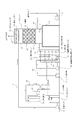
本実施形態の水溶性有機化合物の除去システムは、図1に示すように、WSOCを含む排ガスを水と接触させることにより、排ガス中のWSOC濃度を低減させるスクラバー1と、このスクラバー1に供給される循環水に溶解したWSOCを分解する反応槽2と、この反応槽2における処理後の循環水を貯留し、活性炭による吸着処理を行う下部水槽3と、この下部水槽3の下流側に設けられたクッションタンク4と、循環水を前記スクラバー1に循環供給する循環ポンプ5及び循環用配管7とから構成されている。なお、前記スクラバー1は、台座6の上に設置されている。
(1) First Embodiment (1-1) Configuration (1-1-1) Overall Configuration As shown in FIG. 1, the water-soluble organic compound removal system of this embodiment contacts exhaust gas containing WSOC with water. The scrubber 1 for reducing the WSOC concentration in the exhaust gas, the reaction tank 2 for decomposing WSOC dissolved in the circulating water supplied to the scrubber 1, and the treated circulating water in the reaction tank 2 are stored. A lower water tank 3 that performs adsorption treatment with activated carbon, a cushion tank 4 provided on the downstream side of the lower water tank 3, a
(1−1−2)スクラバーの構成
前記スクラバー1は筒状容器10から構成され、その容器の中央部には所定の充填材11が充填され、この充填材11の上下にはそれぞれ上部空間12及び下部空間13が形成されている。そして、前記下部空間13には、処理対象となるWSOCを含む排ガスを該スクラバー1内に導入する排ガス供給配管14が接続されると共に、排ガス中のWSOCを溶解した循環水15を後述する反応槽2に送るための循環水排出配管16が接続されている。なお、前記排ガス供給配管14には送風機17が設けられ、スクラバー1内に導入する排ガス量を適宜調整できるように構成されている。なお、前記筒状容器10には、円柱状容器だけでなく、角柱状容器も含まれる。
(1-1-2) Configuration of Scrubber The scrubber 1 is composed of a
一方、前記上部空間12には散水ヘッダー18が設けられ、後述する反応槽2等で処理された循環水を前記充填材11に散水するように構成されている。また、散水ヘッダー18の上部にはミストセパレータ19が設けられ、このミストセパレータ19を通過した処理後の排ガスが、筒状容器10の上端に設けられた排ガス排出配管20を介して外部に排出されるように構成されている。
On the other hand, a
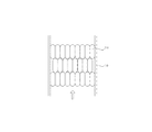
上記のような構成を有するスクラバー1に導入された排ガス中のWSOCは、散水ヘッダー18によって上部から滴下された循環水(水)により充填材11の表面に形成された液膜で吸収除去される。そのため、スクラバー1内に配置される充填材11は、図2に示すように、高密度に組合せ配置することが好ましい。このように配置することにより、気液接触面積を大きくすることができるので、WSOCの除去効率を向上させることができる。
The WSOC in the exhaust gas introduced into the scrubber 1 having the above-described configuration is absorbed and removed by a liquid film formed on the surface of the
また、上記充填材11としては、有効面積が大きく、圧損が小さいこと、合成樹脂製で化学的、機械的性質が強いこと、軽量で充填材取出し作業が容易であること、懸濁物質(SS)などの付着物の除去が容易である充填材が好ましい(例えば、テラレット(商品名):月島環境エンジニアリング社製)。なお、処理対象物質によっては、容易に気液接触面積を向上できる気化式加湿膜(例えば、VHRシリーズ:ウェットマスター社製)を利用しても良い。
In addition, the
(1−1−3)反応槽の構成
前記反応槽2は筒状容器21から構成され、その容器内には所定の液相系光触媒22及び紫外線ランプ23が設置されている。なお、前記液相系光触媒22としては、粉末状TiO2光触媒をプラスチック表面や繊維小片表面に担持したもの、又は、担持媒体として不織布(ポリオレフィンのような疎水性繊維または親水性繊維)を用いたものを、所定の大きさに切って短冊状にしたものを用いることが好ましい。なお、前記筒状容器21には、円柱状容器だけでなく、角柱状容器も含まれる。
(1-1-3) Configuration of Reaction Tank The reaction tank 2 is composed of a
そして、粉末状TiO2光触媒をプラスチック表面や繊維小片表面に担持したもの、又は、粉末状TiO2光触媒を担持した不織布を、反応槽内に分散させ、水流により自由に動くことができるように設置する、あるいは、容器の中央部に層状に固定配置する。なお、上記のように構成した液相系光触媒22を反応槽2内に分散配置した場合には、液相系光触媒22は容器内の水流により移動が可能となるため、紫外線ランプ23から照射されるエネルギーを効率良く受けることができる。
The powdery TiO 2 photocatalyst supported on the plastic surface or the fiber piece surface, or the non-woven fabric carrying the powdered TiO 2 photocatalyst is dispersed in the reaction tank and installed so that it can move freely by the water flow. Alternatively, it is fixedly arranged in a layered manner in the center of the container. When the
また、紫外線ランプ23としては、水中で使用可能な紫外線ランプ(主波長254nm(UV254)、主波長254nm(185nmを数%含む、(UV254+185))を用いることが好ましい。
As the
また、前記反応槽2内には、微細気泡発生ノズル24が設置され、この微細気泡発生ノズル24には、微細気泡発生用ポンプ25が接続されると共に、オゾン供給配管26を介してオゾン発生器27あるいはオゾンガスボンベが接続されている。なお、前記微細気泡発生ノズル24は、高速せん断方式等によりnmサイズ又はμmサイズ、あるいはその両方の気泡径を有する微細気泡を発生させる装置であり、これにより反応槽2内において数十nm〜数十μmの微細気泡を発生させることができるように構成されている。なお、ここでいう微細気泡とは、マイクロサイズの気泡、ナノサイズの気泡、またはその両方を含む気泡であり、微細気泡発生直後の粒径が数十nm〜数十μmの微細な気泡をいう。
Further, a fine
なお、図1に示した本実施形態においては、微細気泡発生ノズル24にはオゾン供給配管26を介してオゾンが導入されるように構成されているが、オゾンの代わりに空気を投入して、微細気泡を発生させるように構成しても良い。
In the present embodiment shown in FIG. 1, ozone is introduced into the fine
(1−1−4)下部水槽及びクッションタンクの構成
図1に示すように、前記反応槽2においてWSOCの分解処理がなされた循環水が導入される下部水槽3には、配管31を介してポンプ32及び活性炭塔33が接続されている。そして、前記反応槽2において一次分解または完全分解まで至らなかったWSOCを活性炭に吸着させることができるように構成されている。
(1-1-4) Configuration of Lower Water Tank and Cushion Tank As shown in FIG. 1, the lower water tank 3 into which the circulating water subjected to WSOC decomposition treatment in the reaction tank 2 is introduced via a
また、下部水槽3の下流側にはクッションタンク4が設けられ、スクラバー1に供給される循環水の水量が不足している場合に、このクッションタンク4において適宜水を補給することができるように構成されている。なお、前記下部水槽3及びクッションタンク4は必ずしも必要ではなく、反応槽2を経た循環水を所定のろ過フィルタを通すことでろ過するように構成しても良く、また、補給水をスクラバー1あるいは反応槽2に直接供給できるように構成しても良い。 In addition, a cushion tank 4 is provided on the downstream side of the lower water tank 3 so that when the amount of circulating water supplied to the scrubber 1 is insufficient, water can be appropriately supplied to the cushion tank 4. It is configured. The lower water tank 3 and the cushion tank 4 are not necessarily required, and may be configured to filter the circulating water that has passed through the reaction tank 2 through a predetermined filtration filter. You may comprise so that it can supply to the reaction tank 2 directly.
(1−2)作用
上記のような構成を有する本実施形態の水溶性有機化合物の除去システムは、以下のように作用する。
(1-2) Operation The water-soluble organic compound removal system of the present embodiment having the above-described configuration operates as follows.
スクラバー1においては、散水ヘッダー18によって上部から滴下された循環水(水)によって充填材11の表面に液膜が形成されている。このスクラバー1に、排ガス供給配管14を介してWSOCを含む排ガスが導入されると、この排ガスは筒状のスクラバー1内を上昇し、充填材11の表面に形成された液膜と接触する。その結果、排ガス中に含まれるWSOCは、充填材11の表面に形成された液膜によって吸収され、排ガス中から除去される。
In the scrubber 1, a liquid film is formed on the surface of the
WSOCが除去された排ガスは、ミストセパレータ19を経た後、排ガス排出配管20を介して外部に排出される。一方、排ガス中のWSOCを溶解した循環水15は、スクラバー1の底部に貯留され、循環水排出配管16を介して、反応槽2に導入される。
The exhaust gas from which WSOC has been removed passes through the
反応槽2内には所定の液相系光触媒22が設置されており、WSOCを溶解した循環水が導入されると同時に、微細気泡発生ノズル24により所定の粒径を有するオゾン含有微細気泡を発生させ、紫外線ランプ23により所定の波長の紫外線が照射される。
A predetermined
反応槽2内において、液相系光触媒22は、バンドキャップ以上のエネルギーの紫外光を紫外線ランプ23によって照射することにより生じる伝導帯の電子による還元反応と、価電子帯の正孔による酸化反応によってWSOCを分解することができる。
In the reaction tank 2, the
また、微細気泡は表面積がミリバブルなどに比べて非常に小さく、気液接触面積が大きいことから、オゾン含有微細気泡中のオゾン分子が循環水中に効率良く溶解する。水中のオゾン分子は自己分解によりヒドロキシラジカル(・OH)を生成するため、水中において、このヒドロキシラジカル(・OH)によるフリーラジカル反応が起き、効率良くWSOCを分解することができる。 Further, since the fine bubbles have a surface area much smaller than that of millibubbles and have a large gas-liquid contact area, the ozone molecules in the ozone-containing fine bubbles are efficiently dissolved in the circulating water. Since ozone molecules in water generate hydroxy radicals (.OH) by self-decomposition, a free radical reaction due to the hydroxy radicals (.OH) occurs in water, and WSOC can be efficiently decomposed.
このように、本実施形態の水溶性有機化合物の除去システムにおいては、反応槽2内において、オゾンによる酸化分解と液相系光触媒反応の相乗効果を得ることができるので、WSOCの分解率を大幅に向上させることができる。 As described above, in the water-soluble organic compound removal system of the present embodiment, the synergistic effect of ozone oxidative decomposition and liquid phase photocatalytic reaction can be obtained in the reaction tank 2, greatly increasing the WSOC decomposition rate. Can be improved.
続いて、反応槽2においてWSOCの分解処理が行われた循環水は下部水槽3に導入され、配管31を介して活性炭筒33に導入される。これにより、循環水中に含まれる一次分解または完全分解まで至らなかったWSOCを活性炭に吸着させることができる。
Subsequently, the circulating water subjected to the WSOC decomposition process in the reaction tank 2 is introduced into the lower water tank 3 and introduced into the activated
続いて、下部水槽3の下流側に設置されたクッションタンク4において、スクラバー1に供給される循環水の水量が不足している場合には適宜水が補給された後、前記循環ポンプ5及び循環用配管7を介して、前記スクラバー1に循環水が供給される。
Subsequently, in the cushion tank 4 installed on the downstream side of the lower water tank 3, when the amount of circulating water supplied to the scrubber 1 is insufficient, water is appropriately replenished, and then the
(1−3)効果
上述したように、本実施形態によれば、スクラバーにおけるWSOCの吸収液として水を用いることで、ランニングコストを削減することができる。また、WSOCを溶解した水を、所定の液相系光触媒22を設置した反応槽2内に導入し、オゾン含有微細気泡を発生させると共に紫外線を照射することにより、WSOCと光触媒との接触効率を大幅に向上させることができ、また、オゾンによる酸化分解と液相系光触媒反応の相乗効果を得ることができるので、WSOCの分解処理を高効率で行うことができる。
(1-3) Effect As described above, according to the present embodiment, the running cost can be reduced by using water as the WSOC absorption liquid in the scrubber. In addition, the water in which WSOC is dissolved is introduced into the reaction tank 2 in which a predetermined
さらに、本実施形態によれば、WSOCを溶解した水を連続して処理することができると共に、再度、スクラバーに供給して利用することが可能となるので、補給水を大幅に削減することができる。また、スクラバー内に設置する充填材を適切に配置することにより、充填密度すなわち気液接触面積を向上させることができるので、排ガス中のWSOCの除去性能を容易に向上させることができる。 Furthermore, according to the present embodiment, water in which WSOC is dissolved can be continuously processed, and it can be supplied again to the scrubber and used, so that makeup water can be greatly reduced. it can. Moreover, since the packing density, that is, the gas-liquid contact area can be improved by appropriately arranging the filler to be installed in the scrubber, the WSOC removal performance in the exhaust gas can be easily improved.
(2)第2実施形態
本実施形態は、上記第1実施形態の変形例であって、反応槽2をスクラバー1の下部に設置することにより、よりコンパクトな構成としたものである。
(2) Second Embodiment The present embodiment is a modification of the first embodiment, and has a more compact configuration by installing the reaction tank 2 at the lower portion of the scrubber 1.
(2−1)構成
本実施形態の水溶性有機化合物の除去システムは、図3に示すように、WSOCを含む排ガスを水と接触させることにより、排ガス中のWSOC濃度を低減させるスクラバー1と、このスクラバー1に供給される循環水に溶解したWSOCを分解する反応槽2と、この反応槽2における処理後の循環水をろ過するろ過フィルタ40と、このろ過フィルタ40を経た循環水を前記スクラバー1に循環供給する循環ポンプ5とから構成されている。
(2-1) Configuration As shown in FIG. 3, the water-soluble organic compound removal system of the present embodiment has a scrubber 1 that reduces the WSOC concentration in the exhaust gas by bringing the exhaust gas containing WSOC into contact with water, A reaction tank 2 for decomposing WSOC dissolved in the circulating water supplied to the scrubber 1, a
また、本実施形態においては、前記スクラバー1は台座6の上に設置されると共に、前記反応槽2は前記スクラバー1の下部、ここでは台座6内に設置され、スクラバー1の底面には、排ガス中のWSOCを溶解した循環水15を反応槽2に導入するための循環水排出配管16が接続されている。また、前記反応槽2には、該反応槽2内に水を供給するための給水用配管41及び排水用配管42が接続されている。なお、スクラバー1及び反応槽2のその他の部分の構成は、上記第1実施形態と同様であるので説明は省略する。
In the present embodiment, the scrubber 1 is installed on a
(2−2)作用・効果
上記のような構成を有する本実施形態の水溶性有機化合物の除去システムによれば、上記第1実施形態と同様の作用・効果が得られるだけでなく、反応槽2をスクラバー1の下部に設置することにより、大幅な省スペース化を実現することができる。
(2-2) Action / Effect According to the water-soluble organic compound removal system of the present embodiment having the above-described configuration, not only the same action / effect as in the first embodiment can be obtained, but also a reaction vessel. By installing 2 at the lower part of the scrubber 1, a significant space saving can be realized.
(3)第3実施形態
本実施形態は、上記第1実施形態の変形例であって、第1実施形態で示した反応槽2と下部水槽3とを一体化して構成することにより、よりコンパクトな構成としたものである。
(3) Third Embodiment This embodiment is a modification of the first embodiment, and is more compact by integrating the reaction tank 2 and the lower water tank 3 shown in the first embodiment. This is a simple configuration.
(3−1)構成
本実施形態の水溶性有機化合物の除去システムにおいては、図4に示すように、水槽50の内部に部分隔壁51が設置され、この部分隔壁51によって、該水槽50はその上層部及び中層部においては2つの区画50a、50bに仕切られ、下層部においては2つの区画が連通するように構成されている。
(3-1) Configuration In the water-soluble organic compound removal system of the present embodiment, as shown in FIG. 4, a
そして、この水槽50の一方の区画50aには、所定の液相系光触媒22及び紫外線ランプ23が設置されると共に、微細気泡発生ノズル24が設置され、この微細気泡発生ノズル24には、微細気泡発生用ポンプ25が接続されると共に、オゾン供給配管26を介してオゾン発生器27あるいはオゾンガスボンベが接続されている。
A predetermined
また、他方の区画50bには、第1の配管52を介してポンプ32及び活性炭塔33が接続されると共に、第2の配管53を介してポンプ54及びろ過フィルタ40が接続されている。その他の構成は上記第1実施形態と同様であるので、説明は省略する。
In addition, a
(3−2)作用・効果
上記のような構成を有する本実施形態の水溶性有機化合物の除去システムにおいては、前記部分隔壁51によって水槽50内に形成された一方の区画50aにおいて、上述したと同様にオゾンによる酸化分解と液相系光触媒反応の相乗効果を得ることができるので、WSOCの分解率を大幅に向上させることができる。
(3-2) Actions / Effects In the water-soluble organic compound removal system of the present embodiment having the above-described configuration, the one
また、水槽50内に形成された他方の区画50bにおいては、WSOCの分解処理がなされた循環水を第1の配管52を介して活性炭筒33に導入することにより、循環水中に含まれる一次分解または完全分解まで至らなかったWSOCを活性炭に吸着させることができる。さらに、第2の配管53を介してろ過フィルタ40に導入することにより、循環水をろ過することもできるので、より高効率な除去システムとなる。
Further, in the
このように本実施形態の水溶性有機化合物の除去システムによれば、上記第1実施形態と同様の作用・効果が得られるだけでなく、反応槽2と下部水槽3とを一体化して構成することにより、大幅な省スペース化を実現することができる。 As described above, according to the water-soluble organic compound removal system of the present embodiment, not only operations and effects similar to those of the first embodiment can be obtained, but the reaction tank 2 and the lower water tank 3 are integrated. As a result, significant space saving can be realized.
(4)他の実施形態
本発明は上述したような実施形態に限定されるものではなく、以下のような変形例が考えられる。例えば、上記の実施形態においてスクラバー1に設置した充填材11の代わりに熱交換コイルを配置して、排気の熱回収を行うと共に、そのコイルフィン面に形成した水膜によって排ガス中のWSOCを吸収するように構成しても良い。
(4) Other Embodiments The present invention is not limited to the above-described embodiments, and the following modifications can be considered. For example, in the above embodiment, a heat exchange coil is arranged in place of the
1…スクラバー
2…反応槽
3…下部水槽
4…クッションタンク
5…循環ポンプ
6…台座
7…循環用配管
10…筒状容器
11…充填材
12…上部空間
13…下部空間
14…排ガス供給配管
15…WSOCを溶解した循環水
16…循環水排出配管
17…送風機
18…散水ヘッダー
19…ミストセパレータ
20…排ガス排出配管
21…筒状容器
22…液相系光触媒
23…紫外線ランプ
24…微細気泡発生ノズル
25…微細気泡発生用ポンプ
26…オゾン供給配管
27…オゾン発生器
31…配管
32…ポンプ
33…活性炭塔
40…ろ過フィルタ
41…給水用配管
42…排水用配管
50…水槽
51…部分隔壁
52…第1の配管
53…第2の配管
54…ポンプ
DESCRIPTION OF SYMBOLS 1 ... Scrubber 2 ... Reaction tank 3 ... Lower tank 4 ...
Claims (7)
容器内に液相系光触媒及び紫外線ランプが設置されると共に、微細気泡を発生させる微細気泡発生ノズルが設置された反応槽とを備えたことを特徴とする水溶性有機化合物の除去システム。 A scrubber configured such that a predetermined filler is installed in the container and water is dripped from an upper portion of the filler;
A water-soluble organic compound removal system comprising: a liquid phase photocatalyst and an ultraviolet lamp installed in a container; and a reaction tank provided with a fine bubble generating nozzle for generating fine bubbles.
容器内に液相系光触媒及び紫外線ランプが設置されると共に、微細気泡を発生させる微細気泡発生ノズルが設置された反応槽とを備え、
前記スクラバーに水溶性有機化合物を含む排ガスを導入して、スクラバー内の水に水溶性有機化合物を溶解させた後、この水を前記反応槽に導入し、
前記反応槽において、水溶性有機化合物の分解処理を行うように構成したことを特徴とする水溶性有機化合物の除去システム。 A scrubber configured such that a predetermined filler is installed in the container and water is dripped from an upper portion of the filler;
A liquid phase photocatalyst and an ultraviolet lamp are installed in the container, and a reaction tank in which a fine bubble generating nozzle for generating fine bubbles is installed,
After introducing an exhaust gas containing a water-soluble organic compound into the scrubber and dissolving the water-soluble organic compound in the water in the scrubber, this water is introduced into the reaction vessel,
A system for removing a water-soluble organic compound, wherein the reaction vessel is configured to perform a decomposition treatment of the water-soluble organic compound.
Priority Applications (1)
| Application Number | Priority Date | Filing Date | Title |
|---|---|---|---|
| JP2008204058A JP5212979B2 (en) | 2008-08-07 | 2008-08-07 | Water-soluble organic compound removal system |
Applications Claiming Priority (1)
| Application Number | Priority Date | Filing Date | Title |
|---|---|---|---|
| JP2008204058A JP5212979B2 (en) | 2008-08-07 | 2008-08-07 | Water-soluble organic compound removal system |
Publications (2)
| Publication Number | Publication Date |
|---|---|
| JP2010036147A true JP2010036147A (en) | 2010-02-18 |
| JP5212979B2 JP5212979B2 (en) | 2013-06-19 |
Family
ID=42009239
Family Applications (1)
| Application Number | Title | Priority Date | Filing Date |
|---|---|---|---|
| JP2008204058A Active JP5212979B2 (en) | 2008-08-07 | 2008-08-07 | Water-soluble organic compound removal system |
Country Status (1)
| Country | Link |
|---|---|
| JP (1) | JP5212979B2 (en) |
Cited By (4)
| Publication number | Priority date | Publication date | Assignee | Title |
|---|---|---|---|---|
| JP2013126617A (en) * | 2011-12-16 | 2013-06-27 | Hitachi Plant Technologies Ltd | Method for treating 1,4-dioxane in wastewater and device therefor |
| CN106110756A (en) * | 2016-08-25 | 2016-11-16 | 苏州市益维高科技发展有限公司 | Pollutant treatment system in impregnation drying production line |
| CN112023690A (en) * | 2020-08-26 | 2020-12-04 | 福建龙净环保股份有限公司 | VOCs waste gas treatment system and VOCs waste gas treatment method |
| CN113680162A (en) * | 2020-08-03 | 2021-11-23 | 史国民 | Medical waste burns process decomposition processing apparatus of waste gas |
Citations (2)
| Publication number | Priority date | Publication date | Assignee | Title |
|---|---|---|---|---|
| JP2004267974A (en) * | 2003-03-11 | 2004-09-30 | Toyobo Co Ltd | Apparatus for continuously oxidizing organic material |
| JP2007319832A (en) * | 2006-06-05 | 2007-12-13 | Sharp Corp | Exhaust gas treatment method and exhaust gas treatment apparatus |
-
2008
- 2008-08-07 JP JP2008204058A patent/JP5212979B2/en active Active
Patent Citations (2)
| Publication number | Priority date | Publication date | Assignee | Title |
|---|---|---|---|---|
| JP2004267974A (en) * | 2003-03-11 | 2004-09-30 | Toyobo Co Ltd | Apparatus for continuously oxidizing organic material |
| JP2007319832A (en) * | 2006-06-05 | 2007-12-13 | Sharp Corp | Exhaust gas treatment method and exhaust gas treatment apparatus |
Cited By (5)
| Publication number | Priority date | Publication date | Assignee | Title |
|---|---|---|---|---|
| JP2013126617A (en) * | 2011-12-16 | 2013-06-27 | Hitachi Plant Technologies Ltd | Method for treating 1,4-dioxane in wastewater and device therefor |
| CN106110756A (en) * | 2016-08-25 | 2016-11-16 | 苏州市益维高科技发展有限公司 | Pollutant treatment system in impregnation drying production line |
| CN113680162A (en) * | 2020-08-03 | 2021-11-23 | 史国民 | Medical waste burns process decomposition processing apparatus of waste gas |
| CN112023690A (en) * | 2020-08-26 | 2020-12-04 | 福建龙净环保股份有限公司 | VOCs waste gas treatment system and VOCs waste gas treatment method |
| CN112023690B (en) * | 2020-08-26 | 2022-07-12 | 福建龙净环保股份有限公司 | VOCs waste gas treatment system and VOCs waste gas treatment method |
Also Published As
| Publication number | Publication date |
|---|---|
| JP5212979B2 (en) | 2013-06-19 |
Similar Documents
| Publication | Publication Date | Title |
|---|---|---|
| JP2011031227A (en) | Air cleaning system | |
| JP2010036148A (en) | Removal system for volatile organic compound by gas absorption tower | |
| KR101937316B1 (en) | Modular odor elimination device using low temperature plasma | |
| KR101708799B1 (en) | Sterilization and purifying apparatus using hydroxyl radical | |
| KR100930987B1 (en) | Unification deodorizing apparatus using high efficiency deodorization combined scrubber system have in ozone generator | |
| CN102895871A (en) | Exhaust gas purifying device | |
| CN107149835B (en) | A kind of concentration and processing method of the low concentration containing volatile organic compounds | |
| JP5212979B2 (en) | Water-soluble organic compound removal system | |
| JP5297221B2 (en) | Water-soluble organic compound removal system | |
| CN109464692B (en) | Core for high-order air purifier | |
| CN204293566U (en) | A kind of waste gas treatment equipment adopting ultraviolet catalytic technology | |
| JP5847424B2 (en) | Gas processing equipment | |
| KR20160097113A (en) | Treatment apparatus and method for offensive gas | |
| US20060043026A1 (en) | Method and apparatus for fluid purification | |
| KR102241219B1 (en) | Air purifier | |
| KR20090062058A (en) | Foul smell decreasing system using ozone-oxidants | |
| JP6073729B2 (en) | Deodorization device | |
| JP2006272034A (en) | Contamination gas treatment device and method using photocatalyst | |
| CN108499355A (en) | Photoelectric catalysis degrading dimethylamine device and its waste gas processing method | |
| CN205550039U (en) | Compound plasma light oxygen catalysis organic waste gas purifying equipment | |
| JP2004057934A (en) | Method of making organic chlorine compound harmless | |
| JP2011177691A (en) | Air cleaner | |
| WO2010105420A1 (en) | Sequencing air cleaning rejuvenation system | |
| JP2006280774A (en) | Airborne molecular contaminants removal method and apparatus, and deodorizing apparatus | |
| WO2017104370A1 (en) | Cleaning method and cleaning device |
Legal Events
| Date | Code | Title | Description |
|---|---|---|---|
| A621 | Written request for application examination |
Free format text: JAPANESE INTERMEDIATE CODE: A621 Effective date: 20110803 |
|
| A977 | Report on retrieval |
Free format text: JAPANESE INTERMEDIATE CODE: A971007 Effective date: 20120116 |
|
| A131 | Notification of reasons for refusal |
Free format text: JAPANESE INTERMEDIATE CODE: A131 Effective date: 20120221 |
|
| A521 | Request for written amendment filed |
Free format text: JAPANESE INTERMEDIATE CODE: A523 Effective date: 20120419 |
|
| TRDD | Decision of grant or rejection written | ||
| A01 | Written decision to grant a patent or to grant a registration (utility model) |
Free format text: JAPANESE INTERMEDIATE CODE: A01 Effective date: 20130129 |
|
| A61 | First payment of annual fees (during grant procedure) |
Free format text: JAPANESE INTERMEDIATE CODE: A61 Effective date: 20130219 |
|
| R150 | Certificate of patent or registration of utility model |
Ref document number: 5212979 Country of ref document: JP Free format text: JAPANESE INTERMEDIATE CODE: R150 Free format text: JAPANESE INTERMEDIATE CODE: R150 |
|
| FPAY | Renewal fee payment (event date is renewal date of database) |
Free format text: PAYMENT UNTIL: 20160308 Year of fee payment: 3 |
|
| R250 | Receipt of annual fees |
Free format text: JAPANESE INTERMEDIATE CODE: R250 |
|
| R250 | Receipt of annual fees |
Free format text: JAPANESE INTERMEDIATE CODE: R250 |
|
| R250 | Receipt of annual fees |
Free format text: JAPANESE INTERMEDIATE CODE: R250 |
|
| R250 | Receipt of annual fees |
Free format text: JAPANESE INTERMEDIATE CODE: R250 |
|
| R250 | Receipt of annual fees |
Free format text: JAPANESE INTERMEDIATE CODE: R250 |
|
| R250 | Receipt of annual fees |
Free format text: JAPANESE INTERMEDIATE CODE: R250 |
|
| R250 | Receipt of annual fees |
Free format text: JAPANESE INTERMEDIATE CODE: R250 |
|
| R250 | Receipt of annual fees |
Free format text: JAPANESE INTERMEDIATE CODE: R250 |
|
| R250 | Receipt of annual fees |
Free format text: JAPANESE INTERMEDIATE CODE: R250 |