JP2010036056A - Heating module and cooling module - Google Patents
Heating module and cooling module Download PDFInfo
- Publication number
- JP2010036056A JP2010036056A JP2008198342A JP2008198342A JP2010036056A JP 2010036056 A JP2010036056 A JP 2010036056A JP 2008198342 A JP2008198342 A JP 2008198342A JP 2008198342 A JP2008198342 A JP 2008198342A JP 2010036056 A JP2010036056 A JP 2010036056A
- Authority
- JP
- Japan
- Prior art keywords
- input
- fluid
- output
- heat exchanger
- unit operation
- Prior art date
- Legal status (The legal status is an assumption and is not a legal conclusion. Google has not performed a legal analysis and makes no representation as to the accuracy of the status listed.)
- Granted
Links
Images


Abstract
Description
本発明は、加熱モジュール及び冷却モジュールに関する。 The present invention relates to a heating module and a cooling module.
NGL(天然ガスコンデンセート)中の硫黄分を水素によって除去する水素化脱硫装置が知られている(例えば特許文献1参照)。この水素化脱硫装置では、水素ガスをコンプレッサーで圧縮し、NGLと混合する。得られた混合流体は、熱交換器を経て加熱器で加熱された後、水素化脱硫反応器に入力される。水素化脱硫反応器から出力された脱硫NGLは、上記熱交換器に入力される。この熱交換器では、圧縮された水素ガスとNGLとの混合流体と、脱硫NGLとの間で熱交換を行う。
しかしながら、上記水素化脱硫装置では、混合流体を加熱器で加熱しており、加熱器で混合流体に与えた熱量と同程度の熱量が系外に排出されている。よって、上記水素化脱硫装置の省エネルギー効果は不十分である。 However, in the hydrodesulfurization apparatus, the mixed fluid is heated by a heater, and a heat amount similar to the amount of heat given to the mixed fluid by the heater is discharged out of the system. Therefore, the energy saving effect of the hydrodesulfurization apparatus is insufficient.
本発明は、上記事情に鑑みて為されたものであり、省エネルギー効果の高い加熱モジュール及び冷却モジュールを提供することを目的とする。 The present invention has been made in view of the above circumstances, and an object thereof is to provide a heating module and a cooling module having a high energy saving effect.
上述の課題を解決するため、本発明の加熱モジュールは、入力流体が入力される入力端と、前記入力流体が入力される単位操作部から出力される出力流体を出力する出力端と、前記単位操作部と前記入力端及び前記出力端との間に配置され、前記単位操作部に入力される前記入力流体と、前記単位操作部から出力される前記出力流体との間で熱交換を行う第1熱交換器と、前記単位操作部と前記第1熱交換器との間に配置され、気体の前記入力流体及び気体の前記出力流体の少なくとも一方を圧縮させることによって昇温させる第1圧縮機と、前記第1熱交換器と前記入力端との間に配置され、気体の前記入力流体を膨張させることによって降温させる膨張機と、を備える。 In order to solve the above-described problem, the heating module of the present invention includes an input end to which an input fluid is input, an output end to output an output fluid output from a unit operation unit to which the input fluid is input, and the unit A heat exchanger is disposed between the operation unit and the input end and the output end, and performs heat exchange between the input fluid input to the unit operation unit and the output fluid output from the unit operation unit. 1 heat exchanger, the 1st compressor which is arranged between the unit operation part and the 1st heat exchanger, and raises temperature by compressing at least one of the gas input fluid and the gas output fluid And an expander that is disposed between the first heat exchanger and the input end and lowers the temperature by expanding the gaseous input fluid.
本発明に係る加熱モジュールでは、膨張機によって入力流体を膨張させることにより、入力流体を降温させる。このとき、膨張機により、仕事としてエネルギーを回収することができる。 In the heating module according to the present invention, the temperature of the input fluid is decreased by expanding the input fluid with an expander. At this time, energy can be recovered as work by the expander.
また、第1圧縮機を用いて入力流体又は出力流体に仕事を加えることにより、入力流体又は出力流体を所定温度まで昇温させる。このため、第1熱交換器に入力される出力流体の温度及び圧力を、第1熱交換器から出力される入力流体の温度及び圧力よりも高くすることができる。よって、第1熱交換器における熱交換効率を向上させることができる。 Further, the input fluid or the output fluid is heated to a predetermined temperature by applying work to the input fluid or the output fluid using the first compressor. For this reason, the temperature and pressure of the output fluid input to the first heat exchanger can be made higher than the temperature and pressure of the input fluid output from the first heat exchanger. Therefore, the heat exchange efficiency in the first heat exchanger can be improved.
この加熱モジュールでは、第1圧縮機によって入力流体又は出力流体を圧縮する際に所定エネルギーの仕事が必要になる。しかし、入力流体を第1熱交換器に入力する前に圧縮したり、第1熱交換器から出力された入力流体を別途ボイラー等の加熱炉で加熱する必要は殆どなくなる。第1圧縮機により入力流体又は出力流体を圧縮する際に必要な所定エネルギーの一部は、膨張機により仕事として回収できる。このため、別途ボイラー等の加熱炉で加熱する際に必要なエネルギーに比べて、入力流体又は出力流体を圧縮する際に必要な正味のエネルギーは非常に小さい。 In this heating module, when the input fluid or the output fluid is compressed by the first compressor, work of predetermined energy is required. However, it is almost unnecessary to compress the input fluid before it is input to the first heat exchanger, or to heat the input fluid output from the first heat exchanger separately in a heating furnace such as a boiler. Part of the predetermined energy required when the input fluid or the output fluid is compressed by the first compressor can be recovered as work by the expander. For this reason, the net energy required for compressing the input fluid or the output fluid is very small compared to the energy required for heating separately in a heating furnace such as a boiler.
したがって、本発明の加熱モジュールでは、省エネルギー効果が大幅に高くなる。 Therefore, in the heating module of the present invention, the energy saving effect is significantly increased.
また、本発明の加熱モジュールは、入力流体が入力される入力端と、前記入力流体が入力される単位操作部から出力される出力流体を出力する出力端と、前記単位操作部と前記入力端及び前記出力端との間に配置され、前記単位操作部に入力される前記入力流体と、前記単位操作部から出力される前記出力流体との間で熱交換を行う第1熱交換器と、前記単位操作部と前記第1熱交換器との間に配置され、気体の前記出力流体を圧縮させることによって昇温させる第1圧縮機と、前記第1熱交換器と前記出力端との間に配置され、気体の前記出力流体を膨張させることによって降温させる膨張機と、を備える。 The heating module of the present invention includes an input end to which an input fluid is input, an output end to output an output fluid output from the unit operation unit to which the input fluid is input, the unit operation unit and the input end. And a first heat exchanger that is arranged between the output end and that exchanges heat between the input fluid that is input to the unit operation unit and the output fluid that is output from the unit operation unit, A first compressor disposed between the unit operation unit and the first heat exchanger and raising the temperature by compressing the gaseous output fluid, and between the first heat exchanger and the output end And an expander that lowers the temperature by expanding the gaseous output fluid.
本発明に係る加熱モジュールでは、膨張機によって出力流体を膨張させることにより、出力流体を降温させる。このとき、膨張機により、仕事としてエネルギーを回収することができる。 In the heating module according to the present invention, the temperature of the output fluid is decreased by expanding the output fluid with an expander. At this time, energy can be recovered as work by the expander.
また、第1圧縮機を用いて出力流体に仕事を加えることにより、出力流体を所定温度まで昇温させる。このため、第1熱交換器に入力される出力流体の温度及び圧力を、第1熱交換器から出力される入力流体の温度及び圧力よりも高くすることができる。よって、第1熱交換器における熱交換効率を向上させることができる。 Further, the output fluid is heated to a predetermined temperature by applying work to the output fluid using the first compressor. For this reason, the temperature and pressure of the output fluid input to the first heat exchanger can be made higher than the temperature and pressure of the input fluid output from the first heat exchanger. Therefore, the heat exchange efficiency in the first heat exchanger can be improved.
この加熱モジュールでは、第1圧縮機によって出力流体を圧縮する際に所定エネルギーの仕事が必要になる。しかし、入力流体を第1熱交換器に入力する前に圧縮したり、第1熱交換器から出力された入力流体を別途ボイラー等の加熱炉で加熱する必要は殆どなくなる。第1圧縮機により入力流体又は出力流体を圧縮する際に必要な所定エネルギーの一部は、膨張機により仕事として回収できる。このため、別途ボイラー等の加熱炉で加熱する際に必要なエネルギーに比べて、入力流体又は出力流体を圧縮する際に必要な正味のエネルギーは非常に小さい。 In this heating module, work of a predetermined energy is required when the output fluid is compressed by the first compressor. However, it is almost unnecessary to compress the input fluid before it is input to the first heat exchanger, or to heat the input fluid output from the first heat exchanger separately in a heating furnace such as a boiler. Part of the predetermined energy required when the input fluid or the output fluid is compressed by the first compressor can be recovered as work by the expander. For this reason, the net energy required for compressing the input fluid or the output fluid is very small compared to the energy required for heating separately in a heating furnace such as a boiler.
したがって、本発明の加熱モジュールでは、省エネルギー効果が大幅に高くなる。 Therefore, in the heating module of the present invention, the energy saving effect is significantly increased.
また、本発明の加熱モジュールは、入力流体が入力される入力端と、前記入力流体が入力される単位操作部から出力される出力流体を出力する出力端と、前記単位操作部と前記入力端及び前記出力端との間に配置され、前記単位操作部に入力される前記入力流体と、前記単位操作部から出力される前記出力流体との間で熱交換を行う第1熱交換器と、前記単位操作部と前記第1熱交換器との間に配置され、気体の前記入力流体及び気体の前記出力流体の少なくとも一方を圧縮させることによって昇温させる第1圧縮機と、を備え、前記第1熱交換器は、液体の前記入力流体を気化させて気体の前記入力流体を出力すると共に、気体の前記出力流体を液化させて液体の前記出力流体を出力する。 The heating module of the present invention includes an input end to which an input fluid is input, an output end to output an output fluid output from the unit operation unit to which the input fluid is input, the unit operation unit and the input end. And a first heat exchanger that is arranged between the output end and that exchanges heat between the input fluid that is input to the unit operation unit and the output fluid that is output from the unit operation unit, A first compressor that is disposed between the unit operation unit and the first heat exchanger and raises the temperature by compressing at least one of the gaseous input fluid and the gaseous output fluid, and The first heat exchanger vaporizes the liquid input fluid to output the gas input fluid, and liquefies the gas output fluid to output the liquid output fluid.
本発明に係る加熱モジュールでは、液体の入力流体が第1熱交換器を通過することによって気体の入力流体となると共に、気体の出力流体が第1熱交換器を通過することによって液体の出力流体となる。このため、第1熱交換器において、気体の出力流体が液化する際の潜熱を、入力流体によって回収することができる。 In the heating module according to the present invention, the liquid input fluid becomes a gas input fluid by passing through the first heat exchanger, and the gas output fluid passes through the first heat exchanger, and thereby the liquid output fluid becomes a liquid output fluid. It becomes. For this reason, in the 1st heat exchanger, the latent heat at the time of the gaseous output fluid liquefying can be collect | recovered with an input fluid.
また、本発明に係る加熱モジュールでは、第1圧縮機を用いて入力流体又は出力流体に仕事を加えることにより、入力流体又は出力流体を所定温度まで昇温させる。このため、第1熱交換器に入力される出力流体の温度及び圧力を、第1熱交換器から出力される入力流体の温度及び圧力よりも高くすることができる。よって、第1熱交換器における熱交換効率を向上させることができる。 In the heating module according to the present invention, the input fluid or the output fluid is heated to a predetermined temperature by applying work to the input fluid or the output fluid using the first compressor. For this reason, the temperature and pressure of the output fluid input to the first heat exchanger can be made higher than the temperature and pressure of the input fluid output from the first heat exchanger. Therefore, the heat exchange efficiency in the first heat exchanger can be improved.
この加熱モジュールでは、第1圧縮機を用いて入力流体又は出力流体を圧縮する際に所定エネルギーの仕事が必要になる。しかし、第1熱交換器から出力された入力流体を別途ボイラー等の加熱炉で加熱する必要は殆どなくなる。別途ボイラー等の加熱炉で加熱する際に必要なエネルギーは、第1圧縮機により入力流体又は出力流体を圧縮する際に必要な所定エネルギーに比べて非常に大きい。 In this heating module, when the input fluid or the output fluid is compressed using the first compressor, work of predetermined energy is required. However, it is almost unnecessary to separately heat the input fluid output from the first heat exchanger in a heating furnace such as a boiler. Separately, the energy required for heating in a heating furnace such as a boiler is much larger than the predetermined energy required for compressing the input fluid or the output fluid by the first compressor.
したがって、本発明の加熱モジュールでは、省エネルギー効果が大幅に高くなる。 Therefore, in the heating module of the present invention, the energy saving effect is significantly increased.
上記加熱モジュールは、前記単位操作部と前記第1圧縮機との間に配置され、前記単位操作部に入力される前記入力流体と、前記単位操作部から出力される前記出力流体との間で熱交換を行う第2熱交換器と、前記単位操作部と前記第2熱交換器との間に配置され、気体の前記入力流体及び気体の前記出力流体の少なくとも一方を圧縮することによって昇温させる第2圧縮機と、を更に備えることが好ましい。 The heating module is disposed between the unit operation unit and the first compressor, and is between the input fluid input to the unit operation unit and the output fluid output from the unit operation unit. The temperature is increased by compressing at least one of the gas input fluid and the gas output fluid, which is disposed between the second heat exchanger that performs heat exchange, the unit operation unit, and the second heat exchanger. It is preferable to further include a second compressor.
この場合、例えば第2圧縮機によって入力流体又は出力流体を僅かに圧縮して温度調整することができる。このため、第1熱交換器だけを用いた場合の熱交換効率に比べて、第1熱交換器及び第2熱交換器のトータルの熱交換効率を大きくすることができる。 In this case, for example, the input fluid or the output fluid can be slightly compressed by the second compressor to adjust the temperature. For this reason, compared with the heat exchange efficiency at the time of using only a 1st heat exchanger, the total heat exchange efficiency of a 1st heat exchanger and a 2nd heat exchanger can be enlarged.
また、前記出力端から出力される前記出力流体の温度が、前記入力端に入力される前記入力流体の温度と同じであり、前記出力端から出力される前記出力流体の圧力が、前記入力端に入力される前記入力流体の圧力と同じであることが好ましい。これにより、加熱モジュールを標準化されたモジュールとすることができる。 Further, the temperature of the output fluid output from the output end is the same as the temperature of the input fluid input to the input end, and the pressure of the output fluid output from the output end is the input end. It is preferable that the pressure is the same as the pressure of the input fluid input to the input. Thereby, a heating module can be made into the standardized module.
本発明の冷却モジュールは、入力流体が入力される入力端と、前記入力流体が入力される単位操作部から出力される出力流体を出力する出力端と、前記単位操作部と前記入力端及び前記出力端との間に配置され、前記単位操作部に入力される前記入力流体と、前記単位操作部から出力される前記出力流体との間で熱交換を行う第1熱交換器と、前記第1熱交換器と前記入力端及び前記出力端の少なくとも一方との間に配置され、気体の前記入力流体及び気体の前記出力流体の少なくとも一方を圧縮させることによって昇温させる第1圧縮機と、前記単位操作部と前記第1熱交換器との間に配置され、気体の前記入力流体及び気体の前記出力流体の少なくとも一方を膨張させることによって降温させる膨張機と、を備える。 The cooling module of the present invention includes an input end to which an input fluid is input, an output end to output an output fluid output from a unit operation unit to which the input fluid is input, the unit operation unit, the input end, and the A first heat exchanger disposed between the output end and configured to exchange heat between the input fluid input to the unit operation unit and the output fluid output from the unit operation unit; A first compressor that is disposed between one heat exchanger and at least one of the input end and the output end, and raises the temperature by compressing at least one of the gaseous input fluid and the gaseous output fluid; An expander that is disposed between the unit operation unit and the first heat exchanger and lowers the temperature by expanding at least one of the gaseous input fluid and the gaseous output fluid.
本発明に係る冷却モジュールでは、膨張機によって入力流体又は出力流体を膨張させることにより、降温させる。このため、第1熱交換器に入力される出力流体の温度及び圧力を、第1熱交換器から出力される入力流体の温度及び圧力よりも低くすることができる。よって、第1熱交換器における熱交換効率を向上させることができる。また、膨張機により、仕事としてエネルギーを回収することができる。 In the cooling module according to the present invention, the temperature is lowered by expanding the input fluid or the output fluid by the expander. For this reason, the temperature and pressure of the output fluid input to the first heat exchanger can be made lower than the temperature and pressure of the input fluid output from the first heat exchanger. Therefore, the heat exchange efficiency in the first heat exchanger can be improved. Further, energy can be recovered as work by the expander.
さらに、第1圧縮機を用いて入力流体又は出力流体に仕事を加えることにより、入力流体又は出力流体を所定温度まで昇温させる。このとき、所定エネルギーの仕事が必要になる。しかし、入力流体又は出力流体を別途冷却する必要は殆どなくなる。第1圧縮機により入力流体又は出力流体を圧縮する際に必要な所定エネルギーの一部は、膨張機により仕事として回収できる。このため、別途冷却する際に必要なエネルギーに比べて、入力流体又は出力流体を圧縮する際に必要な正味のエネルギーは非常に小さい。 Furthermore, the input fluid or the output fluid is heated to a predetermined temperature by applying work to the input fluid or the output fluid using the first compressor. At this time, work of predetermined energy is required. However, it is almost unnecessary to separately cool the input fluid or the output fluid. Part of the predetermined energy required when the input fluid or the output fluid is compressed by the first compressor can be recovered as work by the expander. For this reason, compared with the energy required when cooling separately, the net energy required when compressing input fluid or output fluid is very small.
したがって、本発明の冷却モジュールでは、省エネルギー効果が大幅に高くなる。 Therefore, in the cooling module of the present invention, the energy saving effect is greatly increased.
本発明の冷却モジュールは、入力流体が入力される入力端と、前記入力流体が入力される単位操作部から出力される出力流体を出力する出力端と、前記単位操作部と前記入力端及び前記出力端との間に配置され、前記単位操作部に入力される前記入力流体と、前記単位操作部から出力される前記出力流体との間で熱交換を行う第1熱交換器と、前記第1熱交換器と前記入力端及び前記出力端の少なくとも一方との間に配置され、気体の前記入力流体及び気体の前記出力流体の少なくとも一方を圧縮させることによって昇温させる第1圧縮機と、前記単位操作部と前記第1熱交換器との間に配置され、前記単位操作部に入力される液体の前記入力流体を冷却する冷却器と、前記単位操作部と前記第1熱交換器との間に配置され、液体の前記入力流体及び液体の前記出力流体の少なくとも一方を膨張させるバルブと、を備え、前記第1熱交換器は、気体の前記入力流体を液化させて液体の前記入力流体を出力すると共に、液体の前記出力流体を気化させて気体の前記出力流体を出力する。 The cooling module of the present invention includes an input end to which an input fluid is input, an output end to output an output fluid output from a unit operation unit to which the input fluid is input, the unit operation unit, the input end, and the A first heat exchanger disposed between the output end and configured to exchange heat between the input fluid input to the unit operation unit and the output fluid output from the unit operation unit; A first compressor that is disposed between one heat exchanger and at least one of the input end and the output end, and raises the temperature by compressing at least one of the gaseous input fluid and the gaseous output fluid; A cooler that is disposed between the unit operation unit and the first heat exchanger and that cools the input fluid of the liquid that is input to the unit operation unit; the unit operation unit and the first heat exchanger; Placed between the said input of liquid A valve that expands at least one of the body and the liquid output fluid, and the first heat exchanger liquefies the gas input fluid to output the liquid input fluid, and the liquid output The fluid is vaporized to output the gas output fluid.
本発明に係る冷却モジュールでは、気体の入力流体が第1熱交換器を通過することによって液体の入力流体となると共に、液体の出力流体が第1熱交換器を通過することによって気体の出力流体となる。このため、第1熱交換器において、気体の入力流体が液化する際の潜熱を、出力流体によって回収することができる。 In the cooling module according to the present invention, the gas input fluid becomes a liquid input fluid by passing through the first heat exchanger, and the gas output fluid passes by passing through the first heat exchanger. It becomes. For this reason, in the 1st heat exchanger, the latent heat at the time of gaseous input fluid liquefying can be collected by output fluid.
また、本発明に係る冷却モジュールでは、バルブを用いて入力流体又は出力流体を膨張させ、冷却器を用いて、第1熱交換器から出力された入力流体を冷却する。このため、第1熱交換器に入力される出力流体の温度及び圧力を、第1熱交換器から出力される入力流体の温度及び圧力よりも小さくすることができる。よって、第1熱交換器における熱交換効率を向上させることができる。 In the cooling module according to the present invention, the input fluid or the output fluid is expanded using a valve, and the input fluid output from the first heat exchanger is cooled using a cooler. For this reason, the temperature and pressure of the output fluid input to the first heat exchanger can be made smaller than the temperature and pressure of the input fluid output from the first heat exchanger. Therefore, the heat exchange efficiency in the first heat exchanger can be improved.
この冷却モジュールでは、第1圧縮機を用いて入力流体又は出力流体を圧縮する際に所定エネルギーの仕事が必要になる。しかし、入力流体又は出力流体を別途冷却する必要は殆どなくなる。別途冷却する際に必要なエネルギーは、第1圧縮機により入力流体又は出力流体を圧縮する際に必要な所定エネルギーに比べて非常に大きい。 In this cooling module, when the input fluid or the output fluid is compressed using the first compressor, work of predetermined energy is required. However, it is almost unnecessary to separately cool the input fluid or the output fluid. The energy required for cooling separately is much larger than the predetermined energy required for compressing the input fluid or the output fluid by the first compressor.
したがって、本発明の冷却モジュールでは、省エネルギー効果が大幅に高くなる。 Therefore, in the cooling module of the present invention, the energy saving effect is greatly increased.
また、上記モジュールは、前記第1圧縮機と前記入力端及び前記出力端との間に配置され、前記入力端に入力される前記入力流体と、前記第1熱交換器から出力される前記出力流体との間で熱交換を行う第2熱交換器と、前記第2熱交換器と前記入力端及び前記出力端の少なくとも一方との間に配置され、気体の前記入力流体及び気体の前記出力流体の少なくとも一方を圧縮することによって昇温させる第2圧縮機と、を更に備えることが好ましい。 The module is disposed between the first compressor and the input end and the output end, and the input fluid input to the input end and the output output from the first heat exchanger. A second heat exchanger for exchanging heat with the fluid; and the second heat exchanger and at least one of the input end and the output end, the gas input fluid and the gas output It is preferable to further include a second compressor that raises the temperature by compressing at least one of the fluids.
この場合、例えば第2圧縮機によって入力流体又は出力流体を僅かに圧縮して温度調整することができる。このため、第1熱交換器だけを用いた場合の熱交換効率に比べて、第1熱交換器及び第2熱交換器のトータルの熱交換効率を大きくすることができる。 In this case, for example, the input fluid or the output fluid can be slightly compressed by the second compressor to adjust the temperature. For this reason, compared with the heat exchange efficiency at the time of using only a 1st heat exchanger, the total heat exchange efficiency of a 1st heat exchanger and a 2nd heat exchanger can be enlarged.
また、前記出力端から出力される前記出力流体の温度が、前記入力端に入力される前記入力流体の温度と同じであり、前記出力端から出力される前記出力流体の圧力が、前記入力端に入力される前記入力流体の圧力と同じであることが好ましい。これにより、冷却モジュールを標準化されたモジュールとすることができる。 Further, the temperature of the output fluid output from the output end is the same as the temperature of the input fluid input to the input end, and the pressure of the output fluid output from the output end is the input end. It is preferable that the pressure is the same as the pressure of the input fluid input to the input. Thereby, a cooling module can be made into the standardized module.
なお、上記構成要素を任意に組み合わせてもよいし、本発明の表現を方法、コンピュータプログラム、当該コンピュータプログラムが記録された記録媒体としてもよい。 Note that the above-described components may be arbitrarily combined, and the expression of the present invention may be a method, a computer program, or a recording medium on which the computer program is recorded.
本発明によれば、省エネルギー効果の高い加熱モジュール及び冷却モジュールが提供される。 ADVANTAGE OF THE INVENTION According to this invention, the heating module and cooling module with a high energy-saving effect are provided.
以下、添付図面を参照しながら本発明の実施形態を詳細に説明する。なお、図面の説明において、同一又は同等の要素には同一符号を用い、重複する説明を省略する。
(気体を用いた加熱モジュール)
Hereinafter, embodiments of the present invention will be described in detail with reference to the accompanying drawings. In the description of the drawings, the same reference numerals are used for the same or equivalent elements, and duplicate descriptions are omitted.
(Heating module using gas)
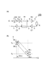
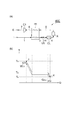
図1(a)は、第1実施形態に係る加熱モジュールを模式的に示す図である。図1(b)は、第1実施形態に係る加熱モジュールにおける熱量Qと温度Tとの関係を示すグラフである。図1(a)に示される加熱モジュール10は、入力端I、単位操作部X、出力端E、第1熱交換器H1、圧縮機C1(第1圧縮機)及び膨張機E1を備える。第1熱交換器H1は、入力端I及び出力端Eと単位操作部Xとの間に配置される。圧縮機C1は、単位操作部Xと第1熱交換器H1との間に配置される。膨張機E1は、第1熱交換器H1と入力端Iとの間に配置される。
Fig.1 (a) is a figure which shows typically the heating module which concerns on 1st Embodiment. FIG. 1B is a graph showing the relationship between the heat quantity Q and the temperature T in the heating module according to the first embodiment. The
入力端Iには、入力流体が入力される。入力流体は、単一成分を含んでもよいし、複数の成分を含んでもよい。入力流体は、気体、気液混合物のいずれであってもよい。一実施例において、入力流体は気体のブタンである。 Input fluid is input to the input terminal I. The input fluid may include a single component or a plurality of components. The input fluid may be a gas or a gas-liquid mixture. In one embodiment, the input fluid is gaseous butane.
入力端Iに入力された入力流体は、配管1を通って膨張機E1に到達する。膨張機E1は、気体の入力流体を膨張させることによって降温させる。膨張機E1は、例えばパワーリカバリータービンである。膨張機E1の膨張比は1.5〜5であることが好ましい。膨張機E1は、入力流体の温度を10〜50℃低下させることが好ましい。膨張機E1は、入力流体を断熱膨張させることができる。膨張機E1によって膨張した入力流体は、配管2を通って第1熱交換器H1に到達する。第1熱交換器H1から出力された入力流体は、配管3を通って圧縮機C1に到達する。
The input fluid input to the input end I passes through the
圧縮機C1は、気体の入力流体を圧縮させることによって昇温させる。圧縮機C1は、例えばターボ圧縮機である。圧縮機C1の圧縮比は1.5〜5であることが好ましい。圧縮機C1は、入力流体の温度を10〜50℃上昇させることが好ましい。圧縮機C1は、入力流体を断熱圧縮することができる。圧縮機C1によって圧縮された入力流体は、配管4を通って単位操作部Xに到達する。
The compressor C1 raises the temperature by compressing the gaseous input fluid. The compressor C1 is a turbo compressor, for example. The compression ratio of the compressor C1 is preferably 1.5-5. The compressor C1 preferably raises the temperature of the input fluid by 10 to 50 ° C. The compressor C1 can adiabatically compress the input fluid. The input fluid compressed by the compressor C1 reaches the unit operation unit X through the
単位操作部Xは、単位操作によって入力流体から生成される出力流体を出力する。単位操作部Xとしては、例えば反応器、分離器、膜分離器、蒸留塔、抽出装置、ガス吸収装置、吸着装置、乾燥機、加熱装置、フラッシュドラム等が挙げられる。単位操作部X中の温度は、例えば100〜300℃である。 The unit operation part X outputs the output fluid produced | generated from an input fluid by unit operation. Examples of the unit operation unit X include a reactor, a separator, a membrane separator, a distillation tower, an extraction device, a gas absorption device, an adsorption device, a dryer, a heating device, and a flash drum. The temperature in the unit operation part X is 100-300 degreeC, for example.
単位操作部Xから出力された出力流体は、配管5を通って第1熱交換器H1に到達する。第1熱交換器H1では、単位操作部Xに入力される入力流体と、単位操作部Xから出力される出力流体との間で熱交換を行う。第1熱交換器H1から出力された出力流体は、配管6を通って冷却装置CWに到達する。出力流体は、冷却装置CWによって例えば標準温度(環境温度)まで冷却される。冷却装置CWは、例えば冷却水により流体を冷却する。冷却装置CWによって冷却された出力流体は、配管7を通って出力端Eに到達する。出力端Eは出力流体を出力する。
The output fluid output from the unit operation unit X reaches the first heat exchanger H1 through the
ここで、入力端Iに入力される入力流体のエネルギーと、出力端Eから出力される出力流体のエネルギーとは、略同じであることが好ましい。例えば、出力端Eから出力された出力流体の流量、温度、圧力は、入力端Iに入力される入力流体の流量、温度、圧力と略同じであることが好ましい。これにより、加熱モジュール10を標準化されたモジュールとすることができる。
Here, it is preferable that the energy of the input fluid input to the input end I and the energy of the output fluid output from the output end E are substantially the same. For example, the flow rate, temperature and pressure of the output fluid output from the output end E are preferably substantially the same as the flow rate, temperature and pressure of the input fluid input to the input end I. Thereby, the
本実施形態に係る加熱モジュール10では、図1(b)に示されるように、温度T0の入力流体が入力端Iに入力される。その後、膨張機E1によって入力流体を膨張させることにより、入力流体を降温させる。このとき、膨張機E1により、仕事WE1としてエネルギーを回収することができる。例えば、膨張機E1としてパワーリカバリータービンを用いれば、電力を回収することができる。次に、入力流体が第1熱交換器H1を通過することによって、昇温される。続いて、圧縮機C1を用いて入力流体に仕事Wc1を加えることにより、入力流体を温度Tsまで昇温させる。このため、第1熱交換器H1に入力される出力流体の温度及び圧力を、第1熱交換器H1から出力される入力流体の温度及び圧力よりも高くすることができる。よって、第1熱交換器H1における熱交換効率を向上させることができる。さらに、出力流体が第1熱交換器H1を通過することによって、降温される。続いて、冷却装置CWによって熱量QCWが放出される。その結果、出力流体は温度T0まで降温される。
In the
上述のように、加熱モジュール10では、圧縮機C1によって入力流体を圧縮する際に所定エネルギーの仕事Wc1が必要になり、冷却装置CWによって熱量QCWが放出される。しかし、入力流体を第1熱交換器H1に入力する前に圧縮したり、第1熱交換器H1から出力された入力流体を別途ボイラー等の加熱炉で加熱する必要は殆どなくなる。
As described above, in the
図20(a)は、第1比較例に係る加熱モジュールを模式的に示す図である。図20(b)は、第1比較例に係る加熱モジュールにおける熱量Qと温度Tとの関係を示すグラフである。図20(a)に示される加熱モジュール100は、圧縮機C1及び膨張機E1を備えず、加熱炉FHを備える点で加熱モジュール10と相違している。したがって、配管3を通った入力流体は、加熱炉FHに到達し、加熱炉FHにおいて加熱された入力流体が単位操作部Xに入力される。
Fig.20 (a) is a figure which shows typically the heating module which concerns on a 1st comparative example. FIG. 20B is a graph showing the relationship between the heat quantity Q and the temperature T in the heating module according to the first comparative example. The
加熱モジュール100では、入力流体及び出力流体を圧縮せず、膨張させてもいない。このため、図20(b)に示されるように、入力流体を十分に昇温するために、加熱炉FHにおいて入力流体に熱量QFHが加えられる。この熱量QFHと同程度の熱量QCWは冷却装置CWにおいて放出される。加熱炉FHで加熱する際に必要な熱量は、圧縮機C1により入力流体又は出力流体を圧縮する際に必要な正味のエネルギー(Wc1―WE1)に比べて非常に大きい。
In the
したがって、本実施形態に係る加熱モジュール10では、省エネルギー効果が大幅に高くなる。さらに、加熱モジュール10では、単位操作部Xに入力される気体の入力流体の圧力P1を、入力端Iに入力される気体の入力流体の圧力P2と略同じにすることができる。したがって、略定圧状態で、単位操作部Xにおいて単位操作を行うことができる。
Therefore, in the
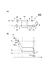
図1(c)は、第2実施形態に係る加熱モジュールを模式的に示す図である。図1(d)は、第2実施形態に係る加熱モジュールにおける熱量Qと温度Tとの関係を示すグラフである。図1(c)に示される加熱モジュール10Aは、圧縮機C1及び膨張機E1の配置を変えたこと以外は加熱モジュール10と同様の構成を有する。圧縮機C1は、単位操作部Xから出力された出力流体を圧縮する。膨張機E1は、第1熱交換器H1と出力端Eとの間に配置される。
FIG.1 (c) is a figure which shows typically the heating module which concerns on 2nd Embodiment. FIG. 1D is a graph showing the relationship between the heat quantity Q and the temperature T in the heating module according to the second embodiment. The
入力端Iに入力された入力流体は、配管1を通って第1熱交換器H1に到達する。第1熱交換器H1から出力された入力流体は、配管3を通って単位操作部Xに到達する。単位操作部Xから出力された出力流体は、配管5を通って圧縮機C1に到達する。圧縮機C1は、気体の出力流体を圧縮させることによって昇温させる。圧縮機C1によって圧縮された出力流体は、配管8を通って第1熱交換器H1に到達する。第1熱交換器H1から出力された出力流体は、配管6を通って膨張機E1に到達する。膨張機E1は、気体の出力流体を膨張させることによって降温させる。膨張機E1によって膨張した出力流体は、配管9を通って冷却装置CWに到達する。冷却装置CWによって冷却された出力流体は、配管7を通って出力端Eに到達する。
The input fluid input to the input end I passes through the
加熱モジュール10Aでは、図1に示される加熱モジュール10と同様の作用効果が得られるので省エネルギー効果が大幅に高くなる。さらに、加熱モジュール10Aでは、単位操作部Xに入力される気体の入力流体の圧力P1を、入力端Iに入力される気体の入力流体の圧力P2と略同じにすることができる。したがって、略定圧状態で、単位操作部Xにおいて単位操作を行うことができる。
In the
図2(a)は、第3実施形態に係る加熱モジュールを模式的に示す図である。図2(b)は、第3実施形態に係る加熱モジュールにおける熱量Qと温度Tとの関係を示すグラフである。図2(a)に示される加熱モジュール10Bは、圧縮機C1の配置を変えたこと以外は加熱モジュール10と同様の構成を有する。圧縮機C1は、単位操作部Xから出力された出力流体を圧縮する。
Fig.2 (a) is a figure which shows typically the heating module which concerns on 3rd Embodiment. FIG. 2B is a graph showing the relationship between the heat quantity Q and the temperature T in the heating module according to the third embodiment. The
第1熱交換器H1から出力された入力流体は、配管3を通って単位操作部Xに到達する。単位操作部Xから出力された出力流体は、配管5を通って圧縮機C1に到達する。圧縮機C1によって圧縮された出力流体は、配管8を通って第1熱交換器H1に到達する。
The input fluid output from the first heat exchanger H1 reaches the unit operation unit X through the
加熱モジュール10Bでは、図1に示される加熱モジュール10と同様の作用効果が得られるので省エネルギー効果が大幅に高くなる。さらに、加熱モジュール10Bでは、単位操作部Xに入力される気体の入力流体の圧力P1を、入力端Iに入力される気体の入力流体の圧力P2よりも小さくすることができる。したがって、減圧状態で、単位操作部Xにおいて単位操作を行うことができる。
In the
図3(a)は、第4実施形態に係る加熱モジュールを模式的に示す図である。図3(b)は、第4実施形態に係る加熱モジュールにおける熱量Qと温度Tとの関係を示すグラフである。図3(a)に示される加熱モジュール10Cは、加熱モジュール10の構成に加えて、圧縮機C2及び膨張機E2を備える。加熱モジュール10Cは、加熱モジュール10と加熱モジュール10Aとを組み合わせたような構成を有している。圧縮機C2は、圧縮機C1と同様のものであり、出力流体を圧縮して昇温させる。膨張機E2は、膨張機E1と同様のものであり、第1熱交換器H1と出力端Eとの間に配置され、出力流体を膨張させて降温させる。
Fig.3 (a) is a figure which shows typically the heating module which concerns on 4th Embodiment. FIG. 3B is a graph showing the relationship between the heat quantity Q and the temperature T in the heating module according to the fourth embodiment. A
本実施形態に係る加熱モジュール10Cでは、図3(b)に示されるように、膨張機E1により仕事WE1としてエネルギーを回収すると共に膨張機E2により仕事WE2としてエネルギーを回収することができる。一方、圧縮機C1によって入力流体を圧縮する際に所定エネルギーの仕事Wc1が必要になり、圧縮機C2によって出力流体を圧縮する際に所定エネルギーの仕事Wc2が必要になる。さらに、冷却装置CWによって熱量QCWが放出される。
In the
加熱モジュール10Cでは、図1に示される加熱モジュール10と図1(c)に示される加熱モジュール10Aの両方の作用効果が得られるので省エネルギー効果が大幅に高くなる。さらに、加熱モジュール10Cでは、加熱モジュール10,10Aと同様に、単位操作部Xに入力される気体の入力流体の圧力P1を、入力端Iに入力される気体の入力流体の圧力P2と略同じにすることができる。
In the
図4は、第5実施形態に係る加熱モジュールを模式的に示す図である。図4に示される加熱モジュール10Dは、加熱モジュール10の構成に加えて、第2熱交換器H2及び圧縮機C3(第2圧縮機)を更に備える。圧縮機C3は、圧縮機C1と同様のものであり、入力流体を圧縮して昇温させる。
FIG. 4 is a diagram schematically showing a heating module according to the fifth embodiment. The
第2熱交換器H2は、単位操作部Xと圧縮機C1との間に配置され、単位操作部Xに入力される入力流体と、単位操作部Xから出力される出力流体との間で熱交換を行う。圧縮機C3は、単位操作部Xと第2熱交換器H2との間に配置され、気体の入力流体を圧縮することによって昇温させる。圧縮機C3を配管5の途中に配置して、気体の出力流体を圧縮することによって昇温させてもよい。
The second heat exchanger H2 is disposed between the unit operation unit X and the compressor C1, and generates heat between the input fluid input to the unit operation unit X and the output fluid output from the unit operation unit X. Exchange. The compressor C3 is arrange | positioned between the unit operation part X and the 2nd heat exchanger H2, and it heats up by compressing a gaseous input fluid. The temperature may be increased by arranging the compressor C3 in the middle of the
圧縮機C1によって圧縮された入力流体は、配管4を通って第2熱交換器H2に入力される。第2熱交換器H2を通過した入力流体は、配管11を通って圧縮機C3に入力される。圧縮機C3によって圧縮された入力流体は、配管12を通って単位操作部Xに入力される。単位操作部Xから出力された出力流体は、配管5を通って第2熱交換器H2に入力される。第2熱交換器H2を通過した出力流体は、配管13を通って第1熱交換器H1に入力される。
The input fluid compressed by the compressor C1 is input to the second heat exchanger H2 through the
加熱モジュール10Dでは、図1に示される加熱モジュール10と同様の作用効果が得られるので省エネルギー効果が大幅に高くなる。さらに、例えば圧縮機C3によって入力流体を僅かに圧縮して温度調整することができる。このため、第1熱交換器H1だけを用いた場合の熱交換効率に比べて、第1熱交換器H1及び第2熱交換器H2のトータルの熱交換効率を大きくすることができる。
In the
より具体的には、図1(b)において、第1熱交換器H1中で入力流体の温度が上昇するに連れて、入力流体と出力流体との温度差ΔTが徐々に大きくなっていく場合に、圧縮機C3によって入力流体を圧縮すると、温度差ΔTを小さくすることができる。そのため、第1熱交換器H1及び第2熱交換器H2中において、入力流体の温度上昇線と出力流体の温度下降線とを略平行にすることができる。よって、熱交換効率が向上する。
(気体を用いた冷却モジュール)
More specifically, in FIG. 1B, the temperature difference ΔT between the input fluid and the output fluid gradually increases as the temperature of the input fluid rises in the first heat exchanger H1. In addition, when the input fluid is compressed by the compressor C3, the temperature difference ΔT can be reduced. Therefore, in the first heat exchanger H1 and the second heat exchanger H2, the temperature rise line of the input fluid and the temperature fall line of the output fluid can be made substantially parallel. Therefore, the heat exchange efficiency is improved.
(Cooling module using gas)
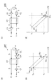
図5(a)は、第1実施形態に係る冷却モジュールを模式的に示す図である。図5(b)は、第1実施形態に係る冷却モジュールにおける熱量Qと温度Tとの関係を示すグラフである。図5(a)に示される冷却モジュール20は、入力端I、単位操作部X、出力端E、第1熱交換器H1、圧縮機C1及び膨張機E1を備える。圧縮機C1は、入力端Iと第1熱交換器H1との間に配置される。膨張機E1は、第1熱交換器H1と単位操作部Xとの間に配置される。
FIG. 5A is a diagram schematically showing the cooling module according to the first embodiment. FIG. 5B is a graph showing the relationship between the amount of heat Q and the temperature T in the cooling module according to the first embodiment. The
入力端Iには、入力流体が入力される。入力流体は、単一成分を含んでもよいし、複数の成分を含んでもよい。入力流体は、気体、気液混合物のいずれであってもよい。一実施例において、入力流体は気体のブタンである。 Input fluid is input to the input terminal I. The input fluid may include a single component or a plurality of components. The input fluid may be a gas or a gas-liquid mixture. In one embodiment, the input fluid is gaseous butane.
入力端Iに入力された入力流体は、配管1を通って圧縮機C1に到達する。圧縮機C1によって圧縮された入力流体は、配管2を通って第1熱交換器H1に到達する。第1熱交換器H1から出力された入力流体は、配管3を通って単位操作部Xに到達する。
The input fluid input to the input end I reaches the compressor C <b> 1 through the
単位操作部Xは、単位操作によって入力流体から生成される出力流体を出力する。単位操作部Xとしては、例えば反応器、分離器、膜分離器、抽出装置、ガス吸収装置、吸着装置、冷却器、フラッシュドラム等が挙げられる。 The unit operation part X outputs the output fluid produced | generated from an input fluid by unit operation. Examples of the unit operation unit X include a reactor, a separator, a membrane separator, an extraction device, a gas absorption device, an adsorption device, a cooler, and a flash drum.
単位操作部Xから出力された出力流体は、配管5を通って膨張機E1に到達する。膨張機E1によって膨張した出力流体は、配管8を通って第1熱交換器H1に到達する。第1熱交換器H1から出力された出力流体は、配管6を通って冷却装置CWに到達する。冷却装置CWによって冷却された出力流体は、配管7を通って出力端Eに到達する。出力端Eは出力流体を出力する。
The output fluid output from the unit operation unit X reaches the expander E1 through the
ここで、入力端Iに入力される入力流体のエネルギーと、出力端Eから出力される出力流体のエネルギーとは、略同じであることが好ましい。例えば、出力端Eから出力された出力流体の流量、温度、圧力は、入力端Iに入力される入力流体の流量、温度、圧力と略同じであることが好ましい。これにより、冷却モジュール20を標準化されたモジュールとすることができる。
Here, it is preferable that the energy of the input fluid input to the input end I and the energy of the output fluid output from the output end E are substantially the same. For example, the flow rate, temperature and pressure of the output fluid output from the output end E are preferably substantially the same as the flow rate, temperature and pressure of the input fluid input to the input end I. Thereby, the
本実施形態に係る冷却モジュール20では、図5(b)に示されるように、温度T0の入力流体が入力端Iに入力される。その後、圧縮機C1を用いて仕事Wc1を加えることにより、入力流体を圧縮する。これにより、入力流体を昇温させる。次に、入力流体が第1熱交換器H1を通過することによって、降温される。続いて、膨張機E1を用いて出力流体を膨張させることにより、出力流体を温度Tsまで降温させる。このため、第1熱交換器H1に入力される出力流体の温度及び圧力を、第1熱交換器H1から出力される入力流体の温度及び圧力よりも低くすることができる。よって、第1熱交換器H1における熱交換効率を向上させることができる。なお、膨張機E1により、仕事WE1としてエネルギーを回収することができる。さらに、出力流体が第1熱交換器H1を通過することによって、昇温される。続いて、冷却装置CWによって熱量QCWが放出される。その結果、出力流体は温度T0まで降温される。
In the
上述のように、冷却モジュール20では、圧縮機C1によって入力流体を圧縮する際に所定エネルギーの仕事Wc1が必要になり、冷却装置CWによって熱量QCWが放出される。しかし、第1熱交換器H1から出力された入力流体を別途冷却器で冷却したり、第1熱交換器H1から出力された出力流体を別途冷却する必要は殆どなくなる。別途冷却する際に必要なエネルギーは、圧縮機C1により入力流体を圧縮する際に必要な正味のエネルギー(Wc1―WE1)に比べて非常に大きい。
As described above, in the
したがって、冷却モジュール20では、省エネルギー効果が大幅に高くなる。さらに、冷却モジュール20では、単位操作部Xに入力される気体の入力流体の圧力P1を、入力端Iに入力される気体の入力流体の圧力P2よりも大きくすることができる。したがって、昇圧状態で、単位操作部Xにおいて単位操作を行うことができる。
Therefore, in the
図6(a)は、第2実施形態に係る冷却モジュールを模式的に示す図である。図6(b)は、第2実施形態に係る冷却モジュールにおける熱量Qと温度Tとの関係を示すグラフである。図6(a)に示される冷却モジュール20Aは、膨張機E1の配置を変えたこと以外は冷却モジュール20と同様の構成を有する。膨張機E1は、単位操作部Xから出力された出力流体を膨張させる。
FIG. 6A is a diagram schematically illustrating a cooling module according to the second embodiment. FIG. 6B is a graph showing the relationship between the heat quantity Q and the temperature T in the cooling module according to the second embodiment. The
第1熱交換器H1から出力された入力流体は、配管3を通って膨張機E1に到達する。膨張機E1は、気体の入力流体を膨張させることによって降温させる。膨張機E1によって膨張した入力流体は、配管4を通って単位操作部Xに到達する。単位操作部Xから出力された出力流体は、配管5を通って第1熱交換器H1に到達する。
The input fluid output from the first heat exchanger H1 passes through the
冷却モジュール20Aでは、図5(a)に示される冷却モジュール20と同様の作用効果が得られるので省エネルギー効果が大幅に高くなる。さらに、冷却モジュール20Aでは、単位操作部Xに入力される気体の入力流体の圧力P1を、入力端Iに入力される気体の入力流体の圧力P2と略同じにすることができる。したがって、略定圧状態で、単位操作部Xにおいて単位操作を行うことができる。
In the
図6(c)は、第3実施形態に係る冷却モジュールを模式的に示す図である。図6(d)は、第3実施形態に係る冷却モジュールにおける熱量Qと温度Tとの関係を示すグラフである。図6(c)に示される冷却モジュール20Bは、圧縮機C1の配置を変えたこと以外は冷却モジュール20と同様の構成を有する。圧縮機C1は、第1熱交換器H1と出力端Eとの間に配置される。
FIG. 6C is a diagram schematically illustrating the cooling module according to the third embodiment. FIG. 6D is a graph showing the relationship between the heat quantity Q and the temperature T in the cooling module according to the third embodiment. The
入力端Iに入力された入力流体は、配管1を通って第1熱交換器H1に到達する。第1熱交換器H1から出力された出力流体は、配管6を通って圧縮機C1に到達する。圧縮機C1は、気体の出力流体を圧縮することによって昇温させる。圧縮機C1によって圧縮された出力流体は、配管9を通って冷却装置CWに到達する。
The input fluid input to the input end I passes through the
冷却モジュール20Bでは、図5(a)に示される冷却モジュール20と同様の作用効果が得られるので省エネルギー効果が大幅に高くなる。さらに、冷却モジュール20Bでは、単位操作部Xに入力される気体の入力流体の圧力P1を、入力端Iに入力される気体の入力流体の圧力P2と略同じにすることができる。したがって、略定圧状態で、単位操作部Xにおいて単位操作を行うことができる。
In the
図7(a)は、第4実施形態に係る冷却モジュールを模式的に示す図である。図7(b)は、第4実施形態に係る冷却モジュールにおける熱量Qと温度Tとの関係を示すグラフである。図7(a)に示される冷却モジュール20Cは、膨張機E1の配置を変えたこと以外は冷却モジュール20Bと同様の構成を有する。膨張機E1は、第1熱交換器H1から出力された入力流体を膨張させる。
Fig.7 (a) is a figure which shows typically the cooling module which concerns on 4th Embodiment. FIG. 7B is a graph showing the relationship between the heat quantity Q and the temperature T in the cooling module according to the fourth embodiment. The
第1熱交換器H1から出力された入力流体は、配管3を通って膨張機E1に到達する。膨張機E1は、気体の入力流体を膨張させることによって降温させる。膨張機E1によって膨張した入力流体は、配管4を通って単位操作部Xに到達する。単位操作部Xから出力された出力流体は、配管5を通って第1熱交換器H1に到達する。
The input fluid output from the first heat exchanger H1 passes through the
冷却モジュール20Cでは、図5(a)に示される冷却モジュール20と同様の作用効果が得られるので省エネルギー効果が大幅に高くなる。さらに、冷却モジュール20Cでは、単位操作部Xに入力される気体の入力流体の圧力P1を、入力端Iに入力される気体の入力流体の圧力P2よりも小さくすることができる。したがって、減圧状態で、単位操作部Xにおいて単位操作を行うことができる。
In the
図8(a)は、第5実施形態に係る冷却モジュールを模式的に示す図である。図8(b)は、第5実施形態に係る冷却モジュールにおける熱量Qと温度Tとの関係を示すグラフである。図8(a)に示される冷却モジュール20Dは、冷却モジュール20Aの構成に加えて、圧縮機C2及び膨張機E2を備える。冷却モジュール20Dは、冷却モジュール20Aと冷却モジュール20Bとを組み合わせたような構成を有している。
FIG. 8A is a diagram schematically showing a cooling module according to the fifth embodiment. FIG. 8B is a graph showing the relationship between the heat quantity Q and the temperature T in the cooling module according to the fifth embodiment. The
本実施形態に係る冷却モジュール20Dでは、図8(b)に示されるように、膨張機E1により仕事WE1としてエネルギーを回収すると共に膨張機E2により仕事WE2としてエネルギーを回収することができる。一方、圧縮機C1によって入力流体を圧縮する際に所定エネルギーの仕事Wc1が必要になり、圧縮機C2によって出力流体を圧縮する際に所定エネルギーの仕事Wc2が必要になる。さらに、冷却装置CWによって熱量QCWが放出される。
In the
冷却モジュール20Dでは、図6(a)に示される冷却モジュール20Aと図6(c)に示される冷却モジュール20Bの両方の作用効果が得られるので省エネルギー効果が大幅に高くなる。さらに、冷却モジュール20Dでは、冷却モジュール20A,20Bと同様に、単位操作部Xに入力される気体の入力流体の圧力P1を、入力端Iに入力される気体の入力流体の圧力P2と略同じにすることができる。
In the
図9(a)は、第6実施形態に係る冷却モジュールを模式的に示す図である。図9(b)は、第6実施形態に係る冷却モジュールにおける熱量Qと温度Tとの関係を示すグラフである。図9(a)に示される冷却モジュール20Eは、冷却モジュール20の構成に加えて、冷却器CLを更に備え、冷却装置CWを備えていない。冷却器CLは、第1熱交換器H1と単位操作部Xとの間に配置される。
Fig.9 (a) is a figure which shows typically the cooling module which concerns on 6th Embodiment. FIG. 9B is a graph showing the relationship between the heat quantity Q and the temperature T in the cooling module according to the sixth embodiment. The
第1熱交換器H1から出力された入力流体は、配管3を通って冷却器CLに到達する。冷却器CLは、液体の入力流体を温度Tsまで冷却する。冷却器CLによって冷却された入力流体は、配管4を通って単位操作部Xに到達する。第1熱交換器H1から出力された出力流体は、配管6を通って出力端Eに到達する。
The input fluid output from the first heat exchanger H1 reaches the cooler CL through the
冷却モジュール20Eでは、図5(a)に示される冷却モジュール20と同様の作用効果が得られるので省エネルギー効果が大幅に高くなる。また、冷却装置CWによる熱量QCWが放出されずに、冷却器CLによって熱量QCLが放出される。さらに、冷却モジュール20Eでは、単位操作部Xに入力される気体の入力流体の圧力P1を、入力端Iに入力される気体の入力流体の圧力P2よりも大きくすることができる。したがって、昇圧状態で、単位操作部Xにおいて単位操作を行うことができる。
In the
図10(a)は、第7実施形態に係る冷却モジュールを模式的に示す図である。図10(b)は、第7実施形態に係る冷却モジュールにおける熱量Qと温度Tとの関係を示すグラフである。図10(a)に示される冷却モジュール20Fは、冷却モジュール20Aの構成に加えて、冷却器CLを更に備え、冷却装置CWを備えていない。冷却器CLは、膨張機E1と単位操作部Xとの間に配置される。
Fig.10 (a) is a figure which shows typically the cooling module which concerns on 7th Embodiment. FIG. 10B is a graph showing the relationship between the heat quantity Q and the temperature T in the cooling module according to the seventh embodiment. A
膨張機E1によって圧縮された入力流体は、配管14を通って冷却器CLに到達する。冷却器CLは、液体の入力流体を温度Tsまで冷却する。冷却器CLによって冷却された入力流体は、配管4を通って単位操作部Xに到達する。
The input fluid compressed by the expander E1 reaches the cooler CL through the
冷却モジュール20Fでは、図6(a)に示される冷却モジュール20Aと同様の作用効果が得られるので省エネルギー効果が大幅に高くなる。また、冷却装置CWによる熱量QCWが放出されずに、冷却器CLによって熱量QCLが放出される。さらに、冷却モジュール20Fでは、単位操作部Xに入力される気体の入力流体の圧力P1を、入力端Iに入力される気体の入力流体の圧力P2と略同じにすることができる。したがって、略定圧状態で、単位操作部Xにおいて単位操作を行うことができる。
In the
図10(c)は、第8実施形態に係る冷却モジュールを模式的に示す図である。図10(d)は、第8実施形態に係る冷却モジュールにおける熱量Qと温度Tとの関係を示すグラフである。図10(c)に示される冷却モジュール20Gは、冷却モジュール20Bの構成に加えて、冷却器CLを更に備え、冷却装置CWを備えていない。冷却器CLは、第1熱交換器H1と単位操作部Xとの間に配置される。
FIG. 10C is a diagram schematically illustrating the cooling module according to the eighth embodiment. FIG. 10D is a graph showing the relationship between the heat quantity Q and the temperature T in the cooling module according to the eighth embodiment. The
第1熱交換器H1から出力された入力流体は、配管3を通って冷却器CLに到達する。冷却器CLは、液体の入力流体を温度Tsまで冷却する。冷却器CLによって冷却された入力流体は、配管4を通って単位操作部Xに到達する。
The input fluid output from the first heat exchanger H1 reaches the cooler CL through the
冷却モジュール20Gでは、図6(b)に示される冷却モジュール20Bと同様の作用効果が得られるので省エネルギー効果が大幅に高くなる。また、冷却装置CWによる熱量QCWが放出されずに、冷却器CLによって熱量QCLが放出される。さらに、冷却モジュール20Gでは、単位操作部Xに入力される気体の入力流体の圧力P1を、入力端Iに入力される気体の入力流体の圧力P2と略同じにすることができる。したがって、略定圧状態で、単位操作部Xにおいて単位操作を行うことができる。
In the
図11(a)は、第9実施形態に係る冷却モジュールを模式的に示す図である。図11(b)は、第9実施形態に係る冷却モジュールにおける熱量Qと温度Tとの関係を示すグラフである。図11(a)に示される冷却モジュール20Hは、冷却モジュール20Cの構成に加えて、冷却器CLを更に備え、冷却装置CWを備えていない。冷却器CLは、膨張機E1と単位操作部Xとの間に配置される。
FIG. 11A is a diagram schematically showing a cooling module according to the ninth embodiment. FIG. 11B is a graph showing the relationship between the heat quantity Q and the temperature T in the cooling module according to the ninth embodiment. In addition to the configuration of the
膨張機E1によって圧縮された入力流体は、配管14を通って冷却器CLに到達する。冷却器CLは、液体の入力流体を温度Tsまで冷却する。冷却器CLによって冷却された入力流体は、配管4を通って単位操作部Xに到達する。
The input fluid compressed by the expander E1 reaches the cooler CL through the
冷却モジュール20Hでは、図7(a)に示される冷却モジュール20Cと同様の作用効果が得られるので省エネルギー効果が大幅に高くなる。また、冷却装置CWによる熱量QCWが放出されずに、冷却器CLによって熱量QCLが放出される。さらに、冷却モジュール20Hでは、単位操作部Xに入力される気体の入力流体の圧力P1を、入力端Iに入力される気体の入力流体の圧力P2よりも小さくすることができる。したがって、減圧状態で、単位操作部Xにおいて単位操作を行うことができる。
In the
なお、図8に示される冷却モジュール20Dの構成に冷却器CLを加えて、冷却装置CWを除去してもよい。この場合、冷却器CLは、膨張機E1と単位操作部Xとの間に配置される。
(液体から気体への相変化を用いた加熱モジュール)
Note that the cooling device CW may be removed by adding a cooler CL to the configuration of the
(Heating module using phase change from liquid to gas)
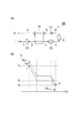
図12(a)は、第6実施形態に係る加熱モジュールを模式的に示す図である。図12(b)は、第6実施形態に係る加熱モジュールにおける熱量Qと温度Tとの関係を示すグラフである。図12(a)に示される加熱モジュール30は、入力端I、単位操作部X、出力端E、第1熱交換器H1及び圧縮機C1を備える。圧縮機C1は、単位操作部Xと第1熱交換器H1との間に配置される。
Fig.12 (a) is a figure which shows typically the heating module which concerns on 6th Embodiment. FIG. 12B is a graph showing the relationship between the heat quantity Q and the temperature T in the heating module according to the sixth embodiment. The
入力端Iには、入力流体が入力される。入力流体は、単一成分を含んでもよいし、複数の成分を含んでもよい。入力流体は、液体、気液混合物のいずれであってもよい。一実施例において、入力流体は液体のベンゼンである。 Input fluid is input to the input terminal I. The input fluid may include a single component or a plurality of components. The input fluid may be a liquid or a gas-liquid mixture. In one embodiment, the input fluid is liquid benzene.
入力端Iに入力された入力流体は、配管1を通って第1熱交換器H1に到達する。第1熱交換器H1から出力された入力流体は、配管3を通って圧縮機C1に到達する。圧縮機C1は、気体の入力流体を圧縮させることによって昇温させる。圧縮機C1によって圧縮された入力流体は、配管4を通って単位操作部Xに到達する。
The input fluid input to the input end I passes through the
単位操作部Xから出力された出力流体は、配管5を通って第1熱交換器H1に到達する。第1熱交換器H1から出力された出力流体は、配管6を通ってバルブV1に到達する。バルブV1は、第1熱交換器H1と出力端Eとの間に配置されており、液体の出力流体を膨張させる。バルブV1によって膨張した液体の出力流体は、配管9を通って冷却装置CWに到達する。出力流体は、冷却装置CWによって例えば標準温度(環境温度)まで冷却される。冷却装置CWによって冷却された出力流体は、配管7を通って出力端Eに到達する。出力端Eは出力流体を出力する。
The output fluid output from the unit operation unit X reaches the first heat exchanger H1 through the
第1熱交換器H1は、液体の入力流体を気化させて気体の入力流体を出力すると共に、気体の出力流体を液化させて液体の出力流体を出力する。 The first heat exchanger H1 vaporizes the liquid input fluid to output the gas input fluid, and liquefies the gas output fluid to output the liquid output fluid.
ここで、入力端Iに入力される入力流体のエネルギーと、出力端Eから出力される出力流体のエネルギーとは、略同じであることが好ましい。例えば、出力端Eから出力された出力流体の流量、温度、圧力は、入力端Iに入力される入力流体の流量、温度、圧力と略同じであることが好ましい。これにより、加熱モジュール30を標準化されたモジュールとすることができる。
Here, it is preferable that the energy of the input fluid input to the input end I and the energy of the output fluid output from the output end E are substantially the same. For example, the flow rate, temperature and pressure of the output fluid output from the output end E are preferably substantially the same as the flow rate, temperature and pressure of the input fluid input to the input end I. Thereby, the
本実施形態に係る加熱モジュール30では、第6実施形態に係る加熱モジュールを模式的に示す図である。図12(b)は、第6実施形態に係る加熱モジュールにおける熱量Qと温度Tとの関係を示すグラフである。(b)に示されるように、温度T0の液体の入力流体が入力端Iに入力される。その後、入力流体が第1熱交換器H1を通過することによって、沸点Tbよりも高い温度まで昇温される。その結果、気体の入力流体が第1熱交換器H1から出力される。続いて、圧縮機C1を用いて入力流体に仕事Wc1を加えることにより、入力流体を温度Tsまで昇温させる。このため、第1熱交換器H1に入力される出力流体の温度及び圧力を、第1熱交換器H1から出力される入力流体の温度及び圧力よりも高くすることができる。よって、第1熱交換器H1における熱交換効率を向上させることができる。さらに、出力流体が第1熱交換器H1を通過することによって、沸点Tbよりも低い温度まで降温される。その結果、液体の出力流体が第1熱交換器H1から出力される。続いて、冷却装置CWによって熱量QCWが放出される。その結果、出力流体は温度T0まで降温される。
In the
上述のように、加熱モジュール30では、圧縮機C1によって入力流体を圧縮する際に所定エネルギーの仕事Wc1が必要になり、冷却装置CWによって熱量QCWが放出される。しかし、入力流体を第1熱交換器H1に入力する前に圧縮したり、第1熱交換器H1から出力された入力流体を別途ボイラー等の加熱炉で加熱する必要は殆どなくなる。さらに、加熱モジュール30では、第1熱交換器H1において、気体の出力流体が液化する際の潜熱を、入力流体によって回収することができる。
As described above, in the
図21(a)は、第2比較例に係る加熱モジュールを模式的に示す図である。図21(b)は、第2比較例に係る加熱モジュールにおける熱量Qと温度Tとの関係を示すグラフである。図21(a)に示される加熱モジュール100Aは、圧縮機C1及びバルブV1を備えず、加熱炉FHを備える点で加熱モジュール30と相違している。したがって、配管3を通った入力流体は、加熱炉FHに到達し、加熱炉FHにおいて加熱された入力流体が単位操作部Xに入力される。
FIG. 21A is a diagram schematically showing a heating module according to the second comparative example. FIG. 21B is a graph showing the relationship between the amount of heat Q and the temperature T in the heating module according to the second comparative example. The
加熱モジュール100Aでは、入力流体及び出力流体を圧縮せず、膨張させてもいない。このため、図21(b)に示されるように、入力流体を十分に昇温するために、加熱炉FHにおいて入力流体に熱量QFHが加えられる。この熱量QFHと同程度の熱量QCWは冷却装置CWにおいて放出される。加熱炉FHで加熱する際に必要な熱量は、圧縮機C1により入力流体又は出力流体を圧縮する際に必要な所定エネルギーの仕事Wc1に比べて非常に大きい。さらに、加熱モジュール100Aでは、第1熱交換器H1において、気体の出力流体が液化する際の潜熱を、殆ど回収することができない。
In the
したがって、加熱モジュール30では、省エネルギー効果が大幅に高くなる。さらに、加熱モジュール30では、単位操作部Xに入力される気体の入力流体の圧力P1を、入力端Iに入力される液体の入力流体の圧力P2よりも大きくすることができる。
Therefore, in the
図13(a)は、第7実施形態に係る加熱モジュールを模式的に示す図である。図13(b)は、第7実施形態に係る加熱モジュールにおける熱量Qと温度Tとの関係を示すグラフである。図13(a)に示される加熱モジュール30Aは、バルブV1の配置を変えたこと以外は加熱モジュール30と同様の構成を有する。バルブV1は、第1熱交換器H1と入力端Iとの間に配置される。
FIG. 13A is a diagram schematically showing a heating module according to the seventh embodiment. FIG. 13B is a graph showing the relationship between the heat quantity Q and the temperature T in the heating module according to the seventh embodiment. The
入力端Iに入力された入力流体は、配管1を通ってバルブV1に到達する。バルブV1は、液体の入力流体を膨張させる。バルブV1から出力された入力流体は、配管2を通って第1熱交換器H1に到達する。第1熱交換器H1から出力された出力流体は、配管6を通って冷却装置CWに到達する。
The input fluid input to the input end I passes through the
加熱モジュール30Aでは、図12(a)に示される加熱モジュール30と同様の作用効果が得られるので省エネルギー効果が大幅に高くなる。さらに、加熱モジュール30Aでは、単位操作部Xに入力される気体の入力流体の圧力P1を、入力端Iに入力される液体の入力流体の圧力P2と略同じにすることができる。
In the
図13(c)は、第8実施形態に係る加熱モジュールを模式的に示す図である。図13(d)は、第8実施形態に係る加熱モジュールにおける熱量Qと温度Tとの関係を示すグラフである。図13(c)に示される加熱モジュール30Bは、圧縮機C1の配置を変えたこと以外は加熱モジュール30と同様の構成を有する。圧縮機C1は、単位操作部Xから出力された出力流体を圧縮する。
FIG.13 (c) is a figure which shows typically the heating module which concerns on 8th Embodiment. FIG. 13D is a graph showing the relationship between the heat quantity Q and the temperature T in the heating module according to the eighth embodiment. The
第1熱交換器H1から出力された入力流体は、配管3を通って圧縮機C1に到達する。圧縮機C1によって圧縮された入力流体は、配管4を通って単位操作部Xに到達する。単位操作部Xから出力された出力流体は、配管5を通って第1熱交換器H1に到達する。
The input fluid output from the first heat exchanger H1 passes through the
加熱モジュール30Bでは、図12(a)に示される加熱モジュール30と同様の作用効果が得られるので省エネルギー効果が大幅に高くなる。さらに、加熱モジュール30Bでは、単位操作部Xに入力される気体の入力流体の圧力P1を、入力端Iに入力される液体の入力流体の圧力P2と略同じにすることができる。
In the
図14(a)は、第9実施形態に係る加熱モジュールを模式的に示す図である。図14(b)は、第9実施形態に係る加熱モジュールにおける熱量Qと温度Tとの関係を示すグラフである。図14(a)に示される加熱モジュール30Cは、圧縮機C1の配置を変えたこと以外は加熱モジュール30Aと同様の構成を有する。圧縮機C1は、単位操作部Xから出力された出力流体を圧縮する。
FIG. 14A is a diagram schematically showing a heating module according to the ninth embodiment. FIG. 14B is a graph showing the relationship between the heat quantity Q and the temperature T in the heating module according to the ninth embodiment. The
第1熱交換器H1から出力された入力流体は、配管3を通って単位操作部Xに到達する。単位操作部Xから出力された出力流体は、配管5を通って圧縮機C1に到達する。圧縮機C1によって圧縮された出力流体は、配管8を通って第1熱交換器H1に到達する。
The input fluid output from the first heat exchanger H1 reaches the unit operation unit X through the
加熱モジュール30Cでは、図13(a)に示される加熱モジュール30Aと同様の作用効果が得られるので省エネルギー効果が大幅に高くなる。さらに、加熱モジュール30Cでは、単位操作部Xに入力される気体の入力流体の圧力P1を、入力端Iに入力される液体の入力流体の圧力P2よりも小さくすることができる。
In the
図15(a)は、第10実施形態に係る加熱モジュールを模式的に示す図である。図15(b)は、第10実施形態に係る加熱モジュールにおける熱量Qと温度Tとの関係を示すグラフである。図15(a)に示される加熱モジュール30Dは、加熱モジュール30Aの構成に加えて、圧縮機C2及びバルブV2を備える。加熱モジュール30Dは、加熱モジュール30Aと加熱モジュール30Bとを組み合わせたような構成を有している。バルブV2は、バルブV1と同様のものであり、出力流体を膨張させる。
FIG. 15A is a diagram schematically showing a heating module according to the tenth embodiment. FIG. 15B is a graph showing the relationship between the heat quantity Q and the temperature T in the heating module according to the tenth embodiment. A
本実施形態に係る加熱モジュール30Dでは、図15(b)に示されるように、圧縮機C1によって入力流体を圧縮する際に所定エネルギーの仕事Wc1が必要になり、圧縮機C2によって出力流体を圧縮する際に所定エネルギーの仕事Wc2が必要になる。さらに、冷却装置CWによって熱量QCWが放出される。
In the
加熱モジュール30Dでは、図13(a)に示される加熱モジュール30Aと図13(c)に示される加熱モジュール30Bの両方の作用効果が得られるので省エネルギー効果が大幅に高くなる。さらに、加熱モジュール30Dでは、加熱モジュール30A,30Bと同様に、単位操作部Xに入力される気体の入力流体の圧力P1を、入力端Iに入力される気体の入力流体の圧力P2と略同じにすることができる。
(気体から液体への相変化を用いた冷却モジュール)
In the
(Cooling module using phase change from gas to liquid)
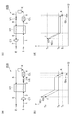
図16(a)は、第10実施形態に係る冷却モジュールを模式的に示す図である。図16(b)は、第10実施形態に係る冷却モジュールにおける熱量Qと温度Tとの関係を示すグラフである。図16(a)に示される冷却モジュール40は、入力端I、単位操作部X、出力端E、第1熱交換器H1、圧縮機C1、冷却器CL及びバルブV1を備える。圧縮機C1は、入力端Iと第1熱交換器H1との間に配置される。冷却器CLは、単位操作部Xと第1熱交換器H1との間に配置され、液体の入力流体を冷却する。バルブV1は、単位操作部Xと第1熱交換器H1との間に配置され、液体の出力流体を膨張させる。
FIG. 16A is a diagram schematically illustrating a cooling module according to the tenth embodiment. FIG. 16B is a graph showing the relationship between the heat quantity Q and the temperature T in the cooling module according to the tenth embodiment. The
入力端Iには、入力流体が入力される。入力流体は、単一成分を含んでもよいし、複数の成分を含んでもよい。入力流体は、気体、気液混合物のいずれであってもよい。一実施例において、入力流体は気体のベンゼンである。 Input fluid is input to the input terminal I. The input fluid may include a single component or a plurality of components. The input fluid may be a gas or a gas-liquid mixture. In one embodiment, the input fluid is gaseous benzene.
入力端Iに入力された入力流体は、配管1を通って圧縮機C1に到達する。圧縮機C1は、気体の入力流体を圧縮させることによって昇温させる。圧縮機C1によって圧縮された入力流体は、配管2を通って第1熱交換器H1に到達する。第1熱交換器H1から出力された入力流体は、配管3を通って冷却器CLに到達する。冷却器CLは、液体の入力流体を温度Tsまで冷却する。冷却器CLによって冷却された入力流体は、配管4を通って単位操作部Xに到達する。
The input fluid input to the input end I reaches the compressor C <b> 1 through the
単位操作部Xから出力された出力流体は、配管5を通ってバルブV1に到達する。バルブV1によって膨張された液体の出力流体は、配管8を通って第1熱交換器H1に到達する。第1熱交換器H1から出力された出力流体は、配管6を通って出力端Eに到達する。
The output fluid output from the unit operation unit X passes through the
第1熱交換器H1は、気体の入力流体を液化させて液体の入力流体を出力すると共に、液体の出力流体を気化させて気体の出力流体を出力する。 The first heat exchanger H1 liquefies the gas input fluid and outputs the liquid input fluid, and also vaporizes the liquid output fluid and outputs the gas output fluid.
ここで、入力端Iに入力される入力流体のエネルギーと、出力端Eから出力される出力流体のエネルギーとは、略同じであることが好ましい。例えば、出力端Eから出力された出力流体の流量、温度、圧力は、入力端Iに入力される入力流体の流量、温度、圧力と略同じであることが好ましい。これにより、冷却モジュール40を標準化されたモジュールとすることができる。
Here, it is preferable that the energy of the input fluid input to the input end I and the energy of the output fluid output from the output end E are substantially the same. For example, the flow rate, temperature and pressure of the output fluid output from the output end E are preferably substantially the same as the flow rate, temperature and pressure of the input fluid input to the input end I. Thereby, the
本実施形態に係る冷却モジュール40では、図16(b)に示されるように、温度T0の気体の入力流体が入力端Iに入力される。その後、圧縮機C1を用いて入力流体に仕事Wc1を加えることにより、入力流体を昇温させる。さらに、入力流体が第1熱交換器H1を通過することによって、沸点Tbよりも低い温度まで降温される。その結果、液体の入力流体が第1熱交換器H1から出力される。第1熱交換器H1から出力された液体の入力流体は、冷却器CLによって温度Tsまで冷却される。このとき、熱量QCLが放出される。続いて、単位操作部Xから出力された液体の出力流体をバルブV1により膨張させる。このため、第1熱交換器H1に入力される出力流体の温度及び圧力を、第1熱交換器H1から出力される入力流体の温度及び圧力よりも低くすることができる。よって、第1熱交換器H1における熱交換効率を向上させることができる。さらに、出力流体が第1熱交換器H1を通過することによって、沸点Tbよりも高い温度T0まで昇温される。その結果、気体の出力流体が第1熱交換器H1から出力される。
In the
上述のように、加熱モジュール40では、圧縮機C1によって入力流体を圧縮する際に所定エネルギーの仕事Wc1が必要になり、冷却器CLによって熱量QCLが放出される。しかし、加熱モジュール40では、第1熱交換器H1において、気体の入力流体が液化する際の潜熱を、出力流体によって回収することができる。
As described above, in the
したがって、加熱モジュール40では、省エネルギー効果が大幅に高くなる。さらに、加熱モジュール40では、単位操作部Xに入力される気体の入力流体の圧力P1を、入力端Iに入力される液体の入力流体の圧力P2よりも大きくすることができる。
Therefore, in the
図17(a)は、第11実施形態に係る冷却モジュールを模式的に示す図である。図17(b)は、第11実施形態に係る冷却モジュールにおける熱量Qと温度Tとの関係を示すグラフである。図17(a)に示される冷却モジュール40Aは、バルブV1の配置を変えたこと以外は冷却モジュール40と同様の構成を有する。バルブV1は、第1熱交換器H1と冷却器CLとの間に配置され、液体の入力流体を膨張させる。
FIG. 17A is a diagram schematically showing a cooling module according to the eleventh embodiment. FIG. 17B is a graph showing the relationship between the heat quantity Q and the temperature T in the cooling module according to the eleventh embodiment. The
第1熱交換器H1から出力された入力流体は、配管3を通ってバルブV1に到達する。バルブV1は、液体の入力流体を膨張させる。バルブV1から出力された入力流体は、配管14を通って冷却器CLに到達する。冷却器CLによって冷却された入力流体は、配管4を通って単位操作部Xに入力される。単位操作部Xから出力された出力流体は、配管5を通って第1熱交換器H1に入力される。
The input fluid output from the first heat exchanger H1 passes through the
冷却モジュール40Aでは、図16(a)に示される冷却モジュール40と同様の作用効果が得られるので省エネルギー効果が大幅に高くなる。さらに、冷却モジュール40Aでは、単位操作部Xに入力される液体の入力流体の圧力P1を、入力端Iに入力される気体の入力流体の圧力P2と略同じにすることができる。
In the
図17(c)は、第12実施形態に係る冷却モジュールを模式的に示す図である。図17(d)は、第12実施形態に係る冷却モジュールにおける熱量Qと温度Tとの関係を示すグラフである。図17(c)に示される冷却モジュール40Bは、圧縮機C1の配置を変えたこと以外は冷却モジュール40と同様の構成を有する。圧縮機C1は、第1熱交換器H1と出力端Eとの間に配置される。
FIG. 17C is a diagram schematically illustrating the cooling module according to the twelfth embodiment. FIG. 17D is a graph showing the relationship between the heat quantity Q and the temperature T in the cooling module according to the twelfth embodiment. The
入力端Iに入力された入力流体は、配管1を通って第1熱交換器H1に到達する。第1熱交換器H1から出力された出力流体は、配管6を通って圧縮機C1に到達する。圧縮機C1によって圧縮された出力流体は、配管7を通って出力端Eに到達する。
The input fluid input to the input end I passes through the
冷却モジュール40Bでは、図16(a)に示される冷却モジュール40と同様の作用効果が得られるので省エネルギー効果が大幅に高くなる。さらに、冷却モジュール40Bでは、単位操作部Xに入力される液体の入力流体の圧力P1を、入力端Iに入力される気体の入力流体の圧力P2と略同じにすることができる。
In the
図18(a)は、第13実施形態に係る冷却モジュールを模式的に示す図である。図18(b)は、第13実施形態に係る冷却モジュールにおける熱量Qと温度Tとの関係を示すグラフである。図18(a)に示される冷却モジュール40Cは、圧縮機C1の配置を変えたこと以外は冷却モジュール40Aと同様の構成を有する。圧縮機C1は、第1熱交換器H1から出力された出力流体を圧縮する。
FIG. 18A is a diagram schematically showing a cooling module according to the thirteenth embodiment. FIG. 18B is a graph showing the relationship between the heat quantity Q and the temperature T in the cooling module according to the thirteenth embodiment. The
入力端Iから出力された入力流体は、配管1を通って第1熱交換器H1に到達する。第1熱交換器H1から出力された出力流体は、配管6を通って圧縮機C1に到達する。圧縮機C1によって圧縮された出力流体は、配管7を通って出力端Eに到達する。
The input fluid output from the input end I reaches the first heat exchanger H1 through the
冷却モジュール40Cでは、図17(a)に示される冷却モジュール40Aと同様の作用効果が得られるので省エネルギー効果が大幅に高くなる。さらに、冷却モジュール40Cでは、単位操作部Xに入力される液体の入力流体の圧力P1を、入力端Iに入力される気体の入力流体の圧力P2よりも小さくすることができる。
In the
図19(a)は、第14実施形態に係る冷却モジュールを模式的に示す図である。図19(b)は、第14実施形態に係る冷却モジュールにおける熱量Qと温度Tとの関係を示すグラフである。図19(a)に示される冷却モジュール40Dは、冷却モジュール40Aの構成に加えて、圧縮機C2及びバルブV2を備える。冷却モジュール40Dは、冷却モジュール40Aと冷却モジュール40Bとを組み合わせたような構成を有している。
FIG. 19A is a diagram schematically showing a cooling module according to the fourteenth embodiment. FIG. 19B is a graph showing the relationship between the heat quantity Q and the temperature T in the cooling module according to the fourteenth embodiment. A
本実施形態に係る冷却モジュール40Dでは、図19(b)に示されるように、圧縮機C1によって入力流体を圧縮する際に所定エネルギーの仕事Wc1が必要になり、圧縮機C2によって出力流体を圧縮する際に所定エネルギーの仕事Wc2が必要になる。さらに、冷却器CLによって熱量QCLが放出される。
In the
冷却モジュール40Dでは、図17(a)に示される冷却モジュール40Aと図17(c)に示される冷却モジュール40Bの両方の作用効果が得られるので省エネルギー効果が大幅に高くなる。さらに、冷却モジュール40Dでは、冷却モジュール40A,40Bと同様に、単位操作部Xに入力される液体の入力流体の圧力P1を、入力端Iに入力される気体の入力流体の圧力P2と略同じにすることができる。
In the
以上、本発明の好適な実施形態について詳細に説明したが、本発明は上記実施形態に限定されない。 As mentioned above, although preferred embodiment of this invention was described in detail, this invention is not limited to the said embodiment.
例えば、加熱モジュール10だけでなく、加熱モジュール10A〜10C,30,30A〜30Dの構成に、第2熱交換器H2及び圧縮機C3を追加してもよい。また、冷却モジュール20,20A〜20H,40,40A〜40Dの構成に、第2熱交換器H2及び圧縮機C3を追加してもよい。
For example, you may add the 2nd heat exchanger H2 and the compressor C3 to the structure of not only the
以下、実施例及び比較例に基づいて本発明をより具体的に説明するが、本発明は以下の実施例に限定されるものではない。
(実施例1)
EXAMPLES Hereinafter, although this invention is demonstrated more concretely based on an Example and a comparative example, this invention is not limited to a following example.
Example 1
図1(c)に示される加熱モジュール10Aについて、プロセスシミュレータ(PRO/IITM)を用いてシミュレーションを行った。全ての熱交換器内の最小近接温度差は10度とした。実在気体の状態方程式として、Soave-Redlich-Kwong式を用いた。入力端Iに入力される入力流体として、気体のブタンを用いた。入力端I及び出力端Eにおけるブタンの流量を100kg・mol/時間、温度(T0)を300K、圧力を100kPaとした。単位操作部Xにおける温度(Ts)を400Kとした。
About the
シミュレーションの結果、圧縮機C1により圧縮された出力流体(配管8中)の圧力は144kPa、温度は410Kであった。第1熱交換器H1から出力された出力流体(配管6中)の温度は313Kであった。膨張機E1により膨張した出力流体(配管9中)の圧力は144kPa、温度は303Kであった。 As a result of the simulation, the pressure of the output fluid (in the pipe 8) compressed by the compressor C1 was 144 kPa, and the temperature was 410K. The temperature of the output fluid (in the pipe 6) output from the first heat exchanger H1 was 313K. The pressure of the output fluid (in the pipe 9) expanded by the expander E1 was 144 kPa, and the temperature was 303K.
また、圧縮機C1において必要な仕事は33.9kWであった。また、膨張機E1により回収できる仕事は25.4kWであった。よって、実施例1の加熱モジュールに必要なエネルギー量は8.5kWであった。
(比較例1)
Moreover, the work required in the compressor C1 was 33.9 kW. Moreover, the work which can be collect | recovered with the expander E1 was 25.4 kW. Therefore, the amount of energy required for the heating module of Example 1 was 8.5 kW.
(Comparative Example 1)
図20(a)に示される加熱モジュール100について、プロセスシミュレータ(PRO/IITM)を用いて、実施例1と同様にシミュレーションを行った。
About the
シミュレーションの結果、配管3を通る入力流体の温度は390Kであり、配管6を通る出力流体の温度は313Kであった。加熱炉FHにおいて必要な熱量は34.6kWであった。
As a result of the simulation, the temperature of the input fluid passing through the
実施例1の結果と比較例1の結果とを比較すると、実施例1では比較例1に比べて大幅な省エネルギーが実現されていることが分かる。
(実施例2)
Comparing the results of Example 1 with the results of Comparative Example 1, it can be seen that the energy saving in Example 1 is realized as compared with Comparative Example 1.
(Example 2)
図13(a)に示される加熱モジュール30Aについて、プロセスシミュレータ(PRO/IITM)を用いて、入力端Iに入力される入力流体として液体のベンゼンを用いたこと以外は実施例1と同様にして、シミュレーションを行った。
The
シミュレーションの結果、バルブV1により膨張した入力流体(配管2中)の圧力は64.7kPa、温度は300Kであった。第1熱交換器H1から出力された入力流体(配管3中)の圧力は64.7kPa、温度は390Kであった。圧縮機C1により圧縮された入力流体(配管4中)の圧力は100kPa、温度は400Kであった。第1熱交換器H1から出力された出力流体(配管6中)の圧力は100kPa、温度は311Kであった。 As a result of the simulation, the pressure of the input fluid (in the pipe 2) expanded by the valve V1 was 64.7 kPa, and the temperature was 300K. The pressure of the input fluid (in the pipe 3) output from the first heat exchanger H1 was 64.7 kPa, and the temperature was 390K. The pressure of the input fluid (in the pipe 4) compressed by the compressor C1 was 100 kPa, and the temperature was 400K. The pressure of the output fluid (in the pipe 6) output from the first heat exchanger H1 was 100 kPa, and the temperature was 311K.
また、圧縮機C1において必要な仕事は38.9kWであった。よって、実施例2の加熱モジュールに必要なエネルギー量は38.9kWであった。
(比較例2)
Moreover, the work required in the compressor C1 was 38.9 kW. Therefore, the amount of energy required for the heating module of Example 2 was 38.9 kW.
(Comparative Example 2)
図21(a)に示される加熱モジュール100Aについて、プロセスシミュレータ(PRO/IITM)を用いて、実施例2と同様にシミュレーションを行った。
About the
シミュレーションの結果、第1熱交換器H1から出力された入力流体(配管3中)の温度は353Kであり、第1熱交換器H1から出力された出力流体(配管6中)の温度は353Kであった。加熱炉FHにおいて必要な熱量は897.3kWであった。 As a result of the simulation, the temperature of the input fluid (in the pipe 3) output from the first heat exchanger H1 is 353K, and the temperature of the output fluid (in the pipe 6) output from the first heat exchanger H1 is 353K. there were. The amount of heat required in the heating furnace FH was 897.3 kW.
実施例2の結果と比較例2の結果とを比較すると、実施例2では比較例2に比べて大幅な省エネルギーが実現されていることが分かる。 Comparing the results of Example 2 with the results of Comparative Example 2, it can be seen that the energy saving in Example 2 is realized compared to Comparative Example 2.
I…入力端、X…単位操作部、E…出力端、H1…第1熱交換器、C1…第1圧縮機、E1…膨張機、10,10A〜10D,30,30A〜30D…加熱モジュール、H2…第2熱交換器、C3…第2圧縮機、20,20A〜20H,40,40A〜40D…冷却モジュール、CL…冷却器、V1…バルブ。 I ... Input end, X ... Unit operation section, E ... Output end, H1 ... First heat exchanger, C1 ... First compressor, E1 ... Expander, 10, 10A-10D, 30, 30A-30D ... Heating module , H2 ... second heat exchanger, C3 ... second compressor, 20, 20A-20H, 40, 40A-40D ... cooling module, CL ... cooler, V1 ... valve.
Claims (9)
前記入力流体が入力される単位操作部から出力される出力流体を出力する出力端と、
前記単位操作部と前記入力端及び前記出力端との間に配置され、前記単位操作部に入力される前記入力流体と、前記単位操作部から出力される前記出力流体との間で熱交換を行う第1熱交換器と、
前記単位操作部と前記第1熱交換器との間に配置され、気体の前記入力流体及び気体の前記出力流体の少なくとも一方を圧縮させることによって昇温させる第1圧縮機と、
前記第1熱交換器と前記入力端との間に配置され、気体の前記入力流体を膨張させることによって降温させる膨張機と、
を備える、加熱モジュール。 An input end to which an input fluid is input;
An output terminal for outputting an output fluid output from the unit operation unit to which the input fluid is input;
Heat exchange is performed between the input fluid input to the unit operation unit and the output fluid output from the unit operation unit, which is disposed between the unit operation unit and the input end and the output end. A first heat exchanger to perform;
A first compressor that is disposed between the unit operation unit and the first heat exchanger and raises the temperature by compressing at least one of the gaseous input fluid and the gaseous output fluid;
An expander that is disposed between the first heat exchanger and the input end and lowers the temperature by expanding the gaseous input fluid;
A heating module.
前記入力流体が入力される単位操作部から出力される出力流体を出力する出力端と、
前記単位操作部と前記入力端及び前記出力端との間に配置され、前記単位操作部に入力される前記入力流体と、前記単位操作部から出力される前記出力流体との間で熱交換を行う第1熱交換器と、
前記単位操作部と前記第1熱交換器との間に配置され、気体の前記出力流体を圧縮させることによって昇温させる第1圧縮機と、
前記第1熱交換器と前記出力端との間に配置され、気体の前記出力流体を膨張させることによって降温させる膨張機と、
を備える、加熱モジュール。 An input end to which an input fluid is input;
An output terminal for outputting an output fluid output from the unit operation unit to which the input fluid is input;
Heat exchange is performed between the input fluid input to the unit operation unit and the output fluid output from the unit operation unit, which is disposed between the unit operation unit and the input end and the output end. A first heat exchanger to perform;
A first compressor disposed between the unit operation unit and the first heat exchanger and configured to raise the temperature by compressing the gaseous output fluid;
An expander that is disposed between the first heat exchanger and the output end and lowers the temperature by expanding the gaseous output fluid;
A heating module.
前記入力流体が入力される単位操作部から出力される出力流体を出力する出力端と、
前記単位操作部と前記入力端及び前記出力端との間に配置され、前記単位操作部に入力される前記入力流体と、前記単位操作部から出力される前記出力流体との間で熱交換を行う第1熱交換器と、
前記単位操作部と前記第1熱交換器との間に配置され、気体の前記入力流体及び気体の前記出力流体の少なくとも一方を圧縮させることによって昇温させる第1圧縮機と、
を備え、
前記第1熱交換器は、液体の前記入力流体を気化させて気体の前記入力流体を出力すると共に、気体の前記出力流体を液化させて液体の前記出力流体を出力する、加熱モジュール。 An input end to which an input fluid is input;
An output terminal for outputting an output fluid output from the unit operation unit to which the input fluid is input;
Heat exchange is performed between the input fluid input to the unit operation unit and the output fluid output from the unit operation unit, which is disposed between the unit operation unit and the input end and the output end. A first heat exchanger to perform;
A first compressor that is disposed between the unit operation unit and the first heat exchanger and raises the temperature by compressing at least one of the gaseous input fluid and the gaseous output fluid;
With
The heating module, wherein the first heat exchanger vaporizes the liquid input fluid and outputs the gas input fluid, and liquefies the gas output fluid to output the liquid output fluid.
前記単位操作部と前記第2熱交換器との間に配置され、気体の前記入力流体及び気体の前記出力流体の少なくとも一方を圧縮することによって昇温させる第2圧縮機と、
を更に備える、請求項1〜3のいずれか一項に記載の加熱モジュール。 A first unit that is disposed between the unit operation unit and the first compressor and performs heat exchange between the input fluid input to the unit operation unit and the output fluid output from the unit operation unit. Two heat exchangers,
A second compressor that is disposed between the unit operation unit and the second heat exchanger and raises the temperature by compressing at least one of the gaseous input fluid and the gaseous output fluid;
The heating module according to any one of claims 1 to 3, further comprising:
前記出力端から出力される前記出力流体の圧力が、前記入力端に入力される前記入力流体の圧力と同じである、請求項1〜4のいずれか一項に記載の加熱モジュール。 The temperature of the output fluid output from the output end is the same as the temperature of the input fluid input to the input end,
The heating module according to any one of claims 1 to 4, wherein the pressure of the output fluid output from the output end is the same as the pressure of the input fluid input to the input end.
前記入力流体が入力される単位操作部から出力される出力流体を出力する出力端と、
前記単位操作部と前記入力端及び前記出力端との間に配置され、前記単位操作部に入力される前記入力流体と、前記単位操作部から出力される前記出力流体との間で熱交換を行う第1熱交換器と、
前記第1熱交換器と前記入力端及び前記出力端の少なくとも一方との間に配置され、気体の前記入力流体及び気体の前記出力流体の少なくとも一方を圧縮させることによって昇温させる第1圧縮機と、
前記単位操作部と前記第1熱交換器との間に配置され、気体の前記入力流体及び気体の前記出力流体の少なくとも一方を膨張させることによって降温させる膨張機と、
を備える、冷却モジュール。 An input end to which an input fluid is input;
An output terminal for outputting an output fluid output from the unit operation unit to which the input fluid is input;
Heat exchange is performed between the input fluid input to the unit operation unit and the output fluid output from the unit operation unit, which is disposed between the unit operation unit and the input end and the output end. A first heat exchanger to perform;
A first compressor that is disposed between the first heat exchanger and at least one of the input end and the output end and raises the temperature by compressing at least one of the gas input fluid and the gas output fluid. When,
An expander that is disposed between the unit operation unit and the first heat exchanger and lowers the temperature by expanding at least one of the gaseous input fluid and the gaseous output fluid;
A cooling module comprising:
前記入力流体が入力される単位操作部から出力される出力流体を出力する出力端と、
前記単位操作部と前記入力端及び前記出力端との間に配置され、前記単位操作部に入力される前記入力流体と、前記単位操作部から出力される前記出力流体との間で熱交換を行う第1熱交換器と、
前記第1熱交換器と前記入力端及び前記出力端の少なくとも一方との間に配置され、気体の前記入力流体及び気体の前記出力流体の少なくとも一方を圧縮させることによって昇温させる第1圧縮機と、
前記単位操作部と前記第1熱交換器との間に配置され、前記単位操作部に入力される液体の前記入力流体を冷却する冷却器と、
前記単位操作部と前記第1熱交換器との間に配置され、液体の前記入力流体及び液体の前記出力流体の少なくとも一方を膨張させるバルブと、
を備え、
前記第1熱交換器は、気体の前記入力流体を液化させて液体の前記入力流体を出力すると共に、液体の前記出力流体を気化させて気体の前記出力流体を出力する、冷却モジュール。 An input end to which an input fluid is input;
An output terminal for outputting an output fluid output from the unit operation unit to which the input fluid is input;
Heat exchange is performed between the input fluid input to the unit operation unit and the output fluid output from the unit operation unit, which is disposed between the unit operation unit and the input end and the output end. A first heat exchanger to perform;
A first compressor that is disposed between the first heat exchanger and at least one of the input end and the output end and raises the temperature by compressing at least one of the gas input fluid and the gas output fluid. When,
A cooler that is disposed between the unit operation unit and the first heat exchanger and cools the input fluid of the liquid that is input to the unit operation unit;
A valve disposed between the unit operation unit and the first heat exchanger, and inflating at least one of the liquid input fluid and the liquid output fluid;
With
The first heat exchanger liquefies the gas input fluid to output the liquid input fluid, and also vaporizes the liquid output fluid to output the gas output fluid.
前記第2熱交換器と前記入力端及び前記出力端の少なくとも一方との間に配置され、気体の前記入力流体及び気体の前記出力流体の少なくとも一方を圧縮することによって昇温させる第2圧縮機と、
を更に備える、請求項6又は7に記載の冷却モジュール。 The first compressor is disposed between the input end and the output end, and heat is generated between the input fluid input to the input end and the output fluid output from the first heat exchanger. A second heat exchanger for exchanging;
A second compressor that is disposed between the second heat exchanger and at least one of the input end and the output end and raises the temperature by compressing at least one of the gas input fluid and the gas output fluid. When,
The cooling module according to claim 6 or 7, further comprising:
前記出力端から出力される前記出力流体の圧力が、前記入力端に入力される前記入力流体の圧力と同じである、請求項6〜8のいずれか一項に記載の冷却モジュール。 The temperature of the output fluid output from the output end is the same as the temperature of the input fluid input to the input end,
The cooling module according to any one of claims 6 to 8, wherein the pressure of the output fluid output from the output end is the same as the pressure of the input fluid input to the input end.
Priority Applications (1)
| Application Number | Priority Date | Filing Date | Title |
|---|---|---|---|
| JP2008198342A JP5688784B2 (en) | 2008-07-31 | 2008-07-31 | Heating module |
Applications Claiming Priority (1)
| Application Number | Priority Date | Filing Date | Title |
|---|---|---|---|
| JP2008198342A JP5688784B2 (en) | 2008-07-31 | 2008-07-31 | Heating module |
Related Child Applications (1)
| Application Number | Title | Priority Date | Filing Date |
|---|---|---|---|
| JP2013096540A Division JP5692709B2 (en) | 2013-05-01 | 2013-05-01 | Cooling module |
Publications (2)
| Publication Number | Publication Date |
|---|---|
| JP2010036056A true JP2010036056A (en) | 2010-02-18 |
| JP5688784B2 JP5688784B2 (en) | 2015-03-25 |
Family
ID=42009152
Family Applications (1)
| Application Number | Title | Priority Date | Filing Date |
|---|---|---|---|
| JP2008198342A Expired - Fee Related JP5688784B2 (en) | 2008-07-31 | 2008-07-31 | Heating module |
Country Status (1)
| Country | Link |
|---|---|
| JP (1) | JP5688784B2 (en) |
Cited By (6)
| Publication number | Priority date | Publication date | Assignee | Title |
|---|---|---|---|---|
| WO2012017628A1 (en) * | 2010-08-05 | 2012-02-09 | 新日鉄エンジニアリング株式会社 | Membrane separation apparatus and membrane separation method |
| JP2012189314A (en) * | 2011-03-08 | 2012-10-04 | Linde Ag | Refrigeration equipment |
| DE102013200572A1 (en) * | 2013-01-16 | 2014-07-17 | Siemens Aktiengesellschaft | Liquefied natural gas regasification apparatus and related method |
| WO2014196610A1 (en) | 2013-06-05 | 2014-12-11 | 大川原化工機株式会社 | Seawater desalination device and seawater desalination method |
| CN106500493A (en) * | 2016-11-11 | 2017-03-15 | 江苏乐科节能科技股份有限公司 | Two-part function of mechanical steam recompression MVR drying systems and its drying meanss |
| KR20200096882A (en) * | 2020-06-05 | 2020-08-14 | 정방균 | Energy movement technology |
Citations (10)
| Publication number | Priority date | Publication date | Assignee | Title |
|---|---|---|---|---|
| JPS58194711A (en) * | 1982-05-03 | 1983-11-12 | リンデ・アクチエンゲゼルシヤフト | Method and device for recovering gaseous oxygen under high pressure state |
| JPS60225602A (en) * | 1984-04-23 | 1985-11-09 | Mitsubishi Heavy Ind Ltd | Starting method of steam re-compression type evaporation apparatus |
| JPH02293575A (en) * | 1989-05-08 | 1990-12-04 | Kobe Steel Ltd | Air separation device |
| JP2002534582A (en) * | 1999-01-11 | 2002-10-15 | テキサコ デベロプメント コーポレーション | How to integrate de-history, gasification and hydroprocessing |
| JP2004205076A (en) * | 2002-12-24 | 2004-07-22 | Nippon Sanso Corp | Air liquefying and separating device and its method |
| JP2004209353A (en) * | 2002-12-27 | 2004-07-29 | Shikoku Electric Power Co Inc | Antifreeze concentration device |
| JP2006081987A (en) * | 2004-09-15 | 2006-03-30 | Green Seiju:Kk | Distilled water production system |
| JP2007527445A (en) * | 2003-07-07 | 2007-09-27 | ハウ − ベイカー エンジニアズ、リミテッド | Cryogenic recovery method of natural gas liquid from liquid natural gas |
| JP2008505208A (en) * | 2004-07-01 | 2008-02-21 | オートロフ・エンジニアーズ・リミテッド | Treatment of liquefied natural gas |
| WO2009052174A1 (en) * | 2007-10-18 | 2009-04-23 | Ortloff Engineers, Ltd. | Hydrocarbon gas processing |
-
2008
- 2008-07-31 JP JP2008198342A patent/JP5688784B2/en not_active Expired - Fee Related
Patent Citations (10)
| Publication number | Priority date | Publication date | Assignee | Title |
|---|---|---|---|---|
| JPS58194711A (en) * | 1982-05-03 | 1983-11-12 | リンデ・アクチエンゲゼルシヤフト | Method and device for recovering gaseous oxygen under high pressure state |
| JPS60225602A (en) * | 1984-04-23 | 1985-11-09 | Mitsubishi Heavy Ind Ltd | Starting method of steam re-compression type evaporation apparatus |
| JPH02293575A (en) * | 1989-05-08 | 1990-12-04 | Kobe Steel Ltd | Air separation device |
| JP2002534582A (en) * | 1999-01-11 | 2002-10-15 | テキサコ デベロプメント コーポレーション | How to integrate de-history, gasification and hydroprocessing |
| JP2004205076A (en) * | 2002-12-24 | 2004-07-22 | Nippon Sanso Corp | Air liquefying and separating device and its method |
| JP2004209353A (en) * | 2002-12-27 | 2004-07-29 | Shikoku Electric Power Co Inc | Antifreeze concentration device |
| JP2007527445A (en) * | 2003-07-07 | 2007-09-27 | ハウ − ベイカー エンジニアズ、リミテッド | Cryogenic recovery method of natural gas liquid from liquid natural gas |
| JP2008505208A (en) * | 2004-07-01 | 2008-02-21 | オートロフ・エンジニアーズ・リミテッド | Treatment of liquefied natural gas |
| JP2006081987A (en) * | 2004-09-15 | 2006-03-30 | Green Seiju:Kk | Distilled water production system |
| WO2009052174A1 (en) * | 2007-10-18 | 2009-04-23 | Ortloff Engineers, Ltd. | Hydrocarbon gas processing |
Non-Patent Citations (1)
| Title |
|---|
| JPN6013009590; 佐藤和慶 他: 'モジュール化によるコプロダクション設計理論の構築' 化学工学会秋季大会研究発表講演要旨集(CD-ROM) Vol.39th, 2007, p.D316 * |
Cited By (9)
| Publication number | Priority date | Publication date | Assignee | Title |
|---|---|---|---|---|
| WO2012017628A1 (en) * | 2010-08-05 | 2012-02-09 | 新日鉄エンジニアリング株式会社 | Membrane separation apparatus and membrane separation method |
| US9321011B2 (en) | 2010-08-05 | 2016-04-26 | Nippon Steel & Sumkin Engineering Co., Ltd. | Ethanol/water vapor permeation membrane separation process with heat and energy recovery via temperature and flow control |
| JP2012189314A (en) * | 2011-03-08 | 2012-10-04 | Linde Ag | Refrigeration equipment |
| DE102013200572A1 (en) * | 2013-01-16 | 2014-07-17 | Siemens Aktiengesellschaft | Liquefied natural gas regasification apparatus and related method |
| WO2014196610A1 (en) | 2013-06-05 | 2014-12-11 | 大川原化工機株式会社 | Seawater desalination device and seawater desalination method |
| US10294122B2 (en) | 2013-06-05 | 2019-05-21 | Ohkawara Kakohki Co., Ltd. | Seawater desalination device and seawater desalination method |
| CN106500493A (en) * | 2016-11-11 | 2017-03-15 | 江苏乐科节能科技股份有限公司 | Two-part function of mechanical steam recompression MVR drying systems and its drying meanss |
| KR20200096882A (en) * | 2020-06-05 | 2020-08-14 | 정방균 | Energy movement technology |
| KR102349675B1 (en) | 2020-06-05 | 2022-01-12 | 정방균 | Energy movement technology |
Also Published As
| Publication number | Publication date |
|---|---|
| JP5688784B2 (en) | 2015-03-25 |
Similar Documents
| Publication | Publication Date | Title |
|---|---|---|
| JP5688784B2 (en) | Heating module | |
| US9003796B2 (en) | Heat recovery using organic rankine cycle | |
| Nguyen et al. | Power generation from residual industrial heat | |
| KR102162406B1 (en) | System and method of waste heat recovery | |
| JP2016534281A (en) | Heat engine system with selectively changeable working fluid circuit | |
| JP2009221098A (en) | Co2 recovery from igcc power plant | |
| Oluleye et al. | A novel screening framework for waste heat utilization technologies | |
| US20160290714A1 (en) | Optimized heat exchange in a co2 de-sublimation process | |
| Al-Musleh et al. | Efficient electrochemical refrigeration power plant using natural gas with∼ 100% CO2 capture | |
| JP2017003185A (en) | Gas liquefier | |
| KR20190002537A (en) | Removal of carbon dioxide from the anode exhaust of the fuel cell by cooling / condensation | |
| JP5692709B2 (en) | Cooling module | |
| Morandin et al. | Superimposition of elementary thermodynamic cycles and separation of the heat transfer section in energy systems analysis | |
| JP5656057B2 (en) | Separation process module | |
| JP5392699B2 (en) | How to operate the separation process module | |
| EP3004573B1 (en) | System and method of waste heat recovery | |
| Lin et al. | CBM nitrogen expansion liquefaction processes using residue pressure of nitrogen from adsorption separation | |
| JP5555404B2 (en) | Reactor | |
| Morosuk et al. | Advanced Exergetic Analysis as a Tool for the Thermodynamic Evaluation of Supercritical CO2 Power Cycles | |
| JP7017024B2 (en) | Olefin production system and olefin production method | |
| KR102162407B1 (en) | System and method of waste heat recovery | |
| Mori et al. | High Performance CO2 Capture by Autothermal AGR | |
| Berstad et al. | CO2 Capture and Enhanced Hydrogen Production Enabled by Low-Temperature Separation of PSA Tail Gas: A Detailed Exergy Analysis | |
| Meher-Homji et al. | Emission Reduction by the Use of Supercritical CO2 Cycles | |
| Denney | Big and Clean-A Novel Design for LNG Plants |
Legal Events
| Date | Code | Title | Description |
|---|---|---|---|
| A621 | Written request for application examination |
Free format text: JAPANESE INTERMEDIATE CODE: A621 Effective date: 20110801 |
|
| A521 | Request for written amendment filed |
Free format text: JAPANESE INTERMEDIATE CODE: A523 Effective date: 20110804 |
|
| A521 | Request for written amendment filed |
Free format text: JAPANESE INTERMEDIATE CODE: A821 Effective date: 20110801 |
|
| A977 | Report on retrieval |
Free format text: JAPANESE INTERMEDIATE CODE: A971007 Effective date: 20120207 |
|
| A131 | Notification of reasons for refusal |
Free format text: JAPANESE INTERMEDIATE CODE: A131 Effective date: 20120403 |
|
| A521 | Request for written amendment filed |
Free format text: JAPANESE INTERMEDIATE CODE: A523 Effective date: 20120529 |
|
| A131 | Notification of reasons for refusal |
Free format text: JAPANESE INTERMEDIATE CODE: A131 Effective date: 20130305 |
|
| A521 | Request for written amendment filed |
Free format text: JAPANESE INTERMEDIATE CODE: A523 Effective date: 20130501 |
|
| A131 | Notification of reasons for refusal |
Free format text: JAPANESE INTERMEDIATE CODE: A131 Effective date: 20140212 |
|
| A521 | Request for written amendment filed |
Free format text: JAPANESE INTERMEDIATE CODE: A523 Effective date: 20140408 |
|
| TRDD | Decision of grant or rejection written | ||
| A01 | Written decision to grant a patent or to grant a registration (utility model) |
Free format text: JAPANESE INTERMEDIATE CODE: A01 Effective date: 20150106 |
|
| A61 | First payment of annual fees (during grant procedure) |
Free format text: JAPANESE INTERMEDIATE CODE: A61 Effective date: 20150123 |
|
| R150 | Certificate of patent or registration of utility model |
Ref document number: 5688784 Country of ref document: JP Free format text: JAPANESE INTERMEDIATE CODE: R150 |
|
| S533 | Written request for registration of change of name |
Free format text: JAPANESE INTERMEDIATE CODE: R313533 |
|
| R350 | Written notification of registration of transfer |
Free format text: JAPANESE INTERMEDIATE CODE: R350 |
|
| S533 | Written request for registration of change of name |
Free format text: JAPANESE INTERMEDIATE CODE: R313533 |
|
| R370 | Written measure of declining of transfer procedure |
Free format text: JAPANESE INTERMEDIATE CODE: R370 |
|
| S531 | Written request for registration of change of domicile |
Free format text: JAPANESE INTERMEDIATE CODE: R313531 |
|
| S533 | Written request for registration of change of name |
Free format text: JAPANESE INTERMEDIATE CODE: R313533 |
|
| R350 | Written notification of registration of transfer |
Free format text: JAPANESE INTERMEDIATE CODE: R350 |
|
| S533 | Written request for registration of change of name |
Free format text: JAPANESE INTERMEDIATE CODE: R313533 |
|
| R350 | Written notification of registration of transfer |
Free format text: JAPANESE INTERMEDIATE CODE: R350 |
|
| R250 | Receipt of annual fees |
Free format text: JAPANESE INTERMEDIATE CODE: R250 |
|
| R250 | Receipt of annual fees |
Free format text: JAPANESE INTERMEDIATE CODE: R250 |
|
| R250 | Receipt of annual fees |
Free format text: JAPANESE INTERMEDIATE CODE: R250 |
|
| S533 | Written request for registration of change of name |
Free format text: JAPANESE INTERMEDIATE CODE: R313533 |
|
| R350 | Written notification of registration of transfer |
Free format text: JAPANESE INTERMEDIATE CODE: R350 |
|
| R250 | Receipt of annual fees |
Free format text: JAPANESE INTERMEDIATE CODE: R250 |
|
| LAPS | Cancellation because of no payment of annual fees |