JP2010035668A - Treatment tool for endoscope - Google Patents
Treatment tool for endoscope Download PDFInfo
- Publication number
- JP2010035668A JP2010035668A JP2008199125A JP2008199125A JP2010035668A JP 2010035668 A JP2010035668 A JP 2010035668A JP 2008199125 A JP2008199125 A JP 2008199125A JP 2008199125 A JP2008199125 A JP 2008199125A JP 2010035668 A JP2010035668 A JP 2010035668A
- Authority
- JP
- Japan
- Prior art keywords
- flexible tube
- sliding contact
- treatment tool
- distal
- distal end
- Prior art date
- Legal status (The legal status is an assumption and is not a legal conclusion. Google has not performed a legal analysis and makes no representation as to the accuracy of the status listed.)
- Granted
Links
Images


Abstract
Description
この発明は内視鏡用処置具に関する。 The present invention relates to an endoscope treatment tool.
内視鏡用処置具には、可撓性チューブ内に軸線方向に進退自在に且つ軸線周り方向に回転自在に挿通配置された操作ワイヤの先端に、可撓性チューブの先端から突没させることができ且つ軸線周り方向に回転させることができる先端処置部材が連結された構成のものが少なくない。 In the endoscope treatment instrument, the distal end of the flexible tube protrudes and retracts from the distal end of an operation wire that is inserted in the flexible tube so as to be movable forward and backward in the axial direction and rotatable in the direction around the axial line. In many cases, the distal end treatment member that can be rotated around the axis is connected.
そのような内視鏡用処置具においては、先端処置部材を可撓性チューブの先端で軸線周り方向に任意の角度だけ回転させることにより、処置の対象である患部等に対する先端処置部材の向きを最も好ましい所望の向きにセットして、処置を容易且つ確実に行うことができる。 In such an endoscopic treatment tool, the distal treatment member is rotated by an arbitrary angle in the direction around the axis at the distal end of the flexible tube, whereby the orientation of the distal treatment member with respect to the affected area or the like to be treated is changed. The treatment can be easily and reliably performed by setting the most preferable desired direction.
ただし、先端処置部材が可撓性チューブの先端で常に自由に回転してしまったのでは、好ましい向きになった状態を維持するのが難しくなるので、可撓性チューブの先端近傍の断面形状を非円形状にした構成を採ることにより先端処置部材の回転動作に抵抗を付与し、先端処置部材が可撓性チューブに対して自由に回転しないよう規制している(例えば、特許文献1、2)。
上述のように、可撓性チューブの先端近傍の断面形状を非円形状にすることにより、先端処置部材の回転に対して摩擦抵抗が付与され、先端処置部材が可撓性チューブに対して自由に回転しなくなる。 As described above, by making the cross-sectional shape in the vicinity of the distal end of the flexible tube non-circular, frictional resistance is imparted to the rotation of the distal treatment member, and the distal treatment member is free with respect to the flexible tube. Will not rotate.
しかし、可撓性チューブは形状保持性が低いので、外力が加えられたり使用が繰り返されたりすると、非円形状の断面形状が次第に円形に戻ってしまう。すると、先端処置部材が可撓性チューブの先端で常に自由に回転できるようになり、先端処置部材を所望の向きに保持することができなくなる。 However, since the flexible tube has low shape retention, when an external force is applied or repeated use, the non-circular cross-sectional shape gradually returns to a circular shape. Then, the distal treatment member can always freely rotate at the distal end of the flexible tube, and the distal treatment member cannot be held in a desired direction.
本発明は、可撓性チューブの先端付近の所定の断面形状がよく保持されて、先端処置部材の回転動作に適正な摩擦抵抗を付与する機能が低下することなく維持される内視鏡用処置具を提供することを目的とする。 The present invention provides an endoscope treatment in which a predetermined cross-sectional shape in the vicinity of the distal end of a flexible tube is well maintained and the function of imparting an appropriate frictional resistance to the rotational operation of the distal treatment member is maintained without deteriorating. The purpose is to provide ingredients.
上記の目的を達成するため、本発明の内視鏡用処置具は、可撓性チューブ内に軸線方向に進退自在に且つ軸線周り方向に回転自在に挿通配置された操作ワイヤの先端に、操作ワイヤの進退動作により可撓性チューブの先端から突没し且つ操作ワイヤの回転動作により可撓性チューブの軸線周り方向に回転する先端処置部材が連結された内視鏡用処置具において、可撓性チューブの先端近傍に内方に突出する括れ部が形成されて、その括れ部の内径が広がらないように括れ部を可撓性チューブの外周側から締め付ける剛性のある材料からなる締付輪が可撓性チューブに固定的に取り付けられ、括れ部の内面に摺接することにより可撓性チューブに対する操作ワイヤと先端処置部材の回転動作に摩擦抵抗を付与する摺接部材が、操作ワイヤと先端処置部材との連結部付近に設けられているものである。 In order to achieve the above object, the endoscope treatment tool of the present invention is operated at the distal end of an operation wire that is inserted and disposed in a flexible tube so as to be movable forward and backward in the axial direction and rotatable in the direction around the axial line. An endoscope treatment tool in which a distal treatment member that protrudes and retracts from a distal end of a flexible tube by an advancement / retraction operation of a wire and rotates around an axis of the flexible tube by a rotation operation of an operation wire is connected A tightening ring made of a rigid material for tightening the constricted portion from the outer peripheral side of the flexible tube so that the constricted portion projecting inward is formed near the tip of the flexible tube so that the inner diameter of the constricted portion does not widen. A sliding contact member that is fixedly attached to the flexible tube and slidably contacts the inner surface of the constricted portion to impart frictional resistance to the rotational movement of the operation wire and the distal treatment member with respect to the flexible tube is provided between the operation wire and the distal end. Those provided in the vicinity of connecting portion between the mounting member.
なお、摺接部材が括れ部の内面に摺接することにより、可撓性チューブに対する操作ワイヤと先端処置部材の進退動作に対しても摩擦抵抗が付与されるようにしてもよい。また、摺接部材がパイプ状の部材であって、操作ワイヤと先端処置部材とが摺接部材を介して連結されていてもよく、摺接部材の前後両端の外縁部に丸みが形成されていてもよい。また、摺接部材の中間部分の外径が前後両端付近より膨らんで大きく形成されていてもよい。 The sliding contact member may be in sliding contact with the inner surface of the constricted portion, so that frictional resistance may be applied to the operation wire and the distal treatment member with respect to the flexible tube. Further, the sliding contact member may be a pipe-shaped member, and the operation wire and the distal treatment member may be connected via the sliding contact member, and the outer edge portions at both front and rear ends of the sliding contact member are rounded. May be. Further, the outer diameter of the intermediate portion of the sliding contact member may be larger than the vicinity of both front and rear ends.
また、括れ部の内面の断面形状と締付輪の断面形状が共に円形であってもよく、その締付輪が、C字状の断面形状の金属輪を括れ部の外周部で縮径させてC字状の切れ目に隙間がない状態にして、その切れ目を溶接して形成されていてもよい。そして、摺接部材の外面の断面形状が非円形であってもよい。 Moreover, both the cross-sectional shape of the inner surface of the constricted portion and the cross-sectional shape of the fastening ring may be circular, and the fastening wheel reduces the diameter of the metal ring having a C-shaped cross-sectional shape at the outer peripheral portion of the constricted portion. The gap may be formed by welding the cut in a state where there is no gap in the C-shaped cut. The cross-sectional shape of the outer surface of the sliding contact member may be non-circular.
また、括れ部の内面の断面形状が非円形であって、締付輪の断面形状が括れ部の内面に対応する非円形状に形成されていてもよく、その場合、摺接部材の外面の断面形状が円形であってもよい。また、締付輪が、可撓性チューブの外周より外側に出っ張らないように可撓性チューブの外周面から潜った状態に取り付けられているとよい。 Further, the cross-sectional shape of the inner surface of the constricted portion may be non-circular, and the cross-sectional shape of the fastening ring may be formed in a non-circular shape corresponding to the inner surface of the constricted portion. The cross-sectional shape may be circular. Moreover, it is preferable that the fastening ring is attached in a state of being hidden from the outer peripheral surface of the flexible tube so as not to protrude outward from the outer periphery of the flexible tube.
そして、操作ワイヤを可撓性チューブに対して進退及び回転させる操作をするための操作部が可撓性チューブの基端に連結されていて、先端処置部材が可撓性チューブの先端から突出し過ぎるのを規制するための先端突出ストッパが操作部に設けられていてもよい。 And the operation part for performing operation which advances and retreats and rotates an operation wire with respect to a flexible tube is connected with the base end of the flexible tube, and a front-end | tip treatment member protrudes too much from the front-end | tip of a flexible tube. A tip protrusion stopper for restricting this may be provided in the operation portion.
また、可撓性チューブが電気絶縁性の材料で形成されると共に、操作ワイヤ、先端処置部材及び摺接部材が各々導電性の材料で形成されていて、操作ワイヤを経由して先端処置部材に高周波電流を通電することができるようにしてもよい。 In addition, the flexible tube is formed of an electrically insulating material, and the operation wire, the distal treatment member, and the sliding contact member are each formed of an electrically conductive material. You may enable it to supply a high frequency current.
その場合、電気絶縁性の材料からなる締付輪被覆環が締付輪の外周面を被覆する状態に取り付けられていてもよく、その締付輪被覆環が熱収縮チューブであってもよい。そして、締付輪被覆環が、可撓性チューブの外周より外側に出っ張らないように、可撓性チューブの外周面から潜った状態に取り付けられているとよい。 In that case, the fastening ring covering ring made of an electrically insulating material may be attached so as to cover the outer peripheral surface of the fastening ring, and the fastening ring covering ring may be a heat shrinkable tube. And it is good for the clamp ring covering ring to be attached in the state where it dived from the outer peripheral surface of the flexible tube so that it may not protrude outside from the outer periphery of the flexible tube.
本発明によれば、可撓性チューブの先端近傍に内方に突出する括れ部が形成されて、その括れ部の内径が広がらないように括れ部を可撓性チューブの外周側から締め付ける剛性のある材料からなる締付輪が可撓性チューブに固定的に取り付けられていることにより、可撓性チューブの先端付近の所定の断面形状(即ち、括れ部の断面形状)がよく保持されて、先端処置部材の回転動作に適正な摩擦抵抗を付与する機能が低下することなく維持されるので、好ましい所望の向きにセットされた先端処置部材で、処置をスムーズに行うことができる。 According to the present invention, a constricted portion that protrudes inward is formed near the tip of the flexible tube, and the constricted portion is tightened from the outer peripheral side of the flexible tube so that the inner diameter of the constricted portion does not widen. Since the fastening ring made of a certain material is fixedly attached to the flexible tube, the predetermined cross-sectional shape near the tip of the flexible tube (that is, the cross-sectional shape of the constricted portion) is well held, Since the function of imparting an appropriate frictional resistance to the rotational operation of the distal treatment member is maintained without deterioration, the treatment can be performed smoothly with the distal treatment member set in a desired desired direction.
可撓性チューブ内に軸線方向に進退自在に且つ軸線周り方向に回転自在に挿通配置された操作ワイヤの先端に、操作ワイヤの進退動作により可撓性チューブの先端から突没し且つ操作ワイヤの回転動作により可撓性チューブの軸線周り方向に回転する先端処置部材が連結された内視鏡用処置具において、可撓性チューブの先端近傍に内方に突出する括れ部が形成されて、その括れ部の内径が広がらないように括れ部を可撓性チューブの外周側から締め付ける剛性のある材料からなる締付輪が可撓性チューブに固定的に取り付けられ、括れ部の内面に摺接することにより可撓性チューブに対する操作ワイヤと先端処置部材の回転動作に摩擦抵抗を付与する摺接部材が、操作ワイヤと先端処置部材との連結部付近に設けられている。 The operation wire protrudes and retracts from the distal end of the flexible tube by the advancement / retraction operation of the operation wire inserted into the flexible tube so as to be movable forward and backward in the axial direction and rotatable in the direction around the axial line. In an endoscopic treatment tool in which a distal treatment member that rotates in the direction around the axis of a flexible tube is connected by a rotation operation, a constricted portion that protrudes inward is formed near the distal end of the flexible tube. A fastening ring made of a rigid material that tightens the constricted portion from the outer peripheral side of the flexible tube so that the inner diameter of the constricted portion does not widen is fixedly attached to the flexible tube and slidably contacts the inner surface of the constricted portion. Thus, a sliding contact member that imparts frictional resistance to the rotational movement of the operation wire and the distal treatment member relative to the flexible tube is provided in the vicinity of the connection portion between the operation wire and the distal treatment member.
以下、図面を参照して本発明の実施例を説明する。
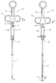
図2は本発明の第1の実施例の内視鏡用処置具の全体構成を示しており、左側は先端処置部材2が可撓性チューブ1の先端内に引き込まれた状態を示し、右側は可撓性チューブ1の先端から先端処置部材2が突出した状態を示している。
Embodiments of the present invention will be described below with reference to the drawings.
FIG. 2 shows the overall configuration of the endoscope treatment tool according to the first embodiment of the present invention. The left side shows a state in which the
1は、例えば四フッ化エチレン樹脂チューブ等からなる電気絶縁性の可撓性チューブであり、図示されていない内視鏡の処置具挿通チャンネル内に挿脱される。可撓性チューブ1の直径は、例えば2mm程度であり、長さは例えば1.5〜2m程度である。
2は、可撓性チューブ1の先端から突没する先端処置部材であり、この実施例の先端処置部材2は、高周波電流が通電されて粘膜の切開等に使用されるフック状に形成された導電性の高周波電極である。ただし、先端処置部材2がそれ以外の形状等であっても差し支えない。
可撓性チューブ1内には、例えばステンレス鋼撚り線等からなる導電性の操作ワイヤ3が軸線方向に進退自在に且つ軸線周り方向に回転自在に挿通配置され、その操作ワイヤ3の先端に先端処置部材2が連結されている。
In the
したがって、操作ワイヤ3が可撓性チューブ1内で軸線方向に進退すると、先端処置部材2が可撓性チューブ1の先端から突没し、操作ワイヤ3が可撓性チューブ1内で軸線周り方向に回転すると、先端処置部材2が可撓性チューブ1の先端部分で軸線周り方向に回転する。
Therefore, when the
可撓性チューブ1の基端には、操作ワイヤ3を可撓性チューブ1に対して進退及び回転させる操作をするための操作部10が連結されている。可撓性チューブ1の基端部分と同方向に細長く形成された操作部本体11には、スライド操作部材12がスライド操作自在に(ただし、操作部本体11に対して回転しないように)取り付けられている。
An
スライド操作部材12には操作ワイヤ3の基端が連結固定されている。したがって、矢印A、Bで示されるようにスライド操作部材12をスライド操作することにより、可撓性チューブ1内で操作ワイヤ3が進退動作をして、矢印C、Dで示されるように先端処置部材2が可撓性チューブ1の先端から突没する。
The base end of the
また、スライド操作部材12に配置された接続端子13に図示されていない高周波電源コードを接続することにより、操作ワイヤ3を経由して先端処置部材2に高周波電流を通電することができる。
In addition, by connecting a high-frequency power cord (not shown) to the
スライド操作部材12は、操作部本体11の長手方向に細長く形成されたスリット14に沿う範囲のみでスライドすることができ、スリット14の先端壁14aに当接するとそれ以上前方(図2において下方)に移動できなくなる。
The
したがって、可撓性チューブ1の先端から先端処置部材2が所定長さ以上に突出し過ぎるのを規制するための先端突出ストッパが、スリット14の先端壁14aで形成されている。ただし、先端突出ストッパがスリット14の先端壁14a以外の操作部10に設けられた部材で形成されていてもよい。
Therefore, a tip protrusion stopper for restricting the
操作部10の最先端部分には、可撓性チューブ1の基端に連結固着された回転環15が軸線周り方向に回転自在に係合している。したがって、矢印Eで示されるように、回転環15に対して操作部本体11とスライド操作部材12を一体に軸線周り方向に回転させることにより、可撓性チューブ1内で操作ワイヤ3が回転して、矢印Fで示されるように、可撓性チューブ1の先端位置にある先端処置部材2に軸線周り方向の回転力が付与される。
A rotating
図1は、内視鏡用処置具の先端部分を示しており、左側は先端処置部材2が可撓性チューブ1の先端内に引き込まれた状態を示し、右側は可撓性チューブ1の先端から先端処置部材2が突出した状態を示している。
FIG. 1 shows the distal end portion of the endoscope treatment tool, the left side shows a state where the
先端処置部材2と操作ワイヤ3とは、図3に分解して図示されているように、円筒パイプ状の導電性を有する金属製の摺接部材4を介して連結されている。具体的には、先端処置部材2の尾部に突出形成された後端突出部2aと操作ワイヤ3の先端部分とが、摺接部材4に前後から差し込まれてロー付け等によりそれらが一体に連結固定されている。
The
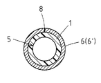
図1に戻って、可撓性チューブ1の先端近傍には内方に突出する括れ部5が形成されてその部分だけ内径が小さくなっていて、その括れ部5の内径が広がらないように括れ部5を可撓性チューブ1の外周側から締め付ける例えばステンレス鋼等のような剛性のある材料からなる締付輪6が、可撓性チューブ1に固定的に取り付けられている。締付輪6は、可撓性チューブ1の外周より外側に出っ張らないように、可撓性チューブ1の外周面から潜った状態に取り付けられている。
Returning to FIG. 1, a
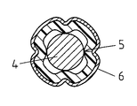
そのような括れ部5は、例えば図4に示されるように、まず可撓性チューブ1の外周にC字状の断面形状の金属輪6′を被せて、加熱しながら可撓性チューブ1の外周部において金属輪6′を縮径させる。可撓性チューブ1は金属輪6′に押されて次第に括れた状態に熱成形される。
For example, as shown in FIG. 4, such a
次いで、図5に示されるように、金属輪6′のC字状の切れ目に隙間がない状態になったら、その切れ目をレーザ溶接等で溶接することにより、一つながりの環状の締付輪6が形成される。8が溶接部である。このようにして形成された括れ部5は、内径が広がることなくその形状が長期にわたって保持される。
Next, as shown in FIG. 5, when there is no gap between the C-shaped cuts of the metal ring 6 ', the cuts are welded by laser welding or the like, so that a continuous
図1に示されるように、締付輪6の外周面を覆うように熱収縮チューブ等からなる電気絶縁性の締付輪被覆環7が被覆されていて、高周波処置が行われる際に金属製の締付輪6が周囲の生体粘膜等に触れないようになっている。締付輪被覆環7は、可撓性チューブ1の外周より外側に出っ張らないように、可撓性チューブ1の外周面から潜った状態に取り付けられている。
As shown in FIG. 1, an electrically insulating fastening
なお、締付輪被覆環7が締付輪6をくまなく覆うように、締付輪6の幅より締付輪被覆環7の幅の方が大きく形成されているが、図6に示されるように、締付輪被覆環7を締付輪6と同幅に形成すれば低コストで簡単に製造することができるメリットがある。これは、後述する各実施例においても同様である。
Note that the width of the tightening
再び図1に戻って、操作ワイヤ3と先端処置部材2との連結部に設けられた摺接部材4は、括れ部5の内面に摺接してその摺接部に摩擦抵抗が生じるようになっている。そしてその摩擦抵抗が、可撓性チューブ1に対する操作ワイヤ3と先端処置部材2の回転動作に対して付与され、また可撓性チューブ1に対する操作ワイヤ3と先端処置部材2の進退動作に対しても付与される。
Returning to FIG. 1 again, the
摺接部材4の前後両端の外縁部には丸みが形成されている。したがって、摺接部材4が軸線方向に進退して括れ部5内に出入りする場合に、摺接部材4が括れ部5に引っかかることなくスムーズに進退する。
Roundness is formed at the outer edge portions of the front and rear ends of the sliding
このように構成された実施例の内視鏡用処置具は、図1の左側部分に図示されるように、操作ワイヤ3が操作部10側から牽引されて先端処置部材2が可撓性チューブ1内に最大限引き込まれた状態のときには、摺接部材4の最先端部付近だけが括れ部5内に頭を突っ込んだ状態に摺接している。
In the endoscope treatment tool of the embodiment configured as described above, as shown in the left part of FIG. 1, the
したがって、括れ部5と摺接部材4との摺接部において僅かな摩擦抵抗が生じているだけなので、操作部10側で操作ワイヤ3が可撓性チューブ1に対し軸線周りに回転操作されると、多少の抵抗を伴いながら可撓性チューブ1の先端内で摺接部材4と先端処置部材2が軸線周りに回転して、先端処置部材2の向きを任意に調整することができる。
Accordingly, since only a slight frictional resistance is generated at the sliding contact portion between the
そして、図1の右側部分に図示されるように、操作部10側から操作ワイヤ3が最大限押し込み操作されると、先端処置部材2が可撓性チューブ1の先端から前方に予め設定された所定の長さだけ突出して、粘膜切開等を行うことができる状態になる。
1, when the
この時、摺接部材4は括れ部5の全範囲に摺接して、その摺接部に摩擦抵抗が発生している。したがって、先端処置部材2が粘膜面に軽く触れたり、操作部10側で回転環15に軽く手が触れたりしただけでは、摺接部材4が括れ部5に対して回転しない。
At this time, the
その結果、先端処置部材2が可撓性チューブ1の先端で一定の向きを保持することができて、粘膜切開処置等を正確に行うことができる。そして、締付輪6により括れ部5の断面形状がよく保持されるので、先端処置部材2の回転動作に摩擦抵抗を付与する機能が低下することなく長期にわたって維持される。
As a result, the
なお、図7に示されるように、操作部10側から操作ワイヤ3が最大限押し込み操作された時に、摺接部材4が括れ部5の前方に抜け出した状態になるようにセットしても差し支えない。
In addition, as shown in FIG. 7, the sliding
この状態では、操作ワイヤ3が操作部10側から軸線周り方向に回転操作されると、先端処置部材2がそれに追従して無抵抗に回転するので、先端処置部材2の向きを変える操作が容易である。
In this state, when the
このように構成した場合に、切開処置等を行う際には、操作ワイヤ3を少し操作部10側に引き戻して、図1の右側部分に図示されているように摺接部材4が括れ部5内に係合する状態にすればよい。なお、その状態を弾力的に保持するためのクリック機構等を操作部10側に設ければ、より使い易くなる。これは、他の実施例においても同様である。
In this configuration, when performing an incision treatment or the like, the
図8と図9は、本発明の第2と第3の実施例の内視鏡用処置具の先端部分を示しており、各図において、左側は先端処置部材2が可撓性チューブ1の先端内に引き込まれた状態を示し、右側は可撓性チューブ1の先端から先端処置部材2が突出した状態を示している。
8 and 9 show the distal end portions of the endoscope treatment tools according to the second and third embodiments of the present invention. In each figure, the
図8に示される第2の実施例では、摺接部材4が、その中央付近の中間突出部分4aのみにおいて括れ部5と摺接するように、局部的に丸まった大きな外径に形成され、図9に示される第3の実施例では、摺接部材4の外径が前後両端から中間部分へ次第に大きく形成されている。
In the second embodiment shown in FIG. 8, the sliding
このように摺接部材4の中間部分の外径が前後両端付近より膨らんで大きく形成されていると、摺接部材4が、軸線方向に移動する際に括れ部5に対してスムーズに係合することができる。
Thus, when the outer diameter of the intermediate portion of the sliding
図10は、本発明の第4の実施例における括れ部5部分の断面図(軸線に対して垂直な断面図)であり、締付輪被覆環7の図示は省略されている。以下の実施例でも同様である。
FIG. 10 is a cross-sectional view (cross-sectional view perpendicular to the axis) of the
前述の第1〜第3の各実施例においては、摺接部材4の外面と括れ部5の内面の断面形状が共に円形であったが、この実施例では、摺接部材4の外面の断面形状が正方形状に形成されている。ただし、その角部は滑らかに丸められている。
In each of the first to third embodiments described above, the cross-sectional shapes of the outer surface of the sliding
このように、括れ部5の内面の断面形状が円形の場合に、摺接部材4の外面の断面形状を非円形にすることにより、摺接面が部分的な狭い範囲になるので、寸法誤差等に対する摩擦抵抗の大きさの変化が小さくなって、摩擦抵抗の設定や調整等が容易になる。
As described above, when the cross-sectional shape of the inner surface of the
図11及び図12は本発明の第5及び第6の実施例であり、図11に示される第5の実施例では、締付輪6の内面形状が例えば四つの凹凸が繰り返される波形の形状に形成され、図12に示される第6の実施例では、締付輪6の内面形状が正八角形に形成されている。
FIGS. 11 and 12 show fifth and sixth embodiments of the present invention. In the fifth embodiment shown in FIG. 11, the inner shape of the
このように、摺接部材4の外面の断面形状が円形の場合に、括れ部5の内面の断面形状を非円形にして、締付輪6の断面形状も括れ部5内面に対応する非円形の断面形状に形成することにより、やはり摺接面が部分的な狭い範囲になるので、寸法誤差に対する摩擦抵抗の大きさの変化が小さくなって、摩擦抵抗の設定や調整等が容易になる。
Thus, when the cross-sectional shape of the outer surface of the sliding
なお、本発明は上記各実施例に限定されるものではなく、例えば、先端処置部材2と操作ワイヤ3とを連結するパイプ状部材を摺接部材4とは別部品として導電性金属材で形成し、それらを接着剤等で一体的に固着した構成を採ってもよい。そのようにすることで、先端処置部材2と操作ワイヤ3とを連結固着するためのロー等が摺接部材4の表面に流れ出さず、また、摺接部材4の材質や形状等の自由性が増すメリットがある。また、先端処置部材2に高周波電流が通電されない機械的な内視鏡用処置具等に本発明を適用してもよい。
The present invention is not limited to the above-described embodiments. For example, a pipe-shaped member that connects the
1 可撓性チューブ
2 先端処置部材
3 操作ワイヤ
4 摺接部材
5 括れ部
6 締付輪
7 締付輪被覆環
10 操作部
14 スリット
14a 先端壁(先端突出ストッパ)
15 回転環
DESCRIPTION OF
15 Rotating ring
Claims (16)
上記可撓性チューブの先端近傍に内方に突出する括れ部が形成されて、その括れ部の内径が広がらないように上記括れ部を上記可撓性チューブの外周側から締め付ける剛性のある材料からなる締付輪が上記可撓性チューブに固定的に取り付けられ、
上記括れ部の内面に摺接することにより上記可撓性チューブに対する上記操作ワイヤと上記先端処置部材の回転動作に摩擦抵抗を付与する摺接部材が、上記操作ワイヤと上記先端処置部材との連結部付近に設けられていることを特徴とする内視鏡用処置具。 The distal end of the flexible tube protrudes and retracts from the distal end of the flexible tube by the forward and backward movement of the operational wire at the distal end of the operational wire that is inserted in the flexible tube so as to be movable forward and backward in the axial direction and rotatable in the direction around the axial line. In an endoscopic treatment tool to which a distal treatment member that rotates in the direction around the axis of the flexible tube is connected by a rotation operation of an operation wire,
A constricted portion projecting inward is formed in the vicinity of the distal end of the flexible tube, and the constricted portion is made of a rigid material that tightens the constricted portion from the outer peripheral side of the flexible tube so that the inner diameter of the constricted portion does not widen. A fastening ring is fixedly attached to the flexible tube,
A sliding contact member that applies frictional resistance to the rotational movement of the manipulation wire and the distal treatment member relative to the flexible tube by slidingly contacting the inner surface of the constricted portion is a connecting portion between the manipulation wire and the distal treatment member. An endoscopic treatment tool characterized by being provided in the vicinity.
Priority Applications (1)
| Application Number | Priority Date | Filing Date | Title |
|---|---|---|---|
| JP2008199125A JP5114333B2 (en) | 2008-08-01 | 2008-08-01 | Endoscopic treatment tool |
Applications Claiming Priority (1)
| Application Number | Priority Date | Filing Date | Title |
|---|---|---|---|
| JP2008199125A JP5114333B2 (en) | 2008-08-01 | 2008-08-01 | Endoscopic treatment tool |
Publications (2)
| Publication Number | Publication Date |
|---|---|
| JP2010035668A true JP2010035668A (en) | 2010-02-18 |
| JP5114333B2 JP5114333B2 (en) | 2013-01-09 |
Family
ID=42008830
Family Applications (1)
| Application Number | Title | Priority Date | Filing Date |
|---|---|---|---|
| JP2008199125A Active JP5114333B2 (en) | 2008-08-01 | 2008-08-01 | Endoscopic treatment tool |
Country Status (1)
| Country | Link |
|---|---|
| JP (1) | JP5114333B2 (en) |
Cited By (4)
| Publication number | Priority date | Publication date | Assignee | Title |
|---|---|---|---|---|
| WO2011104960A1 (en) * | 2010-02-26 | 2011-09-01 | オリンパスメディカルシステムズ株式会社 | Endoscope apparatus |
| JP2016140630A (en) * | 2015-02-03 | 2016-08-08 | 日本ゼオン株式会社 | Treatment instrument for endoscope |
| JP2017123995A (en) * | 2016-01-13 | 2017-07-20 | Hoya株式会社 | High-frequency treatment instrument for endoscope |
| JP2017205211A (en) * | 2016-05-17 | 2017-11-24 | 株式会社カネカ | Medical treatment instrument |
Families Citing this family (1)
| Publication number | Priority date | Publication date | Assignee | Title |
|---|---|---|---|---|
| KR101967362B1 (en) * | 2017-09-18 | 2019-04-12 | 원텍 주식회사 | Optical delivery catheter |
Citations (5)
| Publication number | Priority date | Publication date | Assignee | Title |
|---|---|---|---|---|
| JP2004097624A (en) * | 2002-09-11 | 2004-04-02 | Olympus Corp | Expansion type griping forceps |
| JP2005270240A (en) * | 2004-03-24 | 2005-10-06 | Pentax Corp | Projecting/retracting treatment implement for endoscope |
| JP2007215786A (en) * | 2006-02-17 | 2007-08-30 | Pentax Corp | High-frequency knife for endoscope |
| JP2007229102A (en) * | 2006-02-28 | 2007-09-13 | Pentax Corp | High frequency treating implement for endoscope |
| JP2007319424A (en) * | 2006-06-01 | 2007-12-13 | Pentax Corp | Endoscopic treatment tool |
-
2008
- 2008-08-01 JP JP2008199125A patent/JP5114333B2/en active Active
Patent Citations (5)
| Publication number | Priority date | Publication date | Assignee | Title |
|---|---|---|---|---|
| JP2004097624A (en) * | 2002-09-11 | 2004-04-02 | Olympus Corp | Expansion type griping forceps |
| JP2005270240A (en) * | 2004-03-24 | 2005-10-06 | Pentax Corp | Projecting/retracting treatment implement for endoscope |
| JP2007215786A (en) * | 2006-02-17 | 2007-08-30 | Pentax Corp | High-frequency knife for endoscope |
| JP2007229102A (en) * | 2006-02-28 | 2007-09-13 | Pentax Corp | High frequency treating implement for endoscope |
| JP2007319424A (en) * | 2006-06-01 | 2007-12-13 | Pentax Corp | Endoscopic treatment tool |
Cited By (5)
| Publication number | Priority date | Publication date | Assignee | Title |
|---|---|---|---|---|
| WO2011104960A1 (en) * | 2010-02-26 | 2011-09-01 | オリンパスメディカルシステムズ株式会社 | Endoscope apparatus |
| CN102413755A (en) * | 2010-02-26 | 2012-04-11 | 奥林巴斯医疗株式会社 | Endoscope apparatus |
| JP2016140630A (en) * | 2015-02-03 | 2016-08-08 | 日本ゼオン株式会社 | Treatment instrument for endoscope |
| JP2017123995A (en) * | 2016-01-13 | 2017-07-20 | Hoya株式会社 | High-frequency treatment instrument for endoscope |
| JP2017205211A (en) * | 2016-05-17 | 2017-11-24 | 株式会社カネカ | Medical treatment instrument |
Also Published As
| Publication number | Publication date |
|---|---|
| JP5114333B2 (en) | 2013-01-09 |
Similar Documents
| Publication | Publication Date | Title |
|---|---|---|
| JP4441496B2 (en) | Bipolar high-frequency treatment instrument for endoscope | |
| JP4731274B2 (en) | Endoscopic high-frequency incision tool | |
| JP5114333B2 (en) | Endoscopic treatment tool | |
| JP4598197B2 (en) | Endoscopic treatment tool | |
| JP2009034388A (en) | Operation section structure of treatment instrument for endoscopic use | |
| JP4425224B2 (en) | High frequency knife for endoscope | |
| JP4425223B2 (en) | High frequency knife for endoscope | |
| JP4441492B2 (en) | High frequency knife for endoscope | |
| JP5601776B2 (en) | Endoscopic high-frequency treatment instrument | |
| JP2007111149A (en) | High frequency incising instrument for endoscope | |
| JP5355054B2 (en) | Endoscopic treatment tool | |
| JP5288953B2 (en) | Endoscopic treatment tool | |
| JP2005270240A (en) | Projecting/retracting treatment implement for endoscope | |
| JP4996440B2 (en) | Endoscopic high-frequency treatment instrument | |
| JP5191338B2 (en) | Bipolar high-frequency snare for endoscope | |
| JP4503038B2 (en) | Endoscopic treatment tool | |
| JP2008253352A (en) | Treatment tool for endoscope | |
| JP2007319424A (en) | Endoscopic treatment tool | |
| JP5137754B2 (en) | Endoscopic treatment tool | |
| JP2008043716A (en) | Clip unit for endoscope | |
| JP2006314570A (en) | Variable injection needle | |
| JP2012050758A (en) | Hook-like high-frequency knife for flexible endoscope | |
| JP2010188116A (en) | Treatment instrument for endoscope | |
| JP2009207707A (en) | Treatment tool for endoscope | |
| JP5191365B2 (en) | Endoscopic high-frequency treatment instrument |
Legal Events
| Date | Code | Title | Description |
|---|---|---|---|
| A621 | Written request for application examination |
Free format text: JAPANESE INTERMEDIATE CODE: A621 Effective date: 20110413 |
|
| RD02 | Notification of acceptance of power of attorney |
Free format text: JAPANESE INTERMEDIATE CODE: A7422 Effective date: 20120719 |
|
| RD04 | Notification of resignation of power of attorney |
Free format text: JAPANESE INTERMEDIATE CODE: A7424 Effective date: 20120727 |
|
| TRDD | Decision of grant or rejection written | ||
| A01 | Written decision to grant a patent or to grant a registration (utility model) |
Free format text: JAPANESE INTERMEDIATE CODE: A01 Effective date: 20121005 |
|
| A01 | Written decision to grant a patent or to grant a registration (utility model) |
Free format text: JAPANESE INTERMEDIATE CODE: A01 |
|
| A61 | First payment of annual fees (during grant procedure) |
Free format text: JAPANESE INTERMEDIATE CODE: A61 Effective date: 20121015 |
|
| FPAY | Renewal fee payment (event date is renewal date of database) |
Free format text: PAYMENT UNTIL: 20151019 Year of fee payment: 3 |
|
| R150 | Certificate of patent or registration of utility model |
Ref document number: 5114333 Country of ref document: JP Free format text: JAPANESE INTERMEDIATE CODE: R150 Free format text: JAPANESE INTERMEDIATE CODE: R150 |
|
| S531 | Written request for registration of change of domicile |
Free format text: JAPANESE INTERMEDIATE CODE: R313531 |
|
| R350 | Written notification of registration of transfer |
Free format text: JAPANESE INTERMEDIATE CODE: R350 |
|
| R250 | Receipt of annual fees |
Free format text: JAPANESE INTERMEDIATE CODE: R250 |
|
| R250 | Receipt of annual fees |
Free format text: JAPANESE INTERMEDIATE CODE: R250 |
|
| R250 | Receipt of annual fees |
Free format text: JAPANESE INTERMEDIATE CODE: R250 |
|
| R250 | Receipt of annual fees |
Free format text: JAPANESE INTERMEDIATE CODE: R250 |
|
| R250 | Receipt of annual fees |
Free format text: JAPANESE INTERMEDIATE CODE: R250 |
|
| R250 | Receipt of annual fees |
Free format text: JAPANESE INTERMEDIATE CODE: R250 |
|
| R250 | Receipt of annual fees |
Free format text: JAPANESE INTERMEDIATE CODE: R250 |
|
| R250 | Receipt of annual fees |
Free format text: JAPANESE INTERMEDIATE CODE: R250 |