JP2010035384A - Portable information terminal - Google Patents
Portable information terminal Download PDFInfo
- Publication number
- JP2010035384A JP2010035384A JP2008197477A JP2008197477A JP2010035384A JP 2010035384 A JP2010035384 A JP 2010035384A JP 2008197477 A JP2008197477 A JP 2008197477A JP 2008197477 A JP2008197477 A JP 2008197477A JP 2010035384 A JP2010035384 A JP 2010035384A
- Authority
- JP
- Japan
- Prior art keywords
- charger
- vehicle
- portable information
- charging
- information terminal
- Prior art date
- Legal status (The legal status is an assumption and is not a legal conclusion. Google has not performed a legal analysis and makes no representation as to the accuracy of the status listed.)
- Granted
Links
Images


Classifications
-
- Y—GENERAL TAGGING OF NEW TECHNOLOGICAL DEVELOPMENTS; GENERAL TAGGING OF CROSS-SECTIONAL TECHNOLOGIES SPANNING OVER SEVERAL SECTIONS OF THE IPC; TECHNICAL SUBJECTS COVERED BY FORMER USPC CROSS-REFERENCE ART COLLECTIONS [XRACs] AND DIGESTS
- Y02—TECHNOLOGIES OR APPLICATIONS FOR MITIGATION OR ADAPTATION AGAINST CLIMATE CHANGE
- Y02E—REDUCTION OF GREENHOUSE GAS [GHG] EMISSIONS, RELATED TO ENERGY GENERATION, TRANSMISSION OR DISTRIBUTION
- Y02E60/00—Enabling technologies; Technologies with a potential or indirect contribution to GHG emissions mitigation
- Y02E60/10—Energy storage using batteries
Abstract
Description
本発明は、携帯情報端末に関するものである。 The present invention relates to a portable information terminal.
バーコードリーダなどの光学的情報読取装置や決済端末などでは、充電可能な電池を内蔵した携帯型の情報端末が提供されている。この種の携帯情報端末は、様々な場所に持ち運んで使用できるという利点を有するが、不使用時には充電器によって電池を充電する必要があり、現在では、このような充電器として様々なタイプのものが提供されている。なお、携帯情報端末の充電に関する技術(特に、充電器に関する技術)としては、例えば特許文献1,2のようなものが提供されている。
ところで、上記のような携帯情報端末はその使われ方も様々であり、使用場所や用途も様々であるため、充電場所も一律ではない場合が多い。例えば、充電がオフィスや工場といった屋内で行われることもあるし、車両等の車内で行われることもあるが、このように充電場所が異なると、充電環境が大きく変わりうるという問題があった。例えば、一般室内と比較して車両内のほうが高温となりやすいという問題があるが、従来では、このような充電環境に関係なく一律に充電制御を行っており、必ずしも充電環境に適した制御であるとは言えなかった。 By the way, since the above-mentioned portable information terminals are used in various ways and used in various places and uses, there are many cases where the charging places are not uniform. For example, charging may be performed indoors, such as in an office or a factory, or in a vehicle such as a vehicle. However, there is a problem that the charging environment can vary greatly if the charging location is different. For example, there is a problem that the temperature inside a vehicle is likely to be higher than that in a general room, but conventionally, charging control is uniformly performed regardless of such a charging environment, and the control is not necessarily suitable for the charging environment. I couldn't say that.
本発明は、上述した課題を解決するためになされたものであり、充電環境に適した適切な充電制御を行うことのできる携帯情報端末を提供することを目的とする。 The present invention has been made to solve the above-described problems, and an object thereof is to provide a portable information terminal capable of performing appropriate charging control suitable for a charging environment.
上記目的を達成するため、請求項1の発明は、充電可能な電池を装置本体内に収容してなる携帯情報端末であって、前記装置本体に設けられ、構成及び用途の異なる複数種類の充電器が接続可能に構成された接続手段と、前記接続手段と前記充電器との接続を検出する接続検出手段と、各種類の前記充電器の構成に基づき、前記接続検出手段により接続が検出された前記充電器の用途を判別する判別手段と、前記電池の充電制御を行う充電制御手段と、を備え、前記充電制御手段は、前記充電器の用途毎に充電制御方式が定められており、前記接続検出手段により前記充電器の接続が検出されたとき、前記判別手段によって判別された前記充電器の用途に対応した方式で前記電池の充電制御を行うことを特徴とする。
In order to achieve the above object, the invention of
請求項2の発明は、請求項1に記載の携帯情報端末において、前記接続手段は、所定構成の室内用充電器と、当該室内用充電器とは構成の異なる車載用充電器と、が接続可能とされ、前記充電制御手段は、前記室内用充電器に対応して室内用の充電方式が定められ、前記車載用充電器に対応して車載用の充電方式が定められており、前記判別手段によって前記室内用充電器と判別された場合には前記室内用の充電方式で前記電池の充電制御を行い、前記車載用充電器と判別された場合には前記車載用の充電方式で前記電池の充電制御を行うことを特徴とする。 According to a second aspect of the present invention, in the portable information terminal according to the first aspect, the connection means connects an indoor charger having a predetermined configuration and an in-vehicle charger having a different configuration from the indoor charger. The charging control means is configured to determine a room charging method corresponding to the indoor charger, and to determine a vehicle charging method corresponding to the vehicle charger. If the battery charger is determined to be the indoor charger, the battery charging control is performed using the indoor charging method. If the battery charger is determined to be the vehicle charger, the battery is charged using the vehicle charging method. The charge control is performed.
請求項3の発明は、請求項2に記載の携帯情報端末において、前記充電制御手段は、前記車載用充電器が前記接続手段に接続されているときに前記電池に供給する充電電流を、前記室内用充電器が前記接続手段に接続されているときに前記電池に供給する前記充電電流よりも電流量を少なくすることを特徴とする。 According to a third aspect of the present invention, in the portable information terminal according to the second aspect, the charging control means supplies a charging current supplied to the battery when the in-vehicle charger is connected to the connecting means, A current amount is made smaller than the charging current supplied to the battery when an indoor charger is connected to the connecting means.
請求項4の発明は、請求項2又は請求項3に記載の携帯情報端末において、前記電池の温度を検出する温度検出手段を備え、前記充電制御手段は、前記温度検出手段によって検出される前記電池の温度が閾値を超えた場合に、前記電池の充電を遮断又は抑制する構成をなしており、更に、充電制御手段は、前記室内用充電器が前記接続手段に接続されているときに前記閾値を第1の値に設定し、前記車載用充電器が前記接続手段に接続されているときに前記閾値を前記第1の値よりも低い第2の値に設定する制御を行うことを特徴とする。 According to a fourth aspect of the present invention, in the portable information terminal according to the second or third aspect, the portable information terminal includes a temperature detection unit that detects a temperature of the battery, and the charge control unit is detected by the temperature detection unit. When the temperature of the battery exceeds a threshold value, it is configured to cut off or suppress the charging of the battery, and further, the charging control means is configured so that the indoor charger is connected to the connecting means. The threshold value is set to a first value, and control is performed to set the threshold value to a second value lower than the first value when the on-vehicle charger is connected to the connection means. And
請求項5の発明は、請求項2から請求項4のいずれか一項に記載の携帯情報端末において、前記判別手段は、前記車載用充電器に複数形成され且つ前記室内用充電器に形成されていない車載用特徴部を検知する特徴検知部を複数備え、それら複数の前記特徴検知部の全てで前記車載用特徴部が検知された場合に前記車載用充電器が接続されていると判断することを特徴とする。 According to a fifth aspect of the present invention, in the portable information terminal according to any one of the second to fourth aspects, a plurality of the determination means are formed in the on-vehicle charger and are formed in the indoor charger. A plurality of feature detection units for detecting a non-vehicle feature, and when the vehicle feature is detected by all of the plurality of feature detection units, it is determined that the vehicle charger is connected It is characterized by that.
請求項6の発明は、請求項2から請求項5のいずれか一項に記載の携帯情報端末において、前記接続手段は、前記車載用充電器に形成され且つ前記室内用充電器に形成されていない嵌合部と嵌合する被嵌合部を備え、前記装置本体は、前記車載用充電器に保持される際に、前記嵌合部と前記被嵌合部とが嵌合して前記車載用充電器に組み付けられる構成をなしており、前記判別手段は、前記嵌合部と前記被嵌合部との嵌合を検知する嵌合検知部を備え、前記嵌合検知部により前記被係合部と前記係合部との嵌合が検知された場合に前記車載用充電器が接続されていると判断することを特徴とする。 According to a sixth aspect of the present invention, in the portable information terminal according to any one of the second to fifth aspects, the connecting means is formed in the in-vehicle charger and formed in the indoor charger. A fitting portion that fits with a fitting portion that does not fit, and when the apparatus main body is held by the on-vehicle charger, the fitting portion and the fitted portion are fitted to each other and the on-vehicle portion The determination unit includes a fitting detection unit that detects the fitting between the fitting unit and the mated unit, and the mating detection unit detects the engagement. It is determined that the in-vehicle charger is connected when a fitting between the joint portion and the engaging portion is detected.
請求項7の発明は、請求項6に記載の携帯情報端末において、前記接続手段は、前記装置本体が前記車載用充電器に装着される際に前記嵌合部を前記被嵌合部側に案内するガイド溝を備え、前記ガイド溝内において前記被嵌合部が形成されていることを特徴とする。 According to a seventh aspect of the present invention, in the portable information terminal according to the sixth aspect, the connection means moves the fitting portion to the fitted portion side when the device main body is attached to the in-vehicle charger. A guide groove for guiding is provided, and the fitted portion is formed in the guide groove.
請求項8の発明は、請求項7に記載の携帯情報端末において、前記ガイド溝は、前記室内用充電器に形成されたガイドリブのガイドに兼用される構成をなしており、前記被嵌合部は、前記ガイド溝の溝底よりも更に奥まった位置に凹状に形成されていることを特徴とする。 An eighth aspect of the present invention is the portable information terminal according to the seventh aspect, wherein the guide groove is also used as a guide of a guide rib formed in the indoor charger, and the fitted portion Is characterized by being formed in a concave shape at a position deeper than the groove bottom of the guide groove.
請求項9の発明は、請求項6から請求項8のいずれか一項に記載の携帯情報端末において、前記車載用充電器は、前記接続手段との接続時に第1状態となる第1識別端子を備えるものであり、前記室内用充電器は、前記接続手段との接続時に前記第1状態とは異なる第2状態となる第2識別端子を備えるものであり、前記接続手段は、前記車載用充電器の接続時に前記第1識別端子と接続し、前記室内用充電器の接続時に前記第2識別端子と接続する接続端子を備え、前記判別手段は、前記嵌合検知部による前記嵌合部と前記被嵌合部との嵌合の検知結果、及び前記接続端子の状態に基づいて、前記接続手段に接続される前記充電器の用途判別、及びその接続される前記充電器の異常状態の判別を行うことを特徴とする。 A ninth aspect of the present invention is the portable information terminal according to any one of the sixth to eighth aspects, wherein the on-vehicle charger is in a first state when connected to the connection means. The indoor charger is provided with a second identification terminal that is in a second state different from the first state when connected to the connection means, and the connection means is provided for the in-vehicle use. A connection terminal connected to the first identification terminal when the charger is connected and connected to the second identification terminal when the indoor charger is connected; and the determination means includes the fitting portion by the fitting detection portion. Based on the detection result of the fitting with the fitting portion and the state of the connection terminal, the use determination of the charger connected to the connection means, and the abnormal state of the connected charger It is characterized by performing discrimination.
請求項1の発明では、充電器の用途毎に充電制御方式が定められており、接続が検出された充電器の用途に対応した方式で電池の充電制御を行っている。このようにすると、充電器の用途毎に充電制御方式を変更でき、各用途に適した充電制御を行うことができるようになる。従って、全ての充電器種別に対して同一の充電制御方式を用いる構成と比較して、より適切で効率的な充電制御が可能となる。 In the first aspect of the present invention, a charging control method is determined for each application of the charger, and charging control of the battery is performed by a method corresponding to the application of the charger in which connection is detected. If it does in this way, a charge control system can be changed for every use of a charger, and it will become possible to perform charge control suitable for each use. Therefore, more appropriate and efficient charge control is possible compared to a configuration using the same charge control method for all charger types.
請求項2の発明では、所定構成の室内用充電器と、当該室内用充電器とは構成の異なる車載用充電器と、が接続可能とされると共に、室内用充電器に対応して室内用の充電方式が定められ、車載用充電器に対応して車載用の充電方式が定められている。このようにすると、充電場所が室内であるか車内であるかを適切に判断できると共に、環境が異なる室内と車内とで充電方式を変えることができる。そして、室内においては室内に適した充電制御を行うことができ、車内においては車内に適した充電制御を行うことができるようになる。 According to the second aspect of the present invention, an indoor charger having a predetermined configuration and an in-vehicle charger having a different configuration from the indoor charger can be connected, and the indoor charger corresponding to the indoor charger is used. The in-vehicle charging method is determined corresponding to the in-vehicle charger. In this way, it is possible to appropriately determine whether the charging place is in the room or in the vehicle, and it is possible to change the charging method between the room and the vehicle in different environments. In addition, the charging control suitable for the room can be performed indoors, and the charging control suitable for the interior can be performed inside the car.
請求項3の発明では、車載用充電器が接続手段に接続されているときに電池に供給する充電電流を、室内用充電器が接続手段に接続されているときに電池に供給する充電電流よりも電流量を少なくしている。車載用充電器が接続されている場合(即ち、車内で充電される場合)、室内で充電される場合と比較して携帯情報端末の周囲温度が高くなりやすいが、本発明のように車載用充電器の接続時に充電量を少なくする制御を行うようにすれば、高温となりやすい車両内において電池や周囲部品、或いは充電器の温度上昇を抑えることができ、高温化に伴う不具合を効果的に抑制できる。
According to the invention of
請求項4の発明では、電池の温度を検出する温度検出手段を備えており、この温度検出手段によって検出される電池の温度が閾値を超えた場合、充電制御手段によって電池の充電を遮断又は抑制している。このようにすると、電池の過熱を適切に検出でき、電池を効果的に保護できる。更に、室内用充電器が接続手段に接続されているときに閾値を第1の値に設定し、車載用充電器が接続手段に接続されているときに閾値を第1の値よりも低い第2の値に設定する制御を行うようにしている。このようにすると、室内で充電を行う際の過熱保護の水準を適切なレベルに定めることができ、高温になりやすい車両内での充電については、室内よりも過熱保護の水準を引き上げて電池や周囲部品、或いは充電器を効果的に保護できるようになる。 According to a fourth aspect of the present invention, there is provided temperature detecting means for detecting the temperature of the battery, and when the temperature of the battery detected by the temperature detecting means exceeds a threshold value, charging of the battery is interrupted or suppressed by the charge control means. is doing. If it does in this way, overheating of a battery can be detected appropriately and a battery can be protected effectively. Further, the threshold value is set to the first value when the indoor charger is connected to the connecting means, and the threshold value is lower than the first value when the in-vehicle charger is connected to the connecting means. Control to set the value to 2 is performed. In this way, the level of overheat protection when charging indoors can be set to an appropriate level. It becomes possible to effectively protect the surrounding parts or the charger.
請求項5の発明は、車載用充電器に複数形成され且つ室内用充電器に形成されていない車載用特徴部を検知する特徴検知部を複数備えており、それら複数の特徴検知部の全てで車載用特徴部が検知された場合に車載用充電器が接続されていると判断している。このように複数の車載用特徴部の全てを検出する構成とすれば、車載用充電器が接続されているか否かを精度高く判断できるようになる。 The invention according to claim 5 includes a plurality of feature detection units that detect a plurality of on-vehicle features that are formed on the on-vehicle charger and that are not formed on the indoor charger. When the in-vehicle feature is detected, it is determined that the in-vehicle charger is connected. Thus, if it is set as the structure which detects all the some vehicle-mounted characteristic parts, it will become possible to determine with high precision whether the vehicle-mounted charger is connected.
請求項6の発明は、車載用充電器に形成され且つ室内用充電器に形成されていない嵌合部と嵌合する被嵌合部を備えており、装置本体が車載用充電器に保持される際に、嵌合部と被嵌合部とが嵌合して車載用充電器に組み付けられる構成となっている。このようにすると、比較的振動を伴う車両内において携帯情報端末を充電器に安定的に組み付けることができ、車両に比べて振動のない室内においては嵌合させずに着脱の容易化を図ることができる。さらに、嵌合部と被嵌合部とを利用して車載用充電器が接続されているか否かを検出しており、このようにすれば、車載用と室内用とを判断するための特別構成を別途多く用意する必要がなく、携帯情報端末及び車載用充電器における振動に対応するための特徴構成を用いて車載用か室内用かを適切に判断できるようになる。 The invention of claim 6 includes a fitted portion that is fitted to a fitting portion that is formed in the in-vehicle charger and is not formed in the indoor charger, and the apparatus main body is held by the in-vehicle charger. In this case, the fitting portion and the fitted portion are fitted and assembled to the in-vehicle charger. In this way, the portable information terminal can be stably assembled to the charger in a vehicle with relatively vibration, and can be easily attached and detached without being fitted in a room without vibration compared to the vehicle. Can do. Further, it is detected whether or not the in-vehicle charger is connected by using the fitting portion and the fitted portion, and in this way, a special for determining whether the in-vehicle charger or the indoor charger is used. It is not necessary to prepare a large number of separate configurations, and it is possible to appropriately determine whether the vehicle is mounted or used indoors by using the characteristic configuration for dealing with vibrations in the portable information terminal and the vehicle charger.
請求項7の発明は、装置本体が車載用充電器に装着される際に嵌合部を被嵌合部側に案内するガイド溝を備えており、このガイド溝内において被嵌合部が形成されている。このようにすると携帯情報端末を車載用充電器に装着する装着操作において、装置本体が車載用充電器の適切な位置に案内されやすくなり、車載用充電器に対する装置本体の位置決め、装着操作を容易に行うことができるようになる。 The invention of claim 7 is provided with a guide groove for guiding the fitting portion to the fitted portion side when the apparatus main body is attached to the in-vehicle charger, and the fitted portion is formed in the guide groove. Has been. In this way, in the mounting operation for mounting the portable information terminal on the in-vehicle charger, the device main body is easily guided to an appropriate position of the in-vehicle charger, and the positioning and mounting operation of the device main body with respect to the in-vehicle charger is easy. To be able to do that.
請求項8の発明は、ガイド溝が室内用充電器に形成されたガイドリブのガイドに兼用される構成をなしており、被嵌合部がガイド溝の溝底よりも更に奥まった位置に凹状に形成されている。このようにすると、ガイド溝によって室内用充電器を適切な位置に位置決めすることができ、更に、そのガイド溝を、室内用充電器の位置決めと、嵌合部の案内とに兼用できるようになる。 The invention according to claim 8 is configured such that the guide groove is also used as a guide of a guide rib formed in the indoor charger, and the fitted portion is recessed at a position deeper than the groove bottom of the guide groove. Is formed. In this way, the indoor charger can be positioned at an appropriate position by the guide groove, and the guide groove can be used both for positioning the indoor charger and guiding the fitting portion. .
請求項9の発明では、嵌合検知部による嵌合の検知結果、及び接続端子の状態に基づいて、接続手段に接続される充電器の用途判別、及びその接続される充電器の異常状態の判別を行っている。このようにすると、接続される充電器の用途をより確実に判別でき、また、充電器の異常状態をも判別できるため、接続される充電器の用途及び充電器の異常状態を反映したより一層適切な充電制御を行うことができるようになる。 In the invention of claim 9, based on the detection result of the fitting by the fitting detector and the state of the connection terminal, the use determination of the charger connected to the connection means, and the abnormal state of the connected charger Discriminating. In this way, the usage of the connected charger can be more reliably determined, and the abnormal state of the charger can also be determined. Therefore, the usage of the connected charger and the abnormal state of the charger are further reflected. Appropriate charge control can be performed.
[第1実施形態]
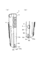
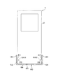
以下、本発明の携帯端末を具現化した第1実施形態について、図面を参照して説明する。図1(a)は、本発明の第1実施形態に係る携帯情報端末を概略的に示す側面図であり、図1(b)は、(a)とは反対側の側面を部分的に示す図である。図2は、図1の携帯情報端末を充電する車載用充電器の一部を概略的に示す斜視図である。図3は、携帯情報端末と車載用充電器とを概念的に示す概念図であり、図4は、携帯情報端末を車載用充電器に載置した状態を説明する説明図である。図5(a)は、携帯情報端末と室内用充電器とを概念的に示す概念図であり、図5(b)は、室内用充電器を携帯情報端末の挿入側から見た概念図である。図6は、携帯情報端末を室内用充電器に載置した状態を説明する説明図である。
[First embodiment]
Hereinafter, a first embodiment in which a portable terminal of the present invention is embodied will be described with reference to the drawings. Fig.1 (a) is a side view which shows schematically the portable information terminal which concerns on 1st Embodiment of this invention, FIG.1 (b) shows the side surface on the opposite side to (a) partially. FIG. FIG. 2 is a perspective view schematically showing a part of the in-vehicle charger for charging the portable information terminal of FIG. FIG. 3 is a conceptual diagram conceptually showing the portable information terminal and the in-vehicle charger, and FIG. 4 is an explanatory diagram for explaining a state in which the portable information terminal is placed on the in-vehicle charger. FIG. 5A is a conceptual diagram conceptually showing the portable information terminal and the indoor charger, and FIG. 5B is a conceptual diagram of the indoor charger viewed from the insertion side of the portable information terminal. is there. FIG. 6 is an explanatory diagram illustrating a state where the portable information terminal is placed on the indoor charger.
まず、図1〜図6を参照して携帯情報端末1及び充電器の形態等について説明する。
図1に示すように、携帯情報端末1は、充電可能なバッテリ3を装置本体2内に収容してなるものであり、ユーザが持ち運んで使用可能な携帯型の電子機器として構成されている。なお、携帯型の電子機器としては、例えば、バーコードリーダ、二次元コードリーダ等の光学的情報読取装置、或いはICカード等を読み取る決済端末などが挙げられ、以下では、その一例として光学的情報読取装置に適用される場合について説明する。
First, the forms of the
As shown in FIG. 1, the
図1に示すように、装置本体2は、ケース4によって外郭が構成されており、このケース4内にバッテリ3から電力供給を受ける各種電気部品やその他の部品が収容されている。また、装置本体2の内部には、バッテリ3を収容する箱状の収容部(図示略)が形成されており、この箱状の収容部が図示しない電池蓋によって閉塞された構成となっている。
As shown in FIG. 1, the apparatus
バッテリ3は、装置本体2に対して着脱可能とされており、装着時には上記収容部(図示略)に収容され、電池蓋よって閉塞されることで装置本体2内に保持されるようになっている。また、取り外し時には電池蓋を開放して収容部を露出させることでバッテリ3を外部に取り外すことができるようになっている。なお、バッテリ3は、リチウムイオン電池、ニッケル水素電池、ニッケルカドミウム電池等の公知の二次電池によって構成されており、後述する充電器(車載用充電器90や室内用充電器80など)によって充電可能とされている。
The
装置本体2の長手方向一端側には接続部50が形成されている。接続部50は、構成及び用途の異なる複数種類の充電器(本実施形態では、室内用充電器80及び車載用充電器90)に接続される部分であり、これら複数種類の充電器に保持され且つこれら複数種類の充電器と電気的に接続されるコネクタとして機能している。例えば、車載用充電器90を携帯情報端末1の充電に用いる場合には、当該車載用充電器90によって接続部50が保持され、その保持状態で接続部50と車載用充電器90とが電気的に接続されるようになっている(図4参照:後述)。また、室内用充電器80を携帯情報端末1の充電に用いる場合には、当該室内用充電器80によって接続部50が保持され、その保持状態で接続部50と室内用充電器80とが電気的に接続されるようになっている(図6参照:後述)。なお、接続部50は、「接続手段」の一例に相当している。
A
また、接続部50は、図1、図2に示すように、室内用充電器80や車載用充電器90の端子と接続する端子T1,T2、T3を備えると共に、これら室内用充電器80及び車載用充電器90と係合する係合部51、52を有している。これら係合部51、52は、装置本体2の側壁2a、2bにそれぞれ形成されたガイド溝53、54と、このガイド溝53、54内に形成された穴部55、56とによって構成されている。ガイド溝53、54は、携帯情報端末1の長手方向に沿って延びる溝形状をなしており、車載用充電器90や室内用充電器80の一部を案内する機能を有している。
1 and 2, the
このような接続部50と接続し、携帯情報端末1を充電する車載用充電器としては、例えば図2〜図4のような構成のものが挙げられる。図2〜図4に示す車載用充電器90は、装置本体2にそれぞれ形成された一対の係合部51、52と係合する一対の被係合部91、92を備えており、図4のような保持状態において、被係合部91が係合部51と係合し、被係合部92が係合部52と係合するようになっている。この係合により、携帯情報端末1の相対移動が拘束され、携帯情報端末1が当該車載用充電器90から離脱しないようになっている。
Examples of the on-vehicle charger that is connected to the
車載用充電器90に形成された被係合部91は、図2、図3に示すように、撓み変形可能な撓み部91bを備えている。この撓み部91bは、端部付近に突起部91aが形成されており、突起部91aとは反対側の端部が壁部93に一体的に連結された片持ち形状となっている。被係合部92も同様であり、撓み変形可能な撓み部92bを備えている。この撓み部92bは、端部付近に突起部92aが形成されており、突起部92aとは反対側の端部が壁部93に一体的に連結された片持ち形状となっている。
As shown in FIGS. 2 and 3, the engaged
また、被係合部91と被係合部92は互いに向かい合って配置されている。一方の突起部91aは被係合部92側に突出しており、撓み部91bを被係合部92から遠ざかる側に傾倒させる撓み変形に応じて突起部91aが被係合部92から遠ざかる側に移動するようになっている。また、他方の突起部92aは被係合部91側に突出しており、撓み部92bを被係合部91から遠ざかる側に傾倒させるの撓み変形に応じて突起部92aが被係合部91から遠ざかる側に移動するようになっている。
Further, the engaged
上記のように形成された被係合部91,92は、携帯情報端末1を車載用充電器90に着脱する際にガイド溝53、54によって案内され、係合部51,52と係合するようになっている。なお、被係合部91,92を構成する突起部91a、92aには、携帯情報端末1の挿入方向に対して傾斜するテーパ部91c、92cが形成されており、携帯情報端末1を車載用充電器90に挿入する際には、突起部91a、92aのテーパ部91c、92cがガイド溝53、54の一端側における底部53a、54a付近に押し当てられるようになっている。接続部50は、ガイド溝53の底部53aとガイド溝54の底部54aとの間隔が、図3の自然状態における突起部91a、92aの先端同士の間隔よりも若干広く構成されているため、突起部91a、92aがガイド溝53、54に進入するのに伴い、突起部91a、92aが撓み部91b、92bの付勢に抗して広げられ、突起部91a、92aの間隔が図3の自然状態と比較して若干開くようになる。そして、この状態で携帯情報端末1が更に挿入されると、突起部91a、92bがガイド溝53、54内を相対移動し、他端側(穴部55、56が形成された側)に移動することとなる。
The engaged
ガイド溝53、54における突起部91a、92aの進入開始側とは反対側には、それぞれ穴部55、56が形成されている。この穴部55,56は、ガイド溝53、54内において、底部53a、54aよりも更に奥まった位置に凹状に形成されており、突起部91a、92aが穴部55、56の位置に達するまで挿入されると、上記のように押し広げられていた撓み部91b、92bの弾性復帰力により突起部91a、92aがそれぞれ穴部55、56内に押し込められ、突起部91a、92aがそれぞれ穴部55、56と嵌合することとなる。
なお、本実施形態では、突起部91a、92aが「嵌合部」の一例に相当し、穴部55、56が、「被嵌合部」の一例に相当する。また、突起部91a、92aは、「車載用特徴部」の一例に相当し、車載用充電器90に複数形成され且つ室内用充電器80に形成されていないという特徴を有している。
In the present embodiment, the
また、車載用充電器90とは異なる種類の充電器として、例えば図5のような室内用充電器80が充電に用いられるようになっている。図5(a)(b)に示す室内用充電器80は、図6のように携帯情報端末1を載置して用いるものであり、図6のような携帯情報端末1の装着時に装置本体2の側壁2a、2bと対向する一対の壁部83、84を有すると共に、装着時に装置本体2の一方面側(液晶表示部が設けられた面側)と対向する前壁85、86と、装着時に当該一方面とは反対側の面と対向する後壁87と、装着時に装置本体2の一端を支持する底壁88とを備えた略箱状形態をなしている。携帯情報端末1の接続部50は、このような箱状の室内用充電器80に挿入されて当該室内用充電器80と嵌合するようになっており、これにより携帯情報端末1が室内用充電器80に保持される。
Further, as a different type of charger from the in-
また、一対の壁部83、84には携帯情報端末1を保持する際にガイド溝53,54と嵌合するガイドリブ81,82が形成されている。ガイドリブ81、82は互いに向かい合い且つその向かい合う方向に突出した構成をなしており、いずれも携帯情報端末1の挿入方向に沿って延びている。
The pair of
このように構成される室内用充電器80は、携帯情報端末1が挿入されるときに、ガイドリブ81、82がガイド溝53、54それぞれの一端側から進入することとなる。そして、このガイドリブ81,82は、図6のように携帯情報端末1が室内用充電器80に完全に載置されるまでガイド溝53、54にガイドされながら当該ガイド溝53、54内を移動し、図6のように携帯情報端末1が室内用充電器80に完全に載置されたときには、ガイドリブ81、82とガイド溝53、54とが係合した状態で維持される。
In the
このように、本実施形態に係る構成では、ガイド溝53,54が、車載用充電器90のガイド(具体的には車載用充電器90に形成された突起部91a、92aのガイド)と、室内用充電器80のガイド(具体的には室内用充電器80に形成されたガイドリブ81,82のガイド)とに兼用される構成となっている。
As described above, in the configuration according to the present embodiment, the
次に、携帯情報端末1の電気的構成について説明する。
図7は、第1実施形態に係る携帯情報端末の電気的構成を概略的に例示するブロック図である。図8は、充電回路等の具体的構成を例示する回路図である。図9は、携帯情報端末と充電器の電気的接続構成を概略的に例示する回路図である。
Next, the electrical configuration of the
FIG. 7 is a block diagram schematically illustrating an electrical configuration of the portable information terminal according to the first embodiment. FIG. 8 is a circuit diagram illustrating a specific configuration of the charging circuit and the like. FIG. 9 is a circuit diagram schematically illustrating an electrical connection configuration between the portable information terminal and the charger.
上述したように、携帯情報端末1の接続部50には、所定構成の室内用充電器80と、この室内用充電器80とは構成の異なる車載用充電器90とが接続可能とされており、これら室内用充電器80、車載用充電器90のいずれによっても充電が可能とされている。
As described above, the
図7に示すように、室内用充電器80は、商用電源88に電気的に接続されて使用されるものであり、この商用電源88からの電力供給を受ける構成をなすと共に、携帯情報端末1が接続されたときにこの携帯情報端末1に対して充電電流を供給するように構成されている。また、車載用充電器90は、車両電源99(車両用バッテリ等)に電気的に接続されて使用されるものであり、この車両電源99からの電力供給を受ける構成をなすと共に、携帯情報端末1が接続されたときにこの携帯情報端末1に対して充電電流を供給するように構成されている。
As shown in FIG. 7, the
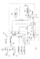
一方、携帯情報端末1には、室内用充電器80や車載用充電器90からの電力供給を受けて電池3を充電する充電回路20と、この充電回路20を制御する制御回路10とが設けられている。これら充電回路20及び制御回路10は、例えば図8のような構成をなしている。
On the other hand, the
制御回路10は、CPUなどによって構成されており、情報処理機能を有している。この制御回路10は、充電器識別信号1が入力される端子P1を備えると共に、端子T1に接続される端子P2と、端子T2に接続される端子P3と有しており、端子P2には後述する充電器識別信号2(後述)が入力されるようになっており、端子P3には、端子T2の電圧レベルを示す電圧レベル信号が入力されるようになっている。
The
また、制御回路10には、スイッチS1を制御するための制御端子P4と、スイッチS1を制御するための制御端子P5と、スイッチS3を制御するための制御端子P6とが設けられている。
Further, the
スイッチS1、S2、S3はいずれも半導体スイッチ(例えばトランジスタ等)により構成されている。スイッチS1は、端子P5からオン信号(例えばHレベル信号)が出力されているときにオン状態となるように構成されている。また、スイッチS3は,端子P6からオン信号(例えばHレベル信号)が出力されているときにオン状態となるように構成されている。また、スイッチS3は、端子P4からオン信号(例えばHレベル信号)が出力され、パワーオン回路42からオン信号が出力され、電源回路40から駆動電圧が出力されているときにオン状態となる構成をなしており、端子P4からオフ信号が出力されると、スイッチS3はオフ状態となるように構成されている。なお、パワーオン回路42は、利用者が所定の電源投入操作を行ったときにオン信号(例えばHレベル信号)を出力する回路である。
このように構成されているため、端子P5、P4、P6からの出力信号をそれぞれ制御することでスイッチS1,S2,S3のオンオフを制御できるようになっている。
All of the switches S1, S2, and S3 are constituted by semiconductor switches (for example, transistors). The switch S1 is configured to be in an on state when an on signal (for example, an H level signal) is output from the terminal P5. The switch S3 is configured to be in an on state when an on signal (for example, an H level signal) is output from the terminal P6. The switch S3 is turned on when an on signal (for example, an H level signal) is output from the terminal P4, an on signal is output from the power on
Since it is configured in this manner, on / off of the switches S1, S2, and S3 can be controlled by controlling output signals from the terminals P5, P4, and P6, respectively.
充電回路20は、端子T2に接続される充電ライン21を有しており、この充電ライン21を介して充電器(室内用充電器80や車載用充電器90)から充電電流が供給されるようになっている。
The charging
充電ライン21は、第1ライン22と、第2ライン23とに分岐されており、一方の第1ライン22には、ダイオードD1を介してスイッチS3が接続されている。なお、第1ライン22は、ダイオードD1の存在により、接続点A1側からスイッチS3側に電流が流れるように構成されている。また、第1ライン22は、電源回路40に接続されるライン24と、スイッチS2に接続されるライン25とに分岐しており、スイッチS3がオン状態となったときに端子T1と電源回路40との間が導通状態となり、スイッチS2,S3が共にオン状態となったときには端子T1と電池3との間が導通状態となるように構成されている。
The charging
充電ライン21から分岐する第2ライン23は、充電制御IC41に接続されている。この充電制御ICは公知の充電制御回路によって構成されており、定電流を出力する定電流制御や、定電圧を出力する定電圧制御が可能な構成となっている。充電制御ICからの出力ライン27には、抵抗R1,R2が直列に接続されており、抵抗R2の両端には、スイッチS1の両端がそれぞれ接続されている。スイッチS1は、充電制御IC41と接続点A2の間の抵抗値を切り替えるものであり、端子P5からオン信号が出力されてスイッチS1がオン状態となると、抵抗R2の両端が短絡状態となり、スイッチS1がオフ状態のときと比較して充電制御IC41と接続点A2との間の抵抗値が抵抗R2分だけ減少するようになっている。
A
また、携帯情報端末1には、図3等に示すように突起部91aと穴部55との嵌合を検出するスイッチSW1と、突起部92aと穴部56との嵌合を検出するスイッチSW2とが設けられており、図8に示す内部回路では、スイッチSW1,SW2がいずれもオン状態となったときに特定信号(Lレベル信号)が端子P1に入力され、それ以外のときには当該特定信号とは異なる信号(Hレベル信号)が端子P1に入力されるようになっている。
Further, as shown in FIG. 3 and the like, the
スイッチSW1は、例えば、ボタンスイッチとして構成されており、図3に示すように穴部55の底部に設けられ、図4に示すように穴部55内に突起部91aが挿入されたときにボタンが押されてオン状態となるように構成されている。スイッチSW2も同様であり、例えば、ボタンスイッチとして構成され、図3に示すように穴部56の底部に設けられている。そして、図4に示すように穴部56内に突起部92aが挿入されたときにボタンが押されてオン状態となるように構成されている。
The switch SW1, for example, is configured as a button switch, and is provided at the bottom of the
これらスイッチSW1,SW2は、図8、図9に示すように一端側が接地され、他端側がOR回路44に入力されるようになっている。スイッチSW1の他端側とOR回路44の間にはプルアップ抵抗R4を介してVccが接続されており、スイッチSW2の他端側とOR回路44の間にはプルアップ抵抗R5を介してVccが接続されている。このように構成されているため、スイッチSW1、SW2がいずれもオン状態となったときのみOR回路44からLレベル信号が出力され、いずれもオン状態となっていないとき若しくは一方のみがオン状態であるときにはOR回路44からHレベル信号が出力されるようになっている。なお、本実施形態では、端子P1に入力される信号を「充電器識別信号1」としており、スイッチSW1、SW2がいずれもオン状態となったときにOR回路44から出力されるLレベル信号、及びそれ以外のときにOR回路44から出力されるHレベル信号がこの「充電器識別信号1」に相当している。
These switches SW1 and SW2 are configured such that one end side is grounded and the other end side is input to the
また、携帯情報端末1には、図9のように3つの端子T1、T2、T3が設けられており、これら端子T1、T2、T3が、室内用充電器80の端子T21、T22、T23或いは車載用充電器90の端子T31、T32、T33に接続されるようになっている。端子T1は、制御回路10の端子P2と接続されており、端子T1と端子P2とを接続する接続ラインにはプルアップ抵抗R6を介してVccが接続されている。端子T1は、室内用充電器80が接続されたときに当該室内用充電器80の端子T21と接続される構成をなしており、その接続時には、トランジスタTrがオン状態に制御され、端子P2にLレベル信号が入力されるようになっている。また、車載用充電器90が接続されたときには端子T1と端子T31とが接続され、端子P2にはHレベル信号が入力されるようになっている。
Further, the
端子T2は、室内用充電器80のプラス側の出力端子T22又は車載用充電器90のプラス側の出力端子T32に接続されるようになっている。端子T2には電力ライン30が接続されており、この電力ライン30は、接続点A3から充電ライン23と信号ライン28とに分岐し、一方の充電ライン23に充電回路20が接続されている。また、他方の信号ライン28は制御回路10の端子P3に接続されており、接続点A3と端子P3の間には、ダイオードD2を介してVccが接続されている。また、接続点A3と端子P3の間の所定位置がダイオードD3を介してが接地されている。この構成では、端子T2に端子T22又は端子T32が接続されていないときには端子P3にLレベル信号が入力され、端子T22又は端子T32が接続されたときにはHレベル信号が入力される。
The terminal T2 is connected to the plus-side output terminal T22 of the
端子T3は、室内用充電器80のマイナス側の出力端子T23又は車載用充電器90のマイナス側の出力端子T33が接続されるようになっている。この端子T3には、接地ライン29が接続されている。
The terminal T3 is connected to the negative output terminal T23 of the
次に、充電制御について説明する。
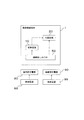
図10は、携帯情報端末1における充電制御処理の流れを例示するフローチャートである。
この充電制御処理は、制御回路10によって実行されるものであり、当該充電制御処理が開始されると、まず、携帯情報端末1が充電器に装着されたか否かを判断する処理が行われる(S10)。S10の判断処理では、端子P3の入力状態の確認が行われ、端子P3に充電出力信号(Hレベル信号)が入力されている場合には充電器に装着されたと判断しYesに進む。一方、端子P3にLレベル信号が入力されている場合には充電器に装着されていないと判断し、S10にてNoに進む。
なお、本実施形態では、制御回路10が「接続検出手段」の一例に相当し、接続部50と充電器との接続を検出するように機能している。
Next, charge control will be described.
FIG. 10 is a flowchart illustrating the flow of the charging control process in the
This charging control process is executed by the
In the present embodiment, the
S10にてYesに進む場合には、車載用充電器90が接続されているか否かを判別するための第1の判別処理を行う(S11)。この第1の判別処理では、車載用充電器90特有の突起部91a、92aがそれぞれ穴部55、56に挿入されているか否かを判断する。具体的には、端子P1に入力される充電器識別信号1が車載用充電器90を示すものであるか否かを確認する。例えば、端子P1にLレベル信号が入力されているときには、スイッチSW1、SW2がいずれもオンとなっており、突起部91a、92aがそれぞれ穴部55、56と嵌合しているといえるため、S11にてYesに進む。一方、端子P2にHレベル信号が入力されているときには、車載用充電器90が接続されていると判断できないため、S11にてNoに進む。
When the process proceeds to Yes in S10, a first determination process is performed to determine whether or not the in-
このように、本実施形態で用いられる車載用充電器90には「車載用特徴部」「嵌合部」として2つの突起部91a、92aが形成され、室内用充電器80にはこのような突起部が形成されておらず、携帯情報端末1では、2つのスイッチSW1、SW2(スイッチSW1、SW2は、「特徴検知部」「嵌合検知部」の一例に相当する)の両方で突起部91a、92aが検知された場合に車載用充電器90が接続されていると判断するようにしている。
As described above, the
S11にてYesに進むときには、車載用充電器90を判別する第2の判別処理を行う(S12)。この第2の判別処理では、端子P2に入力される充電器識別信号2が車載用充電器90を示すものであるか否かを確認する。本実施形態では、車載用充電器90が接続されているときには端子P2にHレベル信号が入力されるようになっているため、端子P2にHレベル信号が入力されている場合、S12にてYesに進む。逆に、充電器識別信号2が車載用充電器90を示すものでない場合(端子P2にLレベル信号が入力されている場合)、S12にてNoに進む。
When the process proceeds to Yes in S11, a second determination process for determining the in-
S12にてYesに進む場合とは、即ち、充電器識別信号1及び充電器識別信号2のいずれもが車載用充電器90の接続を示す場合であり、このときには信号状態に矛盾がなく、車載用充電器90が適切に接続され、かつ適切に作動しているといえる。従って、S13では、車載用充電器90に対応した充電制御処理を行う。
The case where the process proceeds to Yes in S12 is a case where both the
本実施形態では、充電器の用途毎に充電制御方式が定められており、S10にて充電器の接続が検出されたとき、判別された充電器の用途に対応した方式で電池3の充電制御を行っている。即ち、室内用充電器80に対応して室内用の充電方式が定められ、車載用充電器90に対応して車載用の充電方式が定められており、S13に到る場合のように車載用充電器90が接続されたと判別されるような場合には車載用の充電方式で電池3の充電制御が行われる。一方、後述するS17に到る場合のように室内用充電器80が接続されたと判別される場合には、室内用の充電方式で電池3の充電制御が行われる。なお、図11には、充電器識別信号1、2及び充電出力信号の状態と、充電器について予想される状態との対応関係を示している。
In this embodiment, a charge control method is determined for each use of the charger. When the connection of the charger is detected in S10, the charge control of the
図12には、充電器の接続状態とスイッチS1〜S3の制御との対応関係を示している。S13の処理では、車載用充電器90が正常に接続されているとして車載用の充電方式で充電が行われるが、この方式では、スイッチS1をオフ状態とし、スイッチS2をオン状態とし、スイッチS3をオフ状態とするように制御を行う。まず、図8に示す充電回路20においてスイッチS1がオフ状態となるので、充電制御IC41からの出力ライン27には抵抗R1,R2が直列に介在することになり、スイッチS1がオン状態のとき(後述する室内用の充電方式のとき)と比較して出力ライン27の充電電流が抑えられる(例えば、例えば抵抗R1と抵抗R2の抵抗値を同一とすると、充電電流が半分程度に抑えられる)。また、スイッチS3がオフ状態であり、スイッチS2がオン状態であるので、車載用充電器90から第1ライン22を介して電源回路40に電力が供給されず、車載用充電器90からの電力は、充電制御IC41、出力ライン27を通る経路で電源回路40に供給される。また、車載用充電器90からの充電電流は、充電制御IC41、出力ライン27を通る経路で電池3に供給される。なお、この場合、充電制御IC41から出力される充電電流のうち、電源回路40に供給される分を除いた分が電池3に供給されることとなる。
FIG. 12 shows the correspondence between the connection state of the charger and the control of the switches S1 to S3. In the process of S13, charging is performed by the on-vehicle charging method assuming that the on-
一方、S12において端子P2にHレベル信号が入力されていない場合(つまり、充電器識別信号1がLレベルであり、充電器識別信号2がHレベルの場合)には、車載用充電器90は接続されているものの、充電器識別信号2が正常でなく、車載用充電器90に異常が生じていると推定できるので、この場合には充電を中止する(S14)。なお、S14の処理において、車載用充電器90が正常でない旨のエラー情報を当該携帯情報端末1に設けられた液晶表示器などに表示するようにしてもよい。
On the other hand, when the H level signal is not input to the terminal P2 in S12 (that is, when the
次に、S11にてNoに進む場合について説明する。S11にてNoに進む場合にも、車載用充電器90を判別する第2の判別処理が行われる(S15)。この処理も基本的にS12と同様であり、端子P2に入力される充電器識別信号2が車載用充電器90を示すものであるか否かを確認する。上述したように、車載用充電器90が接続されているときには端子P2にHレベル信号が入力されるようになっているため、端子P2にHレベル信号が入力されている場合、S15にてYesに進む。逆に、充電器識別信号2が車載用充電器90を示すものでない場合(端子P2にLレベル信号が入力されている場合)、S15にてNoに進む。
Next, the case where it progresses to No in S11 is demonstrated. Even when the process proceeds to No in S11, a second determination process for determining the in-
S15にてNoに進む場合とは、即ち、充電器識別信号1及び充電器識別信号2のいずれもが室内用充電器80の接続を示す場合であり、このときには信号状態に矛盾がなく、室内用充電器80が適切に接続され、かつ適切に作動しているといえる。従って、S17では、室内用充電器80に対応した充電制御処理を行う。
The case where the process proceeds to No in S15 is a case where both the
S17の処理では、室内用充電器80が正常に接続されているとして室内用の充電方式で充電を行うこととなるが、この方式では、図12のようにスイッチS1をオン状態とし、スイッチS2をオフ状態とし、スイッチS3をオン状態とするように制御を行う。この場合、図8の充電回路20においてスイッチS1がオン状態となるので、充電制御IC41からの出力ライン27において抵抗R2の両端が短絡し、出力ライン27には実質的に抵抗R1のみが介在することになる。この場合、スイッチS1がオフ状態のとき(上述した車載用の充電方式のとき)と比較して出力ライン27の充電電流が増大する。従って、より大きな充電電流で電池3の充電が行われることとなる。このように、本実施形態では、制御回路10によるスイッチS1の制御により、車載用充電器90が接続部50に接続されているときに電池3に供給する充電電流を、室内用充電器80が接続部50に接続されているときに電池3に供給する充電電流よりも電流量を少なくしている。
In the process of S17, the
また、スイッチS3がオン状態であり、スイッチS2がオフ状態であるので、車載用充電器90からの電力は、第1ライン22を通って電源回路40に直接供給され、電池3から電源回路40へ電力供給は遮断される。
In addition, since the switch S3 is in the on state and the switch S2 is in the off state, the power from the in-
一方、S15において端子P2にHレベル信号が入力されている場合(つまり、充電器識別信号1がHレベルであり、充電器識別信号2がHレベルの場合)には、車載用充電器90が接続されているが、充電器識別信号1が正常でなく、車載用充電器90の突起部91a、92aと穴部55、56との嵌合が正常でない状態(ロック異常状態)と推定できるので、この場合には充電を中止する(S16)。なお、S16の処理において、車載用充電器90にロック異常が発生している旨のエラー情報を当該携帯情報端末1に設けられた液晶表示器などに表示するようにしてもよい。
On the other hand, when the H level signal is input to the terminal P2 in S15 (that is, when the
なお、図12に示すように、携帯情報端末1が動作中(電源ON状態)で、且つ充電器が接続されていないときには、スイッチS1、S3をオフ状態とすると共に、スイッチS2をオン状態とする制御が行われ、電池3から電源回路40に電力が供給される。また、携帯情報端末1が電源OFF状態で、且つ充電器が接続されていないときにはスイッチS1〜S3がいずれもオフ状態とされる。
In addition, as shown in FIG. 12, when the
以上説明した本実施形態の例では、車載用充電器90において、接続部50との接続時に第1状態(Hレベル状態)となる端子T31(第1識別端子)が設けられ、室内用充電器80において、接続部50との接続時に第1状態とは異なる第2状態(Lレベル状態)となる端子T31(第2識別端子)が設けられており、更に、接続部50には、車載用充電器90との接続時に端子T31(第1識別端子)と接続し、室内用充電器80との接続時に端子T21(第2識別端子)と接続する端子T1(接続端子)が設けられている。そして、スイッチSW1、SW2(嵌合検知部)による嵌合検知結果(即ち、突起部91a、92a(嵌合部)と穴部55,56(被嵌合部)との嵌合の検知結果)、及び端子T1(接続端子)の状態(即ち、端子T1が第1状態及び第2状態のいずれの状態であるか)に基づいて、接続部50に接続される充電器の用途判別、及びその接続される充電器の異常状態の判別を行っている。
In the example of the present embodiment described above, the in-
なお、本実施形態では、スイッチSW1、SW2、OR回路44、制御回路10によって「判別手段」が構成されており、各種類の充電器の構成に基づき、接続が検出された充電器の用途を判別するように機能している。
また、制御回路10は、「充電制御手段」の一例に相当し、電池3の充電制御を行うように機能している。
In the present embodiment, the switches SW1, SW2, the
The
なお、図10のフローチャートでは省略しているが、S10にてNoに進む場合(端子P3の充電出力信号がLレベルの場合)、図11下段のように状態を推定できる。例えば、充電器識別信号1、2がいずれもHレベルであり、かつ端子P3にLレベル信号が入力されている場合には、充電器が接続されていないと推定できるため、その旨の情報を液晶表示器などに表示するようにしてもよい。また、充電器識別信号1がHレベルであり、充電器識別信号2がLレベルであるが端子P3にはLレベル信号が入力されている場合、室内用充電器80が接続されているもののその出力が異常であると推定できるため、その旨の情報を液晶表示器などに表示するようにしてもよい。また、充電器識別信号1がLレベルであり、充電器識別信号2がHレベルであるが端子P3にはLレベル信号が入力されている場合、車載用充電器90が接続されているものの出力がなされていないと推定できるため、その旨の情報を液晶表示器などに表示するようにしてもよい。また、充電器識別信号1、2がいずれもLレベルであり、端子P3にLレベル信号が入力されている場合、車載用充電器90が接続されているもののステータス又は出力異常が生じていると推定できるためその旨の情報を液晶表示器などに表示するようにしてもよい。
Although omitted in the flowchart of FIG. 10, when the process proceeds to No in S10 (when the charge output signal of the terminal P3 is L level), the state can be estimated as shown in the lower part of FIG. For example, when the charger identification signals 1 and 2 are both at the H level and the L level signal is input to the terminal P3, it can be estimated that the charger is not connected. You may make it display on a liquid crystal display. When the
本実施形態の構成によれば、例えば以下のような効果を奏する。
本実施形態に係る携帯情報端末1では、充電器の用途毎に充電制御方式が定められており、接続が検出された充電器の用途に対応した方式で電池3の充電制御を行っている。このようにすると、充電器の用途毎に充電制御方式を変更でき、各用途に適した充電制御を行うことができるようになる。従って、全ての充電器種別に対して同一の充電制御方式を用いる構成と比較して、より適切で効率的な充電制御が可能となる。
According to the configuration of the present embodiment, for example, the following effects can be obtained.
In the
また、所定構成の室内用充電器80と、当該室内用充電器80とは構成の異なる車載用充電器90と、が接続可能とされると共に、室内用充電器80に対応して室内用の充電方式が定められ、車載用充電器90に対応して車載用の充電方式が定められている。このようにすると、充電場所が室内であるか車内であるかを適切に判断できると共に、環境が異なる室内と車内とで充電方式を変えることができる。そして、室内においては室内に適した充電制御を行うことができ、車内においては車内に適した充電制御を行うことができるようになる。
Further, the
また、車載用充電器90が接続部50に接続されているときに電池3に供給する充電電流を、室内用充電器80が接続部50に接続されているときに電池3に供給する充電電流よりも電流量を少なくしている。
車載用充電器90が接続されている場合(即ち、車内で充電される場合)、室内で充電される場合と比較して携帯情報端末1の周囲温度が高くなりやすいが、本発明のように車載用充電器90の接続時に充電量を少なくする制御を行うようにすれば、高温となりやすい車両内において電池や周囲部品、或いは充電器の温度上昇を抑えることができ、高温化に伴う不具合を効果的に抑制できる。
また、車載用充電器90で充電される場合、統計的に使用した分だけ補充電する使われ方が一般的であり、急速充電はあまり必要でない場合が多い。従って、充電電流が抑えられても不都合が生じ難く、車載環境に極めて適した充電を行うことができる。
Further, the charging current supplied to the
When the in-
In addition, when charging with the in-
逆に、室内で充電されるときには、車載環境と比較して温度条件等が厳しくないため、本実施形態のように室内用充電器80が接続されるときに充電電流を増大させても不具合が生じ難く、従って、急速充電を良好に行うことができる。また、電源回路40への電力供給と、電池3への充電電流の供給を別々の経路で行っているため、電池3により多くの充電電流を供給でき、充電時間をより短縮できる。
On the contrary, when charging indoors, the temperature conditions are not so strict as compared with the in-vehicle environment, so there is a problem even if the charging current is increased when the
また、本実施形態に係る携帯情報端末1は、車載用充電器90に複数形成され且つ室内用充電器80に形成されていない突起部(車載用特徴部)を検知するスイッチSW1、SW2(特徴検知部)を備えており、それら複数の特徴検知部の全てで突起部(車載用特徴部)が検知された場合に車載用充電器90が接続されていると判断している。このように複数の車載用特徴部の全てを検出する構成とすれば、車載用充電器90が接続されているか否かを精度高く判断できるようになる。
In addition, the
また、車載用充電器90に形成され且つ室内用充電器80に形成されていない突起部91a、92a(嵌合部)と嵌合する穴部55、56(被嵌合部)を備えており、装置本体2が車載用充電器90に保持される際に、突起部91a、92aがそれぞれ穴部55,56と嵌合して車載用充電器90に組み付けられる構成となっている。このようにすると、比較的振動を伴う車両内において携帯情報端末1を充電器に安定的に組み付けることができ、車両に比べて振動のない室内においては突起部91a、92aを嵌合させずに着脱の容易化を図ることができる。さらに、突起部91a、92a(嵌合部)と穴部55、56(被嵌合部)とを利用して車載用充電器90が接続されているか否かを検出しており、このようにすれば、車載用と室内用とを判断するための特別構成を別途多く用意する必要がなく、携帯情報端末1及び車載用充電器90における振動に対応するための特徴構成を用いて車載用か室内用かを適切に判断できるようになる。
Moreover, it has the
また、装置本体2が車載用充電器90に装着される際に突起部91a、92a(嵌合部)を穴部55,56側(被嵌合部側)に案内するガイド溝53,54を備えており、このガイド溝53、54内において穴部55、56がそれぞれ形成されている。このようにすると携帯情報端末1を車載用充電器90に装着する装着操作において、装置本体2が車載用充電器90の適切な位置に案内されやすくなり、車載用充電器90に対する装置本体2の位置決め、装着操作を容易に行うことができるようになる。
Further, when the apparatus
また、ガイド溝53,54が室内用充電器80に形成されたガイドリブ81,82のガイドに兼用される構成をなしており、穴部55、56がガイド溝53、54の溝底よりも更に奥まった位置に凹状に形成されている。このようにすると、ガイド溝53、54によって室内用充電器80を適切な位置に位置決めすることができ、更に、そのガイド溝53,54を、室内用充電器80の位置決めと、突起部91a、92aの案内とに兼用できるようになる。
The
また、スイッチSW1,SW2(嵌合検知部)による突起部91a、92aと穴部55,56との嵌合の検知結果、及び端子T1(接続端子)の状態に基づいて、接続部50に接続される充電器の用途判別、及びその接続される充電器の異常状態の判別を行っている。このようにすると、接続される充電器の用途をより確実に判別でき、また、充電器の異常状態をも判別できるため、接続される充電器の用途及び充電器の異常状態を反映したより一層適切な充電制御を行うことができるようになる。
Further, the connection to the
[他の実施形態]
本発明は上記記述及び図面によって説明した実施形態に限定されるものではなく、例えば次のような実施形態も本発明の技術的範囲に含まれる。
[Other Embodiments]
The present invention is not limited to the embodiments described with reference to the above description and drawings. For example, the following embodiments are also included in the technical scope of the present invention.
上記実施形態では、複数種類の充電器の例として、車載用充電器と室内用充電器を例示したが、用途の異なる充電器であればこれ以外の組み合わせであってもよい。例えば、上記実施形態のいずれか又は両方を別の用途(例えば、電車用、航空機用等)の充電器に変更し、各充電器の用途に応じた充電方式をそれぞれ用いてもよい。 In the said embodiment, although the vehicle-mounted charger and the indoor charger were illustrated as an example of multiple types of charger, as long as it is a charger from which an application differs, other combinations may be sufficient. For example, either or both of the above embodiments may be changed to a charger for another application (for example, for trains, aircraft, etc.), and a charging method corresponding to the application of each charger may be used.
上記実施形態では、車載用特徴部の一例として突起部91a、92aを例示したが、車載用特徴部はこれに限られない。例えば、車載用充電器を図5のような室内用充電器80と同様の構成とし、室内用充電器を、図5からガイドリブを省略した構成とすることもできる。この場合、車載用充電器が載置される場合のみガイドリブがガイド溝53、54内に進入することとなるため、ガイド溝53、54の溝底等に上記実施形態と同様のスイッチSW1、SW2を設けておき、これらスイッチSW1,SW2によって車載用充電器に設けられる2つのガイドリブが検出されたときに車載用充電器が接続されていると判断するように構成すればよい。
In the said embodiment, although
上記実施形態では特に言及はしていないが、例えば、電池3の内部又は周囲に当該電池3の温度を検出する温度検出手段(例えばサーミスタ等)を設けておき、この温度検出手段によって検出される電池3の温度が閾値を超えた場合に、電池3の充電を遮断又は抑制するように制御を行うこともできる。
具体的には、例えば、サーミスタ等の温度検出手段を電池3の内部又は周囲に配置し、その温度検出手段からの温度信号が制御回路10に入力されるように構成し、制御回路10においては、予め2つの閾値(第1の値と、当該第1の値よりも低い第2の値)を用意(例えば図示しないメモリに記憶)しておく。また、充電制御IC41からの出力ライン27など充電電流が流れるラインに制御回路10によってオンオフ制御される半導体スイッチ(トランジスタ等)を用意しておく。
このような構成とした上で、制御回路10を、室内用充電器80が接続部50に接続されているときに閾値を第1の値に設定し、車載用充電器90が接続部50に接続されているときに閾値を第1の値よりも低い第2の値に設定する制御を行う構成とする。
このようにすると、接続部50に室内用充電器80が接続されているときには制御回路10において閾値が第1の値に設定され、温度検出手段にて検出される電池3の温度が第1の値に達したときに出力ライン27等に配置される半導体スイッチがオフ状態に制御され充電電流の供給が遮断されるようになる。また、接続部50に車載用充電器90が接続されているときには、制御回路10により閾値が第1の値よりも低い第2の値に設定され、温度検出手段にて検出される電池3の温度が第2の値に達したときに出力ライン27等に配置される半導体スイッチがオフ状態に制御され充電電流の供給が遮断されるようになる。
このようにすると、電池3の過熱を適切に検出でき、電池3を効果的に保護できる。また、室内用充電器80が接続部50に接続されているときに閾値を第1の値に設定し、車載用充電器90が接続部50に接続されているときに閾値を第1の値よりも低い第2の値に設定する制御を行っているため、室内で充電を行う際の過熱保護の水準を適切なレベルに定めることができ、高温になりやすい車両内での充電については、室内よりも過熱保護の水準を引き上げて電池3や周囲部品、或いは充電器を効果的に保護できるようになる。
Although not particularly mentioned in the above embodiment, for example, temperature detection means (for example, a thermistor) for detecting the temperature of the
Specifically, for example, a temperature detection unit such as a thermistor is disposed inside or around the
With this configuration, the
In this way, when the
If it does in this way, overheating of
1…携帯情報端末
2…装置本体
4…電池
10…制御回路(接続検出手段、判別手段、充電制御手段)
50…接続部(接続手段)
51,52…係合部
53,54…ガイド溝
55,56…穴部(被嵌合部)
80…室内用充電器(充電器)
81,82…ガイドリブ
90…車載用充電器(充電器)
91,92…被係合部
91a,92a…突起部(嵌合部、車載用特徴部)
T1…端子(接続端子)
T21…端子(第2識別端子)
T31…端子(第1識別端子)
SW1,SW2…検知スイッチ(特徴検知部、嵌合検知部、判別手段)
DESCRIPTION OF
50 .. connection part (connection means)
51, 52 ... engaging
80 ... Indoor charger (charger)
81, 82 ... guide
91, 92 ... engaged
T1 ... terminal (connection terminal)
T21 ... terminal (second identification terminal)
T31 ... terminal (first identification terminal)
SW1, SW2 ... detection switch (feature detection unit, fitting detection unit, discrimination means)
Claims (9)
前記装置本体に設けられ、構成及び用途の異なる複数種類の充電器が接続可能に構成された接続手段と、
前記接続手段と前記充電器との接続を検出する接続検出手段と、
各種類の前記充電器の構成に基づき、前記接続検出手段により接続が検出された前記充電器の用途を判別する判別手段と、
前記電池の充電制御を行う充電制御手段と、
を備え、
前記充電制御手段は、前記充電器の用途毎に充電制御方式が定められており、前記接続検出手段により前記充電器の接続が検出されたとき、前記判別手段によって判別された前記充電器の用途に対応した方式で前記電池の充電制御を行うことを特徴とする携帯情報端末。 A portable information terminal in which a rechargeable battery is accommodated in the apparatus body,
A connecting means provided in the apparatus main body, and configured to connect a plurality of types of chargers having different configurations and uses;
Connection detecting means for detecting connection between the connecting means and the charger;
Based on the configuration of each type of the charger, a determination unit that determines the use of the charger whose connection is detected by the connection detection unit;
Charging control means for controlling charging of the battery;
With
The charging control means has a charging control method defined for each use of the charger, and when the connection of the charger is detected by the connection detecting means, the use of the charger determined by the determining means A portable information terminal that performs charge control of the battery by a method corresponding to the above.
前記充電制御手段は、前記室内用充電器に対応して室内用の充電方式が定められ、前記車載用充電器に対応して車載用の充電方式が定められており、前記判別手段によって前記室内用充電器と判別された場合には前記室内用の充電方式で前記電池の充電制御を行い、前記車載用充電器と判別された場合には前記車載用の充電方式で前記電池の充電制御を行うことを特徴とする請求項1に記載の携帯情報端末。 The connecting means is connectable to an indoor charger having a predetermined configuration and an in-vehicle charger having a different configuration from the indoor charger.
The charging control means has an indoor charging method corresponding to the indoor charger, and an in-vehicle charging method corresponding to the in-vehicle charger. If the battery charger is determined to be a vehicle charger, the battery charging control is performed using the indoor charging method. If the battery charger is determined to be a vehicle charger, the battery charging control is performed using the vehicle charging method. The portable information terminal according to claim 1, wherein the portable information terminal is performed.
前記充電制御手段は、前記温度検出手段によって検出される前記電池の温度が閾値を超えた場合に、前記電池の充電を遮断又は抑制する構成をなしており、
更に、充電制御手段は、前記室内用充電器が前記接続手段に接続されているときに前記閾値を第1の値に設定し、前記車載用充電器が前記接続手段に接続されているときに前記閾値を前記第1の値よりも低い第2の値に設定する制御を行うことを特徴とする請求項2又は請求項3に記載の携帯情報端末。 Temperature detecting means for detecting the temperature of the battery,
The charging control unit is configured to block or suppress charging of the battery when the temperature of the battery detected by the temperature detection unit exceeds a threshold value,
Furthermore, the charging control means sets the threshold value to the first value when the indoor charger is connected to the connecting means, and when the in-vehicle charger is connected to the connecting means. The portable information terminal according to claim 2 or 3, wherein control is performed to set the threshold value to a second value lower than the first value.
前記装置本体は、前記車載用充電器に保持される際に、前記嵌合部と前記被嵌合部とが嵌合して前記車載用充電器に組み付けられる構成をなしており、
前記判別手段は、前記嵌合部と前記被嵌合部との嵌合を検知する嵌合検知部を備え、前記嵌合検知部により前記被係合部と前記係合部との嵌合が検知された場合に前記車載用充電器が接続されていると判断することを特徴とする請求項2から請求項5のいずれか一項に記載の携帯情報端末。 The connecting means includes a fitted portion that is fitted to a fitting portion that is formed in the in-vehicle charger and is not formed in the indoor charger,
The apparatus body is configured to be assembled to the on-vehicle charger by fitting the fitting portion and the fitted portion when held by the on-vehicle charger,
The discriminating means includes a fitting detection unit that detects fitting between the fitting portion and the fitted portion, and the fitting detection portion causes the fitting portion and the engaging portion to be fitted. The portable information terminal according to any one of claims 2 to 5, wherein when detected, the on-vehicle charger is determined to be connected.
前記被嵌合部は、前記ガイド溝の溝底よりも更に奥まった位置に凹状に形成されていることを特徴とする請求項7に記載の携帯情報端末。 The guide groove is configured to serve as a guide for a guide rib formed in the indoor charger,
The portable information terminal according to claim 7, wherein the fitted portion is formed in a concave shape at a position deeper than a groove bottom of the guide groove.
前記接続手段は、前記車載用充電器の接続時に前記第1識別端子と接続し、前記室内用充電器の接続時に前記第2識別端子と接続する接続端子を備え、
前記判別手段は、前記嵌合検知部による前記嵌合部と前記被嵌合部との嵌合の検知結果、及び前記接続端子の状態に基づいて、前記接続手段に接続される前記充電器の用途判別、及びその接続される前記充電器の異常状態の判別を行うことを特徴とする請求項6から請求項8のいずれか一項に記載の携帯情報端末。 The on-vehicle charger includes a first identification terminal that is in a first state when connected to the connecting means, and the indoor charger is different from the first state when connected to the connecting means. Comprising a second identification terminal in a second state;
The connection means includes a connection terminal that is connected to the first identification terminal when the on-vehicle charger is connected, and is connected to the second identification terminal when the indoor charger is connected;
The determination means is based on a result of detection of the fitting between the fitting portion and the fitted portion by the fitting detection portion, and a state of the connection terminal of the charger connected to the connection means. The portable information terminal according to any one of claims 6 to 8, wherein the portable information terminal performs use determination and determination of an abnormal state of the charger connected thereto.
Priority Applications (1)
| Application Number | Priority Date | Filing Date | Title |
|---|---|---|---|
| JP2008197477A JP5077129B2 (en) | 2008-07-31 | 2008-07-31 | Portable information terminal |
Applications Claiming Priority (1)
| Application Number | Priority Date | Filing Date | Title |
|---|---|---|---|
| JP2008197477A JP5077129B2 (en) | 2008-07-31 | 2008-07-31 | Portable information terminal |
Publications (2)
| Publication Number | Publication Date |
|---|---|
| JP2010035384A true JP2010035384A (en) | 2010-02-12 |
| JP5077129B2 JP5077129B2 (en) | 2012-11-21 |
Family
ID=41739199
Family Applications (1)
| Application Number | Title | Priority Date | Filing Date |
|---|---|---|---|
| JP2008197477A Expired - Fee Related JP5077129B2 (en) | 2008-07-31 | 2008-07-31 | Portable information terminal |
Country Status (1)
| Country | Link |
|---|---|
| JP (1) | JP5077129B2 (en) |
Cited By (2)
| Publication number | Priority date | Publication date | Assignee | Title |
|---|---|---|---|---|
| CN103617531A (en) * | 2013-12-16 | 2014-03-05 | 信雅达系统工程股份有限公司 | Safety payment method and device based on credible two-dimension code |
| JP2015116080A (en) * | 2013-12-13 | 2015-06-22 | パイオニア株式会社 | Portable terminal, charge control method, and program |
Citations (4)
| Publication number | Priority date | Publication date | Assignee | Title |
|---|---|---|---|---|
| JP2001174888A (en) * | 1999-12-14 | 2001-06-29 | Olympus Optical Co Ltd | Camera |
| JP2002345159A (en) * | 2001-05-08 | 2002-11-29 | Internatl Business Mach Corp <Ibm> | Power supply system, computer device, battery, protecting method for abnormal charging, and program |
| JP2003009413A (en) * | 2001-06-20 | 2003-01-10 | Kyocera Corp | Charge control equipment of secondary battery |
| JP2005333794A (en) * | 2004-04-22 | 2005-12-02 | Nec Saitama Ltd | Portable electronic devices and mobile telecommunication terminal |
-
2008
- 2008-07-31 JP JP2008197477A patent/JP5077129B2/en not_active Expired - Fee Related
Patent Citations (4)
| Publication number | Priority date | Publication date | Assignee | Title |
|---|---|---|---|---|
| JP2001174888A (en) * | 1999-12-14 | 2001-06-29 | Olympus Optical Co Ltd | Camera |
| JP2002345159A (en) * | 2001-05-08 | 2002-11-29 | Internatl Business Mach Corp <Ibm> | Power supply system, computer device, battery, protecting method for abnormal charging, and program |
| JP2003009413A (en) * | 2001-06-20 | 2003-01-10 | Kyocera Corp | Charge control equipment of secondary battery |
| JP2005333794A (en) * | 2004-04-22 | 2005-12-02 | Nec Saitama Ltd | Portable electronic devices and mobile telecommunication terminal |
Cited By (3)
| Publication number | Priority date | Publication date | Assignee | Title |
|---|---|---|---|---|
| JP2015116080A (en) * | 2013-12-13 | 2015-06-22 | パイオニア株式会社 | Portable terminal, charge control method, and program |
| CN103617531A (en) * | 2013-12-16 | 2014-03-05 | 信雅达系统工程股份有限公司 | Safety payment method and device based on credible two-dimension code |
| CN103617531B (en) * | 2013-12-16 | 2016-08-24 | 信雅达系统工程股份有限公司 | Safe payment method based on credible two-dimension code and device |
Also Published As
| Publication number | Publication date |
|---|---|
| JP5077129B2 (en) | 2012-11-21 |
Similar Documents
| Publication | Publication Date | Title |
|---|---|---|
| JP4123517B2 (en) | Battery device | |
| JP4462112B2 (en) | Electric tool | |
| JP4221677B2 (en) | Battery device | |
| JP3583143B2 (en) | Modular battery pack | |
| JP6195233B2 (en) | Battery pack, charging system and power tool | |
| EP2246920B1 (en) | Battery device and electronic apparatus | |
| JP5077129B2 (en) | Portable information terminal | |
| JP2008024194A (en) | Mounting unit of vehicle-mounted type driving recorder | |
| JP2006186045A (en) | Mounting structure of electronic equipment | |
| JP4635597B2 (en) | Electronics and batteries | |
| JP2022047802A (en) | Electronic apparatus, battery pack, control method and program | |
| JP5037218B2 (en) | Charge control circuit |
Legal Events
| Date | Code | Title | Description |
|---|---|---|---|
| A621 | Written request for application examination |
Free format text: JAPANESE INTERMEDIATE CODE: A621 Effective date: 20100727 |
|
| A977 | Report on retrieval |
Free format text: JAPANESE INTERMEDIATE CODE: A971007 Effective date: 20120214 |
|
| A131 | Notification of reasons for refusal |
Free format text: JAPANESE INTERMEDIATE CODE: A131 Effective date: 20120507 |
|
| A521 | Request for written amendment filed |
Free format text: JAPANESE INTERMEDIATE CODE: A523 Effective date: 20120704 |
|
| TRDD | Decision of grant or rejection written | ||
| A01 | Written decision to grant a patent or to grant a registration (utility model) |
Free format text: JAPANESE INTERMEDIATE CODE: A01 Effective date: 20120731 |
|
| A01 | Written decision to grant a patent or to grant a registration (utility model) |
Free format text: JAPANESE INTERMEDIATE CODE: A01 |
|
| A61 | First payment of annual fees (during grant procedure) |
Free format text: JAPANESE INTERMEDIATE CODE: A61 Effective date: 20120813 |
|
| FPAY | Renewal fee payment (event date is renewal date of database) |
Free format text: PAYMENT UNTIL: 20150907 Year of fee payment: 3 |
|
| R150 | Certificate of patent or registration of utility model |
Ref document number: 5077129 Country of ref document: JP Free format text: JAPANESE INTERMEDIATE CODE: R150 Free format text: JAPANESE INTERMEDIATE CODE: R150 |
|
| R250 | Receipt of annual fees |
Free format text: JAPANESE INTERMEDIATE CODE: R250 |
|
| R250 | Receipt of annual fees |
Free format text: JAPANESE INTERMEDIATE CODE: R250 |
|
| R250 | Receipt of annual fees |
Free format text: JAPANESE INTERMEDIATE CODE: R250 |
|
| R250 | Receipt of annual fees |
Free format text: JAPANESE INTERMEDIATE CODE: R250 |
|
| R250 | Receipt of annual fees |
Free format text: JAPANESE INTERMEDIATE CODE: R250 |
|
| R250 | Receipt of annual fees |
Free format text: JAPANESE INTERMEDIATE CODE: R250 |
|
| LAPS | Cancellation because of no payment of annual fees |