JP2005333794A - Portable electronic devices and mobile telecommunication terminal - Google Patents
Portable electronic devices and mobile telecommunication terminal Download PDFInfo
- Publication number
- JP2005333794A JP2005333794A JP2005085623A JP2005085623A JP2005333794A JP 2005333794 A JP2005333794 A JP 2005333794A JP 2005085623 A JP2005085623 A JP 2005085623A JP 2005085623 A JP2005085623 A JP 2005085623A JP 2005333794 A JP2005333794 A JP 2005333794A
- Authority
- JP
- Japan
- Prior art keywords
- charging
- unit
- charging current
- storage battery
- current
- Prior art date
- Legal status (The legal status is an assumption and is not a legal conclusion. Google has not performed a legal analysis and makes no representation as to the accuracy of the status listed.)
- Granted
Links
Images


Classifications
-
- Y—GENERAL TAGGING OF NEW TECHNOLOGICAL DEVELOPMENTS; GENERAL TAGGING OF CROSS-SECTIONAL TECHNOLOGIES SPANNING OVER SEVERAL SECTIONS OF THE IPC; TECHNICAL SUBJECTS COVERED BY FORMER USPC CROSS-REFERENCE ART COLLECTIONS [XRACs] AND DIGESTS
- Y02—TECHNOLOGIES OR APPLICATIONS FOR MITIGATION OR ADAPTATION AGAINST CLIMATE CHANGE
- Y02E—REDUCTION OF GREENHOUSE GAS [GHG] EMISSIONS, RELATED TO ENERGY GENERATION, TRANSMISSION OR DISTRIBUTION
- Y02E60/00—Enabling technologies; Technologies with a potential or indirect contribution to GHG emissions mitigation
- Y02E60/10—Energy storage using batteries
Abstract
Description
本発明は、携帯型の電子機器及び移動体通信端末に関し、充電中に使用しても筐体表面が高温にならない携帯型電子機器及び移動体通信端末に関する。 The present invention relates to a portable electronic device and a mobile communication terminal, and more particularly to a portable electronic device and a mobile communication terminal whose casing surface does not become hot even when used during charging.
近年、携帯型の電子機器としては、移動体通信端末、電子手帳、PDAなどが普及している。携帯型の電子機器は、端末の小型化・薄型化・軽量化に伴って、筐体に内蔵された発熱源(スピーカ、撮像素子、充電中の蓄電池、充電回路など)から筐体表面までの熱抵抗(空間的な距離)が減少しており、回路動作による筐体表面の温度上昇が大きくなる傾向にある。換言すると、移動体通信端末の小型化・薄型化・軽量化に伴って、筐体内部の発熱源で発生した熱が筐体へと伝わりやすくなっており、筐体表面が高温になりやすくなっている。 In recent years, mobile communication terminals, electronic notebooks, PDAs, and the like have become widespread as portable electronic devices. As portable electronic devices become smaller, thinner, and lighter, the heat sources (speakers, image sensors, rechargeable batteries, charging circuits, etc.) built into the case to the case surface Thermal resistance (spatial distance) is decreasing, and the temperature rise on the housing surface due to circuit operation tends to increase. In other words, as the mobile communication terminal becomes smaller, thinner, and lighter, heat generated by a heat source inside the housing is easily transferred to the housing, and the surface of the housing is likely to become hot. ing.
移動体通信端末における発熱源のうち「蓄電池を充電中の充電回路」は、移動体通信端末が通信状態にあると発熱量が大きくなる。移動体通信端末を通信に用いる場合、端末はユーザの顔に近づけた状態で使用されることが多いため、充電中に移動体通信端末を使用すると(通信状態にすると)、筐体の表面温度が上昇してユーザに不快感を与えることもあり得る。 Of the heat generation sources in the mobile communication terminal, the “charging circuit charging the storage battery” generates a large amount of heat when the mobile communication terminal is in communication. When using a mobile communication terminal for communication, the terminal is often used in the state of being close to the user's face, so if the mobile communication terminal is used during charging (when in communication), the surface temperature of the housing May rise and cause discomfort to the user.
移動体通信端末の筐体表面の温度上昇を抑止することに関する従来技術としては、特許文献1に開示される「充電方式」がある。特許文献1に開示される発明は、無線装置の使用時における充電電流を減少させることにより、電源部の大容量化を防止して充電器の小型化を可能とする充電方式である。
しかし、特許文献1に開示される発明は、充電回路を無線装置(移動体通信端末)側に有していない。すなわち、特許文献1に開示される発明は、充電回路を備えた携帯型電子機器における発熱の防止を目的とするものではない。
具体的には、特許文献1に開示される発明は、充電器側からの制御によって無線装置内のスイッチを切り替えているが、このような構成とした場合には、専用の充電器と無線装置とを対として用いなければならない。すると、外出先で充電する必要が生じた場合のように、専用の充電器を用いることができない時には充電電流が減少せず、電池の発熱を避けることができないという問題が生じる。移動体通信端末に代表される携帯型電子機器は、旅行先や出張先などで他人の充電器を借用して蓄電池を充電しなければならないこともあるため、専用の充電器を用いなければ効果が得られないことは好ましいことではない。
However, the invention disclosed in
Specifically, the invention disclosed in
また、特許文献1には、電源部と電池との双方から無線部へ給電される構成が図示されているが、電源部の出力電圧と電池電圧とは同じではなく(電源部出力電圧>電池電圧)、しかも電池電圧は充電の度合に応じて変動する。よって、実際には、無線部は、電源部及び電池のそれぞれとの間に図示されていないレギュレータを必要とするため、回路規模の大型化や複雑化が避けられない。回路規模の大型化や複雑化は、電子機器の小型化や軽量化の妨げとなるため、携帯型の電子機器においては好ましいことではない。さらには、レギュレータが発する熱は、筐体の温度を上昇させる一因ともなるため、本来の目的である端末の温度上昇防止を達成しにくくなる。
このように、従来は、充電回路を備え、充電中に筐体の表面温度が上昇することを防止した携帯型電子機器及び移動体通信端末は提供されていなかった。 Thus, conventionally, a portable electronic device and a mobile communication terminal that include a charging circuit and prevent the surface temperature of the casing from increasing during charging have not been provided.
本発明はかかる問題に鑑みてなされたものであり、充電回路を備え、充電中に筐体の表面温度が上昇することを防止した携帯型電子機器及び移動体通信端末を提供することを目的とする。 The present invention has been made in view of such a problem, and an object thereof is to provide a portable electronic device and a mobile communication terminal that include a charging circuit and prevent the surface temperature of the casing from increasing during charging. To do.
上記目的を達成するため、本発明は、第1の態様として、発熱源となる電子デバイスを少なくとも一つ有し、装着された蓄電池を電力源として動作可能であり、蓄電池が装着されている状態で外部電源に接続された場合には、該外部電源から供給される電流で該蓄電池を充電する携帯型電子機器であって、蓄電池を充電する際に発熱源のいずれかが作動している場合には、蓄電池を充電するための充電電流の電流値を発熱源がいずれも作動していない場合よりも小さくすることを特徴とする携帯型電子機器を提供するものである。 In order to achieve the above object, the present invention, as a first aspect, has at least one electronic device serving as a heat generation source, can operate using the mounted storage battery as a power source, and the storage battery is mounted. When the battery is connected to an external power source, the portable electronic device charges the storage battery with a current supplied from the external power source, and any of the heat sources is operating when charging the storage battery. The present invention provides a portable electronic device characterized in that a current value of a charging current for charging a storage battery is made smaller than that when no heat source is operating.
上記本発明の第1の態様においては、外部電源から供給される電流を検出するための抵抗部をさらに有し、該抵抗部の抵抗値は少なくとも二つのいずれかに可変可能であり、該抵抗部における電圧降下に応じて充電電流の電流値を変化させることが好ましい。 In the first aspect of the present invention, a resistance unit for detecting a current supplied from an external power source is further included, and the resistance value of the resistance unit can be changed to at least two of the resistance units. It is preferable to change the current value of the charging current according to the voltage drop in the unit.
本発明の第1の態様の上記のいずれの構成においても、筐体の温度を測定する温度センサをさらに有し、該温度センサの検出する温度が所定値以上の場合にのみ充電電流を発熱源が非作動状態のときよりも小さくすることが好ましく、これに加えて、温度センサが、発熱源の近傍に設けられることがより好ましい。 In any of the above configurations of the first aspect of the present invention, the apparatus further includes a temperature sensor for measuring the temperature of the housing, and the charging current is generated only when the temperature detected by the temperature sensor is equal to or higher than a predetermined value. Is preferably smaller than that in a non-operating state, and in addition, a temperature sensor is more preferably provided in the vicinity of the heat generation source.
また、上記目的を達成するため、本発明は、第2の態様として、装着された蓄電池を電力源として動作可能であり、蓄電池が装着されている状態で外部電源に接続された場合には、該外部電源から供給される電流で該蓄電池を充電する移動体通信端末であって、通信状態にあるときに、蓄電池を充電するための充電電流の電流値を非通信状態にあるときよりも小さくすることを特徴とする移動体通信端末を提供するものである。 Moreover, in order to achieve the said objective, this invention can operate | move as a 2nd aspect by using the mounted storage battery as an electric power source, and when connected to an external power supply with the storage battery mounted, A mobile communication terminal that charges the storage battery with a current supplied from the external power supply, and when in a communication state, a current value of a charging current for charging the storage battery is smaller than that in a non-communication state A mobile communication terminal is provided.
上記本発明の第2の態様においては、外部電源から供給される電流を検出するための抵抗部をさらに有し、該抵抗部の抵抗値は少なくとも二つの値のいずれかに可変可能であり、該抵抗部における電圧降下に応じて充電電流の電流値を変化させることが好ましい。 In the second aspect of the present invention, it further includes a resistance portion for detecting a current supplied from an external power source, and the resistance value of the resistance portion can be changed to at least one of two values. It is preferable to change the current value of the charging current according to the voltage drop in the resistance portion.
本発明の上記のいずれの構成においても、筐体の温度を測定する温度センサをさらに有し、該温度センサの検出する温度が所定値以上の場合にのみ充電電流を非通信状態よりも小さくすることが好ましく、これに加えて、温度センサが、移動体通信用の信号を送受信するための通信部の近傍に設けることがより好ましい。 In any of the above configurations of the present invention, a temperature sensor for measuring the temperature of the housing is further included, and the charging current is made smaller than that in the non-communication state only when the temperature detected by the temperature sensor is equal to or higher than a predetermined value. In addition to this, it is more preferable that the temperature sensor is provided in the vicinity of the communication unit for transmitting and receiving signals for mobile communication.
本発明によれば、充電回路を備え、充電中に筐体の表面温度が上昇することを防止した携帯型電子機器及び移動体通信端末を提供できる。 ADVANTAGE OF THE INVENTION According to this invention, the portable electronic device and mobile communication terminal which were provided with the charging circuit and prevented the surface temperature of a housing | casing from rising during charging can be provided.
〔第1の実施形態〕
本発明を好適に実施した第1の実施形態について説明する。
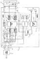
図1に、本実施形態にかかる移動体通信端末の構成を示す。この移動体通信端末は、本体0、充電部1、制御部2及び無線部3を有する。
[First Embodiment]
A first embodiment in which the present invention is suitably implemented will be described.
FIG. 1 shows a configuration of a mobile communication terminal according to the present embodiment. This mobile communication terminal includes a
充電部1は、充電電流検出用抵抗部12、充電電流検出回路8、外部電圧検出回路9、出力制御スイッチ7、電池温度検出回路11、電池電圧検出回路10及び充電制御回路6を有する。
充電電流検出用抵抗部12は、充電端子21に接続されている。充電電流検出回路8は、充電電流検出用抵抗部12の両端に接続されており、充電電流検出用抵抗部12における電圧降下量に基づいて、充電電流検出用抵抗部12を流れる電流値が所定の閾値以上であるか否かを検出する。外部電圧検出回路9は、充電端子21に接続されている。出力制御スイッチ7は、充電電流検出用抵抗部12に接続されており、充電部1の出力を制御する。電池電圧検出回路10は、充電部1の出力端子に接続されており、電池パック4の電池電圧を検出する。電池温度検出回路11は、電池端子22を介して電池パック4内の温度検出器20に接続されており、電池パック4の温度を検出する。充電制御回路6は、充電電流検出回路8、外部電圧検出回路9、電池電圧検出回路10、出力制御スイッチ7、電池温度検出回路11に接続され、それぞれの検出回路で検出した結果により出力制御スイッチ7の状態を制御する。
The
The charging current detecting resistor 12 is connected to the
充電部1の出力は、制御部2及び無線部3へ電源として供給されるとともに、電池端子22を介して電池パック4へも供給される。
充電電流検出用抵抗部12は、抵抗24と、これに直列に接続されたスイッチ25と、抵抗24及びスイッチ25に並列に接続された抵抗23とから構成される。スイッチ25は、無線部3が通信状態にある場合にはOFF、停止状態(非通信状態)にある場合にはONとなるようにCPU13によって制御される。
The output of the
The charging current detection resistor unit 12 includes a resistor 24, a
制御部2は、表示部14、操作部15、音声処理回路16及びCPU13を有する。表示部14は、ユーザに情報を視覚的に提示するための機能部である。操作部15は、ユーザが移動体通信端末を操作するためのインタフェースである。音声処理回路16は、無線部3、スピーカ17及びマイク18に接続されており、音声信号の変調や復調を行う。CPU13は、表示部14、操作部15、音声処理回路16、無線部3、充電制御回路6及びスイッチ25にそれぞれ接続されており、各部の状態検出や制御を行う。
The
電池パック4は、電池セル19及び温度検出器20を有する。電池セル19は、電荷を蓄積・放出するための部材である。温度検出器20は、電池パック4の温度を検出する。
The
外部給電器5は、本体0の外部に露出した充電端子21を介して充電部1に接続され、商用電源や車載電源から供給される電流を、安定した直流電源に変換して充電部1に供給する。
The
図5に、携帯電話端末の外観を示す。本体0は、上側筐体28及び下側筐体27とで構成されており、上側筐体28は表示部14及びスピーカ17を、下側筐体27は操作部15、マイク18及び充電端子21を備えている。
FIG. 5 shows the appearance of the mobile phone terminal. The
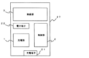
図6に、下側筐体27の内部構成例を示す。下側筐体27の内部には、無線部3、制御部2、充電部1、電池端子22が配置される。
FIG. 6 shows an internal configuration example of the
携帯電話端末の充電中の動作について説明する。
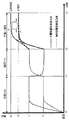
図7に、本実施形態にかかる携帯電話端末の筐体表面温度の変化を示す。なお、比較のため、従来構成の携帯電話端末の筐体表面温度の変化も合わせて示す。初期状態(時刻t0)においては、携帯電話端末の筐体表面の温度は室温と同じとする。
An operation during charging of the mobile phone terminal will be described.
FIG. 7 shows changes in the housing surface temperature of the mobile phone terminal according to the present embodiment. For comparison, the change in the surface temperature of the casing of the mobile phone terminal having the conventional configuration is also shown. In the initial state (time t0), the temperature of the housing surface of the mobile phone terminal is the same as the room temperature.
時刻t0からt1の期間は、電池パック4の充電のみが行われている。電池パック4の充電のみを行う状態では、外部給電器5は充電端子21に接続されており、充電部1によって電池パック4が充電される。この時、無線部3は停止状態(非通信状態)であり、スイッチ25は、CPU13によってオンに制御されている。
電池パック4の充電が開始されると、充電部1が発する熱が筐体に伝わって、充電部1付近の筐体表面温度はk2に達し、無線部3付近の筐体表面温度はk1に達する。
Only the
When charging of the
時刻t1からt2までの期間は、通話のみが行われている。通話のみを行う状態では、外部給電器5は充電端子21に接続されておらず、充電部1は停止状態となっている。また、無線部3は通信状態にあり、スイッチ25はCPU13によってオフに制御されている。
この状態では、通信状態にある無線部3の発熱によって、下側筐体27の無線部3付近の温度はk2に達する。また、充電部1付近の筐体表面温度は、電池パック4を充電している時よりは低くなるものの、無線部3から熱が伝わるために室温までは低下せず、温度k1で定常状態となる。
Only a call is made during the period from time t1 to t2. In a state where only a call is performed, the
In this state, the temperature near the
時刻t2からt3の期間は、電池パック4の充電と通話とが同時に行われている。電池パック4の充電と通話とを同時に行う場合には、外部給電器5は充電端子21に接続され、無線部3は通信状態となる。また、スイッチ25はCPU13によってオフに制御される。
この状態においては、下側筐体27の充電部1付近及び無線部3付近の表面温度は、相互の熱伝導によって煽られるため、充電部1や無線部3が単独で動作する時よりも高くなる。
During the period from time t2 to t3, charging of the
In this state, the surface temperatures of the
筐体表面温度は、熱源の発熱量と、熱源から筐体表面までの熱抵抗で定まるが、充電部1の主たる発熱源は、充電用電流検出用抵抗部12と出力制御スイッチ7である(熱抵抗の定義は本発明の主旨とは直接は関係しないので、説明は割愛する)。無線部3の熱源は、送信部にあり、発熱量は主にその出力電力によって定まる。
The case surface temperature is determined by the amount of heat generated by the heat source and the thermal resistance from the heat source to the case surface, and the main heat source of the charging
充電電流検出用抵抗部12に充電電流が流れると、充電電流検出回路8では充電電流検出用抵抗部12での電圧降下量が所定の閾値以上として検出される。充電制御回路6は、この電圧降下量が一定となるように出力制御スイッチ7を制御する。すなわち、充電制御回路6は、充電電流を所定電流(Ichg)に制御している。なお、Ichgは、電池パック4の容量がC[mAh]であるならば、C[mA]程度とすることが一般的である。
When a charging current flows through the charging current detection resistor 12, the charging
充電電流検出用抵抗部12の抵抗値をRchg[Ω]、外部給電器5の出力電圧をVchg[V]、電池パック4の電圧(=充電部1の出力電圧)をVbatt[V]とすると、充電電流検出用抵抗部12の発熱量は、
Rchg×Ichg 2[W]・・・(1)
出力制御スイッチ7の発熱量は、
(Vchg−Rchg×Ichg−Vbatt)×Ichg
≒(Vchg−Vbatt)×Ichg[W]・・・(2)
となる。
The resistance value of the charging current detection resistor 12 is R chg [Ω], the output voltage of the
R chg × I chg 2 [W] (1)
The amount of heat generated by the
(V chg −R chg × I chg −V batt ) × I chg
≒ (V chg -V batt ) x I chg [W] (2)
It becomes.
式(1)、(2)から明らかなように、充電電流検出用抵抗部12の発熱量及び出力制御スイッチ7の発熱量はいずれもIchgが増加すると大きくなるため、充電電流(Ichg)を制御すれば発熱量を制御できる。
As is apparent from the equations (1) and (2), the amount of heat generated by the charging current detection resistor 12 and the amount of heat generated by the
図8に、従来の携帯電話端末の構成を示す。従来の携帯電話端末は、本実施形態にかかる携帯電話端末とは充電電流検出部抵抗部12の構成が異なっており、抵抗29のみで構成されている。すなわち、従来構成の携帯電話端末は、端末の状態に関わらず充電電流(Ichg)は所定値C[mA]である。
FIG. 8 shows a configuration of a conventional mobile phone terminal. The conventional mobile phone terminal is different from the mobile phone terminal according to the present embodiment in the configuration of the charging current detection unit resistance unit 12, and is configured only by the
一方、本実施形態にかかる携帯電話端末においては、無線部3の通信状態(通信状態にあるか否か)に応じて、充電電流検出用抵抗部12のスイッチ25をCPU13が切り替える。スイッチ25がオン(通電状態)のときは、抵抗23及び抵抗24の合成抵抗値が従来構成の携帯電話端末の抵抗29と同じ値となり、充電電流(Ichg)はC[mA]となる。
On the other hand, in the mobile phone terminal according to the present embodiment, the CPU 13 switches the
ここで、抵抗23の抵抗値をR1[Ω]、抵抗24の抵抗値をR2[Ω]、抵抗25の抵抗値をR3[Ω]とし、説明の簡略化のためにR1=R2とすると、スイッチ25がオンの時の充電電流検出用抵抗部12の抵抗値Rchg1は、
Rchg1=R1×R2/(R1+R2)=(1/2)×R1=R3[Ω]・・・(3)
となる。
Here, assuming that the resistance value of the
R chg1 = R1 × R2 / (R1 + R2) = (1/2) × R1 = R3 [Ω] (3)
It becomes.
また、スイッチ25がオフ(絶縁状態)となると、充電電流(Ichg)は抵抗23のみを流れる。すなわち、この時の充電電流検出用抵抗部12の抵抗値Rchg2は、
Rchg2=R1=2×R3[Ω]・・・(4)
となる。
When the
R chg2 = R1 = 2 × R3 [Ω] (4)
It becomes.
先に説明したように、本実施形態にかかる携帯電話端末は、充電電流検出回路8が充電電流検出用抵抗部12の電圧降下量を検出し、電圧降下量が一定となるように充電制御回路6が出力制御スイッチ7を制御する。このため、スイッチ25がオフの時の充電電流をIchg2とすると、
Rchg1×Ichg1=Rchg2×Ichg2
(1/2)×R1×C=R1×Ichg2
Ichg2=1/2×C・・・(5)
となり、充電電流がスイッチ25がオンの時の1/2となる。
As described above, in the mobile phone terminal according to the present embodiment, the
R chg1 × I chg1 = R chg2 × I chg2
(1/2) × R1 × C = R1 × I chg2
I chg2 = 1/2 × C (5)
Thus, the charging current is ½ that when the
よって、式(1)〜(5)から、スイッチ25がオフの時、充電電流検出用抵抗部12及び出力制御スイッチ7の発熱量は、スイッチ25がオンの時の1/2となる。
Therefore, from the formulas (1) to (5), when the
図7の時刻t2からt3の期間では下側筐体27の表面温度は、従来の携帯電話端末(図7中に“G”で示す。)と比較して、本実施形態にかかる携帯電話端末(図7中に“F”で示す。)の方が低くなっており、筐体表面温度の上昇が抑制されている。
In the period from time t2 to time t3 in FIG. 7, the surface temperature of the
なお、上記の説明においては説明の簡略化のために抵抗23の抵抗値R1と抵抗24の抵抗値R2とが等しい(R1=R2)としたが、この条件に限定されることはなく、充電電流検出用抵抗部12の抵抗値がR1とR2との合成抵抗値であるときに充電電流IchgがC[mA]となるようにし、充電電流検出用抵抗部12の抵抗値がR1である場合に通話時の最大消費電流を補える程度の充電電流値に設定すればよい。
In the above description, the resistance value R1 of the
このように、本実施形態にかかる携帯電話端末は、充電中には無線部3の動作状態に応じてCPU13が充電電流検出用抵抗部12のスイッチを切り替えて(無線部3が通信状態ならばスイッチ25をオン、停止状態ならばスイッチ25をオフ)、充電部1での発熱量を低減させる。これにより、携帯電話端末の筐体表面の温度上昇を抑制できる。
なお、上記構成において、充電電流の制御は全て携帯電話端末内で行われるため、外部給電器5側に特別な構成を必要としない。すなわち、電池パック4の定格に適合するものを用いる必要はあるものの、外部給電器5としては一般的な充電器を用いることができる。
Thus, in the mobile phone terminal according to the present embodiment, during charging, the CPU 13 switches the switch of the charging current detection resistor 12 according to the operating state of the wireless unit 3 (if the
In the above configuration, since the charging current is all controlled in the mobile phone terminal, no special configuration is required on the
本実施形態によれば、筐体表面の温度上昇を抑制し、充電中でもユーザが安全に使用できる携帯電話端末を提供できる。 According to the present embodiment, it is possible to provide a mobile phone terminal that can suppress a temperature rise on the surface of the housing and can be used safely by the user even during charging.
〔第2の実施形態〕
本発明を好適に実施した第2の実施形態について説明する。
図2に、本実施形態にかかる携帯電話端末の構成を示す。本実施形態にかかる携帯電話端末は、第1の実施形態にかかる携帯電話端末とほぼ同様の構成である。ただし、本実施形態においては、充電電流検出用抵抗部12は、抵抗23のみで構成される。
[Second Embodiment]
A second embodiment in which the present invention is suitably implemented will be described.
FIG. 2 shows a configuration of the mobile phone terminal according to the present embodiment. The mobile phone terminal according to the present embodiment has substantially the same configuration as the mobile phone terminal according to the first embodiment. However, in the present embodiment, the charging current detection resistor unit 12 is configured by only the
充電電流検出回路8は、第1の実施形態では充電電流検出用抵抗部12での電圧降下量が閾値以上であるか否かを検出していたが、本実施形態では閾値を複数有しており、電圧降下量がどの範囲にあるかを検出している。
In the first embodiment, the charging
充電制御回路6は、抵抗値検出用抵抗部12での電圧降下量がどの範囲にあるかを充電電流検出回路8から通知されると出力制御スイッチ7を制御し、電圧降下量に応じた電流値となるように充電電流の電流値を制御する。
The charging
本実施形態における動作は、充電電流抵抗用検出部12のスイッチ25のオン・オフ制御を充電電流検出回路8の閾値に置き換えたものであり、これ以外については上記第1の実施形態と同様であるため、重複する説明は省略する。
The operation in this embodiment is the same as that in the first embodiment except that the on / off control of the
〔第3の実施形態〕
本発明を好適に実施した第3の実施形態について説明する。
第1の実施形態にかかる携帯電話端末は、電池パック4を充電中で無線部3が通信状態にある場合には、常に充電電流を小さくして、筐体表面温度の上昇を抑制していた。しかし、電池パック4を充電中かつ無線部3が通信状態にある場合でも、筐体表面温度が高くなければ、充電電流を小さくする必要はない。よって、電池パックを充電中かつ通信状態にある場合に常に充電電流を小さくしてしまうと、電池パック4の充電に要する時間が必要以上に長くなってしまう。
[Third Embodiment]
A third embodiment in which the present invention is preferably implemented will be described.
In the mobile phone terminal according to the first embodiment, when the
よって、本実施形態においては、筐体表面の温度に応じて充電電流の大きさを変更する携帯電話端末について説明する。 Therefore, in the present embodiment, a mobile phone terminal that changes the magnitude of the charging current according to the temperature of the housing surface will be described.
図3に、本実施形態にかかる携帯電話端末の構成を示す。本実施形態にかかる携帯電話端末は第1の実施形態とほぼ同様の構成であり、充電部1、制御部2及び無線部3を有する。ただし、本実施形態において携帯電話端末は温度センサ26をさらに備えている。
温度センサ26は、筐体表面の温度を測定するセンサである。温度センサ26は任意の位置に配置可能であるが、無線部3の近傍に配置することが好ましい。
FIG. 3 shows the configuration of the mobile phone terminal according to the present embodiment. The mobile phone terminal according to the present embodiment has substantially the same configuration as that of the first embodiment, and includes a
The
本実施形態にかかる携帯電話端末の動作について説明する。
本実施形態にかかる携帯電話端末の動作は第1の実施形態とほぼ同様であるが、CPU13は温度センサ26から通知される温度が閾値未満のときは、充電中かつ通信状態であっても充電電流を切り替えず、充電中かつ通信状態でありさらに温度センサ26から通知される温度が閾値以上となとなったときに出力制御スイッチ7を制御して充電電流を切り替える。
The operation of the mobile phone terminal according to the present embodiment will be described.
The operation of the mobile phone terminal according to the present embodiment is almost the same as that of the first embodiment. However, when the temperature notified from the
無線部3の熱源は送信部であり、その出力電力は無線部3での受信状態に応じてCPU13によってパワーダウン制御される(他の局からの無線信号を無線部3での良好に受信できているのであれば、発信する無線信号も低出力で良いため。)のが一般的である。無線部3の発熱量は主にこのパワーダウン制御によって定まるため、送信部の出力電力がパワーダウンされれば、発熱量も小さくなる。すなわち、無線部3が低出力で動作している場合(弱い無線信号を送出している場合)には、通信状態であっても無線部3の発熱による筐体温度の上昇は小さい。
The heat source of the
本実施形態にかかる携帯電話端末は、充電中かつ通信状態にある場合でも、筐体の温度が所定の温度未満であれば、充電電流を小さくしないため、無線部3が低出力で動作している場合には充電時間が長くはならない。
Even when the mobile phone terminal according to the present embodiment is being charged and in a communication state, if the temperature of the casing is lower than a predetermined temperature, the
このように、本実施形態にかかる携帯電話端末は、低出力で通信中の充電を効率的に行える。 Thus, the mobile phone terminal according to the present embodiment can efficiently perform charging during communication with low output.
〔第4の実施形態〕
本発明を好適に実施した第4の実施形態について説明する。図4に本実施形態にかかる携帯電話端末の構成を示す。
本実施形態にかかる携帯電話端末において、充電電流検出用抵抗部12は、抵抗24とスイッチ25との組に加え、スイッチ31と抵抗30との組を備えている。これにより、本実施形態においてCPU13は、充電電流検出用抵抗部12の合成抵抗値を2bitの値として制御する。
[Fourth Embodiment]
A fourth embodiment in which the present invention is preferably implemented will be described. FIG. 4 shows the configuration of the mobile phone terminal according to the present embodiment.
In the mobile phone terminal according to the present embodiment, the charging current detecting resistor 12 includes a pair of a switch 31 and a resistor 30 in addition to a pair of a resistor 24 and a
第3の実施形態において説明したように、無線部3の送信部の出力電力はCPU13によって数段階に制御される。出力電力が低下すれば無線部3の発熱量も低下するため、送信部の出力電力に応じて充電電流を切り替えれば、通話中の充電を安全かつ効率的に制御できる。
As described in the third embodiment, the output power of the transmission unit of the
ここでは、CPU13が充電電流検出用抵抗部12の合成抵抗を2bitの値として制御する場合を例に説明したが、スイッチと抵抗との組をさらに増やして合成抵抗を3bit以上の値として制御しても良い。 Here, the case where the CPU 13 controls the combined resistance of the charging current detection resistor unit 12 as a 2-bit value has been described as an example. However, the combination of switches and resistors is further increased to control the combined resistance as a value of 3 bits or more. May be.
なお、上記各実施形態は本発明の好適な実施の一例であり、本発明はこれに限定されることはない。
例えば、上記各実施形態においては、携帯型電子機器の例として携帯電話端末を上げているが、本発明は携帯電話端末以外の携帯型電子機器にも適用可能であり、上記各実施形態で例示した折り畳み型の端末構成に限定されることもない。
また、上記各実施形態では、通信部が発熱源となる場合を例に説明したが、発熱源はこれ以外の電子デバイスであっても構わない。カメラやスピーカ着信など大きく電力を消費する機能も増えており、これらの機能を実現する電子デバイスにおける発熱量も増加している。よって、上記各実施形態において発熱源として例示した無線部の代わりに撮像素子などの動作状態に応じて充電電流を切り替えることでも筐体表面の温度上昇を抑制できる。
このように、本発明は様々な変形が可能である。
Each of the above embodiments is an example of a preferred embodiment of the present invention, and the present invention is not limited to this.
For example, in each of the above embodiments, a mobile phone terminal is given as an example of the portable electronic device. However, the present invention can also be applied to a portable electronic device other than the mobile phone terminal, and is exemplified in each of the above embodiments. It is not limited to the foldable terminal configuration.
In each of the above embodiments, the case where the communication unit is a heat source has been described as an example. However, the heat source may be an electronic device other than this. Functions that consume a large amount of power, such as cameras and speaker calls, are increasing, and the amount of heat generated in electronic devices that realize these functions is also increasing. Therefore, the temperature rise on the surface of the housing can be suppressed by switching the charging current according to the operation state of the imaging element or the like instead of the wireless unit exemplified as the heat generation source in each of the above embodiments.
As described above, the present invention can be variously modified.
1 充電部
2 制御部
3 無線部
4 電池パック
5 外部給電器
6 充電制御回路
7 出力制御スイッチ
8 充電電流検出回路
9 外部電圧検出回路
10 電池電圧検出回路
11 電池温度検出回路
12 充電電流検出用抵抗部
13 CPU
14 表示部
15 操作部
16 音声処理回路
17 スピーカ
18 マイク
19 セル
20 温度検知器
21 充電端子
22 電池端子
23、24b、30 抵抗
25、31 スイッチ
26 温度センサ
27 下側筐体
28 上側筐体
DESCRIPTION OF
DESCRIPTION OF
Claims (8)
前記蓄電池を充電する際に前記発熱源のいずれかが作動している場合には、前記蓄電池を充電するための充電電流の電流値を前記発熱源がいずれも作動していない場合よりも小さくすることを特徴とする携帯型電子機器。 It has at least one electronic device to be a heat source, can be operated using the attached storage battery as a power source, and when connected to an external power supply with the storage battery attached, supplied from the external power supply A portable electronic device that charges the storage battery with a current that is
When any of the heat sources is operating when charging the storage battery, the current value of the charging current for charging the storage battery is made smaller than when none of the heat sources is operating. A portable electronic device characterized by that.
該抵抗部の抵抗値は少なくとも二つのいずれかに可変可能であり、該抵抗部における電圧降下に応じて前記充電電流の電流値を変化させることを特徴とする請求項1記載の携帯型電子機器。 A resistor for detecting a current supplied from the external power supply;
2. The portable electronic device according to claim 1, wherein the resistance value of the resistance portion can be changed to at least two, and the current value of the charging current is changed according to a voltage drop in the resistance portion. .
通信状態にあるときに、前記蓄電池を充電するための充電電流の電流値を非通信状態にあるときよりも小さくすることを特徴とする移動体通信端末。 A mobile communication terminal that can operate using a mounted storage battery as a power source and charges the storage battery with a current supplied from the external power supply when the storage battery is connected to an external power supply Because
A mobile communication terminal characterized in that, when in a communication state, a current value of a charging current for charging the storage battery is made smaller than that in a non-communication state.
該抵抗部の抵抗値は少なくとも二つの値のいずれかに可変可能であり、該抵抗部における電圧降下に応じて前記充電電流の電流値を変化させることを特徴とする請求項5記載の移動体通信端末。 A resistor for detecting a current supplied from the external power supply;
6. The moving body according to claim 5, wherein the resistance value of the resistance portion is variable to at least two values, and the current value of the charging current is changed according to a voltage drop in the resistance portion. Communication terminal.
Priority Applications (1)
| Application Number | Priority Date | Filing Date | Title |
|---|---|---|---|
| JP2005085623A JP4463131B2 (en) | 2004-04-22 | 2005-03-24 | Portable electronic device and mobile communication terminal |
Applications Claiming Priority (2)
| Application Number | Priority Date | Filing Date | Title |
|---|---|---|---|
| JP2004126399 | 2004-04-22 | ||
| JP2005085623A JP4463131B2 (en) | 2004-04-22 | 2005-03-24 | Portable electronic device and mobile communication terminal |
Publications (2)
| Publication Number | Publication Date |
|---|---|
| JP2005333794A true JP2005333794A (en) | 2005-12-02 |
| JP4463131B2 JP4463131B2 (en) | 2010-05-12 |
Family
ID=35488033
Family Applications (1)
| Application Number | Title | Priority Date | Filing Date |
|---|---|---|---|
| JP2005085623A Expired - Fee Related JP4463131B2 (en) | 2004-04-22 | 2005-03-24 | Portable electronic device and mobile communication terminal |
Country Status (1)
| Country | Link |
|---|---|
| JP (1) | JP4463131B2 (en) |
Cited By (8)
| Publication number | Priority date | Publication date | Assignee | Title |
|---|---|---|---|---|
| JP2007166500A (en) * | 2005-12-16 | 2007-06-28 | Nec Corp | Mobile phone and control method of mobile phone |
| JP2007300738A (en) * | 2006-04-28 | 2007-11-15 | Nec Saitama Ltd | Electronic equipment having secondary battery, and charge control method |
| JP2008278570A (en) * | 2007-04-26 | 2008-11-13 | Kyocera Corp | Portable terminal, and charging method |
| JP2010035384A (en) * | 2008-07-31 | 2010-02-12 | Denso Wave Inc | Portable information terminal |
| US8169189B2 (en) | 2005-01-18 | 2012-05-01 | Nec Corporation | Mobile terminal with a temperature sensor and method of charging battery mounted in mobile terminal |
| JP2013027153A (en) * | 2011-07-21 | 2013-02-04 | Kyocera Corp | Communication terminal, charge control program, and charge control method |
| JP2016067104A (en) * | 2014-09-24 | 2016-04-28 | レノボ・シンガポール・プライベート・リミテッド | Portable information processing unit, battery control method thereof, and computer executable program |
| JP2017108542A (en) * | 2015-12-10 | 2017-06-15 | 京セラ株式会社 | Electronic apparatus, controller, control program, and charging current control method |
-
2005
- 2005-03-24 JP JP2005085623A patent/JP4463131B2/en not_active Expired - Fee Related
Cited By (11)
| Publication number | Priority date | Publication date | Assignee | Title |
|---|---|---|---|---|
| US8169189B2 (en) | 2005-01-18 | 2012-05-01 | Nec Corporation | Mobile terminal with a temperature sensor and method of charging battery mounted in mobile terminal |
| JP2007166500A (en) * | 2005-12-16 | 2007-06-28 | Nec Corp | Mobile phone and control method of mobile phone |
| JP4635858B2 (en) * | 2005-12-16 | 2011-02-23 | 日本電気株式会社 | Mobile phone and mobile phone control method |
| JP2007300738A (en) * | 2006-04-28 | 2007-11-15 | Nec Saitama Ltd | Electronic equipment having secondary battery, and charge control method |
| JP4650332B2 (en) * | 2006-04-28 | 2011-03-16 | 日本電気株式会社 | Electronic device having secondary battery and charge control method |
| JP2008278570A (en) * | 2007-04-26 | 2008-11-13 | Kyocera Corp | Portable terminal, and charging method |
| JP2010035384A (en) * | 2008-07-31 | 2010-02-12 | Denso Wave Inc | Portable information terminal |
| JP2013027153A (en) * | 2011-07-21 | 2013-02-04 | Kyocera Corp | Communication terminal, charge control program, and charge control method |
| US9252607B2 (en) | 2011-07-21 | 2016-02-02 | Kyocera Corporation | Communication terminal, charge control program and charge control method |
| JP2016067104A (en) * | 2014-09-24 | 2016-04-28 | レノボ・シンガポール・プライベート・リミテッド | Portable information processing unit, battery control method thereof, and computer executable program |
| JP2017108542A (en) * | 2015-12-10 | 2017-06-15 | 京セラ株式会社 | Electronic apparatus, controller, control program, and charging current control method |
Also Published As
| Publication number | Publication date |
|---|---|
| JP4463131B2 (en) | 2010-05-12 |
Similar Documents
| Publication | Publication Date | Title |
|---|---|---|
| US7541779B2 (en) | Portable electronic device and mobile communication terminal | |
| JP4463131B2 (en) | Portable electronic device and mobile communication terminal | |
| US6043626A (en) | Auxiliary battery holder with multicharger functionality | |
| JP3807556B2 (en) | Auxiliary battery sensor switch | |
| US8237410B2 (en) | Handheld device with fast-charging capability | |
| US5717314A (en) | Apparatus and method of monitoring battery temperature during charging | |
| US20080074084A1 (en) | Electronic device and method for controlling charging current | |
| JP2005512355A (en) | Power charging PAN architecture | |
| EP1096638A1 (en) | Electronic device and method of controlling electronic devices | |
| JP3526028B2 (en) | Power supply circuit, power supply circuit control method, and electronic device using this power supply circuit | |
| US9252607B2 (en) | Communication terminal, charge control program and charge control method | |
| JP5876217B2 (en) | Mobile terminal device | |
| US7248902B2 (en) | Multi-mode power supply device of wireless earphone | |
| JP4650332B2 (en) | Electronic device having secondary battery and charge control method | |
| JP2005295683A (en) | Portable terminal apparatus | |
| JP2008113528A (en) | Power supply circuit, power supply control method, electronic equipment equipped with the power supply circuit, and operating state monitoring control program | |
| JP5224975B2 (en) | Mobile station | |
| CN113607297A (en) | Temperature detection circuit and earphone | |
| KR20040026724A (en) | Charging apparatus of mobile terminal | |
| JP5557322B2 (en) | Charging stand | |
| CN215296490U (en) | Temperature detection circuit and earphone | |
| KR100627734B1 (en) | Method and Apparatus for Supplying Emergency Power for Use with Portable Device | |
| JP2009207347A (en) | Portable electronic device, charger, charging method, and charging system | |
| JP2604550Y2 (en) | Charging device | |
| JP2008054429A (en) | Charge circuit and electronic equipment |
Legal Events
| Date | Code | Title | Description |
|---|---|---|---|
| A621 | Written request for application examination |
Free format text: JAPANESE INTERMEDIATE CODE: A621 Effective date: 20080215 |
|
| A977 | Report on retrieval |
Free format text: JAPANESE INTERMEDIATE CODE: A971007 Effective date: 20081127 |
|
| A131 | Notification of reasons for refusal |
Free format text: JAPANESE INTERMEDIATE CODE: A131 Effective date: 20081209 |
|
| A521 | Written amendment |
Free format text: JAPANESE INTERMEDIATE CODE: A523 Effective date: 20090202 |
|
| TRDD | Decision of grant or rejection written | ||
| A01 | Written decision to grant a patent or to grant a registration (utility model) |
Free format text: JAPANESE INTERMEDIATE CODE: A01 Effective date: 20100126 |
|
| A01 | Written decision to grant a patent or to grant a registration (utility model) |
Free format text: JAPANESE INTERMEDIATE CODE: A01 |
|
| A61 | First payment of annual fees (during grant procedure) |
Free format text: JAPANESE INTERMEDIATE CODE: A61 Effective date: 20100216 |
|
| FPAY | Renewal fee payment (event date is renewal date of database) |
Free format text: PAYMENT UNTIL: 20130226 Year of fee payment: 3 |
|
| R150 | Certificate of patent or registration of utility model |
Free format text: JAPANESE INTERMEDIATE CODE: R150 |
|
| FPAY | Renewal fee payment (event date is renewal date of database) |
Free format text: PAYMENT UNTIL: 20130226 Year of fee payment: 3 |
|
| S111 | Request for change of ownership or part of ownership |
Free format text: JAPANESE INTERMEDIATE CODE: R313113 |
|
| FPAY | Renewal fee payment (event date is renewal date of database) |
Free format text: PAYMENT UNTIL: 20130226 Year of fee payment: 3 |
|
| R350 | Written notification of registration of transfer |
Free format text: JAPANESE INTERMEDIATE CODE: R350 |
|
| FPAY | Renewal fee payment (event date is renewal date of database) |
Free format text: PAYMENT UNTIL: 20130226 Year of fee payment: 3 |
|
| FPAY | Renewal fee payment (event date is renewal date of database) |
Free format text: PAYMENT UNTIL: 20140226 Year of fee payment: 4 |
|
| S111 | Request for change of ownership or part of ownership |
Free format text: JAPANESE INTERMEDIATE CODE: R313113 |
|
| R350 | Written notification of registration of transfer |
Free format text: JAPANESE INTERMEDIATE CODE: R350 |
|
| R250 | Receipt of annual fees |
Free format text: JAPANESE INTERMEDIATE CODE: R250 |
|
| R250 | Receipt of annual fees |
Free format text: JAPANESE INTERMEDIATE CODE: R250 |
|
| LAPS | Cancellation because of no payment of annual fees |