JP4635597B2 - Electronics and batteries - Google Patents
Electronics and batteries Download PDFInfo
- Publication number
- JP4635597B2 JP4635597B2 JP2004365645A JP2004365645A JP4635597B2 JP 4635597 B2 JP4635597 B2 JP 4635597B2 JP 2004365645 A JP2004365645 A JP 2004365645A JP 2004365645 A JP2004365645 A JP 2004365645A JP 4635597 B2 JP4635597 B2 JP 4635597B2
- Authority
- JP
- Japan
- Prior art keywords
- battery
- electronic device
- case
- connector portion
- locking
- Prior art date
- Legal status (The legal status is an assumption and is not a legal conclusion. Google has not performed a legal analysis and makes no representation as to the accuracy of the status listed.)
- Expired - Fee Related
Links
- 238000003780 insertion Methods 0.000 claims description 14
- 230000037431 insertion Effects 0.000 claims description 14
- 238000001514 detection method Methods 0.000 claims description 5
- 238000003384 imaging method Methods 0.000 description 40
- 230000004308 accommodation Effects 0.000 description 7
- 238000012545 processing Methods 0.000 description 7
- 238000010586 diagram Methods 0.000 description 6
- 230000003287 optical effect Effects 0.000 description 6
- 238000013461 design Methods 0.000 description 2
- 230000000694 effects Effects 0.000 description 2
- 229910000639 Spring steel Inorganic materials 0.000 description 1
- 238000013459 approach Methods 0.000 description 1
- 238000004891 communication Methods 0.000 description 1
- 239000011810 insulating material Substances 0.000 description 1
- 230000009191 jumping Effects 0.000 description 1
- 230000003014 reinforcing effect Effects 0.000 description 1
- 229920003002 synthetic resin Polymers 0.000 description 1
- 239000000057 synthetic resin Substances 0.000 description 1
Images


Classifications
-
- H—ELECTRICITY
- H01—ELECTRIC ELEMENTS
- H01M—PROCESSES OR MEANS, e.g. BATTERIES, FOR THE DIRECT CONVERSION OF CHEMICAL ENERGY INTO ELECTRICAL ENERGY
- H01M50/00—Constructional details or processes of manufacture of the non-active parts of electrochemical cells other than fuel cells, e.g. hybrid cells
- H01M50/20—Mountings; Secondary casings or frames; Racks, modules or packs; Suspension devices; Shock absorbers; Transport or carrying devices; Holders
- H01M50/202—Casings or frames around the primary casing of a single cell or a single battery
-
- H—ELECTRICITY
- H01—ELECTRIC ELEMENTS
- H01M—PROCESSES OR MEANS, e.g. BATTERIES, FOR THE DIRECT CONVERSION OF CHEMICAL ENERGY INTO ELECTRICAL ENERGY
- H01M50/00—Constructional details or processes of manufacture of the non-active parts of electrochemical cells other than fuel cells, e.g. hybrid cells
- H01M50/10—Primary casings, jackets or wrappings of a single cell or a single battery
- H01M50/102—Primary casings, jackets or wrappings of a single cell or a single battery characterised by their shape or physical structure
- H01M50/103—Primary casings, jackets or wrappings of a single cell or a single battery characterised by their shape or physical structure prismatic or rectangular
-
- H—ELECTRICITY
- H01—ELECTRIC ELEMENTS
- H01M—PROCESSES OR MEANS, e.g. BATTERIES, FOR THE DIRECT CONVERSION OF CHEMICAL ENERGY INTO ELECTRICAL ENERGY
- H01M50/00—Constructional details or processes of manufacture of the non-active parts of electrochemical cells other than fuel cells, e.g. hybrid cells
- H01M50/20—Mountings; Secondary casings or frames; Racks, modules or packs; Suspension devices; Shock absorbers; Transport or carrying devices; Holders
- H01M50/244—Secondary casings; Racks; Suspension devices; Carrying devices; Holders characterised by their mounting method
-
- H—ELECTRICITY
- H01—ELECTRIC ELEMENTS
- H01M—PROCESSES OR MEANS, e.g. BATTERIES, FOR THE DIRECT CONVERSION OF CHEMICAL ENERGY INTO ELECTRICAL ENERGY
- H01M50/00—Constructional details or processes of manufacture of the non-active parts of electrochemical cells other than fuel cells, e.g. hybrid cells
- H01M50/20—Mountings; Secondary casings or frames; Racks, modules or packs; Suspension devices; Shock absorbers; Transport or carrying devices; Holders
- H01M50/247—Mountings; Secondary casings or frames; Racks, modules or packs; Suspension devices; Shock absorbers; Transport or carrying devices; Holders specially adapted for portable devices, e.g. mobile phones, computers, hand tools or pacemakers
-
- H—ELECTRICITY
- H01—ELECTRIC ELEMENTS
- H01M—PROCESSES OR MEANS, e.g. BATTERIES, FOR THE DIRECT CONVERSION OF CHEMICAL ENERGY INTO ELECTRICAL ENERGY
- H01M50/00—Constructional details or processes of manufacture of the non-active parts of electrochemical cells other than fuel cells, e.g. hybrid cells
- H01M50/20—Mountings; Secondary casings or frames; Racks, modules or packs; Suspension devices; Shock absorbers; Transport or carrying devices; Holders
- H01M50/296—Mountings; Secondary casings or frames; Racks, modules or packs; Suspension devices; Shock absorbers; Transport or carrying devices; Holders characterised by terminals of battery packs
-
- Y—GENERAL TAGGING OF NEW TECHNOLOGICAL DEVELOPMENTS; GENERAL TAGGING OF CROSS-SECTIONAL TECHNOLOGIES SPANNING OVER SEVERAL SECTIONS OF THE IPC; TECHNICAL SUBJECTS COVERED BY FORMER USPC CROSS-REFERENCE ART COLLECTIONS [XRACs] AND DIGESTS
- Y02—TECHNOLOGIES OR APPLICATIONS FOR MITIGATION OR ADAPTATION AGAINST CLIMATE CHANGE
- Y02E—REDUCTION OF GREENHOUSE GAS [GHG] EMISSIONS, RELATED TO ENERGY GENERATION, TRANSMISSION OR DISTRIBUTION
- Y02E60/00—Enabling technologies; Technologies with a potential or indirect contribution to GHG emissions mitigation
- Y02E60/10—Energy storage using batteries
Description
本発明はバッテリーが装脱可能に装着される電子機器およびそのバッテリーに関する。 The present invention relates to an electronic device in which a battery is detachably mounted and the battery.
電子機器に装着されるバッテリーとして、前後方向の長さを有するケースと、ケースの内部に収容された電池セルと、ケースに設けられたコネクタ部とを備えたものがある(例えば特許文献1参照)。
このようなバッテリーが装着される電子機器は、電子機器に設けられたバッテリー収容室の開口からバッテリーがその長さ方向に沿って挿入されることでバッテリー側のコネクタ部がバッテリー収容室の電子機器側のコネクタ部に接続されるように構成されている。
An electronic device to which such a battery is attached is such that a battery is inserted along the length direction of the battery housing chamber from the opening of the battery housing chamber provided in the electronic device so that the connector portion on the battery side is the electronic device in the battery housing chamber. It is comprised so that it may be connected to the connector part of the side.
このような電子機器においては、多くの場合、バッテリーがバッテリー収容室に収容された状態でバッテリー収容室の開口を開閉蓋で閉塞し、その閉塞状態を係止することでバッテリーをバッテリー収容室内に保持している。
したがって、バッテリーをバッテリー収容室に挿入して開閉蓋を未だ閉塞していない状態ではバッテリーが保持されていないため、電子機器を傾けたり動かしたりすることに伴ってバッテリーがバッテリー収容室の外方に飛び出すなどしてバッテリー装脱操作の邪魔になるという不利があった。
本発明はこのような事情に鑑みなされたものであり、その目的は、バッテリーの装脱操作を円滑かつ確実に行う上で有利な電子機器およびバッテリーを提供することにある。
In such electronic devices, in many cases, the battery is accommodated in the battery accommodating chamber by closing the opening of the battery accommodating chamber with an opening / closing lid while the battery is accommodated in the battery accommodating chamber. keeping.
Therefore, since the battery is not held when the battery is inserted into the battery storage chamber and the opening / closing lid is not closed yet, the battery is moved to the outside of the battery storage chamber as the electronic device is tilted or moved. There was a disadvantage that it would interfere with the battery loading and unloading operation by jumping out.
The present invention has been made in view of such circumstances, and an object of the present invention is to provide an electronic device and a battery that are advantageous in smoothly and reliably performing a battery loading / unloading operation.
上述の目的を達成するため、本発明は、前面と、前面と対向する後面と、前面及び後面を接続し、且つケースの幅方向の両端に位置する2つの側面を有するバッテリーが装着されるバッテリー装着部が設けられた電子機器である。
バッテリー装着部は、バッテリーが挿入されるバッテリー収容室と、挿入方向におけるバッテリー収容室の奥部に設けられバッテリーの前面に設けられたコネクタ部が装着される電子機器側コネクタ部とを備えている。
そして、バッテリー収容室には、バッテリーの2つの側面から幅方向外方に突出する突出壁が係合される係合溝が挿入方向に沿って延在形成されており、係合溝の壁面には、バッテリーの突出壁に設けた係止用凹部に係止する係止部を有するばねが設けられている。
更に、ばねは、係止部が係止用凹部に係止することで、バッテリーを電子機器側コネクタ部方向に付勢することを特徴とする
また、本発明のバッテリーは、厚さ方向の両端に位置する上面および下面と、厚さよりも大きい寸法の幅方向の両端に位置し、互いに対向する2つの側面と、幅よりも大きい寸法の前後方向の両端に位置し、互いに対向する前面及び後面とを有する扁平な矩形板状のケースと、ケースの内部に収容された電池セルと、ケースの前面に設けられたコネクタ部とを備えている。
ケースの2つの側面には、幅方向外方に突出しつつ前後方向に延在する突出壁が設けられており、突出壁には、電子機器のバッテリー収容室における突出壁と係合する係合溝の壁面に設けられたばねの係止部と係止する係止用凹部が形成されている。そして、係止用凹部と前記ばねの係止部と係止することで、ケースが電子機器の電子機器側コネクタ部方向に付勢されることを特徴とする。
In order to achieve the above-described object, the present invention provides a battery to which a battery having a front surface, a rear surface facing the front surface, and two side surfaces connected to the front surface and the rear surface and positioned at both ends in the width direction of the case is mounted. Ru electronic devices der the mounting portion is provided.
The battery mounting portion includes a battery housing chamber into which the battery is inserted, and an electronic device-side connector portion that is provided at the back of the battery housing chamber in the insertion direction and to which a connector portion provided on the front surface of the battery is mounted . .
In the battery housing chamber, an engagement groove is formed extending along the insertion direction to be engaged with a protruding wall that protrudes outward in the width direction from the two side surfaces of the battery. Is provided with a spring having a locking portion that locks into a locking recess provided on the protruding wall of the battery.
Further, the spring is characterized in that the battery is urged toward the electronic device side connector part by the engaging part being engaged with the engaging concave part. The upper and lower surfaces are positioned at the opposite ends in the width direction with dimensions larger than the thickness , and are opposite to each other, and the front and rear surfaces are positioned at both ends in the front-rear direction with dimensions larger than the width and are opposed to each other. And a flat rectangular plate-shaped case, a battery cell accommodated in the case, and a connector portion provided on the front surface of the case .
The two side surfaces of the case are provided with projecting walls that project outward in the width direction and extend in the front-rear direction, and the projecting walls have engaging grooves that engage with the projecting walls in the battery housing chamber of the electronic device. A locking recess for locking with a spring locking portion provided on the wall surface is formed. The case is biased in the direction toward the electronic device side connector portion of the electronic device by engaging with the engaging recess and the engaging portion of the spring .
本発明の電子機器によれば、バッテリーを電子機器側コネクタ部方向に付勢するばねがバッテリー収容室に設けられているので、バッテリーはばねによってバッテリー収容室に収容された状態が保持される。
したがって、電子機器を傾けたり動かしたりしてもバッテリーの落下を防止できることは無論のこと、バッテリーは安定した状態でバッテリー収容室内に保持されているので、バッテリーの装脱操作を円滑かつ確実に行う上で有利となる。
また、本発明のバッテリーによれば、前記の電子機器に用いられることで、バッテリーのコネクタ部と電子機器側コネクタ部との装着状態が安定して保持され、バッテリーの電子機器への電源供給を安定して行う上で有利となる。
According to the electronic device of the present invention, since the spring for urging the battery in the direction toward the electronic device side connector is provided in the battery housing chamber, the battery is held in the battery housing chamber by the spring.
Therefore, it is of course possible to prevent the battery from falling even if the electronic device is tilted or moved. Since the battery is held in the battery housing chamber in a stable state, the battery can be inserted and removed smoothly and reliably. This is advantageous.
In addition, according to the battery of the present invention, by being used in the above-described electronic device, the mounting state of the connector portion of the battery and the connector portion of the electronic device is stably maintained, and power supply to the electronic device of the battery can be performed. This is advantageous for stable operation.
電子機器のバッテリー収容室に、前記電子機器側コネクタ部方向にバッテリーを付勢するばねを設けることによって上記目的を実現した。
バッテリーのケースの左右の側面にばねの係止用凹部を設けることによって上記目的を実現した。
The above object is achieved by providing a spring for energizing the battery in the direction of the electronic device side connector in the battery housing chamber of the electronic device.
The above-mentioned object is realized by providing recesses for latching springs on the left and right side surfaces of the battery case.
次に本発明の実施例1について図面を参照して説明する。
まず、本発明の電子機器に用いるバッテリーから説明する。
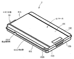
図1は実施例1で用いる第1のバッテリー2の斜視図、図2(A)は第1のバッテリー2の平面図、(B)は(A)のB矢視図、(C)は(A)のC矢視図、(D)は(A)のD矢視図、図3(E)は図2(D)のE矢視図、(F)は(E)のF矢視図である。
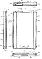
図4(A)は第1のバッテリー2を前方から見た正面図、(B)は(A)のB矢視図、(C)は(A)のC矢視図である。
図5は第1のバッテリー2の斜視図である。
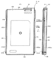
図6(A)は実施例1における第2のバッテリー4を前方から見た正面図、(B)は(A)のB矢視図、(C)は(A)のC矢視図である。
図7は第2のバッテリー4の斜視図である。
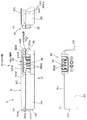
図8はバッテリーとばね60の説明図である。
なお、添付図面中、円筒面や曲面、傾斜面を表すために、部材や部分の表面に複数の直線や曲線を描いた図面も存在している。
Next, Embodiment 1 of the present invention will be described with reference to the drawings.
First, the battery used in the electronic device of the present invention will be described.
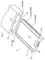
FIG. 1 is a perspective view of the
4A is a front view of the
FIG. 5 is a perspective view of the
6A is a front view of the
FIG. 7 is a perspective view of the
FIG. 8 is an explanatory diagram of the battery and the
In the accompanying drawings, there are also drawings in which a plurality of straight lines and curves are drawn on the surfaces of members and portions in order to represent cylindrical surfaces, curved surfaces, and inclined surfaces.
図1〜図5に示すように、第1のバッテリー2は電源が小容量のものであり、ケース10と、ケース10の内部に収容された不図示の電池セルと、ケース10に設けられたコネクタ部30とを備えている。
ケース10は、厚さ方向の両端に位置する上面10Cおよび下面10Dと、前記厚さよりも大きい寸法の幅方向の両端に位置する左右の側面10Eと、前記幅よりも大きい寸法の前後方向の両端に位置する前面10Aおよび後面10Bとを有する扁平な矩形板状に形成されている。なお、説明の便宜上、ケース10の左右方向はケース10の前方から見た状態でいうものとする。
2つの側面10Eには後述するばね60(図8)の係止用凹部1004が形成されている。
本実施例では、2つの側面10Eには、幅方向外方に突出しつつ長さ方向に延在する突出壁1002が設けられている。
係止用凹部1004は突出壁1002を切り欠くことで形成されている。
係止用凹部1004は左右の側面10Eの前後方向の中心よりも前面10A寄りの箇所に設けられている。
また、突出壁1002は、側面10Eの厚さ方向の中心に対して上面10Cまたは下面10D寄りの各側面10E箇所に設けられ、本実施例では、上面10C寄りの箇所に設けられている。したがって、バッテリーを上下逆転させて挿入しようとしても突出壁1002が係合溝54に挿入されず、したがってバッテリーの上下逆転による誤挿入が防止されるように構成されている。
また、2つの側面10Eの後面10B寄りの箇所にストッパ壁1006が膨出形成されている。このストッパ壁1006は突出壁1002に接続され、バッテリーの後面10Bを撮像装置100のバッテリー収容室151に挿入できないようにしたものであり、いわゆる逆挿防止用の壁である。
As shown in FIGS. 1 to 5, the
The
A locking recess 1004 for a spring 60 (FIG. 8), which will be described later, is formed on the two
In the present embodiment, the two
The
The
Further, the
Further, a
コネクタ部30は、ケース10の前面10Aに前方に突出して設けられ、本実施例ではコネクタ部30は、前面10Aの幅方向の右側の端部寄りの箇所に幅方向に延在するように設けられている。
前面10Aの厚さ方向におけるコネクタ部30の位置は、左右の側面10Eの突出壁1002が上面10Cまたは下面10Dに臨む面を基準として決定されており、本実施例では、コネクタ部30の厚さ方向における位置の基準となる面は、突出壁1002が下面10Dに臨む面1002Aである。
図4に示すように、コネクタ部30は、前面10Aから長さ方向に膨出されたコネクタ壁部32と、前記電池セルに接続された接片部33(図14)とを有している。
コネクタ壁部32はコネクタ部30を補強するもので、コネクタ壁部32は、幅方向に間隔をおき厚さ方向に延在する一対の縦壁3202と、上面10C寄りの箇所で幅方向に延在し一対の縦壁3202の厚さ方向の端部間を接続する横壁3204を有している。
一対の縦壁3202と横壁3204により長さ方向に(前方に)開放状でかつ厚さ方向の両端の面のうちの他方の面に(下方に)開放状の空間3206が形成されている。
図5、図14に示すように、開放状の空間3206には合成樹脂などの絶縁材料からなる端子構成用部材36が配置されている。
端子構成用部材36は、幅方向に間隔をおき長さ方向に(前方に)開放状で厚さ方向に延在する複数の溝3602を有し、複数の溝3602は、下面10Dに開放状に形成されている。
接片部33は、前方および下方に開放された状態で前記幅方向に対向する一対の接片34が前記幅方向に間隔をおいて複数並べられて構成され、本実施例では、複数の接片34は、一対の縦壁3202の間に幅方向に間隔をおいて設けられ、本実施例では、幅方向において互いに対向する各溝3602の側面を構成するように配置されている。
本実施例では、コネクタ部30の下面3022とケース10の下面10Dは同一面上に位置している。
The
The position of the
As shown in FIG. 4, the
The
A pair of
As shown in FIGS. 5 and 14, a
The
The
In this embodiment, the
次に、第2のバッテリー4について説明する。
図6、図7に示すように、第2のバッテリー4は電源が大容量のものであり、第2のバッテリー4が第1のバッテリー2と異なるのは、バッテリーの厚さ方向の寸法およびバッテリーの上面10Cまたは下面10Dを基準としたバッテリーの厚さ方向におけるコネクタ部30の位置であり、その他の構成は第1のバッテリー2と同様である。
図6、図7に示すように、第1のバッテリー2のバッテリーケース10と、第2のバッテリー4のバッテリーケース10とは、幅と長さが等しく形成され、かつ、厚さが第1のバッテリー2のバッテリーケース10よりも第2のバッテリー4のバッテリーケース10が大きく形成されている。
第2のバッテリー4に設けられたコネクタ部30と第1のバッテリー2に設けられたコネクタ部30は、同一の形状、構造で形成されている。
第1のバッテリー2と同様に、2つの側面10Eにはばね60(図8)の係止用凹部1004が形成されている。
2つの側面10Eには、幅方向外方に突出しつつ長さ方向に延在する突出壁1002が設けられ、係止用凹部1004は突出壁1002を切り欠くことで形成され、係止用凹部1004は左右の側面10Eの前後方向の中心部よりも前面10A寄りの箇所に設けられている。
また、突出壁1002は、第1のバッテリー2と同様に、側面10Eの厚さ方向の中心部に対して上面10Cまたは下面10D寄りの各側面10E箇所に設けられ、本実施例では、上面10C寄りの箇所に設けられており、したがって、バッテリーを上下逆転させて挿入しようとしても突出壁1002が係合溝54に挿入されず、したがってバッテリーの上下逆転による誤挿入が防止されるように構成されている。
第2のバッテリー4のコネクタ部30の厚さ方向における位置は、第1のバッテリー2と同様に、左右の側面10Eの突出壁1002が上面10Cまたは下面10Dに臨む面を基準として第1のバッテリー2と同一の寸法で決定されており、本実施例では、コネクタ部30の厚さ方向における位置の基準となる面は、突出壁1002が下面10Dに臨む面1002Aである。
したがって、第1、第2のバッテリー2、4のコネクタ部30は、突出壁1002からの高さは同一であるものの、図14、図16に示すように、第1のバッテリー2では、コネクタ部30の下面3022がケース10の下面10Dと同一面上に位置しているのに対し、第2のバッテリー4では、コネクタ部30の下面3022がケース10の下面10Dよりも上方の箇所に位置している。
Next, the
As shown in FIGS. 6 and 7, the
As shown in FIGS. 6 and 7, the
The
Similar to the
The two
Further, similarly to the
The position of the
Accordingly, the
次に、本発明の電子機器について説明する。
本実施例では電子機器はデジタルビデオカメラなどの撮像装置である。
図9は撮像装置100の斜視図、図10は撮像装置100の制御系を示すブロック図、図11(A)は撮像装置100における電子機器側コネクタ部50の正面図、(B)は(A)のB矢視図、(C)は(A)のC矢視図である。
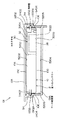
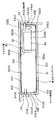
図12は第1のバッテリー2とバッテリー装着部150を示す斜視図、図13は第1のバッテリー2がバッテリー装着部150に装着された状態を示す説明図、図14(A)、(B)は第1のバッテリー2のコネクタ部30と撮像装置100の電子機器側コネクタ部50の説明図である。
図15は第2のバッテリー4がバッテリー装着部150に装着された状態を示す説明図、図16(A)、(B)は第2のバッテリー4のコネクタ部30と撮像装置100の電子機器側コネクタ部50の説明図である。
Next, the electronic apparatus of the present invention will be described.
In this embodiment, the electronic device is an imaging device such as a digital video camera.
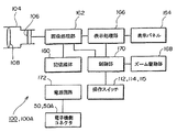
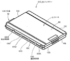
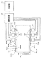
9 is a perspective view of the
12 is a perspective view showing the
FIG. 15 is an explanatory view showing a state in which the
図9に示すように、撮像装置100は、外装を構成する本体ケース102を有し、本体ケース102は、上下方向の高さと、高さよりも短い寸法の前後方向の長さと、長さよりも短い寸法の左右方向の幅とを有している。なお、本明細書において本体ケース102の左右は本体ケース102を前方(被写体側)から見た状態でいうものとする。
本体ケース102の上部には鏡筒104が組み込まれ、鏡筒104の後部に撮像素子106(図10)が組み込まれるとともに、鏡筒104には被写体像を撮像素子106に導く光学系108が組み込まれている。
光学系108は、ズームレンズやフォーカスレンズ、対物レンズなどを含んだ複数の光学部材で構成されている。
As illustrated in FIG. 9, the
A
The
本体ケース102は前方に臨む前壁102A、後方に臨む後壁102B、上方に臨む上壁102C、下方に臨む下壁102D、左側方に臨む左側壁102E、右側方に臨む右側壁102Fを有している。
本体ケース102の後壁102Bの上部には、撮影中の画像を視認するためのビューファインダー110が設けられている。
ビューファインダー110下方の後壁102B箇所には、動画撮影の開始/停止スイッチ112などが設けられている。
本体ケース102の上壁102C後部寄りには光学系108のズーム操作を行うためのズームスイッチ114などの撮影にまつわる操作スイッチを含む操作スイッチ115(図10)が配置されている。
本体ケース102の右壁には、静止画および動画などの画像や文字や記号などが表示される表示パネル164(図10)、画像情報および音声情報を記録する磁気テープカセットあるいは光ディスクあるいはメモリカードなどの記録媒体160(図10)が装脱される媒体収容部(不図示)が設けられている。
本体ケース102には、第1のバッテリー2を装脱可能に収容するバッテリー装着部150が設けられている。
The
On the upper part of the rear wall 102B of the
A moving image shooting start /
An operation switch 115 (FIG. 10) including operation switches related to photographing such as a
On the right wall of the
The
バッテリー装着部150は、バッテリー収容室151と、電子機器側コネクタ部50(図11)とを備えている。
バッテリー収容室151はその開口152から第1、第2のバッテリー2、4がその長さ方向(前後方向)に挿入され、開口152には開閉蓋154が揺動可能に設けられ、開口152を閉塞した状態で前方に臨む開閉蓋154部分によって前壁102Aが構成されている。
開閉蓋154は、開口152を閉塞した状態で不図示の係止手段により係止され閉塞状態を保持し、前記係止手段の係止を解除することで開口152を開放できるように構成されている。
図14、図16に示すように、電子機器側コネクタ部50は、第1、第2のバッテリー2、4が挿入される方向におけるバッテリー収容室151の奥部に配置され、第1、第2のバッテリー2、4のコネクタ部30に装着可能に設けられている。
バッテリー収容室151は、第1、第2のバッテリー2、4のケース10を収容するケース収容室151Aと、ケース収容室151Aの奥部に設けられ第1のバッテリー2のコネクタ部30を収容するコネクタ部収容室151Bを有し、コネクタ部収容室151Bに電子機器側コネクタ部50が設けられている。
図13、図15に示すように、ケース収容室151Aは、第1、第2のバッテリー2、4のケース10の上面10C、下面10D、左右の側面10Eに臨む上面5202、下面5204、左右の側面5206を有している。
The
The
The opening /
As shown in FIGS. 14 and 16, the electronic device-
The
As shown in FIGS. 13 and 15, the
図14、図16に示すように、コネクタ部収容室151Bは、ケース収容室151Aに接続され第1、第2のバッテリー2、4のコネクタ部30の前方を向いた前面3020に臨む奥面5208と、コネクタ部30の下方を向いた下面3022に臨む下面5210とを有している。
コネクタ部収容室151Bの下面5210は、ケース収容室151Aの下面5204よりもケース収容室151Aの上面5202寄りに変位した箇所に設けられている。
図12、図13、図15に示すように、ケース収容室151Aの左右の側面5206には、第1、第2のバッテリー2、4が挿入される方向に沿って延在し第1、第2のバッテリー2、4の左右の側面10Eの突出壁1002が係合可能な係合溝54が延在形成されている。
係合溝54は、側面5206の上下方向の中心部に対して上面5202または下面5204寄りの各側面5206箇所に設けられ、本実施例では、上面5202寄りの箇所に設けられている。
係合溝54は、互いに対向し上面5202又は下面5204に平行する2つの壁面5402、5404を有し、バッテリー収容室151の上下方向における電子機器側コネクタ部50の位置は、図13、図15に示すように、左右の係合溝54の2つの壁面5402、5404のうちの一方の壁面を基準として決定されており、本実施例では、下側に位置する壁面5404が、電子機器側コネクタ部50の厚さ方向における位置の基準となる面となっている。
ケース収容室151Aの係合溝54にバッテリーの突出壁1002が係合され、コネクタ部30が電子機器側コネクタ部50に接続されてケース10がケース収容室151Aに収容された状態で、ケース10の上面10Cと、上面10Cに対向するケース収容室151Aの上面5202(壁面)とが近接するように構成されている。本実施例では、ケース収容室151Aの上面5202は、撮像装置100の本体ケース102を構成する壁部103の内面(壁面)で構成されている。なお、ケース10がケース収容室151Aに収容された状態で、ケース10の上面10Cと、上面10Cに対向するケース収容室151Aの上面5202(壁面)とが近接するように構成すると、バッテリーがケース収容室151Aに収容された状態で、バッテリーのケース10を撮像装置100の本体ケース102を構成する壁部103の補強板として機能させることができ、撮像装置100の本体ケース102を薄肉化し、小型化を図る上で有利となる。
また、本実施例では、バッテリーの突出壁1002をケース収容室151Aの係合溝54に係合させつつバッテリーをバッテリー収容室151に挿入するようにし、コネクタ部収容室151Bの下面が、ケース収容室151Aの下面5204よりもケース収容室151Aの上面5202寄りに変位した箇所に設けられている。したがって、電子機器側コネクタ50の各接片61がコネクタ部収容室151Bの下面5210に支持されている部分をケース収容室151Aの下面5204よりも上方の箇所に位置させることができ、これにより、電子機器側コネクタ部50は、ケース収容室151Aの下面5204よりも下方に突出せず、したがって、ケース収容室151Aを、厚みの大きな第2のバッテリー4が収容できる大きさで形成すれば良く、バッテリー収容室151の上下方向の寸法を抑制する上で有利となる。
As shown in FIGS. 14 and 16, the connector
The
As shown in FIGS. 12, 13, and 15, the left and right side surfaces 5206 of the
The engaging
The
In a state where the protruding
Further, in this embodiment, the battery is inserted into the
図11、図14、図16に示すように、電子機器側コネクタ部50は、コネクタ部収容室151Bの奥面5208と下面5210に支持されケース収容室151Aの左右の側面5206を接続する方向に間隔をおいて並べられた複数の接片61を備え、複数の接片61は第1、第2のバッテリー2、4のコネクタ部30の複数の接片34に接触可能である。
As shown in FIGS. 11, 14, and 16, the electronic device-
図8に示すように、ばね60はバッテリー収容室151に設けられており、第1、第2のバッテリー2、4のコネクタ部30が電子機器側コネクタ部50に装着された状態でバッテリー2、4の部分に係止し、本実施例では、係止用凹部1004に係止し、電子機器側コネクタ部50方向に(前方に)第1、第2のバッテリー2、4を付勢するように構成されている。
具体的に説明すると、ばね60はばね鋼材などから細長い帯板状に形成され、その長手方向の両端に位置し係合溝54の壁面に取着される基部6006と、両側の基部6006を接続する弾性部6004と、弾性部6004の長さ方向のほぼ中心箇所にバッテリー側に向かって突出しバッテリー側に係止する係止部6002とを備える。
係止部6002は2つの傾斜部6002Aで構成され、電子機器側コネクタ部50寄りの傾斜部6002Aが、コネクタ部30寄りの係止用凹部1004の壁面に係止することで、第1、第2のバッテリー2、4を電子機器側コネクタ部50方向に(前方に)付勢するように構成されている。
本実施例では、係止部6002は、バッテリー収容室151の挿入方向に沿った長さの中心よりも奥部寄りの箇所で、ケース収容室151Aの左右の側面5206の係合溝54のうちの一方(右側)の係合溝54箇所のみに配設されている。
As shown in FIG. 8, the
More specifically, the
The locking
In the present embodiment, the locking
電子機器側コネクタ部50は、撮像装置100の電源回路172(図10)に接続されている。
図10に示すように、撮像装置100、100Aは、撮像素子106から出力された撮像信号に対して所定のデータ処理を行って画像データを生成し、この画像データを記憶媒体160に記録する画像処理部162と、前記画像データを表示パネル164に表示させる表示処理部166と、撮影光学系108の撮影倍率を変化させるズーム駆動部168と、各操作スイッチ112、114、115の操作に基づき、画像処理部162、表示処理部166、ズーム駆動部168などを制御する制御部170と、電子機器側コネクタ部50、50Aを介して第1のバッテリー2から供給された直流電源を画像処理部162、表示処理部166、ズーム駆動部168に供給する電源回路172などを備えている。
The electronic device
As illustrated in FIG. 10, the
次に作用効果について説明する。
第1のバッテリー2を撮像装置100に装着する際には、図9に示すように、開閉蓋154を開放し、第1のバッテリー2のケース10の上面10C、下面10D、左右の側面10Eのそれぞれを撮像装置100のケース収容室151Aの上面5202、下面5204、左右の側面5206のそれぞれに臨ませ、第1のバッテリー2の突出壁1002をバッテリー収容室151の係合溝54に挿入して押し込む。
これにより、図14(A)、(B)に示すように、コネクタ部30の接片34と電子機器側コネクタ部50の接片61とが接触して電子機器側コネクタ部50にコネクタ部30が装着され、コネクタ部30の前面3020がコネクタ部収容室151Bの奥面5208に近接され、コネクタ部30の下面3022がコネクタ部収容室151Bの下面5210に臨む。
この状態で、図13に示すように、第1のバッテリー2の上面10Cは、ケース収容室151Aの上面5202(壁面)と近接し、第1のバッテリー2の下面10Dは、ケース収容室151Aの下面5204との間に間隔をおいて位置する。
第1のバッテリー2がバッテリー収容室151に挿入される際、ばね60の係止凸部6002はいったん突出壁1002の縁部に当接して幅方向外方に弾性変形され突出壁1002の縁部上を摺動するが、やがて、コネクタ部30と電子機器側コネクタ部50とが装着されると、係止部6002が係止用凹部1004に係合する。このとき、ユーザーの手にはクリック感が伝わることになる。
この状態で、電子機器側コネクタ部50寄りの傾斜部6002Aが、コネクタ部30寄りの係止用凹部1004の壁面に係止し、弾性部6004の弾性力により第1のバッテリー2を電子機器側コネクタ部50方向に(前方に)付勢する。
次いで、開閉蓋154を閉塞する。
これにより、第1のバッテリー2からの直流電源が電源回路172を介して撮像装置100の各部に供給される。
第1のバッテリー2を取り外す際には、開閉蓋154を開放し、第1のバッテリー2の後部を把持してバッテリー収容室151から抜去する。
この際、ばね60の係止部6002は傾斜部6002Aを介して係止用凹部1004から外れ、突出壁1002の縁部に乗り上げた状態で突出壁1002の縁部を摺動し、突出壁1002の縁部から外れると元の状態に復帰する。
Next, the function and effect will be described.
When the
As a result, as shown in FIGS. 14A and 14B, the
In this state, as shown in FIG. 13, the
When the
In this state, the
Next, the opening /
As a result, the DC power from the
When removing the
At this time, the locking
次に、第2のバッテリー4を装着する場合について説明する。
第1のバッテリー2を装着する場合と同様に、開閉蓋154を開放し、第2のバッテリー4のケース10の上面10C、下面10D、左右の側面10Eのそれぞれを撮像装置100のケース収容室151Aの上面5202、下面5204、左右の側面5206のそれぞれに臨ませ、第2のバッテリー4の突出壁1002をバッテリー収容室151の係合溝54に挿入して押し込む。
これにより、図16(A)、(B)に示すように、コネクタ部30の接片34と電子機器側コネクタ部50の接片61とが接触して電子機器側コネクタ部50にコネクタ部30が装着され、コネクタ部30の前面3020がコネクタ部収容室151Bの奥面5208に近接され、コネクタ部30の下面3022がコネクタ部収容室151Bの下面5210に臨む。
この状態で、図15に示すように、第2のバッテリー4の上面10Cは、ケース収容室151Aの上面5202(壁面)と近接し、第2のバッテリー4の下面10Dは、ケース収容室151Aの下面5204と近接する。
第2のバッテリー4がバッテリー収容室151に挿入される際、第1のバッテリー2の場合と同様に、ばね60の係止凸部6002はいったん突出壁1002の縁部に当接して幅方向外方に弾性変形され突出壁1002の縁部上を摺動するが、やがて、コネクタ部30と電子機器側コネクタ部50とが装着されると、係止部6002が係止用凹部1004に係合する。このとき、ユーザーの手にはクリック感が伝わることになる。
この状態で、電子機器側コネクタ部50寄りの傾斜部6002Aが、コネクタ部30寄りの係止用凹部1004の壁面に係止し、弾性部6004の弾性力により第2のバッテリー4を電子機器側コネクタ部50方向に(前方に)付勢する。
次いで、開閉蓋154を閉塞する。
これにより、第2のバッテリー4からの直流電源が電源回路172を介して撮像装置100の各部に供給される。
第2のバッテリー4を取り外す際には、開閉蓋154を開放し、第2のバッテリー4の後部を把持してバッテリー収容室151から抜去する。
この際、ばね60の係止部6002は傾斜部6002Aを介して係止用凹部1004から外れ、突出壁1002の縁部に乗り上げた状態で突出壁1002の縁部を摺動し、突出壁1002の縁部から外れると元の状態に復帰する。
Next, a case where the
As in the case of mounting the
As a result, as shown in FIGS. 16A and 16B, the
In this state, as shown in FIG. 15, the
When the
In this state, the
Next, the opening /
As a result, DC power from the
When removing the
At this time, the locking
本実施例の撮像装置100によれば、バッテリーのコネクタ部30が電子機器側コネクタ部50に装着された状態でバッテリーの係止用凹部1004に係止し電子機器側コネクタ部50方向にバッテリーを付勢するばね60がバッテリー収容室151に設けられているので、バッテリー収容室151にバッテリーが収容された状態で開閉蓋154が開放されたとしても、バッテリーはばね60によってバッテリー収容室151に収容された状態が保持される。
したがって、仮に開閉蓋154が開放された状態で撮像装置100を傾けたり動かしたりしてもバッテリーの落下を防止できることは無論のこと、開閉蓋154が開放されてもバッテリーは安定した状態でバッテリー収容室151内に保持されているので、バッテリーの装脱操作を円滑かつ確実に行う上で有利となる。
また、ばね60によってバッテリーが電子機器側コネクタ部50方向に付勢されているので、バッテリーのコネクタ部30と電子機器側コネクタ部50との装着状態が安定して保持され、バッテリーのコネクタ部30から電子機器側コネクタ部50を介してなされる電源供給を安定して行う上で有利となる。
また、ばね60によってバッテリーが電子機器側コネクタ部50方向に付勢されているので、コネクタ部30と電子機器側コネクタ部50とが装着された状態でさらにコネクタ部30の接片34と電子機器側コネクタ部50の接片61とが互いに近接する方向に付勢されることになる。
したがって、コネクタ部30と電子機器側コネクタ部50とが単に装着されているだけの場合に比べて、接片同士の接触を良好に維持した状態で接片同士のオーバーラップ量を最小限度にでき、バッテリーの挿入方向におけるコネクタ部30および電子機器側コネクタ部50の寸法を削減する上で有利となり、ひいては撮像装置100の小型化を図る上で有利となる。
また、係止部6002を、バッテリー収容室151の挿入方向に沿った長さの中心よりも奥部寄りの箇所に設けたので、バッテリー収容室151に、例えば、バッテリーの前後方向の全ての部分を挿入せずにその一部のみを挿入するような場合でも、係止用凹部1004に係止部6002が係止でき、何ら設計変更を要せずに種々のバッテリーの装着状態に対応できて有利となる。
また、バッテリー収容室151にバッテリーの突出壁1002が係合される係合溝54が形成され、バッテリー収容室151においてバッテリーの厚さ方向における電子機器側コネクタ部50の位置は、係合溝54の2つの壁面5402、5404のうちの一方の壁面を基準として決定されている。
したがって、突出壁1002を基準としてコネクタ部30が設けられ厚さが異なる第1、第2のバッテリー2、4をその突出壁1002をバッテリー収容室151の係合溝54に係合させたときに、第1、第2のバッテリー2、4のコネクタ部30の位置が、電子機器側コネクタ部50の位置とそれぞれ合致するため、厚さが異なるこれら第1、第2のバッテリー2、4の双方をバッテリー収容室151に装着することができる。
According to the
Accordingly, it goes without saying that the battery can be prevented from falling even if the
In addition, since the battery is urged toward the electronic
Further, since the battery is urged toward the electronic device
Therefore, compared with the case where the
Further, since the locking
Further, an
Accordingly, when the first and
また、本実施例のバッテリーによれば、上述の撮像装置100に用いられることで、バッテリーのコネクタ部30と電子機器側コネクタ部50との装着状態が安定して保持され、バッテリーの撮像装置100への電源供給を安定して行う上で有利となる。
また、係止用凹部1004を介してバッテリーが電子機器側コネクタ部50方向に付勢されているので、コネクタ部30と電子機器側コネクタ部50とが単に装着されているだけの場合に比べて、接片同士の接触を良好に維持した状態で接片同士のオーバーラップ量を最小限度にでき、バッテリーの挿入方向におけるコネクタ部30および電子機器側コネクタ部50の寸法を削減する上で有利となり、ひいては撮像装置100の小型化を図る上で有利となる。
また、係止用凹部1004を、左右の側面10Eの前後方向の中心よりも前面10A寄りの箇所に設けたので、バッテリー収容室151に、例えば、バッテリーの前後方向の全ての部分を挿入せずにその一部のみを挿入するような場合でも、係止用凹部1004に係止部6002が係止でき、何ら設計変更を要せずに種々のバッテリーの装着状態に対応できて有利となる。
Further, according to the battery of the present embodiment, when used in the above-described
Further, since the battery is urged toward the electronic device
In addition, since the
次に実施例2について説明する。なお、以下の説明では実施例1と同様な箇所、部材に同一の符号を付して説明する。
図17は実施例2におけるバッテリーの斜視図、図18は実施例2のバッテリーおよび撮像装置の構成を示す説明図である。
Next, Example 2 will be described. In the following description, the same parts and members as those in the first embodiment are denoted by the same reference numerals.
FIG. 17 is a perspective view of the battery according to the second embodiment, and FIG. 18 is an explanatory diagram illustrating the configuration of the battery and the imaging device according to the second embodiment.
実施例2が実施例1と異なるのは、バッテリーのケース10に係止用凹部1004に加えて複数の識別用凹部1010が設けられ、また、撮像装置100のバッテリー装着部150のケース収容室151Aに識別用凹部1010を検出する複数のセンサ62が設けられている点であり、その他の構成は実施例1と同様である。なお、以下では説明の便宜上、第1、第2のバッテリー2、4を総称してバッテリー6という。
The second embodiment differs from the first embodiment in that the
図17、図18に示すように、バッテリー6のケース10の左右の側面10Eにはバッテリー6の特性を識別するための識別用凹部1010が前後方向に間隔をおいて複数設けられている。
ここで、バッテリー6の特性とは、例えば、バッテリー6の容量、充電電流の値、急速充電が可能か否かを示す情報などである。
本実施例では、ケース10の左右の側面10Eに、実施例1と同様に、厚さ方向におけるコネクタ部30の位置の基準となる突出壁1002が設けられており、識別用凹部1010は突出壁1002の長さ方向(前後方向)に間隔をおいた複数箇所を切り欠くことで設けられている。
各識別用凹部1010は、バッテリー6の特性に対応してその数、あるいは、ケース10の長さ方向における位置が定められて形成されている。
As shown in FIGS. 17 and 18, the left and right side surfaces 10 </ b> E of the
Here, the characteristics of the battery 6 include, for example, the capacity of the battery 6, the value of the charging current, information indicating whether or not rapid charging is possible, and the like.
In the present embodiment, the left and right side surfaces 10E of the
The number of the concave portions for
撮像装置100のバッテリー収容室151には、バッテリー6のコネクタ部30が電子機器側コネクタ部50に装着された状態で各識別用凹部1010の有無を検出する複数のセンサ62(バッテリー6の部分を検出するセンサ)が設けられ、撮像装置100には、複数のセンサ62の検出信号に基づいてバッテリー収容室151に収容されたバッテリー6の特性を識別しその識別結果を制御部170に供給する識別回路64(特許請求の範囲の識別手段に相当)が設けられている。
本実施例では、バッテリー収容室151に、実施例1と同様に、突出壁1002が係合される係合溝54が挿入方向に沿って延在形成され、係合溝54には実施例1と同様に係止用凹部1004に係合するばね60が配設され、また、係合溝54には、前記センサ62として、コネクタ部30が電子機器側コネクタ部50に装着された状態で識別用凹部1010に没入することで前記検出信号を出力するマイクロスイッチが配設されている。
実施例2では、撮像装置100の左右の係合溝54にそれぞれ3つのセンサ64を配置し、合計6つのセンサ64を設けたので、これら6つのセンサ64からの検出信号の組み合わせによって64通りの情報を識別できることになるが、センサ64の数や識別用凹部1010の数は、5つ以下であってもよく、あるいは、7つ以上であってもよく、任意に設定できることは無論である。
In the
In the present embodiment, as in the first embodiment, the
In the second embodiment, three
実施例2によれば、バッテリー6がバッテリー収容室151に収容されると、各センサ62によって識別用凹部1010の有無が検出され、それら検出信号に基づいて識別回路64がバッテリー6の特性を識別する。
したがって、実施例2によれば、実施例1の効果に加え、撮像装置100の制御部170はその識別結果に基づいてバッテリー6の特性に対応した様々な制御を行うことができる。
例えば、装着されたバッテリー6の容量の識別結果に基づいて、その容量が撮像装置100に用いるには不足していると判断した場合には、バッテリー6からの電源供給を禁止することで、撮像装置100が電源不足ですぐにバッテリー切れになるといった不具合の発生を回避できる。
また、バッテリー6が装着される電子機器がバッテリー6を充電する充電装置である場合には、実施例2と同様のセンサ1010と識別回路64を設けることにより、識別回路64によって識別された適切な充電電流の値、急速充電が可能か否かを示す情報に基づいてバッテリー6への充電電流や充電時間を適切に制御することができる。
According to the second embodiment, when the battery 6 is accommodated in the
Therefore, according to the second embodiment, in addition to the effects of the first embodiment, the
For example, when it is determined that the capacity is insufficient for use in the
Further, when the electronic device to which the battery 6 is attached is a charging device that charges the battery 6, by providing the
なお、実施例2では、識別用凹部1010によって識別するバッテリー6の特性として、バッテリー6の容量を示す情報、適切な充電電流の値、急速充電が可能か否かを示す情報を例示したが、識別用凹部1010によって識別する特性として、その他従来公知の様々な特性を用いることが可能であり、それら特性に基づいてどのような制御動作を行うかは任意である。
また、実施例1、2では、電子機器が撮像装置であった場合について説明したが、電子機器は撮像装置に限定されるものではなく、例えば、照明装置、オーディオ装置、通信装置、あるいは、バッテリー充電装置などバッテリーが装着されるものであれば適用可能であることはもちろんである。
In the second embodiment, as the characteristics of the battery 6 to be identified by the
In the first and second embodiments, the case where the electronic device is an imaging device has been described. However, the electronic device is not limited to the imaging device. For example, the lighting device, the audio device, the communication device, or the battery Of course, the present invention can be applied to any device that is equipped with a battery such as a charging device.
2……第1のバッテリー、4……第2のバッテリー、6……バッテリー、10……ケース、10A……前面、10B……後面、10C……上面、10D……下面、10E……側面、1004……係止用凹部、30……コネクタ部、50……電子機器側コネクタ部、60……ばね、100……撮像装置、150……バッテリー装着部、151……バッテリー収容室。
2 ... 1st battery, 4 ... 2nd battery, 6 ... Battery, 10 ... Case, 10A ... Front, 10B ... Rear, 10C ... Top, 10D ... Bottom, 10E ... Side , 1004... Recessed portion for locking, 30... Connector portion, 50 .. electronic device side connector portion, 60... Spring, 100.
Claims (10)
前記バッテリー装着部は、前記バッテリーが挿入されるバッテリー収容室と、前記挿入方向における前記バッテリー収容室の奥部に設けられ前記バッテリーの前記前面に設けられたコネクタ部が装着される電子機器側コネクタ部とを備え、
前記バッテリー収容室には、前記バッテリーの前記2つの側面から前記幅方向外方に突出する突出壁が係合される係合溝が前記挿入方向に沿って延在形成されており、
前記係合溝の壁面には、前記バッテリーの前記突出壁に設けた係止用凹部に係止する係止部を有するばねが設けられており、
前記ばねは、前記係止部が前記係止用凹部に係止することで、前記バッテリーを前記電子機器側コネクタ部方向に付勢する
ことを特徴とする電子機器。 An electronic device provided with a battery mounting portion for mounting a front surface, a rear surface facing the front surface, and a battery having two side surfaces connected to the front surface and the rear surface and positioned at both ends in the width direction of the case. There,
The battery mounting portion includes a battery housing chamber into which the battery is inserted, and an electronic device side connector to which a connector portion provided in the back of the battery housing chamber in the insertion direction is mounted. With
In the battery housing chamber, an engagement groove is formed extending along the insertion direction to be engaged with a protruding wall protruding outward in the width direction from the two side surfaces of the battery.
The wall surface of the engagement groove is provided with a spring having a locking portion that is locked to a locking recess provided on the protruding wall of the battery,
The electronic device is characterized in that the spring urges the battery in the direction of the electronic device side connector portion when the locking portion is locked in the locking recess .
ことを特徴とする請求項3に記載の電子機器。 The electronic device according to claim 3, wherein the sensor is disposed in the engagement groove .
前記ケースの内部に収容された電池セルと、
前記ケースの前面に設けられたコネクタ部とを備え、
前記ケースの2つの側面には、前記幅方向外方に突出しつつ前記前後方向に延在する突出壁が設けられており、
前記突出壁には、電子機器のバッテリー収容室における前記突出壁と係合する係合溝の壁面に設けられたばねの係止部と係止する係止用凹部が形成されており、
前記係止用凹部と前記ばねの係止部と係止することで、前記ケースが前記電子機器の電子機器側コネクタ部方向に付勢される
ことを特徴とするバッテリー。 And upper and lower surfaces positioned at both ends in the thickness direction, located in the width direction of the ends of dimension greater than the thickness, and the two side surfaces facing each other, located in the longitudinal direction of the ends of larger size than the width A flat rectangular plate-like case having a front surface and a rear surface facing each other ;
Battery cells housed inside the case;
A connector portion provided on the front surface of the case;
Projecting walls extending in the front-rear direction while projecting outward in the width direction are provided on two side surfaces of the case ,
The protruding wall is formed with a locking recess for locking with a locking portion of a spring provided on a wall surface of an engaging groove that engages with the protruding wall in the battery housing chamber of the electronic device.
The battery is characterized in that the case is urged toward the electronic device side connector portion of the electronic device by being engaged with the engaging concave portion and the engaging portion of the spring .
ことを特徴とする請求項6〜8のいずれかに記載のバッテリー。The battery according to claim 6, wherein the battery is a battery.
ことを特徴とする請求項6〜9のいずれかに記載のバッテリー。The battery according to any one of claims 6 to 9.
Priority Applications (10)
| Application Number | Priority Date | Filing Date | Title |
|---|---|---|---|
| JP2004365645A JP4635597B2 (en) | 2004-12-17 | 2004-12-17 | Electronics and batteries |
| TW094137654A TWI313079B (en) | 2004-11-05 | 2005-10-27 | Battery and electronic apparatus |
| US11/262,795 US7700224B2 (en) | 2004-12-17 | 2005-11-01 | Electronic apparatus with secure battery inserting and removing operation |
| AU2005301561A AU2005301561B2 (en) | 2004-11-05 | 2005-11-04 | Battery and electronic apparatus |
| US11/718,652 US8409748B2 (en) | 2004-11-05 | 2005-11-04 | Battery and electronic apparatus |
| EP05803414A EP1825538A1 (en) | 2004-11-05 | 2005-11-04 | Battery and electronic apparatus |
| MX2007004014A MX2007004014A (en) | 2004-11-05 | 2005-11-04 | Battery and electronic apparatus. |
| PCT/JP2005/020684 WO2006049332A1 (en) | 2004-11-05 | 2005-11-04 | Battery and electronic apparatus |
| KR1020077010271A KR20070072569A (en) | 2004-11-05 | 2005-11-04 | Battery and electronic apparatus |
| HK07111583.3A HK1106331A1 (en) | 2004-11-05 | 2007-10-26 | Battery and electronic apparatus |
Applications Claiming Priority (1)
| Application Number | Priority Date | Filing Date | Title |
|---|---|---|---|
| JP2004365645A JP4635597B2 (en) | 2004-12-17 | 2004-12-17 | Electronics and batteries |
Publications (2)
| Publication Number | Publication Date |
|---|---|
| JP2006172969A JP2006172969A (en) | 2006-06-29 |
| JP4635597B2 true JP4635597B2 (en) | 2011-02-23 |
Family
ID=36596281
Family Applications (1)
| Application Number | Title | Priority Date | Filing Date |
|---|---|---|---|
| JP2004365645A Expired - Fee Related JP4635597B2 (en) | 2004-11-05 | 2004-12-17 | Electronics and batteries |
Country Status (2)
| Country | Link |
|---|---|
| US (1) | US7700224B2 (en) |
| JP (1) | JP4635597B2 (en) |
Families Citing this family (9)
| Publication number | Priority date | Publication date | Assignee | Title |
|---|---|---|---|---|
| JP2006302693A (en) * | 2005-04-21 | 2006-11-02 | Sony Corp | Battery |
| US8902568B2 (en) * | 2006-09-27 | 2014-12-02 | Covidien Lp | Power supply interface system for a breathing assistance system |
| CN101728499B (en) * | 2008-10-31 | 2012-12-19 | 深圳富泰宏精密工业有限公司 | Battery cover structure |
| CN101740731B (en) * | 2008-11-12 | 2013-03-13 | 深圳富泰宏精密工业有限公司 | Battery cover structure |
| DE102013201729A1 (en) * | 2013-02-04 | 2014-08-07 | Robert Bosch Gmbh | Battery cell with positioning projection, module housing with positioning receiver, battery module with battery cell and module housing as well as battery with battery module and motor vehicle with battery |
| KR102028172B1 (en) * | 2013-06-25 | 2019-10-02 | 삼성에스디아이 주식회사 | Battery pack |
| JP5892630B1 (en) * | 2014-11-14 | 2016-03-23 | Necプラットフォームズ株式会社 | Battery pack housing structure and electronic device |
| US20160156003A1 (en) * | 2014-12-02 | 2016-06-02 | Ojmar, S.A. | Portable battery device |
| JP2020003613A (en) * | 2018-06-27 | 2020-01-09 | キヤノン株式会社 | Electronic apparatus |
Citations (2)
| Publication number | Priority date | Publication date | Assignee | Title |
|---|---|---|---|---|
| JP2003045386A (en) * | 2001-08-01 | 2003-02-14 | Sony Corp | Battery pack and assembling method of the same |
| JP2004120140A (en) * | 2002-09-25 | 2004-04-15 | Sanyo Electric Co Ltd | Mobile phone provided with battery pack |
Family Cites Families (4)
| Publication number | Priority date | Publication date | Assignee | Title |
|---|---|---|---|---|
| US6445948B1 (en) * | 1998-04-03 | 2002-09-03 | Medtronic, Inc. | Implantable medical device having a substantially flat battery |
| US6421233B1 (en) * | 2000-06-12 | 2002-07-16 | High Tech Computer Corporation | Pocket personal computer with improved battery compartment enclosing structure |
| TWI228961B (en) * | 2002-10-21 | 2005-03-01 | Benq Corp | Portable apparatus with inward-pushing triggered mechanism for ejecting add-on device |
| JP4622502B2 (en) * | 2004-12-20 | 2011-02-02 | ソニー株式会社 | battery |
-
2004
- 2004-12-17 JP JP2004365645A patent/JP4635597B2/en not_active Expired - Fee Related
-
2005
- 2005-11-01 US US11/262,795 patent/US7700224B2/en not_active Expired - Fee Related
Patent Citations (2)
| Publication number | Priority date | Publication date | Assignee | Title |
|---|---|---|---|---|
| JP2003045386A (en) * | 2001-08-01 | 2003-02-14 | Sony Corp | Battery pack and assembling method of the same |
| JP2004120140A (en) * | 2002-09-25 | 2004-04-15 | Sanyo Electric Co Ltd | Mobile phone provided with battery pack |
Also Published As
| Publication number | Publication date |
|---|---|
| US7700224B2 (en) | 2010-04-20 |
| US20060134513A1 (en) | 2006-06-22 |
| JP2006172969A (en) | 2006-06-29 |
Similar Documents
| Publication | Publication Date | Title |
|---|---|---|
| JP4232851B2 (en) | Battery device | |
| US10326116B2 (en) | Battery device, electronic apparatus, and battery system | |
| JP4123516B2 (en) | Battery device | |
| US7648795B2 (en) | Electronic apparatus | |
| US7700224B2 (en) | Electronic apparatus with secure battery inserting and removing operation | |
| JP2008153241A (en) | Battery device | |
| US20080050648A1 (en) | Battery device, electronic apparatus, and battery system | |
| JP6107846B2 (en) | Battery system | |
| US8409748B2 (en) | Battery and electronic apparatus | |
| US7493635B2 (en) | Recording medium drive device, electronic equipment having the recording medium drive device, and recording medium cartridge | |
| JP4999269B2 (en) | Batteries and electronics | |
| JP6249032B2 (en) | battery | |
| JP4779353B2 (en) | Batteries and electronics | |
| US11196121B2 (en) | Battery device, electronic apparatus, and battery system | |
| KR20060110773A (en) | Battery | |
| JP2006165983A (en) | Electronic apparatus |
Legal Events
| Date | Code | Title | Description |
|---|---|---|---|
| A977 | Report on retrieval |
Free format text: JAPANESE INTERMEDIATE CODE: A971007 Effective date: 20090806 |
|
| RD02 | Notification of acceptance of power of attorney |
Free format text: JAPANESE INTERMEDIATE CODE: A7422 Effective date: 20090817 |
|
| A131 | Notification of reasons for refusal |
Free format text: JAPANESE INTERMEDIATE CODE: A131 Effective date: 20091013 |
|
| RD04 | Notification of resignation of power of attorney |
Free format text: JAPANESE INTERMEDIATE CODE: A7424 Effective date: 20091013 |
|
| A521 | Request for written amendment filed |
Free format text: JAPANESE INTERMEDIATE CODE: A523 Effective date: 20091207 |
|
| TRDD | Decision of grant or rejection written | ||
| A01 | Written decision to grant a patent or to grant a registration (utility model) |
Free format text: JAPANESE INTERMEDIATE CODE: A01 Effective date: 20101026 |
|
| A01 | Written decision to grant a patent or to grant a registration (utility model) |
Free format text: JAPANESE INTERMEDIATE CODE: A01 |
|
| A61 | First payment of annual fees (during grant procedure) |
Free format text: JAPANESE INTERMEDIATE CODE: A61 Effective date: 20101108 |
|
| FPAY | Renewal fee payment (event date is renewal date of database) |
Free format text: PAYMENT UNTIL: 20131203 Year of fee payment: 3 |
|
| FPAY | Renewal fee payment (event date is renewal date of database) |
Free format text: PAYMENT UNTIL: 20131203 Year of fee payment: 3 |
|
| R250 | Receipt of annual fees |
Free format text: JAPANESE INTERMEDIATE CODE: R250 |
|
| R250 | Receipt of annual fees |
Free format text: JAPANESE INTERMEDIATE CODE: R250 |
|
| LAPS | Cancellation because of no payment of annual fees |