JP2010035092A - Video signal processing method, and video image signal processor - Google Patents
Video signal processing method, and video image signal processor Download PDFInfo
- Publication number
- JP2010035092A JP2010035092A JP2008197440A JP2008197440A JP2010035092A JP 2010035092 A JP2010035092 A JP 2010035092A JP 2008197440 A JP2008197440 A JP 2008197440A JP 2008197440 A JP2008197440 A JP 2008197440A JP 2010035092 A JP2010035092 A JP 2010035092A
- Authority
- JP
- Japan
- Prior art keywords
- video
- osd
- frame rate
- video signal
- signal
- Prior art date
- Legal status (The legal status is an assumption and is not a legal conclusion. Google has not performed a legal analysis and makes no representation as to the accuracy of the status listed.)
- Granted
Links
Images


Abstract
Description
本発明は、複数の映像を合成する映像信号処理方法及び映像信号処理装置に関する。 The present invention relates to a video signal processing method and a video signal processing apparatus that synthesize a plurality of videos.
現行のテレビジョン放送では、通常60Hz(実際には59.94Hz)のフィールド周波数で映像が送信されている。このテレビジョン放送で、映画やフィルム撮影されたソースなど24Hzで作製されている映像ソースを送信する場合、2−3プルダウンと言われる方法が用いられている。これは、放送の5フィールドに映像ソースの2コマを割り当てる処理である。例えばソース映像の奇数コマを2フィールドに割り当て、偶数コマを3フィールドに割り当てることで、24Hzの映像を60Hzの放送信号に変換することができる。 In current television broadcasting, video is normally transmitted at a field frequency of 60 Hz (actually 59.94 Hz). In this television broadcasting, when transmitting a video source produced at 24 Hz, such as a movie or film source, a method called 2-3 pull-down is used. This is a process of assigning two frames of the video source to the five broadcast fields. For example, by assigning odd frames of the source video to 2 fields and assigning even frames to 3 fields, it is possible to convert a 24 Hz video into a 60 Hz broadcast signal.
近年、液晶の動画表示特性の改善などのため、フレームレート変換を行い120Hzで動作するテレビジョン受像機が増えている。特開2001−346131号公報(特許文献1)には、このようなテレビジョン受像機で映画などの2−3プルダウンされた放送信号を表示する場合のフレームレート変換方法が記載されている。これは、入力された放送信号が2−3プルダウンされたものであることを検出すると、元の24Hzの映像ソースの各コマを5回連続して表示するフレームレート変換方法である。 In recent years, television receivers that perform frame rate conversion and operate at 120 Hz are increasing in order to improve the moving image display characteristics of liquid crystal. Japanese Patent Application Laid-Open No. 2001-346131 (Patent Document 1) describes a frame rate conversion method in the case where a 2-3 pull-down broadcast signal such as a movie is displayed on such a television receiver. This is a frame rate conversion method in which each frame of the original 24 Hz video source is continuously displayed five times when it is detected that the input broadcast signal has been pulled down 2-3.
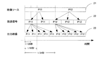
図10は24Hzの映像ソースを2−3プルダウンし、その放送信号を表示するまでの従来例の動作を示した図である。図10においては横方向が時間の流れを示し、P11、P12が各コマの映像を示している。映像ソース21は24Hzの映像信号、放送信号22は60Hzの映像信号、出力映像23は120Hzの映像信号である。映像ソース21から放送信号22を生成する場合には2−3プルダウンが行われる。すなわち、映像ソース21の各コマP11、P12が、放送信号22では2コマのP11、3コマのP12のように、各フィールドに割り当てられる。続いて、受像機が2−3プルダウンされた放送信号22を検出すると、各コマP11、P12を抜き出して、それぞれ出力映像23の5フレームずつに割り当てる。このようにすることで、120Hzで映像信号を表示する場合であっても、P11、P12を元の映像ソース22と同じ時間間隔で表示することができる。
FIG. 10 is a diagram showing the operation of the conventional example until a 24 Hz video source is pulled down 2-3 and the broadcast signal is displayed. In FIG. 10, the horizontal direction indicates the flow of time, and P11 and P12 indicate the video of each frame. The
このようなテレビジョン受像機で60HzのOSD(on−screen display)映像を入力映像に合成する場合の構成例を図11に示す。OSD映像とは、入力映像にスーパーインポーズして表示する映像のことであり、アイコンや写真などのグラフィックスや文字などで構成されている。 FIG. 11 shows a configuration example in the case of synthesizing a 60 Hz OSD (on-screen display) image with an input image with such a television receiver. The OSD video is a video that is displayed superimposed on the input video, and is composed of graphics such as icons and photos, characters, and the like.
図11において、2−3プルダウン検出部24は入力映像が2−3プルダウンにより変換された映像であるかを検出して変換情報として出力する。OSD生成部25は入力映像にスーパーインポーズするOSD映像を生成する。映像合成部26は入力映像とOSD映像を合成して出力する。フレームレート変換部27は2−3プルダウン検出部24の変換情報を元に合成映像のフレームレートを120Hzに変換して出力する。
In FIG. 11, a 2-3 pull-
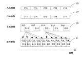
このような構成における動作の例を図12に示す。図12において、入力映像28は2−3プルダウンされた60Hzの映像、OSD映像29は入力映像28に合成する60Hzの映像である。また、合成映像30は入力映像28とOSD映像29を合成した映像、出力映像31は合成映像30をフレームレート変換して120Hzに変換した映像である。P13、P14は入力映像28の各コマであり、同じ符号のコマは同じソースから2−
3プルダウンされている。D13、D14、D15、D16、D17はOSD映像29の各コマを示している。
An example of the operation in such a configuration is shown in FIG. In FIG. 12, an
3 is pulled down.
入力映像28は2−3プルダウンによりP13が2コマ、P14が3コマで入力されている。この入力映像にOSD映像29を合成すると合成映像30のようになり、1コマ目はP13とD13の合成映像、2コマ目はP13とD14の合成映像、3コマ目はP14とD15の合成映像が得られる。この合成映像を上述した方法で120Hzに変換すると出力映像31のようになり、D14、D16、D17のOSD映像が欠落してしまう。また、OSD映像が時間方向において不均等に表示されるため違和感のある映像となってしまう。
The
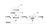
このような問題を解決する技術として、特開2004−120757号公報(特許文献2)が開示されている。図13は特許文献2の構成例を示す図である。図13において、OSD生成部32はOSDの映像を出力する。映像合成部33は制御信号の情報を元に入力映像とOSD生成部32から出力されたOSD映像を合成し、映像処理部34は制御信号の情報を元に合成映像に処理を加えて出力する。
As a technique for solving such a problem, Japanese Patent Application Laid-Open No. 2004-120757 (Patent Document 2) is disclosed. FIG. 13 is a diagram illustrating a configuration example of
特許文献2では、合成されたOSD映像部分と、入力映像部分でそれぞれ異なるフレームレート変換方法をスイッチング選択により切り換えて処理する。例えば、OSD映像部分では全てのフレームを使用して映像を出力するようにすることで、OSD映像部分の映像の欠落や不均等な映像再生を防ぐことができる。
上述した従来の技術では、合成映像に対して、各部分ごとにフレームレート変換方法を切り換える。しかし、この方法によって透過性のあるOSD映像を合成した場合、OSD映像と、OSD映像に重ならない部分にある入力映像の境界部分で、フレームレート変換方法の違いによる違和感が発生してしまう。 In the conventional technique described above, the frame rate conversion method is switched for each portion of the synthesized video. However, when a transparent OSD image is synthesized by this method, a sense of incongruity due to a difference in the frame rate conversion method occurs at the boundary portion between the OSD image and the input image that does not overlap the OSD image.
また、上述した従来の技術では、合成するOSD映像の位置情報やそのフレームレート変換方法を指定し、フレームレート変換方法を切り換える処理が必要となる。そのため、システムの負荷増大や肥大化が課題であった。 Further, in the conventional technique described above, it is necessary to specify the position information of the OSD video to be synthesized and the frame rate conversion method thereof, and to switch the frame rate conversion method. Therefore, increasing the load on the system and increasing the size of the system have been problems.
本発明は上記実情に鑑みてなされたものであって、簡単な構成でOSD映像の欠落や不均等を解消し、かつOSD映像の合成部分とそれ以外の部分の映像の違和感を抑えることができる映像信号処理方法及び装置を提供することを目的とする。 The present invention has been made in view of the above circumstances, and it is possible to eliminate omission and non-uniformity of OSD video with a simple configuration, and to suppress a sense of incongruity between the synthesized portion of the OSD video and the other video. An object is to provide a video signal processing method and apparatus.
上記目的を達成するために本発明の第一の発明は以下の構成を採用する。すなわち、
第一のフレームレートを持つ第一の映像信号を受信するステップと、
第一のフレームレートを持つ第二の映像信号を生成する生成ステップと、
前記第一の映像信号および第二の映像信号から第一のフレームレートを持つ合成信号を作成する合成ステップと、
前記合成信号を第三のフレームレートに変換する変換ステップとを有し、
前記第一の映像信号に、第二のフレームレートから第一のフレームレートに変換する前処理が施されていた場合、前記生成ステップは、前記第二の映像信号の元信号を第二のフレームレートで生成するステップと、前記元信号を第一のフレームレートに変換することにより前記第二の映像信号を生成するステップを含む
ことを特徴とする映像信号処理方法である。
In order to achieve the above object, the first aspect of the present invention employs the following configuration. That is,
Receiving a first video signal having a first frame rate;
Generating a second video signal having a first frame rate;
Creating a composite signal having a first frame rate from the first video signal and the second video signal;
Converting the combined signal to a third frame rate,
When the preprocessing for converting the second frame rate to the first frame rate has been performed on the first video signal, the generating step converts the original signal of the second video signal to the second frame. A video signal processing method comprising: generating at a rate; and generating the second video signal by converting the original signal to a first frame rate.
また、本発明の第二の発明は以下の構成を採用する。すなわち、
第一のフレームレートを持つ第一の映像信号を受信する受信部と、
第一のフレームレートを持つ第二の映像信号を生成する生成部と、
前記第一の映像信号および第二の映像信号から第一のフレームレートを持つ合成信号を作成する合成部と、
前記合成信号を第三のフレームレートに変換する変換部とを備え、
前記第一の映像信号に、第二のフレームレートから第一のフレームレートに変換する前処理が施されていた場合、前記生成部は前記第二の映像信号の元信号を第二のフレームレートで生成し、前記元信号を第一のフレームレートに変換することにより前記第二の映像信号を生成する
ことを特徴とする映像信号処理装置である。
The second aspect of the present invention employs the following configuration. That is,
A receiver for receiving a first video signal having a first frame rate;
A generator for generating a second video signal having a first frame rate;
A synthesis unit for creating a synthesized signal having a first frame rate from the first video signal and the second video signal;
A conversion unit that converts the combined signal into a third frame rate;
When the preprocessing for converting the second video rate to the first frame rate is performed on the first video signal, the generation unit converts the original signal of the second video signal to the second frame rate. And generating the second video signal by converting the original signal into a first frame rate.
本発明によれば、OSD映像信号の欠落がなく、時間的に均等にフレームレート変換されるようにOSD映像信号を生成して入力映像と合成することにより、簡単な構成でOSD映像の欠落を解消できる。また、OSD映像の合成部分とそれ以外の部分の映像の違和感を抑えることができる。 According to the present invention, an OSD video signal is generated and synthesized with an input video so that the OSD video signal is not lost and the frame rate conversion is performed evenly in time. Can be resolved. In addition, it is possible to suppress a sense of discomfort between the synthesized part of the OSD video and the video of the other part.
以下、本発明の実施の形態について、図面を用いて詳細に説明する。 Hereinafter, embodiments of the present invention will be described in detail with reference to the drawings.
(実施例1)
実施例1は本発明の映像信号処理方法の例であり、その構成を図6のブロック図を用いて説明する。本実施例の装置は、受信部61で放送信号である60Hzのインターレース映像信号(60i)を受信し、IP変換部62で60Hzのプログレッシブ映像信号(60p)に変換している。図6において、この60pの映像信号を入力映像として扱う。
Example 1
The first embodiment is an example of the video signal processing method of the present invention, and its configuration will be described with reference to the block diagram of FIG. In the apparatus according to the present embodiment, the receiving
2−3プルダウン検出部11は入力映像(60p)が2−3プルダウンにより24Hzから変換された映像であるかを検出して変換情報として出力する。OSD生成部12は入力映像に合成するOSD映像(60p)を生成する。映像合成部13は入力映像とOSD映像を合成して合成映像を出力する。フレームレート変換部14は2−3プルダウン検出部11の変換情報を元に合成映像のフレームレートを120Hz(120p)に変換して出力する。
The 2-3 pull-down detection unit 11 detects whether the input video (60p) is a video converted from 24 Hz by 2-3 pull-down, and outputs it as conversion information. The
なお、上述した入力映像は本発明における第一の映像信号に、OSD映像は第二の映像信号に、合成映像は合成信号に、それぞれ該当する。また、本発明における第一のフレームレートは本実施例では60Hzであり、第二のフレームレートは24Hzであり、第三のフレームレートは120Hzである。 The input video described above corresponds to the first video signal in the present invention, the OSD video corresponds to the second video signal, and the composite video corresponds to the composite signal. In the present embodiment, the first frame rate in the present invention is 60 Hz, the second frame rate is 24 Hz, and the third frame rate is 120 Hz.
続いて、実施例1で行う処理の流れを図1〜図3のフローチャートを用いて説明する。 Subsequently, the flow of processing performed in the first embodiment will be described with reference to the flowcharts of FIGS.
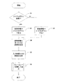
図1において、動作が開始されると、2−3プルダウン検出部11は入力映像が2−3プルダウンされた映像であるかを判定する(ステップS1)。 In FIG. 1, when the operation is started, the 2-3 pull-down detection unit 11 determines whether the input video is a video pulled down 2-3 (step S1).
2−3プルダウンされた映像であった場合には、24Hzに対応したフレームレート変換処理を行うため、2−3プルダウン検出部11は入力映像が2−3プルダウンされた映像であるという情報を変換情報として出力する(ステップS2)。2−3プルダウンされた映像でなかった場合、2−3プルダウン検出部11は入力映像が2−3プルダウンされ
た映像ではないという情報を変換情報として出力する(ステップS3)。
If the video is 2-3 pulled down, the 2-3 pulldown detection unit 11 converts the information that the input video is 2-3 pulled down in order to perform frame rate conversion processing corresponding to 24 Hz. It outputs as information (step S2). If the video is not 2-3 pulled down, the 2-3 pull down detection unit 11 outputs information that the input video is not a video pulled down 2-3 as conversion information (step S3).
そして、OSD生成部12はステップS2またはステップS3で出力された変換情報に従ったOSD映像を生成して出力する(ステップS4)。
Then, the
生成されたOSD映像は映像合成部13によって入力映像と合成して出力され(ステップS5)、フレームレート変換部14ではステップS2またはステップS3で出力された変換情報に応じたフレームレート変換を行い、映像を出力する(ステップS6)。
The generated OSD video is synthesized with the input video by the
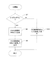
図2は変換情報に従ったOSD映像の生成(ステップS4)の動作を説明するフローチャートである。図2において、映像信号の入力が開始されると、2−3プルダウン検出部11は、変換情報の内容を確認し、入力映像が2−3プルダウンであるかを判定する(ステップS7)。 FIG. 2 is a flowchart for explaining the operation of generating the OSD video (step S4) according to the conversion information. In FIG. 2, when the input of the video signal is started, the 2-3 pull-down detection unit 11 confirms the content of the conversion information and determines whether the input video is 2-3 pull-down (step S7).
入力映像が2−3プルダウンであった場合、OSD生成部12は24Hzで再生されたときに動きの違和感が無いように24HzのタイミングでOSDの映像を作成(OSD元映像)する(ステップS8)。さらに前記OSD元映像を放送と同様のタイミングで映像が表示されるように60HzのOSD映像に変換して出力する(ステップS9)。なお、2−3プルダウンが本発明における前処理に当たり、OSD元映像が本発明における元信号に当たる。
When the input video is 2-3 pull-down, the
一方、入力映像が2−3プルダウンでなかった場合、OSD生成部12は、直接に、60HzのタイミングでOSDの映像を生成して出力する(ステップS10)。
On the other hand, when the input video is not 2-3 pulldown, the
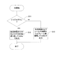
図3はフレームレート変換(ステップS6)の動作を説明するフローチャートである。図3において、動作が開始されると、フレームレート変換部14は変換情報が2−3プルダウンであるかを判定する(ステップS11)。
FIG. 3 is a flowchart for explaining the operation of frame rate conversion (step S6). In FIG. 3, when the operation is started, the frame
入力映像が2−3プルダウンであった場合、フレームレート変換部14は、まず合成映像の1コマ目を1/120秒の映像として5回繰り返して出力する。次に合成映像の3コマ目を1/120秒の映像として5回繰り返して出力する(ステップS12)。この方法によれば、同じ1/120秒の1コマを5回繰り返すことで1コマの映像を1/24秒間表示することになる。これにより、映像の欠落や動きの違和感なく元の24Hzの映像を再生することができる。
When the input video is 2-3 pull-down, the frame
入力映像が2−3プルダウンでなかった場合、フレームレート変換部14は、合成映像からフレーム内補間またはフレーム間補間により、60Hzの映像を変換して120Hzの映像を作成し、出力する(ステップS13)。
If the input video is not 2-3 pulldown, the frame
図4は入力映像が2−3プルダウンではない場合の動作例であり、図2のステップS10及び図3のステップS13に相当する。図4において、入力映像1は60pで入力された映像、OSD映像2は60pで生成されたOSDの映像である。また、合成映像3は入力映像1とOSD映像2を合成して得られた60pの映像、出力映像4は60pの合成映像3をフレームレート変換した120pの映像である。P1〜P5は入力映像1の各コマ、D1〜D5はOSD映像2の各コマを示している。合成映像3は、入力映像1にOSD映像2が合成された状態を表している。P1aはP1及びP2から補間して作成された映像、D1aはD1及びD2から補間して作成された映像である。P2a〜P5a、D2a〜D5aも同様にして補間して作成された映像を示している。
FIG. 4 shows an operation example when the input video is not 2-3 pull-down, and corresponds to step S10 in FIG. 2 and step S13 in FIG. In FIG. 4, an input video 1 is a video input at 60p, and an
このように、2−3プルダウンではない場合のフレームレート変換においては、入力映
像の各コマ間の映像が補間により生成され、違和感のない映像が出力される。
As described above, in the frame rate conversion in the case where the 2-3 pull-down is not performed, the video between the frames of the input video is generated by interpolation, and a video without a sense of incongruity is output.
図5は入力映像が2−3プルダウンである場合の動作例であり、図2のステップS8及びステップS9、図3のステップS12に相当する。図5において、24Hz映像5は映画フィルムなどの24Hzで作成された映像である。入力映像6は24Hz映像5から2−3プルダウンにより60iの映像に変換され、テレビジョン受像機に入力された後、IP変換部により60pに変換された映像である。OSD元映像7は24Hzに対応したフレームレート変換を行う場合に生成されるOSDの映像、OSD映像8はOSD元映像7を元に変換されて実際に出力する映像である。合成映像9は入力映像6とOSD映像8を合成して得られた映像、出力映像10は60pの合成映像9をフレームレート変換した120pの映像である。
FIG. 5 shows an operation example when the input video is 2-3 pull-down, and corresponds to steps S8 and S9 in FIG. 2 and step S12 in FIG. In FIG. 5, a 24
2−3プルダウンされた映像が入力された場合、特許文献1にあるような従来例では、OSD映像の一部が欠落してしまうため違和感が生じるという課題があった。しかし、本実施例1では、2−3プルダウンされた映像が入力された場合、まず図5のように、2−3プルダウンされる前の24Hz映像5と同期した24HzのOSD元映像7が生成される。続いて、2−3プルダウンと同様の変換を行ってOSD映像8を出力する。続いて、P6とD6、及びP7とD7がそれぞれ合成され合成映像9として出力される。そして1/24秒内にP6とD6が合成された1/120秒の映像が5回、次の1/24秒内にP7とD7が合成された1/120秒の映像が5回繰り返された出力映像に変換されて出力される。従って、OSD映像の一部が欠落することがない。また、出力映像10中のOSDの映像は24Hzで等間隔に生成されたものであるため、違和感のない映像を出力することができる。
When a 2-3 pull-down video is input, the conventional example as disclosed in Patent Document 1 has a problem in that a part of the OSD video is lost and a sense of incongruity occurs. However, in the first embodiment, when a 2-3 pull-down video is input, first, as shown in FIG. 5, a 24-Hz OSD
また、特許文献2にあるような従来例では、入力映像に透過性のあるOSD映像を合成した場合、OSD映像部と透過部分のフレームレート変換処理の違いにより、境界部分において映像の違和感が生じていた。しかし、本実施例1では、OSD映像部と透過部分に同じフレームレート変換処理が施されるため、変換処理の違いによる映像の違和感が発生することはない。
In addition, in the conventional example as disclosed in
また、本実施例1では、合成するOSD映像の位置情報やそのフレームレート変換方法を指定する必要がないため、システムの負荷や肥大化を抑えることができる。 Further, in the first embodiment, it is not necessary to specify the position information of the OSD video to be synthesized and the frame rate conversion method thereof, so that it is possible to suppress system load and enlargement.
以上の説明では、合成映像から出力映像に変換する際、合成映像の1コマ目と3コマ目をそれぞれ5回繰り返すようにしている。しかし、合成映像の1コマ目と2コマ目から5回の繰り返し映像を、合成映像の3コマ目乃至5コマ目から5回の繰り返し映像を出力するようにすれば同様の出力映像が得られる。 In the above description, when converting the synthesized video to the output video, the first frame and the third frame of the synthesized video are each repeated five times. However, the same output video can be obtained by outputting the 5 times repeated video from the 1st frame and the 2nd frame of the synthesized video and the 5 times repeated video from the 3rd frame to the 5th frame of the synthesized video. .
また、図5のように、OSD生成部にて一度24HzのOSD元映像7を生成し(D6、D7)、60Hzに変換してOSD映像8を作成して(D6、D6、D7、D7、D7)出力するようになっている。しかし、はじめからOSD映像8のような60Hzの映像を出力するようにしても良い。この場合、60Hzへの変換ステップが不要となり、さらにシステムを簡略化できる。
Further, as shown in FIG. 5, the OSD generation unit once generates an OSD
以上のように、本実施例1では、OSD映像の欠落による違和感を解消し、かつOSD映像の合成部分とそれ以外の部分の映像の違和感を抑えることができる。 As described above, according to the first embodiment, it is possible to eliminate a sense of incongruity due to lack of OSD video, and to suppress a sense of incongruity between the synthesized portion of the OSD video and the other portions.
(実施例2)
実施例2における映像信号処理装置は、実施例1と同様に図6のブロック図で表される。装置の各ブロックの名称及び機能は実施例1と同じであるため説明を省略する。
(Example 2)
The video signal processing apparatus according to the second embodiment is represented by the block diagram of FIG. Since the names and functions of the blocks of the apparatus are the same as those in the first embodiment, description thereof is omitted.
このような映像信号処理装置のうち、OSD生成部12の構成について図7を用いてさらに詳細に説明する。
Among such video signal processing apparatuses, the configuration of the
図7において、クロック出力部121は2−3プルダウン検出部11からの変換情報に応じてクロックを切り換えて発生して出力する。OSD出力部122はクロック出力部121から出力されたクロックに同期してOSD元映像を生成する。メモリ123はOSD出力部122のOSD元映像を一時的に記憶する。OSD読出し部124はメモリ123に記憶されたOSD元映像を60Hzの一定周期で読み出して出力する。
In FIG. 7, the
実施例2で2−3プルダウンがあった場合の動作を、図8を用いて説明する。図8において、OSD元映像15は24Hzの映像であり、OSD出力部122によって生成され、メモリ123に一時的に記憶される。OSD映像16は60Hzの映像であり、OSD読出し部124によってメモリ123から60Hzの周期で読み出され、出力される。合成映像17は映像合成部13により入力映像とOSD映像が合成された映像である。出力映像18はフレームレート変換部14により合成映像が120Hzに変換された映像である。
The operation when there is 2-3 pulldown in the second embodiment will be described with reference to FIG. In FIG. 8, the OSD
クロック出力部121は、OSD出力部122が入力映像6の1コマ目と同じタイミングでOSD元映像15の1コマ目(D8)を出力する。その1/24秒後に次のコマ(D9)を出力するようにクロックを発生する。
The
このようにして出力されたOSD元映像は、次のOSD元映像が出力されるまで一時的にメモリ123に記憶される。OSD読出し部124は、入力映像6の1コマ目から1/120秒遅延したタイミングでメモリ124からOSD元映像15を読出して、1/60秒のOSD映像16として出力する。
The OSD original video output in this way is temporarily stored in the
この出力を2回繰り返すことにより、OSD元映像15の1コマ目に基づくOSD映像16を2コマ出力する。続いてOSD読出し部124は、OSD元映像16の2コマ目(D9)からOSD映像16を3コマ繰り返して出力する。従って、OSD元映像15に対する変換処理は、入力映像6に対する変換処理と同様である。
By repeating this output twice, two frames of the
続いて、映像合成部13は、入力映像6と合成映像17を合成して出力する。続いて、フレームレート変換部18は、合成映像17の1コマ目と3コマ目をそれぞれ5回繰り返して120Hzの映像として出力する。
Subsequently, the
一方、2−3プルダウン検出部11が2−3プルダウンを検出しなかった場合、クロック出力部121は1/60秒ごとにクロックを発生する。OSD出力部122はこのクロックに従って、60Hzの周期でOSD元映像を出力する。
On the other hand, when the 2-3 pulldown detection unit 11 does not detect 2-3 pulldown, the
そのため、OSD映像読出し部124がメモリ123から読み出す映像は、60Hzで生成されたOSD元映像と同じ映像となる。
For this reason, the video read from the
続いて、映像合成部13は、入力映像6と合成映像17を合成して出力する。続いて、フレームレート変換部18は、合成映像からフレーム内補間またはフレーム間補間により60Hzの映像を120Hzの映像に変換して出力する。
Subsequently, the
以上の説明では、OSD出力部122が入力映像6の1コマ目と同じタイミングでOSD元映像15の1コマ目を出力するようにしている。しかし、1/30秒遅延して出力するようにして、同様にOSD元映像15を入力映像6と同様の変換を行ったように出力す
ることができる。この場合、OSD読出し部124がメモリ123から映像を読出すタイミングは遅延する必要がない。
In the above description, the
以上のように構成することで、OSD映像の欠落による違和感を解消し、かつOSD映像の合成部分とそれ以外の部分の映像の違和感を抑えることができる。 By configuring as described above, it is possible to eliminate a sense of incongruity due to lack of the OSD video, and to suppress a sense of incongruity between the synthesized portion of the OSD video and the video in other portions.
(実施例3)
図9は、本発明の実施例3の構成を示す図である。図9において、OSD生成部19はOSD映像を生成し、さらにOSD映像の位置情報を出力する。フレームレート変換部20は入力された60pの映像を120pの映像にフレームレート変換して出力する。
(Example 3)
FIG. 9 is a diagram showing the configuration of the third embodiment of the present invention. In FIG. 9, an
実施例3の動作は実施例2と同じであるが、2−3プルダウン検出部の動作をフレームレート変換部20が行う点が異なる。
The operation of the third embodiment is the same as that of the second embodiment except that the frame
即ち、映像合成部13から出力された60pの合成映像が2−3プルダウンされた映像であるかどうかを検出し、その検出結果を変換情報としてOSD生成部19に出力する。その際、OSD生成部19からの位置情報を利用して、OSDが合成されている位置を除外することで精度良く2−3プルダウンを検出できる。
That is, it is detected whether the 60p synthesized video output from the
フレームレート変換部20の変換情報を元に、実施例1と同様にOSD生成部19で24Hzに対応したOSDを生成して出力する。その後フレームレート変換部20で24Hzに対応したフレームレート変換を行って映像を出力する。
Based on the conversion information of the frame
実施例1乃至実施例3では、24Hzの映像に対応したフレームレート変換の例として、図5のような変換方法を示したが、本発明によれば、これら以外のHz数におけるフレームレート変換についても同様に実施することができる。 In the first to third embodiments, the conversion method as shown in FIG. 5 is shown as an example of the frame rate conversion corresponding to the video of 24 Hz. However, according to the present invention, the frame rate conversion at other Hz numbers is performed. Can be similarly implemented.
5 24Hz映像
6 入力映像
7 OSD元映像
8 OSD映像
9 合成映像
10 出力映像
12 OSD生成部
13 映像合成部
14 フレームレート変換部
61 受信部
5 24 Hz video 6
Claims (5)
第一のフレームレートを持つ第二の映像信号を生成する生成ステップと、
前記第一の映像信号および第二の映像信号から第一のフレームレートを持つ合成信号を作成する合成ステップと、
前記合成信号を第三のフレームレートに変換する変換ステップとを有し、
前記第一の映像信号に、第二のフレームレートから第一のフレームレートに変換する前処理が施されていた場合、前記生成ステップは、前記第二の映像信号の元信号を第二のフレームレートで生成するステップと、前記元信号を第一のフレームレートに変換することにより前記第二の映像信号を生成するステップを含む
ことを特徴とする映像信号処理方法。 Receiving a first video signal having a first frame rate;
Generating a second video signal having a first frame rate;
Creating a composite signal having a first frame rate from the first video signal and the second video signal;
Converting the combined signal to a third frame rate,
When the preprocessing for converting the second frame rate to the first frame rate has been performed on the first video signal, the generating step converts the original signal of the second video signal to the second frame. A video signal processing method comprising: generating at a rate; and generating the second video signal by converting the original signal to a first frame rate.
ことを特徴とする請求項1に記載の映像信号処理方法。 The generation step includes generating a second video signal having a first frame rate directly when the pre-processing is not performed on the first video signal. 2. The video signal processing method according to 1.
前記前処理は、2−3プルダウンによって前記第一の映像信号を作成するものである
ことを特徴とする請求項1または2に記載の映像信号処理方法。 The first frame rate is 60 Hz, the second frame rate is 24 Hz, and the third frame rate is 120 Hz;
The video signal processing method according to claim 1 or 2, wherein the preprocessing is to create the first video signal by 2-3 pulldown.
第一のフレームレートを持つ第二の映像信号を生成する生成部と、
前記第一の映像信号および第二の映像信号から第一のフレームレートを持つ合成信号を作成する合成部と、
前記合成信号を第三のフレームレートに変換する変換部とを備え、
前記第一の映像信号に、第二のフレームレートから第一のフレームレートに変換する前処理が施されていた場合、前記生成部は前記第二の映像信号の元信号を第二のフレームレートで生成し、前記元信号を第一のフレームレートに変換することにより前記第二の映像信号を生成する
ことを特徴とする映像信号処理装置。 A receiver for receiving a first video signal having a first frame rate;
A generator for generating a second video signal having a first frame rate;
A synthesis unit for creating a synthesized signal having a first frame rate from the first video signal and the second video signal;
A conversion unit that converts the combined signal into a third frame rate;
When the preprocessing for converting the second video rate to the first frame rate is performed on the first video signal, the generation unit converts the original signal of the second video signal to the second frame rate. And generating the second video signal by converting the original signal into a first frame rate.
前記前処理は、2−3プルダウンによって前記第一の映像信号を作成するものである
ことを特徴とする請求項4に記載の映像信号処理装置。 The first frame rate is 60 Hz, the second frame rate is 24 Hz, and the third frame rate is 120 Hz;
The video signal processing apparatus according to claim 4, wherein the preprocessing is to create the first video signal by 2-3 pull-down.
Priority Applications (1)
| Application Number | Priority Date | Filing Date | Title |
|---|---|---|---|
| JP2008197440A JP5207866B2 (en) | 2008-07-31 | 2008-07-31 | Video signal processing method and video signal processing apparatus |
Applications Claiming Priority (1)
| Application Number | Priority Date | Filing Date | Title |
|---|---|---|---|
| JP2008197440A JP5207866B2 (en) | 2008-07-31 | 2008-07-31 | Video signal processing method and video signal processing apparatus |
Publications (2)
| Publication Number | Publication Date |
|---|---|
| JP2010035092A true JP2010035092A (en) | 2010-02-12 |
| JP5207866B2 JP5207866B2 (en) | 2013-06-12 |
Family
ID=41739018
Family Applications (1)
| Application Number | Title | Priority Date | Filing Date |
|---|---|---|---|
| JP2008197440A Expired - Fee Related JP5207866B2 (en) | 2008-07-31 | 2008-07-31 | Video signal processing method and video signal processing apparatus |
Country Status (1)
| Country | Link |
|---|---|
| JP (1) | JP5207866B2 (en) |
Cited By (1)
| Publication number | Priority date | Publication date | Assignee | Title |
|---|---|---|---|---|
| WO2013175735A1 (en) * | 2012-05-22 | 2013-11-28 | パナソニック株式会社 | Display control device and display control method |
Citations (4)
| Publication number | Priority date | Publication date | Assignee | Title |
|---|---|---|---|---|
| JP2001346131A (en) * | 2000-06-05 | 2001-12-14 | Pioneer Electronic Corp | Display device |
| JP2004120757A (en) * | 2002-09-24 | 2004-04-15 | Matsushita Electric Ind Co Ltd | Method for processing picture signal and picture processing unit |
| JP2005318611A (en) * | 2004-04-30 | 2005-11-10 | Matsushita Electric Ind Co Ltd | Film-mode detection method in video sequence, film mode detector, motion compensation method, and motion compensation apparatus |
| JP2008160591A (en) * | 2006-12-25 | 2008-07-10 | Hitachi Ltd | Television receiver and frame rate conversion method therefor |
-
2008
- 2008-07-31 JP JP2008197440A patent/JP5207866B2/en not_active Expired - Fee Related
Patent Citations (4)
| Publication number | Priority date | Publication date | Assignee | Title |
|---|---|---|---|---|
| JP2001346131A (en) * | 2000-06-05 | 2001-12-14 | Pioneer Electronic Corp | Display device |
| JP2004120757A (en) * | 2002-09-24 | 2004-04-15 | Matsushita Electric Ind Co Ltd | Method for processing picture signal and picture processing unit |
| JP2005318611A (en) * | 2004-04-30 | 2005-11-10 | Matsushita Electric Ind Co Ltd | Film-mode detection method in video sequence, film mode detector, motion compensation method, and motion compensation apparatus |
| JP2008160591A (en) * | 2006-12-25 | 2008-07-10 | Hitachi Ltd | Television receiver and frame rate conversion method therefor |
Cited By (2)
| Publication number | Priority date | Publication date | Assignee | Title |
|---|---|---|---|---|
| WO2013175735A1 (en) * | 2012-05-22 | 2013-11-28 | パナソニック株式会社 | Display control device and display control method |
| US9307187B2 (en) | 2012-05-22 | 2016-04-05 | Panasonic Intellectual Property Management Co., Ltd. | Display control device and display control method |
Also Published As
| Publication number | Publication date |
|---|---|
| JP5207866B2 (en) | 2013-06-12 |
Similar Documents
| Publication | Publication Date | Title |
|---|---|---|
| JP4991129B2 (en) | Video / audio playback apparatus and video / audio playback method | |
| JP4513913B2 (en) | Image signal processing apparatus and method | |
| JP5317825B2 (en) | Image processing apparatus and image processing method | |
| JP2005027068A (en) | Video signal converting apparatus and method therefor | |
| US8154654B2 (en) | Frame interpolation device, frame interpolation method and image display device | |
| JP2001231016A (en) | Video signal reproducing device | |
| JP2012169727A (en) | Image signal processor and image signal processing method | |
| KR100487396B1 (en) | Digital TV system for supporting of film mode and method for the same | |
| JP4936857B2 (en) | Pull-down signal detection device, pull-down signal detection method, and progressive scan conversion device | |
| JP5207866B2 (en) | Video signal processing method and video signal processing apparatus | |
| JP3946780B2 (en) | Video signal synchronizer | |
| JP2009135847A (en) | Video processor and frame rate conversion method | |
| JP2010055001A (en) | Video signal processing apparatus and video signal processing method | |
| JP4074306B2 (en) | 2-2 pull-down signal detection device and 2-2 pull-down signal detection method | |
| JP2007074439A (en) | Video processor | |
| JP2003348446A (en) | Video signal processing apparatus | |
| JP2007288483A (en) | Image converting apparatus | |
| JP5077037B2 (en) | Image processing device | |
| JP2009159321A (en) | Interpolation processing apparatus, interpolation processing method, and picture display apparatus | |
| JP2005026885A (en) | Television receiver and its control method | |
| JP2012227799A (en) | Image display device | |
| JP2011078136A (en) | Video image noise reduction processing unit and video processing device | |
| JP2007300568A (en) | Video signal processing apparatus | |
| JP2011097366A (en) | Image processor and image processing method | |
| EP1458189A2 (en) | Video signal processing apparatus |
Legal Events
| Date | Code | Title | Description |
|---|---|---|---|
| A621 | Written request for application examination |
Free format text: JAPANESE INTERMEDIATE CODE: A621 Effective date: 20110801 |
|
| A977 | Report on retrieval |
Free format text: JAPANESE INTERMEDIATE CODE: A971007 Effective date: 20121018 |
|
| A131 | Notification of reasons for refusal |
Free format text: JAPANESE INTERMEDIATE CODE: A131 Effective date: 20121030 |
|
| A521 | Written amendment |
Free format text: JAPANESE INTERMEDIATE CODE: A523 Effective date: 20121220 |
|
| TRDD | Decision of grant or rejection written | ||
| A01 | Written decision to grant a patent or to grant a registration (utility model) |
Free format text: JAPANESE INTERMEDIATE CODE: A01 Effective date: 20130122 |
|
| A61 | First payment of annual fees (during grant procedure) |
Free format text: JAPANESE INTERMEDIATE CODE: A61 Effective date: 20130219 |
|
| FPAY | Renewal fee payment (event date is renewal date of database) |
Free format text: PAYMENT UNTIL: 20160301 Year of fee payment: 3 |
|
| R151 | Written notification of patent or utility model registration |
Ref document number: 5207866 Country of ref document: JP Free format text: JAPANESE INTERMEDIATE CODE: R151 |
|
| FPAY | Renewal fee payment (event date is renewal date of database) |
Free format text: PAYMENT UNTIL: 20160301 Year of fee payment: 3 |
|
| LAPS | Cancellation because of no payment of annual fees |