JP2010034731A - Notification system - Google Patents
Notification system Download PDFInfo
- Publication number
- JP2010034731A JP2010034731A JP2008193127A JP2008193127A JP2010034731A JP 2010034731 A JP2010034731 A JP 2010034731A JP 2008193127 A JP2008193127 A JP 2008193127A JP 2008193127 A JP2008193127 A JP 2008193127A JP 2010034731 A JP2010034731 A JP 2010034731A
- Authority
- JP
- Japan
- Prior art keywords
- line
- alarm
- ports
- signal
- analog
- Prior art date
- Legal status (The legal status is an assumption and is not a legal conclusion. Google has not performed a legal analysis and makes no representation as to the accuracy of the status listed.)
- Granted
Links
Images


Landscapes
- Alarm Systems (AREA)
- Telephonic Communication Services (AREA)
Abstract
Description
本発明は、警報を発信する発生元の 通報装置がIP電話網にターミナルアダプタを経由して監視先の警報受信装置とアナログ信号を送受信する場合に、警報情報を正確に伝達できる通報システムに関するものである。 TECHNICAL FIELD The present invention relates to a notification system capable of accurately transmitting alarm information when an alarm device that transmits an alarm transmits and receives an analog signal to and from an alarm receiver as a monitoring destination via an IP telephone network via a terminal adapter. It is.
従来のこの種の通報システムは、例えば、特開2002−111889号公報(特許文献1)または特開2003−152901号公報(特許文献2)に開示されている。ここでは、通報装置となる通報元端末または非常通報装置が、他の電話機を含む少なくとも一つの通信端末とターミナルアダプタを介して通報先に接続されている。 A conventional notification system of this type is disclosed in, for example, Japanese Patent Application Laid-Open No. 2002-111889 (Patent Document 1) or Japanese Patent Application Laid-Open No. 2003-152901 (Patent Document 2). Here, a reporting source terminal or an emergency reporting device serving as a reporting device is connected to a reporting destination via a terminal adapter and at least one communication terminal including another telephone.
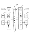
図1を参照して説明すれば、通報装置200は、通信端末11と共に、ターミナルアダプタ(以後、TAと略称する)12を介してIP電話網13に接続し、警報受信装置300はIP電話網13とターミナルアダプタ(TA)14を介して接続する。TA12、TA14それぞれは同一の装置である。この構成で、通報装置200、警報受信装置300および通信端末11、15とTA12,14との間はアナログ回線で接続される。TA12,14との間はIP電話網13を介してデジタル回線で接続される。
Referring to FIG. 1, the
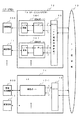
図2に示されるように、TA12は、複数の通信端末11それぞれを収容する端末ポート16−1、−2〜と、その複数の端末ポート16−1、−2〜をIP電話網13に接続するDSU(Digital Service Unit)18と、を有する。DSUは、加入者回線終端装置のことであり、ここでは、IP電話回線終端機能を有するものである。同様に、TA14は、複数の通信端末15それぞれを収容する端末ポート17−1、−2〜とその複数の端末ポート17−1、−2〜をIP電話網13に接続するDSU19とを有する。上述したように、TA12、14は同一構成であり、ここで同一の名称を付与されたものは符号が異なるが同一の構成及び機能を有する。
As shown in FIG. 2, TA 12 connects terminal ports 16-1 and −2 to accommodate a plurality of communication terminals 11 and the plurality of terminal ports 16-1 and −2 to IP telephone network 13. DSU (Digital Service Unit) 18. The DSU is a subscriber line terminating device, and here has an IP telephone line terminating function. Similarly, the
周知のように、端末ポートは2/4変換部(2線/4線変換回路)およびコーデック(アナログ/デジタル変換回路)を有し、2/4変換部の4線部分では、アナログ信号による送話路と受話路とが形成される。このため、送話路と受話路との間の漏話および2線/4線変換のためのハイブリッドトランスでの音声の回り込みなどが原因となり、エコーの発生を避けることはできない。 As is well known, the terminal port includes a 2/4 conversion unit (2-wire / 4-wire conversion circuit) and a codec (analog / digital conversion circuit). The 4-line portion of the 2/4 conversion unit transmits analog signals. A speech path and a reception path are formed. For this reason, the occurrence of echoes cannot be avoided due to the crosstalk between the transmission path and the reception path and the wraparound of the voice in the hybrid transformer for 2-line / 4-line conversion.
このようなエコーの発生を解決するためには漏話の低減または音声の回り込み除去が提案されている。漏話低減対策については例えば国際公開番号WO2004−110005号公報(特許文献3)が提案され、ハイブリッドトランスでの音声の回り込み除去については例えば特開2003−198433号公報(特許文献4)が提案されている。 In order to solve the occurrence of such echoes, it has been proposed to reduce crosstalk or eliminate speech wraparound. For example, International Publication No. WO2004-110005 (Patent Document 3) is proposed as a measure for reducing crosstalk, and for example, Japanese Unexamined Patent Application Publication No. 2003-198433 (Patent Document 4) is proposed as a method for removing speech wraparound in a hybrid transformer. Yes.
これら特許文献3〜4では、2線/4線変換回路のアナログ信号が伝送される4線部分で、受話路で受ける音声を分析してその結果を送話路に反映させることにより、送話路に音声が送出される際の受話路での音声による送話路への影響を低減させている。このような回路構成では、エコーキャンセラを備えないと、受話路の音声信号のレベルが大きな場合、その信号が送話路の信号に与える影響は大きい。特に、アナログ回線を用いて、警報となる非常用通報を音声信号で警報受信装置に送る場合、そのデータ情報がエコーにより崩れて異なる警報に形成されて警報受信装置に到達し、誤った緊急対策が講じられることになりかねない。
In these
解決しようとする課題は、アナログ回線での警報信号伝達の際に、発生元の通報装置が検出した警報を監視先の警報受信装置に確実に通知できる通報システムを提供することである。 The problem to be solved is to provide a notification system capable of reliably notifying an alarm receiving device as a monitoring destination of an alarm detected by an originating notification device when an alarm signal is transmitted through an analog line.
本発明は、複数の通信端末をアナログ回線で収容してデジタル回線と接続するターミナルアダプタを備え、当該ターミナルアダプタのアナログ回線に接続して発生元の通報装置が検出した警報を監視先の警報受信装置に確実に通知できることを目的としている。 The present invention includes a terminal adapter that accommodates a plurality of communication terminals by analog lines and connects to a digital line, and receives alarms detected by a reporting device that is connected to the analog line of the terminal adapter and received by a monitoring destination. The purpose is to be able to reliably notify the device.
そのため、本発明は、前記通報装置が、信号を送信する送信路回線となる第1の前記アナログ回線と、信号を受信する受信路回線となる第2の前記アナログ回線とのそれぞれを接続する一組の第1、第2の回線ポートと、発呼の際には前記第1、第2の回線ポートを用いて、予め記憶された互いに異なる宛先の第1、第2のアドレスそれぞれにより発呼する発信制御手段と、を有することを主要な特徴とする。 Therefore, according to the present invention, the notification device connects each of the first analog line serving as a transmission line for transmitting a signal and the second analog line serving as a reception line for receiving a signal. The first and second line ports of the set and the first and second line ports stored in advance using the first and second line ports when making a call The main feature is that it has a transmission control means.
このように、ターミナルアダプタで、音声信号の送信路回線と受信路回線とが別のアナログ回線に分離されている構成により、通報装置での送信路回線では、着呼側で接続される警報受信装置からの音声信号を受けることがないので、通報装置から可聴信号で送信される警報データへの漏話または回り込みによる阻害は発生しない。警報受信装置から送信の音声による情報も、同様に、受信路からの影響を受けることはない。特に、エコーキャンセラなどの阻害信号防止回路がないので、回路故障等で稼動できないというような状況の発生がない。 In this way, in the terminal adapter, the voice signal transmission line and the reception line are separated into separate analog lines, so that the alarm reception that is connected on the callee side in the transmission line in the reporting device Since no audio signal is received from the device, there is no obstruction caused by crosstalk or wraparound to alarm data transmitted as an audible signal from the reporting device. Similarly, information by voice transmitted from the alarm receiver is not affected by the receiving path. In particular, since there is no obstruction signal prevention circuit such as an echo canceller, there is no occurrence of a situation in which operation is not possible due to a circuit failure or the like.
一方、この通報装置に対向して接続される前記警報受信装置は、信号を受信する受信路回線となる第3の前記アナログ回線と信号を送信する送信路回線となる第4の前記アナログ回線とのそれぞれを接続する一組の第3、第4の回線ポートと、当該第3、第4の回線ポートに前記第1、第2のアドレスそれぞれを有し、当該第1、第2のアドレスで着呼を受けた際には、前記第3、第4の回線ポートに自己装置の受信路回線および送信路回線それぞれを接続して応答する着信制御手段と、を有する。その結果、当該第3、第4の回線ポートからの応答により前記通報装置の送信路回線に自己装置の受信路回線を、前記通報装置の受信路回線に自己装置の送信路回線を、それぞれ対応させて接続することとなる。 On the other hand, the alarm receiving device connected opposite to the notification device includes a third analog line serving as a reception path line for receiving signals and a fourth analog line serving as a transmission path line for transmitting signals. A pair of third and fourth line ports, and the third and fourth line ports respectively having the first and second addresses, and the first and second addresses When receiving an incoming call, there is an incoming call control means for responding by connecting the reception path line and the transmission path line of the own apparatus to the third and fourth line ports. As a result, a response from the third and fourth line ports corresponds to the transmission path line of the notification apparatus corresponding to the transmission path line of the notification apparatus and the transmission path line of the own apparatus to the reception path line of the notification apparatus, respectively. Will be connected.
また、前記通報装置と対向して接続される前記警報受信装置とのそれぞれは、複数組の回線ポートを備えて、その少なくともひとつを警報の伝達専用に用いることができる。したがって、警報データの伝達路と対話音声の伝達路とを別回線で形成できるので、警報データの伝達と共に、メッセージなどの音声情報の伝達が正確かつ容易に可能であり、特に緊急の警報を確実に伝達するには有効である。 Each of the alarm receivers connected to face the notification device includes a plurality of line ports, and at least one of them can be used exclusively for alarm transmission. Therefore, since the alarm data transmission path and the dialog voice transmission path can be formed on separate lines, it is possible to accurately and easily transmit voice information such as messages as well as alarm data. It is effective to communicate to.
本発明の通報システムは、通報装置とこの通報装置に接続される警報受信装置との間が所定の二つの宛先アドレスで二つのアナログ回線を接続し、一方の回線を送信路回線、他方の回線を受信路回線それぞれに設定する。そのため、アナログ回線を接続するターミナルアダプタの回線ポートでは、送信路回線として設定されたアナログ回線の送信路には送信の音声信号が送信されるが、この送信路回線の受信路には伝達される音声信号が存在しない。 In the notification system of the present invention, two analog lines are connected between a notification device and an alarm receiver connected to the notification device with two predetermined destination addresses, one line being a transmission line, and the other line. Is set for each receiving line. Therefore, in the line port of the terminal adapter that connects the analog line, a transmission voice signal is transmitted to the transmission path of the analog line set as the transmission path line, but is transmitted to the reception path of this transmission path line. There is no audio signal.
従って、送信路回線では、送信路に送出される音声信号は受信路からの漏話または回り込み信号による悪影響を受けることはない。更に、本発明によれば、IP電話網を経由するため各回線に必要とされる高価なエコーキャンセラを備えることなく、確実に警報を伝達することが可能となる。 Therefore, in the transmission path line, the audio signal sent to the transmission path is not adversely affected by crosstalk from the reception path or a sneak path signal. Furthermore, according to the present invention, it is possible to reliably transmit an alarm without providing an expensive echo canceller required for each line because it passes through the IP telephone network.
発生元の通報装置が検出した警報を監視先の警報受信装置に確実に通知できる通報システムを提供するという目的を、二つを一組とするアナログ回線を通報装置と警報受信装置との間で接続し、一方の回線を音声信号の送信路回線、他方の回線を受信路回線に設定し、送信路回線における端末ポートで回線の受信路での音声信号伝送を排除することにより、故障などで警報伝達の障害となるエコーキャンセラなどの回り込み防止回路を配備することなく、送信路回線における受信路から送信路への漏話および回り込み信号の排除を実現した。 The purpose of providing a notification system that can reliably notify the alarm received by the reporting device of the source to the alarm receiving device of the monitoring destination. By connecting, setting one line as a voice signal transmission line and the other line as a reception line, and eliminating the transmission of voice signals on the line reception path at the terminal port in the transmission line, We realized crosstalk from the reception path to the transmission path in the transmission path and the elimination of the sneak signal without deploying an anti-wraparound circuit such as an echo canceller that would interfere with alarm transmission.
本発明として、具体的には、複数の通信端末をアナログ回線で収容してデジタル回線と接続するターミナルアダプタを備え、当該ターミナルアダプタのアナログ回線に接続して警報を発生元の通報装置から監視先の警報受信装置に通知する際に、二つを一組とする回線ポートを前記通報装置に、かつ、相互に異なる二つの宛先アドレスそれぞれを有する二つを一組とする回線ポートを前記警報受信装置に、それぞれ備えている。そして、前記通報装置が一つの発呼を検知した際に二つの回線ポートそれぞれから、前記二つの宛先アドレスで自動発信して前記警報受信装置の二つの前記回線ポートそれぞれに接続させる。次いで、所定の手順により、接続された二つの回線それぞれで、一方の接続回線を音声信号の送信路回線に形成するとともに、他方の接続回線を音声信号の受信路回線に形成することとした。 Specifically, the present invention includes a terminal adapter that accommodates a plurality of communication terminals by analog lines and connects to a digital line, and connects to the analog line of the terminal adapter to send an alarm from a notification device that generates an alarm to a monitoring destination When the alarm receiving device is notified, the two alarm ports are received by the notification device and the two port ports having two different destination addresses are received by the alarm receiver. Each device is equipped. Then, when the notification device detects one call, the two line ports automatically make calls from the two destination addresses and connect to the two line ports of the alarm receiver. Next, in accordance with a predetermined procedure, one of the two connected lines is formed as a voice signal transmission line and the other connection line is formed as a voice signal reception line.
ここでいう送信路回線および受信路回線それぞれは、ターミナルアダプタの二つの端末ポートそれぞれに接続する一つずつのアナログ回線で構成されており、アナログ信号の送信路および受信路、または通話信号の場合の送話路および受話路となる。 Each of the transmission path line and reception path line here consists of one analog line connected to each of the two terminal ports of the terminal adapter. In the case of an analog signal transmission path and reception path, or a speech signal This is the transmission path and reception path.
図面では本発明に係る機能ブロックを優先して示しており、装置で必須の機能でも省略されているものがある。図示される機能ブロックの分離併合、手順の入替えなどによる変更は、本願発明の趣旨および機能を満たすものであれば自由であり、以下の説明が本発明を限定するものではない。 In the drawings, functional blocks according to the present invention are preferentially shown, and some functions essential to the apparatus are omitted. Modifications by separating and merging the functional blocks shown in the figure, changing the procedure, and the like are free as long as they satisfy the spirit and function of the present invention, and the following description does not limit the present invention.
本発明の実施例1について図3から図7までを参照して説明する。 A first embodiment of the present invention will be described with reference to FIGS.
図3は、本発明による通報システムの通報装置20を、一つの通信端末としてみなし、通信端末11同様、ターミナルアダプタ(以後、TAと略称する)12を介してIP電話網13に接続する一実施例をブロックで示す説明図である。通報装置20は、一つの通信端末ではあるが、TA12の二つの端末ポートを占有する。ここでの通信端末11は、例えばIP電話機である。TA12は端末ポート16−1、−2、〜−NおよびDSU(Digital Service Unit:加入者回線終端装置)18を有する。IP電話網13は、インターネットを含むネットワークを利用した電話網である。
FIG. 3 shows an embodiment in which the
TA12の端末ポート16−のそれぞれは周知のように、2/4変換部(2線/4線変換回路)およびコーデック(アナログ/デジタル変換回路)を有し、2/4変換部の4線部分では、アナログ信号による送信路と受信路とが形成される。DSU18は、ここではIP電話回線終端部であり、一方で端末ポート16−1、−2、〜−Nとアナログから変換されたデジタル信号を授受し、他方でIP電話網13と接続してデジタル信号を授受する。したがって、TA12は周知の単純なターミナルアダプタでよい。
As is well known, each of the terminal ports 16- of the
図示されるように、通報装置20はアナログ端末であり、音声信号に対して、自己の送信路および受信路それぞれを二つのアナログ回線に接続する。二つの回線は、それぞれが通信回線であり、一方を送信路回線、他方を受信路回線としてのみに使用し、TA12の端末ポート16−1、−2それぞれに接続される。従って、音声信号は、端末ポート16−1を介して送信され、端末ポート16−2を介して受信される。同様に、接続相手先装置である警報受信装置も、後述するように送信路および受信路それぞれを二つのアナログ回線に接続しており、通報装置20がこの接続相手先装置と正常に接続されているものであれば、アナログの警報を発信中において端末ポート16−1の回線では受信路からの音声信号は伝送されない。
As shown in the figure, the reporting
従って、受信側端末ポートで送信信号の漏話または回り込みがあったとしても、送信側端末ポートに戻ってきた際には低雑音として受信するのみである。それ故、通報装置20から送信するアナログ信号に悪影響はない。一方、端末ポート16−2は接続相手先装置から受信路回線を介して受ける例えば応答信号、確認信号などの返信による受信信号のみを通報装置20へ伝送する。本実施例での接続相手先装置は警報受信装置であり、詳細は後に説明する。
Therefore, even if there is crosstalk or wraparound of the transmission signal at the receiving terminal port, it is only received as low noise when returning to the transmitting terminal port. Therefore, there is no adverse effect on the analog signal transmitted from the reporting
次に、図4に図3を併せ参照して本発明に係る通報装置20について説明する。
Next, the
図4に示される通報装置20は、一方に警報センサ1、非常ボタン2、非常用電話機3などを、他方に上記TA12と接続する二つの電話回線を、それぞれ接続し、警報検知部21、発信制御部22、送受信回線自動発信部23、S回線ポート24、R回線ポート25、電話機ポート26および2/4変換部27を有する。
The
警報センサ1は、例えば火災警報などの自動センサ、非常ボタン2も例えば火災警報などの押しボタンであって、それぞれ複数個および複数種類であってもよい。非常用電話機3も、警報センサ1および非常ボタン2を搭載されてもよいが、警報受信先と接続の際に警報情報の送信および対話を可能とするものである。
The
警報検知部21は、警報センサ1、非常ボタン2などと接続し、所定の信号を受けて警報を検知した際、警報種別、警報位置などのデータ情報をアナログ信号に形成して発信制御部22に通知する。このアナログ信号は、例えば押しボタン(PB)ダイヤルで使用される音声周波数の組合せによる。発信制御部22は、警報検知部21または電話機ポート26から警報情報を受付けした場合、および電話機ポート26から通常の発呼を受付けした場合、何れの場合も、送受信回線自動発信部23に予め記憶された二つの宛先アドレスを取り出し、それぞれ対応するS回線ポート24およびR回線ポート25から電話回線に発呼し、自動ダイヤル発信する。この宛先アドレスは、例えば、アドレス「A」が送信路回線に、アドレス「B」が受信路回線にそれぞれ送信されるものとする。
The
従って、発信制御部22は、通報装置20が警報検知部21から発呼の際、S回線ポート24を介してアドレス「A」で送信路回線に、R回線ポート25を介してアドレス「B」で受信路回線にそれぞれ自動的にダイヤル発信する。その結果、各回線で呼出音を、次いで応答信号をそれぞれ受付けする。この状態では、二つの電話回線が、送信路回線および受信路回線としてS回線ポート24およびR回線ポート25それぞれに接続されている。発信制御部22による発呼機能およびその動作手順は周知のものでよく、これらの接続制御のための信号授受はそのシステムを限定するものではない。ここで、接続相手先との送受話路確立を確認する送受信確認機能が機能するものとする。その具体的構成は、周知の何れの技術でもよい。
Therefore, when the
例えば、送受信路回線が接続済み状態にあるので、発信制御部22は、その接続確認のため、確認信号をS回線ポート24の送信路回線から送信し、S回線ポート24およびR回線ポート25の信号受信を監視する。相手先では、その確認信号を折り返しこの送信路回線ではなく受信路回線に返信することにより、R回線ポート25の受信路回線のみで受付けすることにより、正常の送受信路回線接続を確認することができる。
For example, since the transmission / reception path line is in a connected state, the
送受信回線自動発信部23には、S回線ポート24およびR回線ポート25それぞれに対応する二つの宛先アドレス、本実施例ではアドレス「A」およびアドレス「B」が予め記憶されている。このアドレスは、電話網を介して接続される相手先の警報受信装置が有する二つの電話回線用ポートそれぞれに付与されているものである。また、上記警報種別に警報データが含まれることにより、警報受信装置で識別され、受信側で異なった警報を発生することができる。警報種別に対応する複数の警報受信装置が設けられる場合、警報受信装置それぞれの電話回線用ポートに付与される二つの宛先アドレスが更に追加されて予め記憶されることになる。本実施例では一つの警報受信装置に接続されるものとする。
In the transmission / reception line
S回線ポート24およびR回線ポート25それぞれは、通常の2線式電話回線と接続するものであり、一方では発信制御部22、他方ではTA12の二つの端末ポートそれぞれに対して接続される。従って、上述の接続制御が終了して接続相手先と電話回線の接続が完了した時点では、S回線ポート24は警報信号等の送信路、R回線ポート25は接続先からの信号受信路、それぞれに限定して用いられる。その結果、図3で示されるように、S回線ポート24から警報信号等の送出がある場合、端末ポート16−1における2/4変換部では受信信号がないので漏話および回り込みによる警報信号の歪は発生しない。
Each of the
電話機ポート26は非常用電話機3を接続して、非常用電話機3との間の制御信号は発信制御部22と授受し、音声信号は2/4変換部27と授受する。すなわち、非常用電話機3からの所定のボタンによる警報は発信制御部22に直接伝達され、上記非常ボタン同様に接続処理される。非常用電話機3からの発呼の場合も同様の手順で所定の警報受信装置宛てに自動接続されるが、警報種別には電話機呼出し情報が含まれる。
The
2/4変換部27は電話機ポート26との間で音声信号を授受し、電話機ポート26からの音声信号は発信制御部22およびS回線ポート24を介して送信路回線に送出し、電話機ポート26への音声信号は受信路回線からR回線ポート25を介して受付けする。
The 2/4
次に、図5および図6を参照して警報受信側のシステムについて説明する。 Next, the system on the alarm receiving side will be described with reference to FIGS.
図5は、本発明による通報システムの警報受信装置30を、一つの通信端末としてみなし、通信端末15同様、ターミナルアダプタ(以後、TAと略称する)14を介してIP電話網13に接続する一実施例をブロックで示す説明図である。警報受信装置30は、一つの通信端末ではあるが、TA14に対しては二つの端末ポートを占有する。TA14は上述のTA12と同一構成でよい。従って、TA14は端末ポート17−1、−2、〜―NおよびDSU19を有し、その構成は、上述の端末ポート16−、DSU18のそれぞれと同一である。また、通信端末15も通信端末11と同一でよい。
FIG. 5 shows that the
TA14の端末ポート17−のそれぞれは周知のように、2/4変換部およびコーデックを有し、2/4変換部の4線部分では、アナログ信号による送信路と受信路とが形成される。DSU19は、ここでは、IP電話回線終端部であり、一方で端末ポート17−1、−2、〜−Nとアナログから変換されたデジタル信号を授受し、他方でIP電話網13と接続してデジタル信号を授受する。ここで、上述の通報装置20が警報受信装置30に正常に接続するため、端末ポート17−1、−2にはアドレス「A」、「B」のそれぞれが予め付与されているものとする。
As is well known, each of the terminal ports 17- of the
図示される警報受信装置30はアナログ端末であり、音声信号に対して、自己の受信路および送信路それぞれを二つのアナログ回線に接続する。二つの回線は、それぞれが通信回線であり、一方を受信路回線、他方を送信路回線としてのみに使用し、TA14の端末ポート17−1、−2それぞれに接続される。従って、警報受信装置30での音声信号は、端末ポート17−1を介して受付けされ、端末ポート17−2を介して送出される。上述のように接続相手先装置である通報装置が送信路および受信路それぞれを二つのアナログ回線に接続しているので、接続相手先装置同士が正常に接続されているものであれば、アナログの警報を送信中において端末ポート17−1の回線には警報受信装置30からの送信信号は存在しない。あるとしても端末ポート17−1の回線の受信路からの音声信号の漏話および回り込みのみである。したがって、通報装置における送信路への漏話および回り込みは確実に回避される。
The illustrated
次に、図6に図5を併せ参照して本発明に係る警報受信装置30について説明する。
Next, the
図6に示されるように、警報受信装置30は、一方に上記TA14と接続する二つの電話回線を、他方に警報表示器4、電話機5などを、それぞれ接続し、R回線ポート31、S回線ポート32、着信制御部33、警報通知部34、電話機ポート35および2/4変換部36を有する。
As shown in FIG. 6, the
警報表示器4は、警報受信装置30から火災警報などの通知を受付けして可聴および可視による警報を発生する。一つの警報表示器4で、受付けの警報データに含まれる警報種別に従って警報の表示を切替えすることができる。また、警報種別に基づく複数の警報表示器4を備えて警報を発生するとしてもよい。電話機5は、電話機呼出し情報による警報種別で呼び出され、音声メッセージによる警報を受信して受話器またはスピーカで聴取できる。また、相手先の非常用電話機と接続して対話することもできる。
The
R回線ポート31は、通常の2線式電話回線と接続するものであり、一方では着信制御部33、他方ではTA14の端末ポートに対して接続される。S回線ポート32は、通常の2線式電話回線と接続するものであり、一方では2/4変換部36および着信制御部33、他方ではTA14の端末ポートに対して接続される。従って、着信制御部33による接続制御が終了して接続相手先と電話回線の接続が完了した時点では、R回線ポート31は警報信号等の受信路、S回線ポート32は接続先への信号送出路、それぞれに限定して用いられる。その結果、図5で示されるように、S回線ポート32へ音声信号等の送出がある場合でも、端末ポート17−1における2/4変換部とは切り離されているので、漏話および回り込みによる警報信号への悪影響は回避される。
The R line port 31 is connected to a normal two-wire telephone line, and is connected to the incoming call control unit 33 on the one hand and the terminal port of the
着信制御部33が、警報を受付けする際、R回線ポート31およびS回線ポート32の両者から呼出しを受け、正常着信に応答することにより、警報受信装置30は上述した通報装置20と二つの電話回線で接続される。着信制御部33は警報データとして通報装置20から警報種別を受付けするので、その警報種別に対応する警報表示器4または電話機5を呼出しして接続すると共に、警報種別を送出して警報種別に対応する警報を表示させる。すなわち、着信制御部33は、警報表示器4に対しては警報通知部34を介して、また電話機5に対しては電話機ポート35を介して、それぞれ警報を送出する。
When the incoming call control unit 33 accepts an alarm, it receives a call from both the R line port 31 and the S line port 32 and responds to a normal incoming call, whereby the
警報通知部34は、一方を着信制御部33、他方を警報表示器4それぞれに接続し、着信制御部33から着信を受付けした際、受付けの警報種別で警報表示器4に可聴・可視表示する。一つの警報表示器4が図示されているが、警報通知部34が警報種別に基づいて複数の警報表示器に分配してもよい。また、警報種別に基づいて複数の警報通知部34を配備することもできる。この場合、着信制御部33が警報種別に基づいて一つの警報通知部34を選択し接続する。
The
電話機ポート35は、一方に電話機5、他方に着信制御部33および2/4変換部36それぞれを接続し、着信制御部33の制御で電話機5を呼出しして電話機5の通話回線を2/4変換部36に接続する。2/4変換部36は、電話機5からの送話信号をS回線ポート32へ送り、R回線ポート31から受付けの受話信号を電話機5へ送る。
The telephone port 35 is connected to the
次に、図7に図3から図6までを併せ参照して、通報装置20での警報発生から、警報受信装置30で警報表示するまでの主要手順について説明する。
Next, with reference to FIGS. 3 to 6 together with FIG. 7, the main procedure from the generation of an alarm in the
まず、通報装置20で警報を検知した場合、通報装置20は二つの電話回線に発呼し、所定の二つのアドレス「A,B」それぞれにより自動ダイヤル発信してIP電話網13に呼設定要求(手順S1)する。IP電話網13では、その呼設定要求に基づき警報受信装置30の二つの電話回線それぞれで呼設定要求し呼出し信号で呼出しすると共に呼出し音(RBT)を通報装置20に返送(手順S2)する。呼出し信号を受付けした警報受信装置30では、その着呼に応答し、応答信号を送出(手順S3)する。IP電話網13は、この応答信号を二つの回線それぞれで通報装置20に転送した後、その二つの通信路を形成すると共に呼出し音の送出を停止(手順S4)する。その結果、通報装置20と警報受信装置30との間は二つの通信路が形成される。
First, when the
ここで、通報装置20は、警報受信装置30との間で送信路と受信路との区別を確認するため、確認信号を送信路回線に送出(手順S5)し、警報受信装置30ではそれを正常受信した際にその応答信号を送信路回線から送出(手順S6)する。通報装置20は、その応答信号を自己の受信路回線で受付けすることにより両者間での送受信路正常形成を確認する。この手順S5の確認信号を警報信号そのものとすることができる。この場合、手順が正常に進めば、警報の伝達が早いので望ましい。
Here, in order to confirm the distinction between the transmission path and the reception path with the
この応答信号の正常受付けにより、通報装置20は、検知された情報に基づく警報データを、通報装置20の送信路回線から発信(手順S7)し、警報受信装置30では受信路回線で着信するので、その正常受信を確認(手順S8)する。警報受信装置30は、この警報の正常受信を確認して警報を表示すると共に、送信路回線から確認信号を発信(手順S9)する。
As the response signal is normally received, the
上記手順S7以降では、通報装置20と警報受信装置30との間に二つの回線それぞれを用いて送受信を実行できる。したがって、電話機3,5同士であれば対話が可能である。
In step S7 and subsequent steps, transmission / reception can be performed between the
通信の終了においては、通報装置20が受信側から警報正常受信の確認信号を受付けした際に所定の回線切断処理を実行(手順S10)する。例えば、IP電話網13では、通報装置20からの切断信号を受付けして警報受信装置30へ転送すると共に、通報装置20に解放信号を返信して処理を終了させ復旧(手順S11)する。警報受信装置30は、切断信号を受付けしてIP電話網13に解放信号を返信して復旧(手順S12)する。
At the end of communication, when the
上述の手順S5,S6の確認手順は、その時点で、送信路回線と受信路回線とが独立して呼接続とその応答による制御を実施しているので、例えば、通報装置20が、所定の制御手順を用いて、送信路回線および受信路回線に確認信号を送り、送信路回線と受信路回線とのそれぞれでその返答を待つこともできる。この場合、警報受信装置30は各回線ポートで確認信号を受付けしたことを認識し、応答信号を返送する。通報装置20は所定時間内に所定の応答信号を受付けしたことにより正常の警報転送路の成立を確認とする。
In the confirmation procedure of the above-described steps S5 and S6, since the transmission path line and the reception path line are independently controlled by the call connection and the response at that time, for example, the
上述の場合、警報が所定の警報受信装置30に確実に通知して確実に表示された場合には、直ちに接続を復旧している。しかし、警報受信装置側では、その警報表示を残すことが望ましい。また、通報装置20は、正常手順のみで進め、異常の際のみに転送異常を警報受信装置30に通知するかまたは警報受信装置30から通知を受けることが、警報通知の迅速化のために望ましい。
In the case described above, when the alarm is surely notified to the
また、通報装置で、警報により自動発呼され、受信側から正常受信の確認応答があった場合に、受信側からの解放指示を受けない限り、IP電話網を介して接続された通信回線を切断せずに保留することもできる。この場合、非常用電話機を受信側から呼出しすることが可能であり、電話機による関係者の対話を可能にする。 In addition, when a notification device automatically calls an alarm and receives a normal reception confirmation response from the receiving side, the communication line connected via the IP telephone network is not connected unless a release instruction is received from the receiving side. You can also hold without disconnecting. In this case, it is possible to call the emergency telephone from the receiving side, and to allow the parties to interact with the telephone.
このような構成を採用したので、アナログ回線を接続するターミナルアダプタの回線ポートでは、送信路回線として設定されたアナログ回線の受信路には伝達される音声信号が存在しないので、送信路から送信の音声信号に受信路からの漏話信号または回り込み信号による悪影響を受けることはない。従って、IP電話網を経由するために必要とされる各回線での高価なエコーキャンセラを備えることなく、確実に警報を伝達することが可能となる。 Since such a configuration is adopted, in the line port of the terminal adapter to which the analog line is connected, there is no voice signal transmitted in the reception path of the analog line set as the transmission path line. The voice signal is not adversely affected by the crosstalk signal or the sneak signal from the receiving path. Therefore, it is possible to reliably transmit an alarm without providing an expensive echo canceller on each line required for passing through the IP telephone network.
本発明の実施例2について図8を参照して説明する。 A second embodiment of the present invention will be described with reference to FIG.
図8の実施例は、通報装置と警報受信装置との間で電話機同士が対話中に、警報が発生した場合、警報の伝達に対話による影響を排除するものである。すなわち、上述の実施例で警報を伝達する二つのアナログ回線に加え、電話機同士が対話できる二つのアナログ回線を備えている。 The embodiment of FIG. 8 eliminates the influence of dialogue on the transmission of an alarm when an alarm is generated while the telephones are interacting with each other between the reporting device and the alarm receiving device. That is, in addition to the two analog lines for transmitting an alarm in the above-described embodiment, two analog lines through which telephones can communicate with each other are provided.
図8で上述の実施例と相違することは、通報装置40と警報受信装置60とにある。他のシステム構成は同一であり、同一機能を有するのでその説明は省略する。
8 differs from the above-described embodiment in the
図示される通報装置40は、PB信号送受信部41および音声信号送受信部42を備えると共に、TA12の4つの端末ポート16−1〜−4を占有して接続する。PB信号送受信部41は二つの端末ポート16−1、−2、音声信号送受信部42は二つの端末ポート16−3、−4、それぞれと接続し、二つの回線それぞれを送信路および受信路として用いる。
The illustrated
図示される警報受信装置50は、PB信号送受信部51および音声信号送受信部52を備えると共に、TA14の4つの端末ポートを占有して接続する。PB信号送受信部51は二つの端末ポート、音声信号送受信部52は二つの端末ポート、それぞれと接続し、二つの回線それぞれを送信路および受信路として用いる。
The illustrated
PB信号送受信部41,51は上述の実施例と同等の機能を有し警報信号の授受を行なうものである。音声信号送受信部42,52は電話機同士または電話機同等装置同士で音声信号の送受信を行なうものである。したがって、音声信号送受信部42,52のため、通報装置40に一つの警報受信装置50に対応する二つのアドレスを予め記憶し、警報受信装置50にも一つの通報装置40に対応する二つのアドレスを予め記憶している。そして、一つの発呼の際に二つの回線それぞれに異なるアドレスでダイヤル発信することとなる。
The PB signal transmission /
このような構成を有するので、警報を可聴周波数によるPB信号(押しボタンダイヤル用の多周波信号)で伝送中に電話機での対話開始、または、電話機での対話中に警報の発生、などの場合、送信受信の回線のみならず、警報と対話との相互の通信回線が別回線のため、特に、警報に対する障害発生を回避できるので、対話によるメッセージ伝達の可能性も加え、確実な警報伝達を可能にしている。 Since it has such a configuration, when an alarm is transmitted as a PB signal (multi-frequency signal for push button dial) at an audible frequency, a dialog starts on the telephone, or an alarm is generated during a dialog on the telephone, etc. In addition to the transmission / reception line, the mutual communication line between the alarm and the dialog is a separate line, so it is possible to avoid the occurrence of a failure especially for the alarm. It is possible.
すなわち、通報装置と対向して接続される警報受信装置とのそれぞれは、複数組の回線ポートを備えているので、そのうちの少なくとも一つを警報の伝達専用に用いることができる。このため、警報データの伝達路と対話音声の伝達路とを別回線で形成できる。従って、警報データの伝達と共に、メッセージなどの音声情報の伝達が正確かつ容易に可能であり、特に緊急の警報を確実に伝達するには有効である。 That is, since each of the alarm receivers connected to face the notification device includes a plurality of sets of line ports, at least one of them can be used exclusively for alarm transmission. For this reason, the transmission path for alarm data and the transmission path for dialogue voice can be formed on separate lines. Therefore, it is possible to accurately and easily transmit voice information such as a message together with transmission of alarm data, and it is particularly effective for reliably transmitting an emergency alarm.
上記説明では、ダイヤル信号の利用が可能なため警報信号をPB信号としたが、通報装置と警報受信装置との間で特有の信号が設定されるならば、PB信号に限定されることなく、他の可聴周波数を用いた単独および組合せによる信号でもよい。また、警報信号は複数種類の伝送が可能であり、警報受信装置で警報の種別により異なる警報の表示が可能である。警報受信装置は警報受信システムとして異なる警報対応に設けることもできる。複数の警報受信装置に対しては、警報装置に自動ダイヤル発信のための複数組のアドレスを記憶することになる。また、通報装置側で複数装置を設ける場合、警報受信装置でも自動ダイヤル発信のための複数組のアドレスを記憶することになろう。 In the above description, since the dial signal can be used, the alarm signal is the PB signal. However, if a specific signal is set between the notification device and the alarm receiver, the alarm signal is not limited to the PB signal. It may be a single or combined signal using other audible frequencies. Also, a plurality of types of alarm signals can be transmitted, and different alarms can be displayed depending on the type of alarm in the alarm receiver. The alarm receiver can be provided for different alarms as an alarm receiver system. For a plurality of alarm receiving devices, a plurality of sets of addresses for automatic dialing are stored in the alarm device. When a plurality of devices are provided on the notification device side, a plurality of sets of addresses for automatic dial transmission will be stored in the alarm receiving device.
送受信路を形成する2線のアナログ回線を例えばデジタル回線のように4線の送受信分離回路に変換する伝送システムの場合、二組の2線のアナログ回線それぞれを独立した送信路回線および受信路回線として用いることにより、容易かつ安全に、受信路から送信路へのアナログ信号の漏話および回り込みを回避できるので、警報に限定されることなく、緊急かつ重要な信号の確実な伝送を必要とする用途に有効に適用可能である。 In the case of a transmission system that converts a two-line analog line forming a transmission / reception path into a four-line transmission / reception separation circuit such as a digital line, for example, two sets of two-line analog lines are respectively independent transmission path lines and reception path lines. As an analog signal, it is possible to avoid crosstalk and wraparound of analog signals from the reception path to the transmission path easily and safely, so that applications that require reliable transmission of urgent and important signals are not limited to alarms. It can be effectively applied to.
1 警報センサ
2 非常ボタン
3 非常用電話機
4 警報表示器
5 電話機
11、15 通信端末
12、14 TA
13 IP電話網
16、16−1〜−5、16−N、17、17−1〜−3、17−N 端末ポート
18、19 DSU
20、40 通報装置
21 警報検知部
22 発信制御部
23 送受信回線自動発信部
24、32 S回線ポート
25、31 R回線ポート
26、35 電話機ポート
27、36 2/4変換部
30、50 警報受信装置
33 着信制御部
34 警報通知部
41、51 PB信号送受信部
42、52 音声信号送受信部
DESCRIPTION OF
13 IP telephone network 16, 16-1 to -5, 16-N, 17, 17-1 to -3, 17-
20, 40
Claims (9)
前記通報装置が、信号を送信する送信路回線となる第1の前記アナログ回線と信号を受信する受信路回線となる第2の前記アナログ回線とのそれぞれを接続する一組の第1、第2の回線ポートと、発呼の際には前記第1、第2の回線ポートを用いて、予め記憶された互いに異なる宛先の第1、第2のアドレスそれぞれにより発呼する発信制御手段と、を有する
ことを特徴とする通報システム。 A reporting system that includes a terminal adapter that accommodates a plurality of communication terminals on an analog line and connects to the digital line, and that connects to the analog line of the terminal adapter to notify the alarm from the reporting device that issued the alarm to the monitoring device that receives the alarm In
The notification device connects a first pair of first and second analog lines that respectively connect the first analog line serving as a transmission line for transmitting signals and the second analog line serving as a reception line for receiving signals. And a call control means for making a call with each of the first and second addresses of different destinations stored in advance using the first and second line ports when making a call, A notification system characterized by having.
前記警報受信装置は、信号の送信路回線となる第3の前記アナログ回線と信号の受信路回線となる第4の前記アナログ回線とのそれぞれを接続する一組の第3、第4の回線ポートと、当該第3、第4の回線ポートに第1、第2のアドレスそれぞれを有し、当該第1、第2のアドレスで着呼を受けた際には、前記第3、第4の回線ポートに自己装置の受信路回線および送信路回線それぞれを対応させて接続し応答する着信制御手段と、を有し、
当該第3、第4の回線ポートからの応答により通報装置の送信路回線に自己装置の受信路回線を、前記通報装置の受信路回線に自己装置の送信路回線を、それぞれ対応させて接続することを特徴とする通報システム。 A reporting system that includes a terminal adapter that accommodates a plurality of communication terminals on an analog line and connects to the digital line, and that connects to the analog line of the terminal adapter to notify the alarm from the reporting device that issued the alarm to the monitoring device that receives the alarm In
The alarm receiving device is a set of third and fourth line ports for connecting the third analog line serving as a signal transmission line and the fourth analog line serving as a signal reception line. And the third and fourth line ports have first and second addresses, respectively, and when the first and second addresses are received, the third and fourth lines An incoming call control means for connecting and responding to the port corresponding to the reception path line and the transmission path line of the own device,
In response to the responses from the third and fourth line ports, the own device's reception path line is connected to the notification apparatus's transmission path line, and the own apparatus's transmission path line is connected to the notification apparatus's reception path line. A notification system characterized by this.
前記通報装置が一つの発呼を検知した際に二つを一組とする回線ポートそれぞれから、前記二つ一組の宛先アドレスで自動発信して前記警報受信装置の二つ一組の前記回線ポートそれぞれに接続させる手順と、所定の手順により、接続された二つの回線それぞれで、一方の接続回線を音声信号の送信路回線に形成するとともに、他方の接続回線を音声信号の受信路回線に形成する手順とを有することを特徴とする通報方法。 In a method of providing a terminal adapter for accommodating a plurality of communication terminals by analog lines and connecting to a digital line, connecting to the analog line of the terminal adapter and notifying an alarm from a notification device of a generation source to an alarm reception device of a monitoring destination One set or a plurality of sets of line ports having two sets as one set are connected to the notification device, and one set or a plurality of sets of line ports having two sets each having two different destination addresses are set. In each of the alarm receivers,
When the notification device detects one call, each of the line ports that make two sets automatically sends out the two sets of destination addresses, and the two sets of lines of the alarm receiving device. According to the procedure for connecting to each port and the predetermined procedure, one of the two connected lines is formed as a voice signal transmission line and the other connection line is used as a voice signal reception line. And a forming method.
Priority Applications (1)
| Application Number | Priority Date | Filing Date | Title |
|---|---|---|---|
| JP2008193127A JP5110532B2 (en) | 2008-07-28 | 2008-07-28 | Reporting system |
Applications Claiming Priority (1)
| Application Number | Priority Date | Filing Date | Title |
|---|---|---|---|
| JP2008193127A JP5110532B2 (en) | 2008-07-28 | 2008-07-28 | Reporting system |
Publications (2)
| Publication Number | Publication Date |
|---|---|
| JP2010034731A true JP2010034731A (en) | 2010-02-12 |
| JP5110532B2 JP5110532B2 (en) | 2012-12-26 |
Family
ID=41738740
Family Applications (1)
| Application Number | Title | Priority Date | Filing Date |
|---|---|---|---|
| JP2008193127A Active JP5110532B2 (en) | 2008-07-28 | 2008-07-28 | Reporting system |
Country Status (1)
| Country | Link |
|---|---|
| JP (1) | JP5110532B2 (en) |
Citations (5)
| Publication number | Priority date | Publication date | Assignee | Title |
|---|---|---|---|---|
| JPS5459005A (en) * | 1977-10-19 | 1979-05-12 | Omron Tateisi Electronics Co | Data communication method |
| JPH06350728A (en) * | 1993-06-10 | 1994-12-22 | Rinnai Corp | Automatic reporting device |
| JPH11205479A (en) * | 1998-01-19 | 1999-07-30 | Yazaki Corp | Data transmitter-receiver in centralized monitoring system |
| JP2002111889A (en) * | 2000-09-29 | 2002-04-12 | Nec Infrontia Corp | Report system and terminal adapter |
| JP2002251676A (en) * | 2001-02-22 | 2002-09-06 | Hochiki Corp | Disaster preventing monitoring facility |
-
2008
- 2008-07-28 JP JP2008193127A patent/JP5110532B2/en active Active
Patent Citations (5)
| Publication number | Priority date | Publication date | Assignee | Title |
|---|---|---|---|---|
| JPS5459005A (en) * | 1977-10-19 | 1979-05-12 | Omron Tateisi Electronics Co | Data communication method |
| JPH06350728A (en) * | 1993-06-10 | 1994-12-22 | Rinnai Corp | Automatic reporting device |
| JPH11205479A (en) * | 1998-01-19 | 1999-07-30 | Yazaki Corp | Data transmitter-receiver in centralized monitoring system |
| JP2002111889A (en) * | 2000-09-29 | 2002-04-12 | Nec Infrontia Corp | Report system and terminal adapter |
| JP2002251676A (en) * | 2001-02-22 | 2002-09-06 | Hochiki Corp | Disaster preventing monitoring facility |
Also Published As
| Publication number | Publication date |
|---|---|
| JP5110532B2 (en) | 2012-12-26 |
Similar Documents
| Publication | Publication Date | Title |
|---|---|---|
| US8391277B2 (en) | Interoperability of legacy alarm system | |
| JP5110532B2 (en) | Reporting system | |
| JPS628061B2 (en) | ||
| JP7275867B2 (en) | emergency call device | |
| JP4941739B2 (en) | Reporting method and reporting device using the method | |
| JP3749085B2 (en) | Telephone equipment | |
| JPS5844850A (en) | Line switching device | |
| JP2514470B2 (en) | Cordless telephone equipment | |
| JP2513432Y2 (en) | Telephone device power failure switching circuit | |
| JP3708999B2 (en) | Telephone control system | |
| JP4158257B2 (en) | Communication terminal device | |
| JPH10210185A (en) | Notifying device | |
| JPH02194764A (en) | Remote supervisory equipment | |
| JP2000354114A (en) | Communication equipment | |
| JPH10191015A (en) | Telephone set system with error dial informing and data transfer functions | |
| JP2001177666A (en) | Communication equipment | |
| JP2002325148A (en) | Device for preventing wrongly arrived incoming call | |
| JP2019083464A (en) | Home gateway device, number display compatible detection method, and number display compatible detection program | |
| JPH1169005A (en) | Terminal adapter | |
| JPH09326885A (en) | Terminal network controller | |
| JPH03102962A (en) | Facsimile equipment | |
| JPH08111716A (en) | Key telephone system | |
| JPH11346252A (en) | Communication terminal | |
| JPS60226265A (en) | Incoming and outgoing collision prevention system of interior equipment | |
| JPH08335980A (en) | Communication terminating system |
Legal Events
| Date | Code | Title | Description |
|---|---|---|---|
| A621 | Written request for application examination |
Free format text: JAPANESE INTERMEDIATE CODE: A621 Effective date: 20100915 |
|
| A977 | Report on retrieval |
Free format text: JAPANESE INTERMEDIATE CODE: A971007 Effective date: 20120327 |
|
| A131 | Notification of reasons for refusal |
Free format text: JAPANESE INTERMEDIATE CODE: A131 Effective date: 20120613 |
|
| A521 | Written amendment |
Free format text: JAPANESE INTERMEDIATE CODE: A523 Effective date: 20120801 |
|
| TRDD | Decision of grant or rejection written | ||
| A01 | Written decision to grant a patent or to grant a registration (utility model) |
Free format text: JAPANESE INTERMEDIATE CODE: A01 Effective date: 20120912 |
|
| A01 | Written decision to grant a patent or to grant a registration (utility model) |
Free format text: JAPANESE INTERMEDIATE CODE: A01 |
|
| A61 | First payment of annual fees (during grant procedure) |
Free format text: JAPANESE INTERMEDIATE CODE: A61 Effective date: 20121002 |
|
| FPAY | Renewal fee payment (event date is renewal date of database) |
Free format text: PAYMENT UNTIL: 20151019 Year of fee payment: 3 |
|
| R150 | Certificate of patent or registration of utility model |
Ref document number: 5110532 Country of ref document: JP Free format text: JAPANESE INTERMEDIATE CODE: R150 Free format text: JAPANESE INTERMEDIATE CODE: R150 |
|
| S533 | Written request for registration of change of name |
Free format text: JAPANESE INTERMEDIATE CODE: R313533 |
|
| R350 | Written notification of registration of transfer |
Free format text: JAPANESE INTERMEDIATE CODE: R350 |