JP2010033766A - Battery, vehicle, battery-loaded apparatus, and manufacturing method of battery - Google Patents
Battery, vehicle, battery-loaded apparatus, and manufacturing method of battery Download PDFInfo
- Publication number
- JP2010033766A JP2010033766A JP2008192446A JP2008192446A JP2010033766A JP 2010033766 A JP2010033766 A JP 2010033766A JP 2008192446 A JP2008192446 A JP 2008192446A JP 2008192446 A JP2008192446 A JP 2008192446A JP 2010033766 A JP2010033766 A JP 2010033766A
- Authority
- JP
- Japan
- Prior art keywords
- battery
- external terminal
- battery case
- terminal member
- positive electrode
- Prior art date
- Legal status (The legal status is an assumption and is not a legal conclusion. Google has not performed a legal analysis and makes no representation as to the accuracy of the status listed.)
- Granted
Links
Images


Classifications
-
- Y—GENERAL TAGGING OF NEW TECHNOLOGICAL DEVELOPMENTS; GENERAL TAGGING OF CROSS-SECTIONAL TECHNOLOGIES SPANNING OVER SEVERAL SECTIONS OF THE IPC; TECHNICAL SUBJECTS COVERED BY FORMER USPC CROSS-REFERENCE ART COLLECTIONS [XRACs] AND DIGESTS
- Y02—TECHNOLOGIES OR APPLICATIONS FOR MITIGATION OR ADAPTATION AGAINST CLIMATE CHANGE
- Y02E—REDUCTION OF GREENHOUSE GAS [GHG] EMISSIONS, RELATED TO ENERGY GENERATION, TRANSMISSION OR DISTRIBUTION
- Y02E60/00—Enabling technologies; Technologies with a potential or indirect contribution to GHG emissions mitigation
- Y02E60/10—Energy storage using batteries
Abstract
Description
本発明は、外部端子部材を溶接してなる電池、このような電池を搭載した車両、電池搭載機器、及び、その電池の製造方法に関する。 The present invention relates to a battery formed by welding an external terminal member, a vehicle equipped with such a battery, a battery-equipped device, and a method for manufacturing the battery.
近年、携帯電話、ノート型パソコン、ビデオカムコーダなどのポータブル電子機器やハイブリッド電気自動車等の車両の普及により、これらの駆動用電源に用いられる電池の需要は増大している。
このような電池の中には、正極あるいは負極となる金属端子部材を電池ケースの外側に固定した形態の電池がある。例えば、特許文献1に記載の、樹脂製のガスケットを介して蓋(電池ケース)に出力端子をかしめて固定してなる電池が挙げられている。
In recent years, with the spread of portable electronic devices such as mobile phones, notebook computers, and video camcorders and vehicles such as hybrid electric vehicles, the demand for batteries used for these driving power sources is increasing.
Among such batteries, there is a battery in a form in which a metal terminal member serving as a positive electrode or a negative electrode is fixed to the outside of a battery case. For example, there is a battery described in Patent Document 1 in which an output terminal is caulked and fixed to a lid (battery case) via a resin gasket.
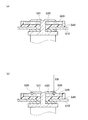
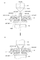
このような出力端子の構造として、例えば、図1(a)に示すようにして、電池ケースQ10内の発電要素と導通する内部導通部材Q20を、電池ケースQ10の外部に位置する外部端子部材Q30にかしめて固定したものも考えられる。具体的には、内部導通部材Q20は、外部端子部材Q30の貫通孔Q31を挿通して、電池ケースQ10内から外部に突出し、この突出した部位が外部端子部材Q30側に向けてプレスされ、貫通孔Q31よりも径大な形状に塑性変形されて、外部端子部材Q30を押圧するようにかしめてなる。 As a structure of such an output terminal, for example, as shown in FIG. 1A, an internal conductive member Q20 that is electrically connected to a power generation element in the battery case Q10 is connected to an external terminal member Q30 that is located outside the battery case Q10. It can also be fixed in place. Specifically, the internal conduction member Q20 is inserted through the through hole Q31 of the external terminal member Q30 and protrudes from the battery case Q10 to the outside, and the protruded portion is pressed toward the external terminal member Q30 and penetrates therethrough. The outer terminal member Q30 is crimped so as to be plastically deformed into a shape larger in diameter than the hole Q31.
このような端子構造において、外部端子部材Q30と内部導通部材Q20とを溶接して接合強度を高めたい場合に、例えば、図1(b)に示すように、図中上方から下方に向けて、エネルギービーム(例えば、電子ビーム)EBを照射させて貫通溶接を行うことが考えられる。
しかしながら、このエネルギービーム(電子ビーム)EBを、内部導通部材Q20を介して外部端子部材Q30にまで届かせてこれらを溶融させて、溶接部Q50を形成すると、内部導通部材Q20に多くの熱がかかる。このため、その熱の一部が、外部端子部材Q30を通じて、この外部端子部材Q30と電池ケースQ10との間を絶縁する絶縁樹脂からなる樹脂スペーサQ40にまで到達してしまい、この熱によってこの樹脂スペーサQ40を変質させてしまう虞がある。
また、貫通溶接では、内部導通部材Q20と外部端子部材Q30とが確実に溶接されているかどうかを、外観により確認し難い。
なお、エネルギービームとして、電子ビームの他、レーザ、イオンビーム等を用いても同様の不具合がある。
In such a terminal structure, when welding the external terminal member Q30 and the internal conduction member Q20 to increase the joint strength, for example, as shown in FIG. It is conceivable to perform through welding by irradiating an energy beam (for example, an electron beam) EB.
However, when this energy beam (electron beam) EB reaches the external terminal member Q30 via the internal conductive member Q20 and melts them to form the welded portion Q50, a large amount of heat is generated in the internal conductive member Q20. Take it. Therefore, part of the heat reaches the resin spacer Q40 made of an insulating resin that insulates between the external terminal member Q30 and the battery case Q10 through the external terminal member Q30. The spacer Q40 may be altered.
Moreover, in penetration welding, it is difficult to confirm by appearance whether or not the internal conduction member Q20 and the external terminal member Q30 are reliably welded.
It should be noted that there is a similar problem if an electron beam, a laser, an ion beam, or the like is used as the energy beam.
本発明は、かかる問題に鑑みてなされたものであって、樹脂スペーサの変質を抑制しつつ、内部導通部材と外部端子部材とを溶接可能な電池、このような電池を搭載した車両及び電池搭載機器を提供することを目的とする。また、このような電池の製造方法を提供することを目的とする。 The present invention has been made in view of such a problem, and a battery capable of welding an internal conductive member and an external terminal member while suppressing deterioration of a resin spacer, a vehicle equipped with such a battery, and a battery mounted The purpose is to provide equipment. Moreover, it aims at providing the manufacturing method of such a battery.
そして、その解決手段は、発電要素と、上記発電要素を収容してなる電池ケースと、上記電池ケース内に配置されて、上記発電要素の一方の電極に電気的に導通してなる内部導通部材であって、上記電池ケースを貫通して、この電池ケースの外部に突出する貫通接続部を有する内部導通部材と、上記電池ケースの外部に配置され、上記内部導通部材の上記貫通接続部と溶接された外部端子部材であって、溶接により上記内部導通部材の上記貫通接続部と共に溶け込んだ溶接部を為してなる外部端子部材と、上記電池ケースと上記外部端子部材のうち少なくとも上記溶接部よりも上記電池ケース側の部位との間に介在する樹脂スペーサと、を備える電池であって、上記貫通接続部は、上記外部端子部材の外表面のうち上記電池ケースに対向する面とは逆側に位置する外側面に重なる重畳部を含み、上記溶接部は、エネルギービームを用いた、上記重畳部と上記外部端子部材との突合せ溶接により、上記重畳部及び上記外部端子部材内に形成されてなる電池である。 And the solution means includes a power generation element, a battery case containing the power generation element, and an internal conduction member disposed in the battery case and electrically connected to one electrode of the power generation element An internal conductive member having a through-connection portion that penetrates the battery case and protrudes to the outside of the battery case, and is disposed outside the battery case and welded to the through-connection portion of the internal conductive member. An external terminal member comprising a welded portion melted together with the through-connecting portion of the internal conductive member by welding, and at least the welded portion of the battery case and the external terminal member And a resin spacer interposed between the battery case side portion and the through-connection portion facing the battery case on the outer surface of the external terminal member. And an overlapping portion that overlaps with the outer surface located on the opposite side, and the welding portion is formed in the overlapping portion and the external terminal member by butt welding of the overlapping portion and the external terminal member using an energy beam. It is a battery formed in.
本発明の電池では、外部端子部材の外側面に、内部導通部材のうち貫通接続部の重畳部を重ね、エネルギービームを用いた、重畳部と外部端子部材とを突合せ溶接により、溶接部を、重畳部及び外部端子部材内に形成している。このため、例えば、重畳部を貫通して行う貫通溶接に比して、溶接に要するエネルギーを少なくすることができるので、溶接の熱による樹脂スペーサの変質を抑制することができる。
また、重畳部と外部端子部材との溶接が確実に行われていることを、外観により、容易に判別することができる。
In the battery of the present invention, on the outer surface of the external terminal member, the overlapping portion of the through connection portion of the internal conduction member is overlapped, and the overlapping portion and the external terminal member using the energy beam are butt welded, Formed in the overlapping portion and the external terminal member. For this reason, since the energy required for welding can be reduced as compared with, for example, through welding performed by penetrating the overlapping portion, it is possible to suppress deterioration of the resin spacer due to heat of welding.
Further, it is possible to easily determine from the appearance that the overlapping portion and the external terminal member are reliably welded.
なお、内部導通部材は、発電要素の一方の電極の電極板と導通しているが、直接接続していても、間接的に接続していても良い。また、外部端子部材及び内部導通部材と、電池ケースとは、絶縁されていても、導通していても良い。従って、樹脂スペーサは、外部端子部材と電池ケースとを絶縁していても、絶縁していなくても良い。 In addition, although the internal conduction member is electrically connected to the electrode plate of one electrode of the power generation element, the internal conduction member may be directly connected or indirectly connected. In addition, the external terminal member and the internal conductive member and the battery case may be insulated or conductive. Therefore, the resin spacer may or may not insulate the external terminal member and the battery case.
また、内部導通部材の貫通接続部は、重畳部で外部端子部材と溶接していれば良い。さらに、エネルギービームには、例えば、レーザ、電子ビーム、イオンビーム等が挙げられる。 Moreover, the penetration connection part of an internal conduction member should just be welded with the external terminal member in the superimposition part. Furthermore, examples of the energy beam include a laser, an electron beam, and an ion beam.
さらに、上述の電池であって、前記外部端子部材は、前記外側面の側に、周囲の低位部よりも外方に膨出して高位となる膨出部を有し、前記内部導通部材の前記貫通接続部の前記重畳部は、上記外部端子部材のうち、上記低位部に重なると共に、自身の端部が、上記膨出部の側面に突き合わせられ、上記膨出部と溶接されてなる電池とすると良い。 Furthermore, in the battery described above, the external terminal member has, on the outer surface side, a bulging portion that bulges outward from a surrounding low level portion and becomes a high level, and the internal conduction member has the bulging portion. The overlapping portion of the through-connecting portion overlaps the low-order portion of the external terminal member, and has its own end faced against the side surface of the bulging portion and welded to the bulging portion. Good.
本発明の電池では、重畳部が外部端子部材の低位部に重なる一方、重畳部の端部が膨出部の側面と突き合わせられて溶接されてなるので、確実に突合せ溶接を行った電池とすることができる。
また、外部端子部材のうちでも膨出部と溶接するので、この膨出部を設けずに溶接した場合に比して、溶接部から樹脂スペーサまでの間に介在する、外部端子部材の寸法を確保できる。このため、樹脂スペーサへの熱の伝わりを抑制することができ、熱による樹脂スペーサの変質をさらに抑制することができる。
In the battery of the present invention, the overlapping portion overlaps the lower portion of the external terminal member, while the end portion of the overlapping portion is abutted against the side surface of the bulging portion and welded. be able to.
Also, since the outer terminal member is welded to the bulging portion, the dimension of the external terminal member interposed between the welded portion and the resin spacer is smaller than when welding without providing the bulging portion. It can be secured. For this reason, transmission of heat to the resin spacer can be suppressed, and alteration of the resin spacer due to heat can be further suppressed.
なお、膨出部の側面としては、例えば、膨出部が柱状の場合の側面(筒面)、膨出部が錐又は錐台状である場合の側面(斜面)が挙げられる。 Examples of the side surface of the bulging portion include a side surface (tubular surface) when the bulging portion is columnar, and a side surface (slope) when the bulging portion is conical or frustum-shaped.
さらに、上述のいずれかの電池であって、前記重畳部は、前記電池ケースに前記貫通接続部を貫通させた後の、上記貫通接続部の一部をかしめ変形させて形成してなる電池とすると良い。 Furthermore, the battery according to any one of the above, wherein the overlapping portion is formed by caulking and deforming a part of the through-connection portion after the through-connection portion is passed through the battery case. Good.
本発明の電池では、電池ケースに貫通接続部を貫通させた後に、貫通接続の一部をかしめ変形させて重畳部を形成してなる。このため、電池ケースに貫通接続部を貫通させる際の、貫通接続部の形状によらず、適切な形状の重畳部を容易に形成した電池とすることができる。 In the battery according to the present invention, after the through-connection portion is passed through the battery case, a part of the through-connection is caulked and deformed to form the overlapping portion. For this reason, it can be set as the battery which formed the superimposition part of an appropriate shape easily irrespective of the shape of the penetration connection part at the time of making a penetration connection part penetrate the battery case.
さらに、他の解決手段は、発電要素と、上記発電要素を収容してなる電池ケースと、上記電池ケース内に配置されて、上記発電要素の一方の電極に電気的に導通してなる内部導通部材であって、上記電池ケースを貫通して、この電池ケースの外部に突出する貫通接続部を有する内部導通部材と、上記電池ケースの外部に配置され、上記内部導通部材の上記貫通接続部と溶接された外部端子部材であって、溶接により上記内部導通部材の上記貫通接続部と共に溶け込んだ溶接部を為してなる外部端子部材と、上記電池ケースと上記外部端子部材のうち少なくとも上記溶接部よりも上記電池ケース側の部位との間に介在する樹脂スペーサと、を備える電池であって、上記外部端子部材は、その外表面のうち上記電池ケースに対向する面とは逆側に位置する外側面の側に、周囲の低位部よりも外方に膨出して高位となる膨出部を有し、上記貫通接続部は、上記外部端子部材を貫通する端子貫通部と、上記端子貫通部よりも、拡径された形態を有し、上記外部端子部材のうち上記低位部の上記外側面に重なると共に、自身の端部が、上記膨出部の側面に突き合わせられた重畳部と、を含み、上記溶接部は、エネルギービームを用いた、上記重畳部の端部と上記外部端子部材の上記膨出部との突合せ溶接により、上記重畳部及び上記外部端子部材内に形成されてなり、上記樹脂スペーサは、絶縁性樹脂からなり、上記電池ケースと上記外部端子部材との間を絶縁してなる電池である。 Further, another solution includes: a power generation element; a battery case containing the power generation element; and an internal continuity disposed in the battery case and electrically connected to one electrode of the power generation element. An internal conductive member having a through-connection portion that penetrates the battery case and protrudes to the outside of the battery case; and the through-connection portion of the internal conductive member that is disposed outside the battery case. An external terminal member welded to form a welded portion melted together with the through-connecting portion of the internal conductive member by welding, and at least the welded portion of the battery case and the external terminal member And a resin spacer interposed between the battery case side portion and the external terminal member on the opposite side to the surface facing the battery case of the outer surface. A bulging portion that bulges outward from the surrounding lower level portion and becomes higher than the surrounding lower level portion, and the through connection portion includes a terminal through portion that penetrates the external terminal member, and the terminal A superposed portion having a form expanded in diameter than the penetrating portion, overlapping with the outer side surface of the lower portion of the external terminal member, and having an end portion thereof butted against the side surface of the bulging portion, The welded portion is formed in the overlapped portion and the external terminal member by butt welding the end portion of the overlapped portion and the bulging portion of the external terminal member using an energy beam. Thus, the resin spacer is a battery made of an insulating resin and insulated between the battery case and the external terminal member.
本発明の電池では、内部導通部材における貫通接続部の重畳部が外部端子部材の低位部に重なると共に、膨出部の側面と重畳部の端部とが突き合わせられ、溶接されてなるので、確実に突合せ溶接を行った電池とすることができる。
また、重畳部と外部端子部材との溶接が確実に行われていることを、外観上から、容易に判別することができる。
さらに、溶接部から、絶縁性樹脂からなる樹脂スペーサまでの間に介在する、外部端子部材の寸法を確保できるので、樹脂スペーサへの熱の伝わりを抑制することができ、熱による樹脂スペーサの変質を抑制でき、電池ケースと外部端子部材との間を確実に絶縁することができる。
In the battery of the present invention, the overlapping portion of the through-connection portion in the internal conduction member overlaps the lower portion of the external terminal member, and the side surface of the bulging portion and the end portion of the overlapping portion are abutted and welded. The battery can be a butt welded battery.
Further, it can be easily determined from the appearance that the overlapping portion and the external terminal member are reliably welded.
Furthermore, since the dimension of the external terminal member interposed between the welded portion and the resin spacer made of an insulating resin can be secured, the transfer of heat to the resin spacer can be suppressed, and the resin spacer is altered by heat. And the battery case and the external terminal member can be reliably insulated.
さらに、他の解決手段は、上述のいずれかの電池を搭載した車両である。 Another solution is a vehicle equipped with any of the above-described batteries.
本発明の車両では、上述の電池を搭載しているので、樹脂スペーサの変質を抑制しつつ電池の外部端子部材と内部導通部材との接合強度を確保した車両とすることができる。 In the vehicle of the present invention, since the above-described battery is mounted, it is possible to provide a vehicle that secures the bonding strength between the external terminal member of the battery and the internal conductive member while suppressing the deterioration of the resin spacer.
なお、車両としては、その動力源の全部あるいは一部に電池による電気エネルギを使用している車両であれば良く、例えば、ハイブリッド自動車、プラグインハイブリッド自動車、電気自動車、プラグイン電気自動車、ハイブリッド鉄道車両、フォークリフト、電気車いす、電動アシスト自転車、電動スクータが挙げられる。 The vehicle may be a vehicle that uses electric energy from a battery for all or a part of its power source. For example, a hybrid vehicle, a plug-in hybrid vehicle, an electric vehicle, a plug-in electric vehicle, a hybrid railway Examples include vehicles, forklifts, electric wheelchairs, electric assist bicycles, and electric scooters.
さらに、他の解決手段は、前述のいずれかの電池を搭載した電池搭載機器である。 Furthermore, another solution is a battery-equipped device equipped with any of the batteries described above.
本発明の電池搭載機器は前述の電池を搭載しているので、樹脂スペーサの変質を抑制しつつ電池の外部端子部材と内部導通部材との接合強度を確保した電池搭載機器とすることができる。 Since the battery-equipped device of the present invention is equipped with the above-described battery, it can be a battery-equipped device in which the bonding strength between the external terminal member and the internal conductive member of the battery is secured while suppressing the deterioration of the resin spacer.
なお、電池搭載機器としては、電池を搭載しこれをエネルギー源の少なくとも1つとして利用する機器であれば良く、例えば、パーソナルコンピュータ、携帯電話、電池駆動の電動工具、無停電電源装置など、電池で駆動される各種の家電製品、オフィス機器、産業機器が挙げられる。 The battery-equipped device may be any device equipped with a battery and using it as at least one of the energy sources. For example, a battery such as a personal computer, a mobile phone, a battery-driven electric tool, an uninterruptible power supply, Various household appliances, office equipment, and industrial equipment driven by
さらに、他の解決手段は、発電要素と、上記発電要素を収容してなる電池ケースと、上記電池ケース内に配置されて、上記発電要素の一方の電極に電気的に導通してなる内部導通部材であって、上記電池ケースを貫通して、この電池ケースの外部に突出する貫通接続部を有する内部導通部材と、上記電池ケースの外部に配置され、上記内部導通部材の上記貫通接続部と溶接された外部端子部材であって、溶接により上記内部導通部材の上記貫通接続部と共に溶け込んだ溶接部を為してなる外部端子部材と、上記電池ケースと上記外部端子部材のうち少なくとも上記溶接部よりも上記電池ケース側の部位との間に介在する樹脂スペーサと、を備える電池の製造方法であって、上記貫通接続部は、上記外部端子部材の外表面のうち上記電池ケースに対向する面とは逆側に位置する外側面に重なる重畳部を含み、エネルギービームを、上記重畳部と上記外部端子部材との突合せ部分に照射して、上記重畳部及び上記外部端子部材内に上記溶接部を形成形態に、溶接する溶接工程、を備える電池の製造方法である。 Further, another solution includes: a power generation element; a battery case containing the power generation element; and an internal continuity disposed in the battery case and electrically connected to one electrode of the power generation element. An internal conductive member having a through-connection portion that penetrates the battery case and protrudes to the outside of the battery case; and the through-connection portion of the internal conductive member that is disposed outside the battery case. An external terminal member welded to form a welded portion melted together with the through-connecting portion of the internal conductive member by welding, and at least the welded portion of the battery case and the external terminal member A resin spacer interposed between the battery case and the battery case side, wherein the through-connecting portion is the battery case of the outer surface of the external terminal member. It includes an overlapping portion that overlaps the outer surface located on the opposite side of the facing surface, and irradiates the abutting portion between the overlapping portion and the external terminal member to radiate the energy beam into the overlapping portion and the external terminal member. It is a manufacturing method of a battery provided with the welding process which welds the said welding part to a formation form.
本発明の電池の製造方法では、上述の溶接工程を備えるので、例えば、重畳部を貫通して外部端子部材に溶接する貫通溶接に比して、溶接に要するエネルギーを少なくすることができ、溶接の熱による樹脂スペーサの変質を抑制した電池を製造できる。
また、重畳部と外部端子部材との溶接が確実に行われていることを、外観により、容易に判別することができる電池を製造できる。
Since the battery manufacturing method of the present invention includes the above-described welding process, the energy required for welding can be reduced as compared with, for example, through welding that penetrates the overlapping portion and is welded to the external terminal member. It is possible to manufacture a battery in which the resin spacer is prevented from being deteriorated due to the heat.
In addition, it is possible to manufacture a battery that can be easily discriminated from the appearance that the overlapping portion and the external terminal member are reliably welded.
さらに、上述の電池の製造方法であって、前記外部端子部材は、前記外側面の側に、周囲の低位部よりも外方に膨出して高位となる膨出部を有し、前記内部導通部材の前記貫通接続部の前記重畳部は、上記外部端子部材のうち、上記低位部に重なると共に、自身の端部が、上記膨出部の側面に突き合わせられてなり、前記溶接工程は、上記重畳部の上記端部と上記外部端子部材の上記膨出部とを溶接する電池の製造方法とすると良い。 Furthermore, in the battery manufacturing method described above, the external terminal member has, on the outer surface side, a bulging portion that bulges outward from a surrounding low-level portion and becomes a high level, and The overlapping portion of the through-connecting portion of the member overlaps the low-order portion of the external terminal member, and its end is abutted against the side surface of the bulging portion. It is preferable to use a battery manufacturing method in which the end portion of the overlapping portion and the bulging portion of the external terminal member are welded.
本発明の電池の製造方法では、重畳部を外部端子部材の低位部に重ねると共に、膨出部の側面と重畳部の端部とを突き合わせて、これらを溶接するので、確実に突合せ溶接を行った電池を製造できる。
また、外部端子部材のうちでも膨出部と溶接するので、この膨出部を設けずに溶接した場合に比して、溶接部から樹脂スペーサまでの間に介在する、外部端子部材の寸法を確保できる。このため、樹脂スペーサへの熱の伝わりを抑制することができ、熱による樹脂スペーサの変質をさらに抑制した電池を製造することができる。
In the battery manufacturing method of the present invention, the overlapping portion is overlapped with the lower portion of the external terminal member, the side surface of the bulging portion and the end portion of the overlapping portion are butted, and these are welded together. Batteries can be manufactured.
Also, since the outer terminal member is welded to the bulging portion, the dimension of the external terminal member interposed between the welded portion and the resin spacer is smaller than when welding without providing the bulging portion. It can be secured. For this reason, the transmission of heat to the resin spacer can be suppressed, and a battery in which alteration of the resin spacer due to heat is further suppressed can be manufactured.
さらに、上述のいずれかの電池の製造方法であって、前記溶接工程に先立ち、前記電池ケースに前記貫通接続部を貫通させた後に、上記貫通接続部の一部をかしめ変形して、前記重畳部を形成する重畳部かしめ形成工程、を備える電池の製造方法とすると良い。 Further, in any one of the above-described battery manufacturing methods, prior to the welding step, after the through-connection portion is penetrated through the battery case, a part of the through-connection portion is caulked and deformed, and the superposition is performed. It is good to set it as the manufacturing method of a battery provided with the superimposition part caulking formation process which forms a part.
本発明の電池の製造方法では、上述の重畳部かしめ形成工程を備えるので、電池ケースに貫通接続部を貫通させる際の、貫通接続部の形状によらず、容易に適切な形状の重畳部を形成した電池を製造することができる。 In the battery manufacturing method of the present invention, since the above-described overlapping portion caulking formation step is provided, an overlapping portion having an appropriate shape can be easily formed regardless of the shape of the through connection portion when the through connection portion is passed through the battery case. The formed battery can be manufactured.
(実施形態1)
次に、本発明の実施形態1について、図面を参照しつつ説明する。
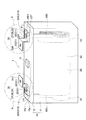
まず、本実施形態1にかかる電池1について説明する。図2に電池1を部分的に透視した斜視図を示す。この電池1は、破線で示す発電要素50、この発電要素50を収容する矩形箱形の電池ケース10の他に、正極端子20及び負極端子30を備える捲回形のリチウムイオン二次電池である。
(Embodiment 1)
Next, Embodiment 1 of the present invention will be described with reference to the drawings.
First, the battery 1 according to the first embodiment will be described. FIG. 2 is a perspective view of the battery 1 partially seen through. The battery 1 is a wound lithium ion secondary battery that includes a
このうち、発電要素50は、電池ケース10内で、帯状の正電極板51及び負電極板52が、ポリエチレンからなる帯状のセパレータ53を介して扁平形状に捲回されてなる(図2参照)。なお、この正電極板51には正極端子20が、負電極板52には負極端子30が、それぞれ溶接されており、電気的に接続してなる。
Among them, the
また、電池ケース10は、いずれもアルミニウムからなる電池ケース本体11及び封口蓋12を有する。このうち電池ケース本体11は有底矩形箱形であり、内側全面に樹脂からなる絶縁フィルム(図示しない)を貼付している。なお、電池ケース10内には、エチレンカーボネート(EC)とエチルメチルカーボネート(EMC)との混合有機溶媒に溶質(LiPF6)を添加してなる有機電解液の電解液(図示しない)が液密に保持されている。
The
このうち、封口蓋12は矩形板状であり、電池ケース本体11の開口部11Aを閉塞して、この電池ケース本体11に溶接されている。この封口蓋12の、図2中、上方を向く上面12aには、正極端子20の正極外部端子部材21、及び、負極端子30の負極外部端子部材31が、それぞれ配置されている。また、この封口蓋12は、後述の正極内部導通部材25,負極内部導通部材35をそれぞれ挿通可能なケース貫通孔12Kを有する(図4,6参照)。さらに、この封口蓋12には、矩形板状の安全弁71が装着されている。
Among these, the sealing
正極端子20は、電池ケース10の外部に配置された正極外部端子部材21と、主として電池ケース10内に配置された正極内部導通部材25により構成されている(図2,3,4参照)。なお、正極内部導通部材25は、後述するように、図7に示すかしめ変形前の未変形正極内部導通部材125のうち、未変形正極貫通接続部126を正極外部端子部材21に貫通させて突出させた後に、未変形正極貫通接続部126の先端側を、軸線XAの径方向外側DRに十字状に押し拡げてかしめ変形させたものである。
The
アルミニウムからなる正極内部導通部材25は、電池ケース10の内側に位置する正極内部端子本体部29と、これから延びて、電池ケース10を貫通して、この電池ケース10の外部に突出し、上述の正極外部端子部材21と接続してなる正極貫通接続部26とを有する(図4参照)。
このうち、正極内部端子本体部29は、封口蓋12のケース貫通孔12Kよりも径大の矩形板状の正極ケース結合部29F、及び、この正極ケース結合部29Fから発電要素50の正電極板51に向けて屈曲し、この正電極板51と溶接してなる正極集電部29Gを含む(図4参照)。このため、正極内部導通部材25は、発電要素50の正電極板51に電気的に導通してなる。
The positive electrode
Among these, the positive electrode internal terminal
また、正極貫通接続部26は、正極外部端子部材21の正極端子貫通孔22Kを貫通してなる円柱棒状の正極端子貫通部28と、これに連なって電池ケース10(封口蓋12)の外部に露出し、かしめ変形させられて正極外部端子部材21の正極固定部22を軸線XA方向内側(図3,4中、下方)に向けて押圧してなる正極重畳部27とを有する(図3,4参照)。
Moreover, the positive electrode
一方、アルミニウムからなる正極外部端子部材21は、図2に示すようにクランク状に屈曲しており、封口蓋12に固定されている正極固定部22と、これと平行に延びる正極締結部23とを有する。このうち、正極締結部23は、例えば、複数の電池1がバスバ(図示しない)を通じて接続される際に、ボルトを挿通させる締結用貫通孔23Hを有する。
また、正極固定部22は、正極外部端子部材21の外表面21Sのうち、封口蓋12の上面12aに対向している正極固定部第2面22B、及び、この正極固定部第2面22Bの逆側に位置する、即ち、図2中、上方を向く正極固定部第1面22Aを有する。さらに、この正極固定部22の中央付近には、正極固定部第1面22Aと正極固定部第2面22Bとの間を貫通する正極端子貫通孔22Kが穿孔されている(図4参照)。
On the other hand, the positive electrode
The positive
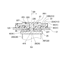
この正極固定部22は、正極固定部第1面22A側に、平面状の第1平面部22Xを有するほか、この第1平面部22Xから、図2中、上方に向けて膨出して第1平面部22Xよりも高位となる円錐台形状の正極膨出部22Tを複数(本実施形態1では4箇所)有する(図3参照)。この正極膨出部22Tは、側面(斜面,錐面)22TFを含んでいる。
The positive
具体的には、これら4つの正極膨出部22T,22T,22T,22Tは、いずれも正極固定部22の正極端子貫通孔22K(軸線XA)から等距離で、かつ、四方に均等に配置されている。一方、正極重畳部27は、かしめ変形により、正極膨出部22T同士の間に延びるように、十字状に4つの腕部27Hを拡げて形成されている。かくして、十字状の正極重畳部27周縁の端部のうち、腕部27H同士の間の間端部27Rが、正極膨出部22Tの側面22TFと突き合わせられている。
なお、正極重畳部27が、後述する負極重畳部37と異なり、十字状にしてあるので、図2中、上方から、電池ケース10を目視すれば(図3(b)参照)、その正極重畳部27で接合された正極端子10が正極(+極)側であることを容易に認識することができる。
Specifically, the four positive
In addition, since the positive
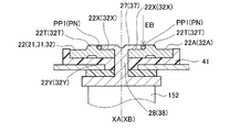
また、正極固定部22の正極膨出部22Tは、上述した正極貫通接続部26の正極重畳部27と溶接されてなる。具体的には、後述のレーザビームEBを用いた溶接により、この正極膨出部22Tと正極重畳部27との間に、これらが溶け込んだ正極溶接部PP1が形成されている。この正極溶接部PP1は、正極膨出部22Tと間端部27Rとの界面の全てを溶融してなり、図3(a)中、上方から見て正極重畳部27の側面の円周に沿った円弧形状をなす(図3(a),(b)参照)。
The positive
なお、この正極溶接部PP1は、正極固定部22の正極固定部第1面22A側に位置しており、この正極溶接部PP1よりも電池ケース10(封口蓋12)側、即ち、正極固定部22の正極固定部第2面22B側には、次述する絶縁部材41に当接する平面状の第2平面部22Yが位置している(図4参照)。
また、かしめ変形により形成してなる正極重畳部27は、正極固定部22の第1平面部22Xに重なりつつ、自身の間端部27Rと正極膨出部22Tの側面22TFとが突合せ溶接されてなる。このため、正極外部端子部材21と正極重畳部27との接合強度を、これらをかしめのみで接合してなる場合より増大させることができる。
The positive electrode welded part PP1 is located on the positive electrode fixing part
In addition, the positive
また、封口蓋12と正極外部端子部材21の正極固定部22との間には、絶縁部材41が介在している(図2,3,4参照)。この絶縁部材41は、絶縁性樹脂(本実施形態1では、ナイロン)からなり、矩形板状の本体部42と、この本体部42から、図4中、下方に突出するリング状の突出部43と、本体部の周縁から、図4中、上方に突出する枠状の枠部44とを有する(図4,図7参照)。また、この本体部42及び突出部43には、これを貫通する絶縁貫通孔41Kが穿孔されている。なお、突出部43は、封口蓋12の各々のケース貫通孔12Kに遊挿されて、絶縁部材41の位置決めを行う。
また、封口蓋12と正極内部導通部材25の正極内部端子本体部29との間には、ガスケット45が配置されている。このガスケット45は、ガスケット貫通孔45Kを有する環状で絶縁性の合成ゴム(本実施形態1では、エチレン−プロピレン−ジエンゴム)からなる。このガスケット45は、封口蓋12と正極内部導通部材25の正極内部端子本体部29との間に挟持されて、両者間をシールしている。
Further, an insulating
Further, a
本実施形態1にかかる電池1では、正極重畳部27と正極外部端子部材21とを突合せ溶接しているので、正極重畳部27を貫通し、これと正極外部端子部材21の第1平面部22Xとを貫通溶接した場合に比して、溶接に要するエネルギを少なくできる。従って、溶接の熱による絶縁部材41の変質を抑制することができる。
また、正極重畳部27と正極外部端子部材21との溶接が確実に行われていることを、その外観から、容易に判別することができる。
In the battery 1 according to the first embodiment, since the positive
In addition, it can be easily determined from the appearance that the positive
また、正極重畳部27が正極外部端子部材21(正極固定部22)の第1平面部22Xに重なる一方、その間端部27Rが、第1平面部22Xよりも突出した正極膨出部22Tの側面22TFと突合せ溶接されているので、正極外部端子部材21と正極内部導通部材25とを確実に溶接した電池1となっている。
また、正極外部端子部材21のうちでも、第1平面部22Xよりも突出した正極膨出部22Tと溶接しているので、この正極膨出部22Tを設けずに溶接した場合に比して、正極溶接部PP1から絶縁部材41までの間に介在する、正極外部端子部材21(正極固定部22の第2平面部22Y)の寸法(厚み寸法)を大きくできる。このため、絶縁部材41への熱の伝わりを抑制することができ、熱による絶縁部材41の変質をさらに抑制することができる。
Further, the positive
Also, among the positive electrode external
また、正極貫通接続部26は、正極固定部22の正極固定部第1面22Aに重なる、正極重畳部27を含む。この正極重畳部27は、電池ケース10に正極貫通接続部26を貫通させた後に、電池ケース10の外側に突出したその先端側をかしめ変形して形成してなる。これにより、電池ケース10及び正極外部接続端子21は固定されている(図2,3,4参照)。このため、電池ケース10に正極貫通接続部26を貫通させる際の、正極貫通接続部26の形状によらず、適切な形状の正極重畳部27を容易に形成した電池1とすることができる。
Further, the positive electrode through
一方、負極端子30も、正極端子20と同様に、電池ケース10の外部に位置する負極外部端子部材31と、主として電池ケース10の内部に位置する負極内部導通部材35により構成されている(図2,5,6参照)。なお、負極内部導通部材35は、図11に示すかしめ変形前の未変形負極内部導通部材135のうち、未変形負極貫通接続部136を負極外部端子部材31に貫通させて突出させた後に、未変形負極貫通接続部136を、軸線XBの径方向外側DRに略楕円形状に押し拡げてかしめ変形させたものである。
On the other hand, the
銅からなる負極内部導通部材35は、正極側と同様、電池ケース10の内側に位置する負極内部端子本体部39と、電池ケース10を貫通して、この電池ケース10の外部に突出し、負極外部端子部材31と接続してなる負極貫通接続部36とを有する(図6参照)。
このうち、負極内部端子本体部39は、正極側と同様、矩形板状の負極ケース結合部39F、及び、発電要素50の負電極板52と溶接してなる負極集電部39Gを含む(図6参照)。このため、負極内部導通部材35は、発電要素50の負電極板52に電気的に導通してなる。
Similarly to the positive electrode side, the negative electrode internal conducting
Among these, the negative electrode internal terminal
また、負極貫通接続部36は、負極外部端子部材31の負極端子貫通孔32Kを貫通してなる円柱棒状の負極端子貫通部38と、これに連なって電池ケース10(封口蓋12)の外部に露出し、かしめ変形させられて負極外部端子部材31の負極固定部32を軸線XB方向内側(図5,6中、下方)に向けて押圧してなる負極重畳部37とを有する(図5,6参照)。
Further, the negative electrode
一方、銅からなる負極外部端子部材31は、正極側と同様、封口蓋12に固定されている負極固定部32と、正極側と同様、締結用貫通孔33Hを含む負極締結部33とを有する(図2参照)。
このうち負極固定部32は、負極外部端子部材31の外表面31Sのうち、封口蓋12の上面12aに対向している負極固定部第2面32B、及び、この負極固定部第2面32Bの逆側に位置する負極固定部第1面32Aを有する。さらに、この負極固定部32の中央付近には、正極側と同様、負極端子貫通孔32Kが穿孔されている(図6参照)。
On the other hand, the negative electrode
Among these, the negative
この負極固定部32は、負極固定部第1面32A側に、平面状の第1平面部32Xを有するほか、この第1平面部32Xから、図2中、上方に向けて膨出して第1平面部32Xよりも高位となる負極膨出部32Tを複数(本実施形態1では2箇所)有する(図5参照)。
このうち、第1平面部32Xの負極膨出部32Tは、図5(a),(b)に示すように、軸線XBを囲むように湾曲したU字形状(半円環状)をなし、自身の縦断面は台形形状をなした錐台形状である(図8(a)参照)。負極膨出部32Tは、先細の側面(斜面)32TFを含んでいる。
The negative
Among these, as shown in FIGS. 5A and 5B, the negative
具体的には、これら2つの負極膨出部32T,32Tは、いずれも各部が負極固定部32の負極端子貫通孔32K(軸線XA)から等距離になるよう湾曲して配置されている。一方、負極重畳部37は、かしめ変形により、負極膨出部32T同士の間に延びるように、長径側に2つの腕部37Hを拡げて形成された略楕円形状である。従って、負極重畳部37周縁の端部のうち、短径側に位置する短径端部37Rが、負極膨出部32Tの側面32TFと突き合わせられている。
Specifically, the two negative
また、この負極固定部32の負極膨出部32Tは、上述した負極重畳部37の短径端部37Rと溶接されてなる。具体的には、後述のレーザビームEBを用いた溶接により、この負極膨出部32Tと短径端部37Rとの間に、これらが溶け込んだ負極溶接部PNが形成されている。この負極溶接部PNは、負極膨出部32Tと短径端部37Rとの界面の全てを溶融してなり、図5(a)中、上方から見て負極重畳部37の湾曲に沿った円弧形状をなす(図5(a),(b)参照)。
The negative
なお、この負極溶接部PNは、負極固定部32の負極固定部第1面22A側に位置しており、この負極溶接部PNよりも電池ケース10(封口蓋12)側、即ち、負極固定部32の負極固定部第2面32B側には、絶縁部材41と当接する平面状の第2平面部32Yが位置している(図6参照)。
また、かしめ変形により形成した負極重畳部37は、負極固定部32の第1平面部32Xに重なりつつ、自身の短径端部37Rと負極膨出部32Tの側面32TFとが突合せ溶接されてなる。このため、負極外部端子部材31と負極重畳部27との接合強度を、これらをかしめのみで接合してなる場合より増大させることができる。
The negative electrode welded portion PN is positioned on the negative electrode fixing portion
The negative
また、封口蓋12と負極外部端子部材31の負極固定部32との間にも、正極側と同様、本体部42と突出部43と枠部44とを有する絶縁部材41が介在している(図2,5,6参照)。
また、封口蓋12と負極内部導通部材35の負極内部端子本体部39との間にも、正極側と同様に、ガスケット45が挟持されて、両者間をシールしている。
In addition, an insulating
In addition, a
かくして、本実施形態1にかかる電池1では、負極重畳部37と負極外部端子部材31とを突合せ溶接しているので、負極重畳部37を貫通し、これと負極外部端子部材31の第1平面部32Xとを貫通溶接した場合に比して、溶接に要するエネルギーを少なくできる。従って、上述の正極端子20側と同様、負極端子30側においても、溶接の熱による絶縁部材41の変質を抑制することができる。
また、負極重畳部37と負極外部端子部材31との溶接が確実に行われていることを、その外観から容易に判別することができる。
Thus, in the battery 1 according to the first embodiment, since the negative
Further, it can be easily determined from the appearance that the negative
また、負極重畳部37が負極外部端子部材31(負極固定部32)の第1平面部32Xに重なる一方、その短径端部37Rが、第1平面部32Xよりも突出した負極膨出部32Tの側面32TFと突合せ溶接されてなる。このため、負極端子30側においても、負極外部端子部材31と負極内部導通部材35とを確実に溶接した電池1となっている。
また、負極外部端子部材31のうちでも、第1平面部32Xよりも突出した負極膨出部32Tと溶接しているので、この負極膨出部32Tを設けずに溶接した場合に比して、負極溶接部PNから絶縁部材41までの間に介在する、負極外部端子部材31(負極固定部32の第2平面部32Y)の寸法(厚み寸法)を大きくできる。このため、絶縁部材41への熱の伝わりを抑制することができ、熱による絶縁部材41の変質をさらに抑制することができる。
The negative
Further, among the negative electrode external
また、負極貫通接続部36は、負極固定部32の負極固定部第1面32Aに重なる、負極重畳部37を含む。この負極重畳部37は、電池ケース10に負極貫通接続部36を貫通させた後に、電池ケース10の外側に突出したその先端側をかしめ変形して形成してなる。これにより、電池ケース10及び負極外部端子部材31は固定されている(図2,5参照)。このため、電池ケース10に負極貫通接続部36を貫通させる際の、負極貫通接続部36の形状によらず、適切な形状の負極重畳部37を容易に形成した電池1とすることができる。
The negative electrode through
次いで、本実施形態1にかかる電池1の製造方法について、図7〜11を参照しつつ説明する。
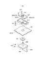
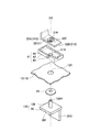
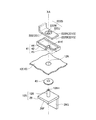
図7に、この電池1の正極端子20を構成する、かしめ変形前の未変形正極内部導通部材125、ガスケット45、封口蓋12、絶縁部材41、及び、正極外部端子部材21の分解斜視図を示す。
このうち、未変形正極内部導通部材125は、前述の正極内部端子本体部29と、このうちの正極内部端子本体部29から軸線XA方向に延びる円筒形状の未変形正極貫通接続部126とを有する。このうち、正極内部端子本体部29の正極集電部29Gは、図7に図示しないが、発電要素50の正電極板51と溶接されている。また、未変形正極貫通接続部126は、図7中、上方に開口する変形用穴126Hが凹設されている。
Next, a method for manufacturing the battery 1 according to the first embodiment will be described with reference to FIGS.
FIG. 7 is an exploded perspective view of the undeformed positive inner
Among these, the undeformed positive internal
まず、図7に示すように、未変形正極貫通接続部126を、ガスケット45のガスケット貫通孔45K、封口蓋12のケース貫通孔12K、絶縁部材41の絶縁貫通孔41K、及び、正極外部端子部材21の正極端子貫通孔22Kに、この順に挿通して、その先端側を正極外部端子部材21よりも突出させる。挿通後の未変形正極貫通接続部126とその周囲部分の断面図を図8(a)に示す。
First, as shown in FIG. 7, the undeformed positive through-
次に、電池1の製造方法のうち、正極端子20側における、重畳部かしめ形成工程について、図8,9を参照しつつ説明する。
図8(a)に示すように、略円錐形状の先端部151Aを有する拡径金型151を、未変形正極貫通接続部126の変形用穴126Hに向けて、軸線XAに沿って移動させる。またこれと同時に、平面152Bを有する平面金型152を、正極ケース結合部29Fの下方に当接させて、軸線XAに沿って正極外部端子部材21に向けて移動させる。
これにより、正極外部端子部材21の正極固定部第1面22Aよりも外側では、未変形正極貫通接続部126がカサ状(円錐筒状)に開いた形状とされる(図8(b)参照)。
Next, in the manufacturing method of the battery 1, the overlapping portion caulking process on the
As shown in FIG. 8A, the diameter-enlargement die 151 having a substantially
Thereby, outside the positive electrode fixing | fixed
さらに、図7に示すように、未変形正極貫通接続部126のうち、正極固定部第1面22Aの第1平面部22Xより外側(図9中、上方)に位置する部位を、押圧金型153を用いて変形させる。具体的には、押圧金型153を軸線XAに沿って回転させながら、その正極固定部第1面22Aより外側に位置する部位を軸線XAの径方向外側DRに拡径させつつ、第1平面部22Xに向けて押し倒す。これにより、第1平面部22Xを押圧してなる正極重畳部27ができあがる。
このとき、正極固定部第1面22Aに配置された正極膨出部22Tの側面22TFの一部に、正極重畳部27の間端部27Rが当接している(図9参照)。即ち、正極膨出部22Tの側面22TF及び正極重畳部27の間端部27Rが、突き合わせた状態で当接し合っており、この部分を突合せ部分JP1とする。
なお、正極重畳部27の腕部27Hが、隣り合う正極膨出部22T,22Tの間、即ち、間端部27R,27Rの間から軸線XAの径方向外側DRに向けていずれも延びて、正極重畳部27自身が十字状をなす(図3(b)参照)。
Further, as shown in FIG. 7, a portion of the undeformed positive through-
At this time, the
The
次に、電池1の製造方法のうち、正極端子20側における溶接工程では、図10に示すように、上述の突合せ部分JP1において、図10中、上方から下方に向けてレーザビームEBを照射して突合せ溶接を行う。これにより、正極重畳部27の間端部27Rと正極膨出部22Tの側面22TFとが溶融しあって正極溶接部PP1が形成される。
Next, in the battery 1 manufacturing method, in the welding process on the
本実施形態1にかかる電池1の製造方法では、上述の溶接工程を備えるので、例えば、正極重畳部27を貫通して正極外部端子部材21に貫通溶接する場合に比して、溶接に要するエネルギーを少なくすることができ、溶接の熱による絶縁部材41の変質を抑制した電池1を製造できる。
また、正極重畳部27を正極外部端子部材21の第1平面部22Xに重ねると共に、正極膨出部22Tの側面22TFと正極重畳部27の間端部27Rとを突き合わせて、これらがなす突合せ部分JP1を溶接するので、確実に突合せ溶接を行った電池1を製造できる。
また、正極外部端子部材21のうちでも正極膨出部22Tと溶接するので、この正極膨出部22Tを設けずに溶接した場合に比して、正極溶接部PP1から絶縁部材41までの間に介在する、正極外部端子部材21(正極固定部22の第2平面部22Y)の寸法(厚み寸法)を大きくできる。このため、絶縁部材41への熱の伝わりを抑制することができ、熱による絶縁部材41の変質をさらに抑制した電池1を製造することができる。
Since the manufacturing method of the battery 1 according to the first embodiment includes the above-described welding process, for example, the energy required for welding as compared to the case of penetrating and welding to the positive electrode
Further, the positive
In addition, since the positive electrode
また、本実施形態1にかかる電池1の製造方法では、溶接工程に先立ち、上述の重畳部かしめ形成工程を備えるので、電池ケース10に正極内部導通部材25の正極貫通接続部26を貫通させる際の、この正極貫通接続部26の形状によらず、適切な形状(本実施形態1では十字状)の正極重畳部27Tを容易に形成した電池1を製造することができる。
Moreover, since the manufacturing method of the battery 1 according to the first embodiment includes the above-described overlapping portion caulking formation step prior to the welding step, when the positive electrode through
次いで、図11に、この電池1の負極端子30を構成する、かしめ変形前の未変形負極内部導通部材135、ガスケット45、封口蓋12、絶縁部材41、及び、負極外部端子部材31の分解斜視図を示す。
このうち、未変形負極内部導通部材135は、前述の負極内部端子本体部39と、円筒形状の未変形負極貫通接続部136とを有する。このうち、負極内部端子本体部39の負極集電部39Gは、図11に図示しないが、発電要素50の負電極板52と既に溶接されている。また、未変形負極貫通接続部136は、図11中、上方に開口する変形用穴136Hが設けられている。
Next, FIG. 11 is an exploded perspective view of the undeformed negative electrode internal
Among these, the undeformed negative electrode
まず、図11に示すように、未変形負極貫通接続部136を、ガスケット45のガスケット貫通孔45K、封口蓋12のケース貫通孔12K、絶縁部材41の絶縁貫通孔41K、及び、負極外部端子部材31の負極端子貫通孔32Kに、この順に挿通して、その先端側を負極外部端子部材31よりも突出させる。
First, as shown in FIG. 11, the undeformed negative electrode through-connecting
次に、電池1の製造方法のうち、負極端子30側における、重畳部かしめ形成工程について、図8,9を参照しつつ説明する。
図8(a)に示すように、正極側と同様に、上述の拡径金型151を、未変形負極貫通接続部136の変形用穴136Hに向けて、軸線XBに沿って移動させる。またこれと同時に、上述の平面金型152を、負極ケース結合部39Fの下方に当接させて、軸線XBに沿って負極外部端子部材31に向けて移動させる。
これにより、負極外部端子部材31の負極固定部第1面32Aよりも外側では、未変形負極貫通接続部136がカサ状(円錐筒状)に開いた形状とされる(図8(b)参照)。
Next, in the manufacturing method of the battery 1, an overlapping portion caulking formation process on the
As shown in FIG. 8A, similarly to the positive electrode side, the above-described
As a result, on the outer side of the negative electrode fixing portion
さらに、図9に示すように、未変形負極貫通接続部136のうち、負極固定部第1面32Aの第1平面部32Xより外側(図9中、上方)に位置する部位を、押圧金型153を用いて変形させる。具体的には、押圧金型153を軸線XBに沿って回転させながら、その負極固定部第1面32Aより外側に位置する部位を軸線XBの径方向外側DRに拡径させつつ、第1平面部32Xに向けて押し倒す。これにより、第1平面部32Xを押圧してなる負極重畳部37ができあがる。
このとき、負極固定部第1面32Aに配置された負極膨出部32Tの側面32TFの一部に、負極重畳部37の短径端部37Rが当接している(図9参照)。即ち、負極膨出部32Tの側面32TF及び負極重畳部37の短径端部37Rが、突き合わせた状態で当接し合っており、この部分を突合せ部分JP2とする。
なお、負極重畳部37の腕部37Hが、短径端部27R,27Rの間から軸線XAの径方向外側DRに向けていずれも一直線上に延びて、負極重畳部37自身が略楕円形状をなす(図5(b)参照)。
Further, as shown in FIG. 9, a portion of the undeformed negative electrode
At this time, the short-
The
次に、電池1の製造方法のうち、負極端子30側における溶接工程では、図10に示すように、上述の突合せ部分JP2において、図10中、上方から下方に向けてレーザビームEBを照射して突合せ溶接を行う。これにより、負極重畳部37の短径端部37Rと負極膨出部32Tの側面32TFとが溶融しあって負極溶接部PNが形成される。
Next, in the manufacturing process of the battery 1, in the welding process on the
本実施形態1にかかる電池1の製造方法では、上述の溶接工程を備えるので、正極側と同様、溶接の熱による絶縁部材41の変質を抑制した電池1を製造できる。
また、負極重畳部37を負極外部端子部材31の第1平面部32Xに重ねると共に、負極膨出部32Tの側面32TFと負極重畳部37の短径端部37Rとを突き合わせて、これらがなす突合せ部分JP2を溶接するので、確実に突合せ溶接を行った電池1を製造できる。
また、正極側と同様に、負極外部端子部材21(負極固定部32の第2平面部32Y)の寸法(厚み寸法)を大きくできるので、絶縁部材41への熱の伝わりを抑制することができ、熱による絶縁部材41の変質をさらに抑制した電池1を製造することができる。
In the manufacturing method of the battery 1 according to the first embodiment, since the above-described welding process is provided, the battery 1 in which the deterioration of the insulating
In addition, the negative
Moreover, since the dimension (thickness dimension) of the negative electrode external terminal member 21 (the second
また、正極側と同様、電池ケース10に負極内部導通部材35の負極貫通接続部36を貫通させる際の、この負極貫通接続部36の形状によらず、適切な形状の負極重畳部37Tを容易に形成した電池1を製造することができる。
Similarly to the positive electrode side, the negative electrode overlapping portion 37T having an appropriate shape can be easily formed regardless of the shape of the negative electrode
上述の正極端子20側及び負極端子30側の溶接工程の後、内部導通部材25,35(正極集電部29G,負極集電部39G)を介して封口蓋12に接続している発電要素50を、電池ケース本体11内に挿入し、封口蓋12と電池ケース本体11とを溶接して封口する。その後、注液口(図示しない)から電解液を注入した後に、これを封じる。かくして、電池1が製造できる(図2参照)。
After the above-described welding process on the
(変形形態1)
次に、本発明の変形形態1にかかる電池201について、図12〜18を参照しつつ説明する。
本変形形態1の電池201では、外部端子部材と内部導通部材との接合の形態が前述の実施形態1と異なり、それ以外は同様である。
そこで、異なる点を中心に説明し、同様の部分の説明は省略又は簡略化する。なお、同様の部分については同様の作用効果を生じる。また、同内容のものには同番号を付して説明する。
(Modification 1)
Next, the
In the
Therefore, different points will be mainly described, and description of similar parts will be omitted or simplified. In addition, about the same part, the same effect is produced. In addition, the same contents are described with the same numbers.
この電池201は、正極端子220を備える捲回形のリチウムイオン二次電池である(図12参照)。
この正極端子220について、図12中のR部を拡大した図13を参照しつつ説明する。この正極端子220は、電池ケース10の外部に配置された正極外部端子部材221と、主として電池ケース10内に配置された正極内部導通部材225により構成されている(図13,14参照)。なお、正極内部導通部材225は、図5に示すかしめ変形前の未変形正極内部導通部材125のうち、未変形正極貫通接続部126を正極外部端子部材221に貫通させて突出させた後に、未変形正極貫通接続部126を、軸線XAの径方向外側DRに円板状に押し拡げてかしめ変形させた点が、実施形態1と異なる。
The
The
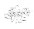
また、アルミニウムからなる正極外部端子部材221の正極固定部222は、実施形態1と異なる。具体的には、図15に示すように、正極端子貫通孔222Kを中心に含み、正極固定部第1面222Aよりも、正極固定部222の内側に1段窪んだ窪み部222Dを有する。この窪み部222Dは、中心に正極端子貫通孔222Kによりくり抜かれた、リング状の底面222Jと、この底面222Jと正極固定部第1面222Aとの間の、テーパ状のテーパ面222Wとを有する。なお、底面222Jは、正極固定部第1面222Aと同じく、正極固定部222の外表面、かつ、外側面に相当する。
Further, the positive
上述の窪み部222Dの内側に配置されてなる正極重畳部227は、かしめ変形により拡径に拡げられて、円板形状に形成されている。従って、正極重畳部227の周縁における端部227Rが、窪み部222Dのテーパ面222Wと突き合わせられている。さらに、レーザビームEBを用いた溶接により、この正極固定部222と正極重畳部227との間に、これらが溶け込んだリング状の正極溶接部PP2が形成されている。
なお、かしめ変形により形成してなる正極重畳部227は、底面222Jに重なりつつ、自身の端部227Rと正極外部端子部材221のテーパ面222Wとが突合せ溶接されてなる。このため、正極外部端子部材221と正極重畳部227との接合強度が、これらをかしめのみで接合してなる場合より増大する。
The positive
The positive
また、本変形形態1にかかる電池201では、正極重畳部227と正極外部端子部材221とを突合せ溶接しているので、正極重畳部227を貫通し、これと正極外部端子部材21の窪み部222D(底面222J)とを貫通溶接した場合に比して、溶接に要するエネルギーを少なくできる。従って、溶接の熱による絶縁部材41の変質を抑制することができる。
また、正極重畳部227と正極外部端子部材221との溶接が確実に行われていることを、その外観から、容易に判別することができる。
Further, in the
Further, it is possible to easily determine from the appearance that the positive
次いで、本変形形態1にかかる電池201の製造方法について、図15〜18を参照しつつ説明する。
図15に、この電池201の正極端子220を構成する、かしめ変形前の未変形正極内部導通部材125、ガスケット45、封口蓋12、絶縁部材41、及び、正極外部端子部材221の分解斜視図を示す。
まず、図15に示すように、未変形正極貫通接続部126を、ガスケット45のガスケット貫通孔45K、封口蓋12のケース貫通孔12K、絶縁部材41の絶縁貫通孔41K、及び、正極外部端子部材221の正極端子貫通孔222Kに、この順に挿通して、その先端側を正極外部端子部材221よりも突出させる。挿通後の未変形正極貫通接続部126とその周囲部分の断面図を図16(a)に示す。
Next, a method for manufacturing the
FIG. 15 is an exploded perspective view of the undeformed positive inner
First, as shown in FIG. 15, the undeformed positive through-
次に、電池201の製造方法のうち、正極端子220側における、重畳部かしめ形成工程について、図16,17を参照しつつ説明する。
図16(a)に示すように、実施形態1と同様、拡径金型151を未変形正極貫通接続部126の変形用穴126Hに向けて、軸線XAに沿って移動させる。またこれと同時に、平面金型152を、正極ケース結合部29Fの下方に当接させて、軸線XAに沿って正極外部端子部材221に向けて移動させる。
これにより、正極外部端子部材221の正極固定部第1面222Aよりも外側では、未変形正極貫通接続部126がカサ状(円錐筒状)に開いた形状とされる(図16(b)参照)。
Next, in the manufacturing method of the
As shown in FIG. 16A, as in the first embodiment, the diameter-enlarged
As a result, the non-deformed positive through-
さらに、図16に示すように、未変形正極貫通接続部126のうち、窪み部222Dの底面222Jより外側(図16中、上方)に位置する部位を、押圧金型153を用いて変形させる。具体的には、押圧金型153を軸線XAに沿って回転させながら、その底面222Jより外側に位置する部位を軸線XAの径方向外側DRに拡径させつつ、その底面222Jに向けて押し倒す。これにより、底面222Jを押圧してなる正極重畳部227ができあがる。
このとき、正極外部端子部材221におけるテーパ面222W、及び、正極重畳部227の端部27Rが、突き合わせた状態で当接し合っており、この部分を突合せ部分JP3とする。
Further, as shown in FIG. 16, a portion of the undeformed positive through-
At this time, the
次に、電池201の製造方法のうち、正極端子220側における溶接工程では、図18に示すように、上述の突合せ部分JP3において、図18中、上方から下方に向けてレーザビームEBを照射して突合せ溶接を行う。これにより、正極重畳部227の端部227Rと正極外部端子部材221のうち正極固定部222のテーパ面222Wを含む部位とが溶融しあって正極溶接部PP2を形成する。
Next, in the manufacturing process of the
本変形形態1にかかる電池201の製造方法では、上述の溶接工程を備えるので、正極重畳部227を貫通し、これと正極外部端子部材21にの窪み部222D(底面222J)とを貫通溶接した場合に比して、溶接に要するエネルギーを少なくすることができる。従って、溶接の熱による絶縁部材41の変質を抑制した電池201を製造できる。
また、正極重畳部227を正極外部端子部材221における窪み部222Dの底面222Jと重ねると共に、正極外部端子部材221におけるテーパ面222Wと正極重畳部227の端部227Rとを突き合わせて、これらを溶接するので、確実に突合せ溶接を行った電池201を製造できる。
Since the manufacturing method of the
Further, the positive
(実施形態2)
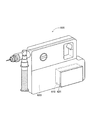
本実施形態2にかかる車両500は、前述した電池1(201)を複数搭載したものである。具体的には、図19に示すように、車両500は、エンジン540、フロントモータ520およびリアモータ530を併用して駆動するハイブリッド自動車である。この車両500は、車体590、エンジン540、これに取り付けられたフロントモータ520、リアモータ530、ケーブル550、インバータ560、及び、複数の電池1(201)を自身の内部に有する組電池510を有している。
(Embodiment 2)
A
本実施形態2にかかる車両500は電池1(201)を搭載しているので、正極及び負極側の各絶縁部材41,41の変質を抑制しつつ、電池1(201)の外部端子部材21,31(221)と内部導通部材25,35(225)との接合強度を確保した車両とすることができる。
Since the
(実施形態3)
また、本実施形態3のハンマードリル600は、前述した電池1(201)を含むバッテリパック610を搭載したものであり、図20に示すように、バッテリパック610、本体620を有する電池搭載機器である。なお、バッテリパック610はハンマードリル600の本体620のうち底部621に可能に収容されている。
(Embodiment 3)
Further, the
本実施形態3にかかるハンマードリル600は電池1(201)を搭載しているので、正極及び負極側の各絶縁部材41,41の変質を抑制しつつ、電池1(201)の外部端子部材21,31(221)と内部導通部材25,35(225)との接合強度を確保した電池搭載機器とすることができる。
Since the
以上において、本発明を実施形態1,2,3及び変形形態1に即して説明したが、本発明は上記実施形態に限定されるものではなく、その要旨を逸脱しない範囲で、適宜変更して適用できることは言うまでもない。
例えば、実施形態1,2および変形形態1では、電池をリチウムイオン二次電池としたが、本発明は、リチウムイオン二次電池に限らず、外部端子部材及び内部導通部材を有する電池であれば、いずれの種類の電池にも適用することができる。また、実施形態1及び変形形態1では、捲回型の発電要素を用いたリチウムイオン二次電池を示したが、複数の正電極板と複数の負電極板とを、セパレータを介して交互に積層してなる積層型の発電要素を用いたリチウムイオン二次電池でも良い。
In the above, the present invention has been described according to the first, second, third, and modified embodiments 1. However, the present invention is not limited to the above-described embodiments, and can be appropriately changed without departing from the gist thereof. Needless to say, this is applicable.
For example, in Embodiments 1 and 2 and Modification 1, the battery is a lithium ion secondary battery. However, the present invention is not limited to a lithium ion secondary battery, but may be any battery having an external terminal member and an internal conduction member. It can be applied to any type of battery. In Embodiment 1 and Modification 1, a lithium ion secondary battery using a wound-type power generation element has been shown. However, a plurality of positive electrode plates and a plurality of negative electrode plates are alternately arranged via separators. A lithium ion secondary battery using stacked power generation elements formed by stacking may be used.
また、実施形態1等では、内部導通部材を発電要素の一方の電極板と直接接合(溶接)して導通するものとしたが、例えば、内部導通部材とは別体の集電部材を電極板に接合し、その集電部材と内部導通部材とを接続して、間接的に導通させても良い。また、樹脂スペーサを絶縁性樹脂からなるもの(絶縁部材41)としたが、例えば、電池の構成上、外部端子部材及び内部導通部材と、電池ケースとの間に、絶縁の必要がない場合には、樹脂スペーサを導通しうる樹脂からなるものとしても良い。さらに、エネルギービームにレーザビームを用いたが、例えば、電子ビーム、イオンビーム等を用いても良い。 In Embodiment 1 and the like, the internal conductive member is directly joined (welded) to one electrode plate of the power generation element to conduct, but for example, a current collecting member separate from the internal conductive member is used as the electrode plate. The current collecting member and the internal conducting member may be connected to each other and indirectly conducted. Further, the resin spacer is made of an insulating resin (insulating member 41). For example, when there is no need for insulation between the external terminal member and the internal conductive member and the battery case due to the configuration of the battery. May be made of a resin capable of conducting the resin spacer. Furthermore, although a laser beam is used as the energy beam, for example, an electron beam, an ion beam, or the like may be used.
また、実施形態1,変形形態1では、内部導通部材と外部端子部材との界面(突き合わせてなる面)の全てを溶融してなる、円弧形状或いは環状の溶接部とした。しかし、例えば、その内部導通部材と外部端子部材との界面の一部を溶融してなる一点状の溶接部としても良い。なおこの場合、その溶接部を1つの界面に対して、単数、又は、複数設けても良い(図21(a)参照)。
また、実施形態1では、外部端子部材において、2つの、或いは、4つの膨出部を配置したが、例えば、単数(1つ)の膨出部の他に、3つ、又は、5つ以上の複数の膨出部を外部端子部材に配置しても良い(図21(b)参照)。さらに、正極外部端子部材と負極外部端子部材とを異なる形態としたが、これらを同一の形態、例えば、互いの膨出部の形態を同一にしても良い。
In the first embodiment and the first modified embodiment, the arc-shaped or annular welded portion is formed by melting all the interfaces (abutting surfaces) between the internal conduction member and the external terminal member. However, for example, a single-point welded portion formed by melting a part of the interface between the internal conductive member and the external terminal member may be used. In this case, one or a plurality of welds may be provided for one interface (see FIG. 21A).
In the first embodiment, two or four bulging portions are arranged in the external terminal member. For example, in addition to a single bulging portion, three or five or more bulging portions are arranged. A plurality of bulging portions may be arranged on the external terminal member (see FIG. 21B). Furthermore, although the positive electrode external terminal member and the negative electrode external terminal member have different forms, they may have the same form, for example, the form of the bulging portions of each other.
1,201 電池
10 電池ケース
21,221 正極外部接続端子(外部接続端子)
21S,221S 外表面
22A 正極固定部第1面(外表面,外側面)
22B,222B 正極固定部第2面(外表面,電池ケースに対向する面)
22T 正極膨出部(膨出部)
22TF 側面
22X 第1平面部(低位部)
22Y 第2平面部(溶接部よりも電池ケース側にある部位)
25,225 正極内部導通部材(内部導通部材)
26,226 正極貫通接続部(貫通接続部)
27,227 正極重畳部(重畳部)
27R,227R 間端部
28 正極端子貫通部(端子貫通部)
31 負極外部接続端子(外部接続端子)
31S 負極外部端子外表面(外表面)
32A 負極固定部第1面(外表面,外側面)
32B 負極固定部第2面(外表面,電池ケースに対向する面)
32T 負極膨出部(膨出部)
32TF 側面
32X 第1平面部(低位部)
32Y 第2平面部(溶接部よりも電池ケース側にある部位)
35 負極内部導通部材(内部導通部材)
36 負極貫通接続部(貫通接続部)
37 負極重畳部(重畳部)
37R 短径端部
38 負極端子貫通部(端子貫通部)
41 絶縁部材(樹脂スペーサ)
50 発電要素
51 正電極板(電極)
52 負電極板(電極)
222A 正極第1面((外部接続端子の)外表面,外側面)
222J 底面((外部接続端子の)外表面,外側面)
500 車両
510 組電池(電池)
600 ハンマードリル(電池搭載機器)
610 バッテリパック(電池)
EB レーザビーム(エネルギービーム)
JP1,JP2,JP3 突合せ部分
PN 負極溶接部(溶接部)
PP1,PP2 正極溶接部(溶接部)
1,201
21S, 221S
22B, 222B Positive electrode fixing portion second surface (outer surface, surface facing the battery case)
22T Positive electrode bulge (bulge)
22Y 2nd plane part (part located on the battery case side from the welded part)
25,225 Positive electrode internal conducting member (internal conducting member)
26,226 Positive electrode through connection (through connection)
27,227 Positive electrode superposition part (superposition part)
27R,
31 Negative external connection terminal (external connection terminal)
31S Negative electrode external terminal outer surface (outer surface)
32A Negative electrode fixing part first surface (outer surface, outer surface)
32B Negative electrode fixing part second surface (outer surface, surface facing the battery case)
32T Negative electrode bulge (bulge)
32Y 2nd plane part (part located on the battery case side from the welded part)
35 Negative Electrode Internal Conducting Member (Internal Conducting Member)
36 Negative electrode through connection (through connection)
37 Negative electrode superposition part (superposition part)
37R Short-
41 Insulating material (resin spacer)
50
52 Negative electrode plate (electrode)
222A Positive electrode first surface (outer surface (outside of connection terminal), outer surface)
222J Bottom (outside surface (outside of external connection terminal), outside surface)
500 Vehicle 510 Assembly battery (battery)
600 Hammer drill (battery equipped equipment)
610 Battery pack (battery)
EB laser beam (energy beam)
JP1, JP2, JP3 Butt part PN Negative electrode welded part (welded part)
PP1, PP2 Positive electrode welded part (welded part)
Claims (9)
上記発電要素を収容してなる電池ケースと、
上記電池ケース内に配置されて、上記発電要素の一方の電極に電気的に導通してなる内部導通部材であって、
上記電池ケースを貫通して、この電池ケースの外部に突出する貫通接続部を有する
内部導通部材と、
上記電池ケースの外部に配置され、上記内部導通部材の上記貫通接続部と溶接された外部端子部材であって、
溶接により上記内部導通部材の上記貫通接続部と共に溶け込んだ溶接部を為してなる
外部端子部材と、
上記電池ケースと上記外部端子部材のうち少なくとも上記溶接部よりも上記電池ケース側の部位との間に介在する樹脂スペーサと、を備える
電池であって、
上記貫通接続部は、
上記外部端子部材の外表面のうち上記電池ケースに対向する面とは逆側に位置する外側面に重なる重畳部を含み、
上記溶接部は、
エネルギービームを用いた、上記重畳部と上記外部端子部材との突合せ溶接により、上記重畳部及び上記外部端子部材内に形成されてなる
電池。 Power generation elements,
A battery case containing the power generation element;
An internal conduction member disposed in the battery case and electrically connected to one electrode of the power generation element,
An internal conduction member that has a through-connection portion that penetrates the battery case and protrudes outside the battery case;
An external terminal member disposed outside the battery case and welded to the through-connection portion of the internal conduction member,
An external terminal member comprising a welded portion melted together with the through-connecting portion of the internal conductive member by welding;
A resin spacer interposed between the battery case and at least the portion of the external terminal member that is closer to the battery case than the welded portion;
The through connection is
Including an overlapping portion overlapping an outer surface located on the opposite side of the outer surface of the external terminal member from the surface facing the battery case;
The weld is
The battery formed in the said superimposition part and the said external terminal member by the butt welding of the said superimposition part and the said external terminal member using an energy beam.
前記外部端子部材は、
前記外側面の側に、周囲の低位部よりも外方に膨出して高位となる膨出部を有し、
前記内部導通部材の前記貫通接続部の前記重畳部は、
上記外部端子部材のうち、上記低位部に重なると共に、
自身の端部が、上記膨出部の側面に突き合わせられ、上記膨出部と溶接されてなる
電池。 The battery according to claim 1,
The external terminal member is
On the side of the outer surface, it has a bulging portion that bulges outward from the surrounding low level portion and becomes high,
The overlapping portion of the through-connection portion of the internal conduction member is
Among the external terminal members, while overlapping with the lower portion,
A battery in which an end portion thereof is abutted against a side surface of the bulging portion and welded to the bulging portion.
前記重畳部は、前記電池ケースに前記貫通接続部を貫通させた後の、上記貫通接続部の一部をかしめ変形させて形成してなる
電池。 The battery according to claim 1 or 2,
The superposition part is a battery formed by caulking and deforming a part of the penetration connection part after the penetration connection part is penetrated through the battery case.
上記発電要素を収容してなる電池ケースと、
上記電池ケース内に配置されて、上記発電要素の一方の電極に電気的に導通してなる内部導通部材であって、
上記電池ケースを貫通して、この電池ケースの外部に突出する貫通接続部を有する
内部導通部材と、
上記電池ケースの外部に配置され、上記内部導通部材の上記貫通接続部と溶接された外部端子部材であって、
溶接により上記内部導通部材の上記貫通接続部と共に溶け込んだ溶接部を為してなる
外部端子部材と、
上記電池ケースと上記外部端子部材のうち少なくとも上記溶接部よりも上記電池ケース側の部位との間に介在する樹脂スペーサと、を備える
電池であって、
上記外部端子部材は、
その外表面のうち上記電池ケースに対向する面とは逆側に位置する外側面の側に、周囲の低位部よりも外方に膨出して高位となる膨出部を有し、
上記貫通接続部は、
上記外部端子部材を貫通する端子貫通部と、
上記端子貫通部よりも、拡径された形態を有し、上記外部端子部材のうち上記低位部の上記外側面に重なると共に、自身の端部が、上記膨出部の側面に突き合わせられた重畳部と、を含み、
上記溶接部は、
エネルギービームを用いた、上記重畳部の端部と上記外部端子部材の上記膨出部との突合せ溶接により、上記重畳部及び上記外部端子部材内に形成されてなり、
上記樹脂スペーサは、
絶縁性樹脂からなり、上記電池ケースと上記外部端子部材との間を絶縁してなる
電池。 Power generation elements,
A battery case containing the power generation element;
An internal conduction member disposed in the battery case and electrically connected to one electrode of the power generation element,
An internal conduction member that has a through-connection portion that penetrates the battery case and protrudes outside the battery case;
An external terminal member disposed outside the battery case and welded to the through-connection portion of the internal conduction member,
An external terminal member comprising a welded portion melted together with the through-connecting portion of the internal conductive member by welding;
A resin spacer interposed between the battery case and at least the portion of the external terminal member that is closer to the battery case than the welded portion;
The external terminal member is
Of the outer surface, on the side of the outer surface located on the opposite side to the surface facing the battery case, has a bulging portion that bulges outward from the surrounding lower level portion and becomes higher,
The through connection is
A terminal penetrating portion penetrating the external terminal member;
It has a form that is larger in diameter than the terminal penetrating portion, and overlaps with the outer side surface of the lower portion of the external terminal member, and its end is abutted against the side surface of the bulging portion And
The weld is
By using an energy beam, the butt welding of the end of the overlapping portion and the bulging portion of the external terminal member is formed in the overlapping portion and the external terminal member,
The resin spacer is
A battery made of an insulating resin and insulated between the battery case and the external terminal member.
上記発電要素を収容してなる電池ケースと、
上記電池ケース内に配置されて、上記発電要素の一方の電極に電気的に導通してなる内部導通部材であって、
上記電池ケースを貫通して、この電池ケースの外部に突出する貫通接続部を有する
内部導通部材と、
上記電池ケースの外部に配置され、上記内部導通部材の上記貫通接続部と溶接された外部端子部材であって、
溶接により上記内部導通部材の上記貫通接続部と共に溶け込んだ溶接部を為してなる
外部端子部材と、
上記電池ケースと上記外部端子部材のうち少なくとも上記溶接部よりも上記電池ケース側の部位との間に介在する樹脂スペーサと、を備える
電池の製造方法であって、
上記貫通接続部は、
上記外部端子部材の外表面のうち上記電池ケースに対向する面とは逆側に位置する外側面に重なる重畳部を含み、
エネルギービームを、上記重畳部と上記外部端子部材との突合せ部分に照射して、上記重畳部及び上記外部端子部材内に上記溶接部を形成形態に、溶接する溶接工程、を備える
電池の製造方法。 Power generation elements,
A battery case containing the power generation element;
An internal conduction member disposed in the battery case and electrically connected to one electrode of the power generation element,
An internal conduction member that has a through-connection portion that penetrates the battery case and protrudes outside the battery case;
An external terminal member disposed outside the battery case and welded to the through-connection portion of the internal conduction member,
An external terminal member comprising a welded portion melted together with the through-connecting portion of the internal conductive member by welding;
A resin spacer interposed between the battery case and at least the portion of the external terminal member that is closer to the battery case than the welded portion, and a battery manufacturing method comprising:
The through connection is
Including an overlapping portion overlapping an outer surface located on the opposite side of the outer surface of the external terminal member from the surface facing the battery case;
A battery manufacturing method comprising: a welding step of irradiating an abutting portion between the overlapping portion and the external terminal member with an energy beam and welding the welded portion in a form of forming the overlapping portion and the external terminal member. .
前記外部端子部材は、
前記外側面の側に、周囲の低位部よりも外方に膨出して高位となる膨出部を有し、
前記内部導通部材の前記貫通接続部の前記重畳部は、
上記外部端子部材のうち、上記低位部に重なると共に、
自身の端部が、上記膨出部の側面に突き合わせられてなり、
前記溶接工程は、
上記重畳部の上記端部と上記外部端子部材の上記膨出部とを溶接する
電池の製造方法。 A battery manufacturing method according to claim 7,
The external terminal member is
On the side of the outer surface, it has a bulging portion that bulges outward from the surrounding low level portion and becomes high,
The overlapping portion of the through-connection portion of the internal conduction member is
Among the external terminal members, while overlapping with the lower portion,
Its own end is abutted against the side of the bulge,
The welding process includes
A battery manufacturing method for welding the end portion of the overlapping portion and the bulging portion of the external terminal member.
前記溶接工程に先立ち、
前記電池ケースに前記貫通接続部を貫通させた後に、上記貫通接続部の一部をかしめ変形して、前記重畳部を形成する重畳部かしめ形成工程、を備える
電池の製造方法。 A method of manufacturing a battery according to claim 7 or claim 8,
Prior to the welding process,
A battery manufacturing method comprising: an overlapping portion caulking forming step of forming the overlapping portion by caulking and deforming a part of the through connecting portion after passing the through connecting portion through the battery case.
Priority Applications (1)
| Application Number | Priority Date | Filing Date | Title |
|---|---|---|---|
| JP2008192446A JP5168007B2 (en) | 2008-07-25 | 2008-07-25 | Battery, vehicle, battery-mounted device, and battery manufacturing method |
Applications Claiming Priority (1)
| Application Number | Priority Date | Filing Date | Title |
|---|---|---|---|
| JP2008192446A JP5168007B2 (en) | 2008-07-25 | 2008-07-25 | Battery, vehicle, battery-mounted device, and battery manufacturing method |
Publications (2)
| Publication Number | Publication Date |
|---|---|
| JP2010033766A true JP2010033766A (en) | 2010-02-12 |
| JP5168007B2 JP5168007B2 (en) | 2013-03-21 |
Family
ID=41738011
Family Applications (1)
| Application Number | Title | Priority Date | Filing Date |
|---|---|---|---|
| JP2008192446A Active JP5168007B2 (en) | 2008-07-25 | 2008-07-25 | Battery, vehicle, battery-mounted device, and battery manufacturing method |
Country Status (1)
| Country | Link |
|---|---|
| JP (1) | JP5168007B2 (en) |
Cited By (31)
| Publication number | Priority date | Publication date | Assignee | Title |
|---|---|---|---|---|
| JP2010073336A (en) * | 2008-09-16 | 2010-04-02 | Toyota Motor Corp | Battery, and battery manufacturing method |
| JP2010277797A (en) * | 2009-05-27 | 2010-12-09 | Toyota Motor Corp | Battery, vehicle, and battery using device |
| WO2012014510A1 (en) * | 2010-07-27 | 2012-02-02 | 日立ビークルエナジー株式会社 | Secondary cell |
| EP2463937A2 (en) | 2010-12-10 | 2012-06-13 | GS Yuasa International Ltd. | Storage element and terminal fabricating method |
| JP2012174684A (en) * | 2011-02-18 | 2012-09-10 | Sb Limotive Co Ltd | Secondary battery and method of manufacturing the same |
| WO2013031761A1 (en) * | 2011-08-29 | 2013-03-07 | 株式会社リチウムエナジージャパン | Connection body, method for manufacturing connection body, power storage element and method for manufacturing power storage element |
| JP2013157130A (en) * | 2012-01-27 | 2013-08-15 | Sanyo Electric Co Ltd | Rectangular secondary battery |
| JP2013182724A (en) * | 2012-02-29 | 2013-09-12 | Sanyo Electric Co Ltd | Square type secondary battery |
| CN103515569A (en) * | 2012-06-29 | 2014-01-15 | 丰田自动车株式会社 | Battery, production method for battery, and mask member for production of battery |
| JP2014017081A (en) * | 2012-07-06 | 2014-01-30 | Hitachi Vehicle Energy Ltd | Secondary battery |
| US8790821B2 (en) | 2010-05-17 | 2014-07-29 | Gs Yuasa International Ltd. | Battery |
| JP2014143153A (en) * | 2013-01-25 | 2014-08-07 | Toyota Industries Corp | Power storage module |
| JP2014165155A (en) * | 2013-02-28 | 2014-09-08 | Sanyo Electric Co Ltd | Square secondary battery |
| JP2014167846A (en) * | 2013-02-28 | 2014-09-11 | Sanyo Electric Co Ltd | Square secondary battery |
| JP2014211967A (en) * | 2013-04-17 | 2014-11-13 | トヨタ自動車株式会社 | Terminal for battery |
| JP2015106501A (en) * | 2013-11-29 | 2015-06-08 | トヨタ自動車株式会社 | Method of manufacturing secondary battery |
| JP2015153521A (en) * | 2014-02-12 | 2015-08-24 | トヨタ自動車株式会社 | Method of manufacturing secondary battery |
| WO2016020996A1 (en) * | 2014-08-06 | 2016-02-11 | 日立オートモティブシステムズ株式会社 | Rectangular secondary battery |
| JP2016096038A (en) * | 2014-11-14 | 2016-05-26 | トヨタ自動車株式会社 | Terminal component and method of manufacturing terminal component |
| JP2017073236A (en) * | 2015-10-05 | 2017-04-13 | トヨタ自動車株式会社 | Battery manufacturing method |
| JP2017084585A (en) * | 2015-10-27 | 2017-05-18 | トヨタ自動車株式会社 | Battery and battery manufacturing method |
| CN106808075A (en) * | 2016-07-19 | 2017-06-09 | 东莞理工学院 | A kind of button cell automatic butt-welding device |
| CN107046109A (en) * | 2016-02-09 | 2017-08-15 | 丰田自动车株式会社 | Battery |
| JP2017228418A (en) * | 2016-06-22 | 2017-12-28 | プライムアースEvエナジー株式会社 | Method of manufacturing cell and cell |
| US9905829B2 (en) | 2013-09-24 | 2018-02-27 | Gs Yuasa International Ltd. | Energy storage apparatus |
| WO2019025937A1 (en) * | 2017-07-31 | 2019-02-07 | リチウム エナジー アンド パワーゲゼルシャフト ミット· べシュレンクテル ハフッング ウント コンパ二ー マンディトゲゼルシャフト | Energy storage device |
| JP2019036412A (en) * | 2017-08-10 | 2019-03-07 | トヨタ自動車株式会社 | Sealed battery |
| US10269502B2 (en) | 2015-08-25 | 2019-04-23 | Gs Yuasa International Ltd. | Energy storage device including a conductive member penetrating a container and a fixing member covering the conductive member |
| JP2019087453A (en) * | 2017-11-08 | 2019-06-06 | トヨタ自動車株式会社 | Power storage device and manufacturing method of the same |
| CN110544758A (en) * | 2018-05-29 | 2019-12-06 | 罗伯特·博世有限公司 | method for connecting electrochemical cells, battery module and system for producing same |
| CN111615770A (en) * | 2018-09-14 | 2020-09-01 | 重庆金康新能源汽车有限公司 | Bipolar cover for a battery cell of an electric vehicle |
Citations (8)
| Publication number | Priority date | Publication date | Assignee | Title |
|---|---|---|---|---|
| JP2000113865A (en) * | 1998-10-02 | 2000-04-21 | At Battery:Kk | Secondary battery |
| JP2001093486A (en) * | 1999-09-28 | 2001-04-06 | Sanyo Electric Co Ltd | Square-type sealed battery and manufacturing method of the same |
| JP2001126690A (en) * | 1999-10-22 | 2001-05-11 | Sanyo Electric Co Ltd | Battery set |
| JP2004014173A (en) * | 2002-06-04 | 2004-01-15 | Japan Storage Battery Co Ltd | Battery and manufacturing method for battery |
| JP2009087693A (en) * | 2007-09-28 | 2009-04-23 | Sanyo Electric Co Ltd | Sealed battery and its manufacturing method |
| JP2009087736A (en) * | 2007-09-28 | 2009-04-23 | Toshiba Corp | Method for manufacturing terminal device |
| JP2009283256A (en) * | 2008-05-21 | 2009-12-03 | Toyota Motor Corp | Power supply device and power supply device manufacturing method |
| JP2010027546A (en) * | 2008-07-24 | 2010-02-04 | Toshiba Corp | Battery device |
-
2008
- 2008-07-25 JP JP2008192446A patent/JP5168007B2/en active Active
Patent Citations (8)
| Publication number | Priority date | Publication date | Assignee | Title |
|---|---|---|---|---|
| JP2000113865A (en) * | 1998-10-02 | 2000-04-21 | At Battery:Kk | Secondary battery |
| JP2001093486A (en) * | 1999-09-28 | 2001-04-06 | Sanyo Electric Co Ltd | Square-type sealed battery and manufacturing method of the same |
| JP2001126690A (en) * | 1999-10-22 | 2001-05-11 | Sanyo Electric Co Ltd | Battery set |
| JP2004014173A (en) * | 2002-06-04 | 2004-01-15 | Japan Storage Battery Co Ltd | Battery and manufacturing method for battery |
| JP2009087693A (en) * | 2007-09-28 | 2009-04-23 | Sanyo Electric Co Ltd | Sealed battery and its manufacturing method |
| JP2009087736A (en) * | 2007-09-28 | 2009-04-23 | Toshiba Corp | Method for manufacturing terminal device |
| JP2009283256A (en) * | 2008-05-21 | 2009-12-03 | Toyota Motor Corp | Power supply device and power supply device manufacturing method |
| JP2010027546A (en) * | 2008-07-24 | 2010-02-04 | Toshiba Corp | Battery device |
Cited By (50)
| Publication number | Priority date | Publication date | Assignee | Title |
|---|---|---|---|---|
| JP2010073336A (en) * | 2008-09-16 | 2010-04-02 | Toyota Motor Corp | Battery, and battery manufacturing method |
| JP2010277797A (en) * | 2009-05-27 | 2010-12-09 | Toyota Motor Corp | Battery, vehicle, and battery using device |
| US8790821B2 (en) | 2010-05-17 | 2014-07-29 | Gs Yuasa International Ltd. | Battery |
| WO2012014510A1 (en) * | 2010-07-27 | 2012-02-02 | 日立ビークルエナジー株式会社 | Secondary cell |
| JP2012028246A (en) * | 2010-07-27 | 2012-02-09 | Hitachi Vehicle Energy Ltd | Secondary battery |
| EP2463937A2 (en) | 2010-12-10 | 2012-06-13 | GS Yuasa International Ltd. | Storage element and terminal fabricating method |
| US8945760B2 (en) | 2010-12-10 | 2015-02-03 | Gs Yuasa International Ltd. | Storage element and terminal fabricating method |
| EP3671889A1 (en) | 2010-12-10 | 2020-06-24 | GS Yuasa International Ltd. | Storage element |
| KR101921157B1 (en) | 2010-12-10 | 2019-02-13 | 가부시키가이샤 지에스 유아사 | Storage element and terminal fabricating method |
| EP3457454A1 (en) | 2010-12-10 | 2019-03-20 | GS Yuasa International Ltd. | Storage element and terminal fabricating method |
| JP2012174684A (en) * | 2011-02-18 | 2012-09-10 | Sb Limotive Co Ltd | Secondary battery and method of manufacturing the same |
| US9698404B2 (en) | 2011-08-29 | 2017-07-04 | Gs Yuasa International Ltd. | Connecting body, manufacturing method of connecting body, electric storage device, and manufacturing method of electric storage device |
| CN103582965A (en) * | 2011-08-29 | 2014-02-12 | 锂能源日本有限公司 | Connection body, method for manufacturing connection body, power storage element and method for manufacturing power storage element |
| KR20140053012A (en) * | 2011-08-29 | 2014-05-07 | 가부시키가이샤 리튬 에너지 재팬 | Connection body, method for manufacturing connection body, power storage element and method for manufacturing power storage element |
| KR102115861B1 (en) | 2011-08-29 | 2020-05-27 | 가부시키가이샤 지에스 유아사 | Connection body, method for manufacturing connection body, power storage element and method for manufacturing power storage element |
| JPWO2013031761A1 (en) * | 2011-08-29 | 2015-03-23 | 株式会社リチウムエナジージャパン | Connection body, method for manufacturing connection body, power storage element, and method for manufacturing power storage element |
| WO2013031761A1 (en) * | 2011-08-29 | 2013-03-07 | 株式会社リチウムエナジージャパン | Connection body, method for manufacturing connection body, power storage element and method for manufacturing power storage element |
| US8906545B2 (en) | 2012-01-27 | 2014-12-09 | Sanyo Electric Co., Ltd. | Prismatic secondary battery |
| JP2013157130A (en) * | 2012-01-27 | 2013-08-15 | Sanyo Electric Co Ltd | Rectangular secondary battery |
| US9225001B2 (en) | 2012-02-29 | 2015-12-29 | Sanyo Electric Co., Ltd. | Prismatic secondary battery |
| JP2013182724A (en) * | 2012-02-29 | 2013-09-12 | Sanyo Electric Co Ltd | Square type secondary battery |
| JP2014011073A (en) * | 2012-06-29 | 2014-01-20 | Toyota Motor Corp | Battery, manufacturing method of the battery and mask member for manufacturing the battery |
| CN103515569A (en) * | 2012-06-29 | 2014-01-15 | 丰田自动车株式会社 | Battery, production method for battery, and mask member for production of battery |
| JP2014017081A (en) * | 2012-07-06 | 2014-01-30 | Hitachi Vehicle Energy Ltd | Secondary battery |
| JP2014143153A (en) * | 2013-01-25 | 2014-08-07 | Toyota Industries Corp | Power storage module |
| JP2014167846A (en) * | 2013-02-28 | 2014-09-11 | Sanyo Electric Co Ltd | Square secondary battery |
| JP2014165155A (en) * | 2013-02-28 | 2014-09-08 | Sanyo Electric Co Ltd | Square secondary battery |
| US9680145B2 (en) | 2013-02-28 | 2017-06-13 | Sanyo Electric Co., Ltd. | Prismatic secondary battery |
| US9653722B2 (en) | 2013-02-28 | 2017-05-16 | Sanyo Electric Co., Ltd. | Prismatic secondary battery |
| JP2014211967A (en) * | 2013-04-17 | 2014-11-13 | トヨタ自動車株式会社 | Terminal for battery |
| US9905829B2 (en) | 2013-09-24 | 2018-02-27 | Gs Yuasa International Ltd. | Energy storage apparatus |
| JP2015106501A (en) * | 2013-11-29 | 2015-06-08 | トヨタ自動車株式会社 | Method of manufacturing secondary battery |
| JP2015153521A (en) * | 2014-02-12 | 2015-08-24 | トヨタ自動車株式会社 | Method of manufacturing secondary battery |
| JPWO2016020996A1 (en) * | 2014-08-06 | 2017-05-25 | 日立オートモティブシステムズ株式会社 | Prismatic secondary battery |
| WO2016020996A1 (en) * | 2014-08-06 | 2016-02-11 | 日立オートモティブシステムズ株式会社 | Rectangular secondary battery |
| JP2016096038A (en) * | 2014-11-14 | 2016-05-26 | トヨタ自動車株式会社 | Terminal component and method of manufacturing terminal component |
| US10269502B2 (en) | 2015-08-25 | 2019-04-23 | Gs Yuasa International Ltd. | Energy storage device including a conductive member penetrating a container and a fixing member covering the conductive member |
| JP2017073236A (en) * | 2015-10-05 | 2017-04-13 | トヨタ自動車株式会社 | Battery manufacturing method |
| US10109824B2 (en) | 2015-10-27 | 2018-10-23 | Toyota Jidosha Kabushiki Kaisha | Battery and manufacturing method for battery |
| JP2017084585A (en) * | 2015-10-27 | 2017-05-18 | トヨタ自動車株式会社 | Battery and battery manufacturing method |
| CN107046109A (en) * | 2016-02-09 | 2017-08-15 | 丰田自动车株式会社 | Battery |
| JP2017142929A (en) * | 2016-02-09 | 2017-08-17 | トヨタ自動車株式会社 | battery |
| JP2017228418A (en) * | 2016-06-22 | 2017-12-28 | プライムアースEvエナジー株式会社 | Method of manufacturing cell and cell |
| CN106808075A (en) * | 2016-07-19 | 2017-06-09 | 东莞理工学院 | A kind of button cell automatic butt-welding device |
| WO2019025937A1 (en) * | 2017-07-31 | 2019-02-07 | リチウム エナジー アンド パワーゲゼルシャフト ミット· べシュレンクテル ハフッング ウント コンパ二ー マンディトゲゼルシャフト | Energy storage device |
| JP2019036412A (en) * | 2017-08-10 | 2019-03-07 | トヨタ自動車株式会社 | Sealed battery |
| JP2019087453A (en) * | 2017-11-08 | 2019-06-06 | トヨタ自動車株式会社 | Power storage device and manufacturing method of the same |
| CN110544758A (en) * | 2018-05-29 | 2019-12-06 | 罗伯特·博世有限公司 | method for connecting electrochemical cells, battery module and system for producing same |
| CN110544758B (en) * | 2018-05-29 | 2023-04-07 | 罗伯特·博世有限公司 | Method for connecting electrochemical cells, battery module and system for producing same |
| CN111615770A (en) * | 2018-09-14 | 2020-09-01 | 重庆金康新能源汽车有限公司 | Bipolar cover for a battery cell of an electric vehicle |
Also Published As
| Publication number | Publication date |
|---|---|
| JP5168007B2 (en) | 2013-03-21 |
Similar Documents
| Publication | Publication Date | Title |
|---|---|---|
| JP5168007B2 (en) | Battery, vehicle, battery-mounted device, and battery manufacturing method | |
| JP5868265B2 (en) | Single cells and batteries | |
| JP6093874B2 (en) | Prismatic secondary battery | |
| JP5146065B2 (en) | Batteries, assembled batteries, vehicles, and battery-equipped devices | |
| US9680145B2 (en) | Prismatic secondary battery | |
| JP5213404B2 (en) | Sealed battery and manufacturing method thereof | |
| US9819027B2 (en) | Method for producing battery and battery | |
| JP6427462B2 (en) | Square secondary battery | |
| EP2378593B1 (en) | Battery module | |
| JP5103489B2 (en) | Sealed battery | |
| JP4588331B2 (en) | Square battery and manufacturing method thereof | |
| WO2012014510A1 (en) | Secondary cell | |
| JP5326125B2 (en) | Nonaqueous electrolyte secondary battery | |
| JP5206264B2 (en) | Battery and battery manufacturing method | |
| US10811668B2 (en) | Secondary battery | |
| JP5342090B1 (en) | Electricity storage element | |
| JP2013157130A (en) | Rectangular secondary battery | |
| US10797297B2 (en) | Secondary battery | |
| JPWO2012169055A1 (en) | Secondary battery | |
| JP2012186005A (en) | Battery and battery manufacturing method | |
| JP2014102895A (en) | Closed container manufacturing method | |
| JP5619033B2 (en) | Sealed battery and manufacturing method thereof | |
| KR101483425B1 (en) | Secondary Battery Having Novel Electrode Tap-Lead Joint Portion | |
| JP6192992B2 (en) | Prismatic secondary battery | |
| JP2010049913A (en) | Manufacturing method of sealed battery |
Legal Events
| Date | Code | Title | Description |
|---|---|---|---|
| A621 | Written request for application examination |
Free format text: JAPANESE INTERMEDIATE CODE: A621 Effective date: 20101007 |
|
| A977 | Report on retrieval |
Free format text: JAPANESE INTERMEDIATE CODE: A971007 Effective date: 20120808 |
|
| A131 | Notification of reasons for refusal |
Free format text: JAPANESE INTERMEDIATE CODE: A131 Effective date: 20120911 |
|
| A521 | Written amendment |
Free format text: JAPANESE INTERMEDIATE CODE: A523 Effective date: 20121105 |
|
| TRDD | Decision of grant or rejection written | ||
| A01 | Written decision to grant a patent or to grant a registration (utility model) |
Free format text: JAPANESE INTERMEDIATE CODE: A01 Effective date: 20121127 |
|
| A61 | First payment of annual fees (during grant procedure) |
Free format text: JAPANESE INTERMEDIATE CODE: A61 Effective date: 20121210 |
|
| R151 | Written notification of patent or utility model registration |
Ref document number: 5168007 Country of ref document: JP Free format text: JAPANESE INTERMEDIATE CODE: R151 |
|
| FPAY | Renewal fee payment (event date is renewal date of database) |
Free format text: PAYMENT UNTIL: 20160111 Year of fee payment: 3 |