JP2010032860A - Alignment layer and method of manufacturing the same, alignment substrate and method of manufacturing the same, and liquid crystal display element - Google Patents
Alignment layer and method of manufacturing the same, alignment substrate and method of manufacturing the same, and liquid crystal display element Download PDFInfo
- Publication number
- JP2010032860A JP2010032860A JP2008196013A JP2008196013A JP2010032860A JP 2010032860 A JP2010032860 A JP 2010032860A JP 2008196013 A JP2008196013 A JP 2008196013A JP 2008196013 A JP2008196013 A JP 2008196013A JP 2010032860 A JP2010032860 A JP 2010032860A
- Authority
- JP
- Japan
- Prior art keywords
- liquid crystal
- alignment
- layer
- crystal molecules
- alignment film
- Prior art date
- Legal status (The legal status is an assumption and is not a legal conclusion. Google has not performed a legal analysis and makes no representation as to the accuracy of the status listed.)
- Pending
Links
Images


Landscapes
- Liquid Crystal (AREA)
Abstract
Description
本発明は、液晶表示素子において表示用液晶分子の配向を制御する配向膜及びその製造方法、その配向膜を備えた配向基板及びその製造方法、並びに液晶表示素子に関するものである。 The present invention relates to an alignment film that controls the alignment of liquid crystal molecules for display in a liquid crystal display element, a manufacturing method thereof, an alignment substrate including the alignment film, a manufacturing method thereof, and a liquid crystal display element.
今日、液晶表示装置は、携帯電話や液晶テレビなどの電子機器の表示部として、また、パーソナルコンピュータ(Personal Computer;PC)用の表示装置などとして、広く用いられている。フルカラー表示装置として一般に用いられている透過型液晶表示装置は、カラーフィルタを備えた透過型液晶表示素子(液晶表示パネル)と、その背面側を白色光で照射するバックライト装置からなり、照射光が液晶表示素子を透過する透過率を制御することによって画像を表示する。 Today, liquid crystal display devices are widely used as display units for electronic devices such as mobile phones and liquid crystal televisions, and as display devices for personal computers (PCs). A transmissive liquid crystal display device generally used as a full-color display device includes a transmissive liquid crystal display element (liquid crystal display panel) having a color filter and a backlight device that irradiates the back side with white light. Displays an image by controlling the transmittance through the liquid crystal display element.
図12は、従来の液晶表示素子の基本的な構成を示す部分断面図である。液晶表示素子100では、液晶層101と、液晶層101を挟んで対向する一対の透明基板102aおよび102bとによって液晶セル105が形成され、透明基板102aおよび102bの外面側に一対の偏光板106aおよび106bがそれぞれ配置されている。
FIG. 12 is a partial cross-sectional view showing a basic configuration of a conventional liquid crystal display element. In the liquid crystal display element 100, a liquid crystal cell 105 is formed by a
透明基板102aおよび102bはガラス基板などからなり、透明基板102aの内面には、透明電極103aおよび配向膜104aなどが形成され、透明基板102bの内面には、(図示省略した)R(赤)、G(緑)、B(青)の三原色カラーフィルタ、透明電極103b、および配向膜104bなどが形成されている。透明電極103aおよび103bは、例えばITO(Indium Tin Oxide)などからなる。配向膜104aおよび104bは液晶層101に接するように設けられている。
The
偏光板106aおよび106bは、それぞれ、偏光フィルムと2枚の透明保護膜などからなる。偏光フィルムは、通常、一軸延伸されたポリビニルアルコールなどのフィルムと、そのフィルムに保持されたヨウ素または二色性染料などからなる。そして、その両側に透明保護膜としてTAC(トリアセチルセルロース)膜などが貼り合わされて用いられる。 Each of the polarizing plates 106a and 106b includes a polarizing film and two transparent protective films. The polarizing film is usually composed of a uniaxially stretched film such as polyvinyl alcohol and iodine or a dichroic dye held on the film. And a TAC (triacetyl cellulose) film | membrane etc. are bonded together and used as a transparent protective film on the both sides.
液晶表示素子100では、電界が印加されていないときに、液晶層101の液晶分子に透明基板102aと102bとの間で特定の規則的な配向状態をとらせておく。そして、この液晶分子に電界を作用させることによって、液晶分子の配向状態を変化させ、液晶表示素子100の光透過率を変化させる。従って、電界が印加されていないときに液晶分子に特定の配向状態をとらせておく配向技術が、液晶表示素子の善し悪しを決める鍵の1つになっている。
In the liquid crystal display element 100, when an electric field is not applied, the liquid crystal molecules of the
上記の配向技術や、電界によって液晶分子の配向状態を変化させる方法などの違いによって、液晶表示素子100には様々な動作モードがあり、例えば、TN(Twisted Nematic)モード、IPS(In-Plane Switching)モード、ECB(Electrically Controlled Birefringence)モード、OCB(Optically Compensatory Bend)モード、およびVA(Vertical Alignment)モードなどが提案されている(例えば、山崎照彦、川上英昭、堀浩雄 監修、カラーTFT液晶ディスプレイ(改訂版)、共立出版(2005)参照。)。 The liquid crystal display element 100 has various operation modes depending on the alignment technique and the method of changing the alignment state of liquid crystal molecules by an electric field, such as TN (Twisted Nematic) mode, IPS (In-Plane Switching). ) Mode, ECB (Electrically Controlled Birefringence) mode, OCB (Optically Compensatory Bend) mode, and VA (Vertical Alignment) mode are proposed (for example, supervised by Teruhiko Yamazaki, Hideaki Kawakami, Hiroo Hori, color TFT liquid crystal display ( Revised version), see Kyoritsu Publishing (2005).)
図13(a)は、TNモード、IPSモード、ECBモード、およびOCBモードなどにおいて用いられる配向技術を示す説明図であり、水平配向膜114に接してホモジニアス配向している液晶分子の配向状態を示している。これらの動作モードでは、電界が印加されていないときには、水平配向膜114によって、これに接している液晶分子110の長軸方向を、透明基板102の面に対しほぼ平行に、且つ、一定方向に揃って並ぶように水平配向させる。この場合、図13(a)に示すように、水平配向している液晶分子110の配向方向が基板面に対してわずかに傾いている(プレチルトしている)ことが重要である。このプレチルトが存在することによって、電界を作用させたときに液晶分子110が反対方向に傾くリバースチルトを防止し、液晶表示素子としての良好な動作特性や光学特性を実現することができる。
FIG. 13A is an explanatory diagram showing an alignment technique used in the TN mode, the IPS mode, the ECB mode, the OCB mode, and the like, and shows the alignment state of liquid crystal molecules that are in homogeneous alignment in contact with the horizontal alignment film 114. Show. In these operation modes, when no electric field is applied, the major axis direction of the
このように上記の各動作モードにおいて、水平配向膜114は必須のものである。現在広く用いられている水平配向膜114は、基板上にポリイミドなどの有機高分子樹脂膜を形成し、その表面をレーヨンやナイロンの布などで一定方向に強く擦るラビング処理を施して作製される。ラビング処理された高分子樹脂膜に対し、液晶分子110は、長軸方向がラビング方向と平行になるように配向する。ポリイミド膜は、ラビング処理によって数度程度のプレチルト角が得られるので、好適に用いられる。
As described above, the horizontal alignment film 114 is indispensable in each operation mode. The currently widely used horizontal alignment film 114 is formed by forming an organic polymer resin film such as polyimide on a substrate and performing a rubbing process in which the surface is strongly rubbed with a rayon or nylon cloth in a certain direction. . The
しかしながら、ラビング処理によって実現できるプレチルト角は、高分子樹脂の材料特性によって狭い範囲に限定され、再現性のよいプレチルト角を実現するには、ラビング状態を精密に制御する必要がある。 However, the pretilt angle that can be realized by the rubbing process is limited to a narrow range depending on the material characteristics of the polymer resin, and in order to realize a pretilt angle with good reproducibility, it is necessary to precisely control the rubbing state.
そこで、ラビング処理によらない水平配向膜の製造方法が提案されている。例えば、後述の特許文献1では、約10゜程度のプレチルト角を再現性よく発現させる技術が提案され、この技術を用いた液晶セルの製造方法が提案されている。この製造方法では、まず、紫外線を透過し得る基板主面上に、紫外線吸収剤と光重合開始剤と重合性液晶性モノマーからなるメソゲン層を形成する。次に、重合性液晶性モノマーが液晶状態に保たれる所定温度に基板を保ち、所望の方向の磁場を印加しつつ、基板を通してメソゲン層に紫外線を照射することによって、重合性液晶性モノマーを重合させ、高分子層を形成する。次に、その表面の未反応物を有機溶剤で洗浄除去し、高分子層だけを残し、配向膜を得る。この後、配向膜が対向するように一対の基板を配置し、所望の間隙を保って貼合わせ、この間隙に液晶を充填することによって、液晶セルを作製する。メソゲン層は、低分子液晶と紫外線吸収剤と光重合開始剤と重合性液晶性モノマーからなる層としてもよく、磁場と電場を併用してもよいとされている。
Therefore, a method for producing a horizontal alignment film that does not involve rubbing has been proposed. For example, in
また、基板の主面を予めシランカップラー層や有極性有機樹脂層で被覆しておくと、その上に均一なメソゲン層を形成するのに効果的であったと記載されている。実際、特許文献2では、プレチルト角が具体的に示されているすべての実施例で、基板の主面をシランカップラー層または有極性有機樹脂層で被覆し、その上にメソゲン層を形成している。
Further, it is described that when the main surface of the substrate is previously coated with a silane coupler layer or a polar organic resin layer, it is effective to form a uniform mesogen layer thereon. In fact, in
図13(b)は、特許文献1の実施例1に記載されていた下記の記述をもとにして、水平配向膜とその近傍を図示した概略図である。実施例1では、まず、ITO透明電極を設けた低アルカリガラス基板102a(または102b)の一主面にビニルトリメトキシシランからなるシランカップラー層115を形成した後、その上に4−アクリロイルオキシ−4’−ブチル−ビシクロヘキシルなどの重合性液晶性モノマー116に少量のベンゾフェノン系光重合開始剤を加えたアセトン溶液を塗布した後、風乾して、メソゲン層を形成した。偏光顕微鏡観察によれば、メソゲン層は液晶相を示していた。
FIG. 13B is a schematic diagram illustrating the horizontal alignment film and the vicinity thereof based on the following description described in Example 1 of
次に、基板102の法線と磁束のなす角が約65゜(基板面と磁束のなす角が約25゜)になるように磁場を印加して重合性液晶性モノマー116を配向させ、この状態で基板102の裏面側から紫外線を照射して、メソゲン層の少なくとも一部を重合させ、高分子層を形成した。この後、アセトンに数分間浸漬し、未反応物を除去して、水平配向膜117を得た。この水平配向膜117にはリタデーションが存在することを確認した。
Next, the polymerizable liquid crystal monomer 116 is oriented by applying a magnetic field so that the angle between the normal line of the
この後、一対の基板を、水平配向膜117が対向するように、また、水平配向膜117を形成したときに加えた磁場の方向が反平行となるように配置し、一定(10μm)の間隙を保って貼り合わせ、この間隙にメルク社製のネマチック液晶ZLI−2293を充填して、液晶セルを作製した。この液晶セルにおけるプレチルト角は、23.2〜23.5゜であった。 Thereafter, the pair of substrates are arranged so that the horizontal alignment film 117 faces each other, and the direction of the magnetic field applied when the horizontal alignment film 117 is formed is antiparallel, and a constant (10 μm) gap is provided. And a nematic liquid crystal ZLI-2293 manufactured by Merck Co., Ltd. was filled in the gap to prepare a liquid crystal cell. The pretilt angle in this liquid crystal cell was 23.2 to 23.5 °.
特許文献1には、この他に、基板面と磁束とがなす角が5°、10°、および15°であるとき、それぞれ、4.9〜5.1°、9.4〜9.7°、および13.6〜13.8°のプレチルト角を発現する水平配向膜が得られた実施例が述べられている。
In addition to this, in
一方、図14は、VAモードにおいて用いられる配向技術を示す部分断面図である。図14(a)は、電界が印加されていないときに、ホメオトロピック配向している液晶分子120の配向状態を示している。VAモードでは、液晶層101を構成する液晶分子120として、異種物質との界面において界面に垂直に配向する性質をもつ液晶分子を選択する。この結果、電界が印加されていないときには、液晶分子120が基板面に対し垂直に配向した状態(ホメオトロピック配向状態)をとらせることができる。
On the other hand, FIG. 14 is a partial cross-sectional view showing an alignment technique used in the VA mode. FIG. 14A shows the alignment state of the liquid crystal molecules 120 that are homeotropically aligned when no electric field is applied. In the VA mode, as the liquid crystal molecules 120 constituting the
さらに、液晶分子120として、誘電率異方性が負で、電界を作用させた時に分子の長軸が電界方向と略垂直になるように配向しようとする性質をもつ分子を選択して用いる。この結果、電界を作用させたときに、図14(b)に示すように、液晶分子120が、長軸が電界方向と略垂直に配向した状態(基板面に平行に配向した状態)に近づくように、配向方向を変化させるようにすることができる。 Further, as the liquid crystal molecule 120, a molecule having a property that the dielectric anisotropy is negative and the molecule is oriented so that the major axis of the molecule is substantially perpendicular to the electric field direction when an electric field is applied is selected and used. As a result, when an electric field is applied, as shown in FIG. 14B, the liquid crystal molecules 120 approach a state where the major axis is aligned substantially perpendicular to the direction of the electric field (a state aligned in parallel to the substrate surface). As described above, the orientation direction can be changed.
そして、VAモードでは、2枚の偏光板106aと106b(図16参照。)とを互いの偏光軸が直交するようにクロスニコル配置する。これによって、液晶表示素子を、図14(a)に示すように、電界が印加されておらず、表示用液晶分子120が基板面に垂直に配向しているとき、光をほとんど透過させず、図14(b)に示すように、電界が印加され、表示用液晶分子120が基板面の法線方向から傾いて配向しているときに光を透過させる、ノーマリーブラックの液晶表示素子として動作させることができる。 In the VA mode, the two polarizing plates 106a and 106b (see FIG. 16) are arranged in crossed Nicols so that their polarization axes are orthogonal to each other. Thereby, as shown in FIG. 14A, the liquid crystal display element hardly transmits light when no electric field is applied and the display liquid crystal molecules 120 are aligned perpendicular to the substrate surface. As shown in FIG. 14 (b), it operates as a normally black liquid crystal display element that transmits light when an electric field is applied and the display liquid crystal molecules 120 are oriented at an inclination from the normal direction of the substrate surface. Can be made.
VAモードでは、電界が印加されていない遮光時に液晶分子が基板面に対し垂直に配向しているので、遮光時の光透過率が偏光板106aと106bの直交性によって決まる最小値になる。このため、他の動作モードに比べて真の暗黒に近い黒を実現することができ、高いコントラストが得られる。 In the VA mode, since the liquid crystal molecules are aligned perpendicular to the substrate surface during light shielding when no electric field is applied, the light transmittance during light shielding becomes a minimum value determined by the orthogonality between the polarizing plates 106a and 106b. For this reason, it is possible to realize black close to true darkness compared to other operation modes, and high contrast can be obtained.
しかし、図14(b)に示すように、同じ画素に属するすべての液晶分子が同一方向に傾斜するシングルドメインのVAモードの場合には、光を透過させるはずの電界印加時に光が透過しない方向が発生するなど、階調の反転現象が起こり、視野角依存性が大きくなりすぎる問題点がある。この対策として、MVA(Multi-domain VA)モードや、PVA(Patterned VA)モード(別名、EVA(Electrically tilted VA)モード)などが提案されている。 However, as shown in FIG. 14B, in the single-domain VA mode in which all liquid crystal molecules belonging to the same pixel are inclined in the same direction, the direction in which light is not transmitted when an electric field that should transmit light is applied. As a result, a gradation inversion phenomenon occurs, and the viewing angle dependency becomes too large. As countermeasures, MVA (Multi-domain VA) mode, PVA (Patterned VA) mode (also known as EVA (Electrically tilted VA) mode), and the like have been proposed.
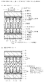
図15は、MVAモードにおいて用いられる配向技術を示す部分断面図である。図15(a)は、電界が印加されていないときの液晶分子の配向状態を示し、図15(b)は、電界を作用させたときの液晶分子120の配向状態を示している。MVAモードでは、フォトレジスト技術を用いて画素の中央に小さな透明の突起物(リブ)130を設けている。このため、電界が印加されていないとき、1画素中の大部分の液晶分子120は基板面に対し垂直に配向しているが、突起物(リブ)130の近傍の、図中、点線で囲んで示した液晶分子131は、基板面に垂直な方向から左または右に少し傾いた方向に配向している。このようにしておくと、電界を作用させたときに、突起物(リブ)130に接して予め傾斜している液晶分子131を起点として、他の液晶分子120がドミノ倒し的に配向変化を起こしていく。この結果、1つの画素は、突起物(リブ)130を境として、液晶分子の傾斜方向が互いに逆方向である偶数個のドメインに自動的に分割される。図15には左右に2つのドメインが形成される例を示したが、通常、突起物(リブ)130を中心として左右、前後に分割され、4つのドメインが形成される。 FIG. 15 is a partial cross-sectional view showing an alignment technique used in the MVA mode. FIG. 15A shows the alignment state of the liquid crystal molecules when no electric field is applied, and FIG. 15B shows the alignment state of the liquid crystal molecules 120 when the electric field is applied. In the MVA mode, a small transparent protrusion (rib) 130 is provided in the center of the pixel using a photoresist technique. For this reason, when no electric field is applied, most of the liquid crystal molecules 120 in one pixel are aligned perpendicularly to the substrate surface, but are surrounded by dotted lines in the figure near the protrusions (ribs) 130. The liquid crystal molecules 131 indicated by are oriented in a direction slightly tilted to the left or right from the direction perpendicular to the substrate surface. In this way, when an electric field is applied, the other liquid crystal molecules 120 undergo a domino-inclined orientation change starting from the liquid crystal molecules 131 that are inclined in advance in contact with the protrusions (ribs) 130. To go. As a result, one pixel is automatically divided into an even number of domains in which the tilt directions of the liquid crystal molecules are opposite to each other with the protrusion (rib) 130 as a boundary. Although FIG. 15 shows an example in which two domains are formed on the left and right, it is usually divided into left and right and front and rear with a protrusion (rib) 130 as the center to form four domains.
図15(b)に示すように、MVAモードでは、斜め方向から液晶画面を見た場合でも、1画素中の複数のドメインから、傾斜方向が互いに逆方向である液晶分子を通過した光が届くので、角度依存性が平均化され、視野角依存性が小さく抑えられる。 As shown in FIG. 15B, in the MVA mode, even when the liquid crystal screen is viewed from an oblique direction, light that has passed through liquid crystal molecules whose inclination directions are opposite to each other arrives from a plurality of domains in one pixel. Therefore, the angle dependency is averaged, and the viewing angle dependency is kept small.
図16は、PVAモードにおいて用いられる配向技術を示す部分断面図である。図16(a)は、電界を作用させ始めた直後の液晶分子の配向状態を示し、図16(b)は、電界を作用させた後、十分時間が経過して配向が完了したときの液晶分子120の配向状態を示している。PVAモードでは、透明電極140にスリット141を設け、一部の液晶分子に斜め方向の電界(フリンジ電界)が加わるようにして、液晶分子120が傾く方向を制御する。この場合、電界を作用させたとき、まず、図16(a)中に点線で囲んで示した、斜め方向の電界(フリンジ電界)を受けた液晶分子142が、電界方向に応じて左方向または右方向に傾き、次に、これらの液晶分子を起点として、他の液晶分子がドミノ倒し的に配向変化を起こしていく。この結果、図16(b)に示すように、1つの画素は、スリット140を境として、液晶分子の傾斜方向が互いに逆方向である偶数個のドメインに自動的に分割される。
FIG. 16 is a partial cross-sectional view showing an alignment technique used in the PVA mode. FIG. 16A shows the alignment state of the liquid crystal molecules immediately after the application of the electric field, and FIG. 16B shows the liquid crystal when the alignment is completed after a sufficient time has elapsed after the application of the electric field. The orientation state of the molecule 120 is shown. In the PVA mode, a slit 141 is provided in the
PVAモードでは、MVAモードと同様に、斜め方向から液晶画面を見た場合でも、1画素中の複数のドメインから、傾斜方向が互いに逆方向である液晶分子を通過した光が届くので、角度依存性が平均化され、視野角依存性が小さく抑えられる。 In the PVA mode, as in the MVA mode, even when the liquid crystal screen is viewed from an oblique direction, light that has passed through liquid crystal molecules whose tilt directions are opposite to each other arrives from a plurality of domains in one pixel. And the viewing angle dependency is kept small.
MVAモードの液晶表示素子では、電界が印加されていない遮光時に一部の液晶分子131が基板面に対し垂直に配向していないので、液晶層に光異方性が生じ、遮光時の光透過率が、偏光板106aと106bの直交性によって決まる最小値よりも少し大きくなる。このため、図14に示したVAモードの液晶表示素子と比べると、コントラストが少し低下する可能性がある。一方、PVAモードの液晶表示素子では、遮光時にすべての液晶分子120が基板面に対し垂直に配向しているので、真の暗黒に近い黒を実現することができ、高いコントラストが得られる。 In the MVA mode liquid crystal display element, since some liquid crystal molecules 131 are not aligned perpendicular to the substrate surface when light is not applied with an electric field, light anisotropy occurs in the liquid crystal layer, and light is transmitted when light is blocked. The rate is slightly larger than the minimum value determined by the orthogonality between the polarizing plates 106a and 106b. For this reason, there is a possibility that the contrast is slightly lowered as compared with the VA mode liquid crystal display element shown in FIG. On the other hand, in the liquid crystal display element of the PVA mode, since all the liquid crystal molecules 120 are aligned perpendicularly to the substrate surface at the time of light shielding, black close to true darkness can be realized and high contrast can be obtained.
上述したように、MVAモ−ドやPVAモ−ドを含めてVAモードにおいて、配向膜104は必須のものではない。但し、液晶分子120の垂直配向を補助するものとして垂直配向膜が形成されることがある。前述した水平配向膜では、液晶分子が配向膜にほぼ平行に並ぶように、液晶分子を配向させるのに対し、垂直配向膜では、液晶分子が配向膜に垂直に並ぶように、液晶分子を配向させる。従って、垂直配向膜には、水平配向膜とは全く異なる表面物性や表面構造が求められる。このため、垂直配向膜の材料として、例えば、垂直配向タイプのポリイミドやシランカップリング剤系垂直配向材料が用いられ、通常、ラビング処理は行われない。このように、ひとまとめに配向膜と呼ばれていても、水平配向膜と垂直配向膜とは、目的もその実現方法も全く異なり、別種の膜であると考える方がよい。 As described above, the alignment film 104 is not essential in the VA mode including the MVA mode and the PVA mode. However, a vertical alignment film may be formed to assist the vertical alignment of the liquid crystal molecules 120. In the horizontal alignment film described above, the liquid crystal molecules are aligned so that the liquid crystal molecules are aligned almost parallel to the alignment film, whereas in the vertical alignment film, the liquid crystal molecules are aligned so that the liquid crystal molecules are aligned vertically to the alignment film. Let Therefore, the vertical alignment film is required to have surface properties and a surface structure that are completely different from those of the horizontal alignment film. For this reason, as a material of the vertical alignment film, for example, a vertical alignment type polyimide or a silane coupling agent-based vertical alignment material is used, and the rubbing process is not usually performed. As described above, even if they are collectively called an alignment film, it is better to consider that the horizontal alignment film and the vertical alignment film are different types of films because they have completely different purposes and implementation methods.
さて、図14に示した単純なVAモードでは、電界を作用させたときに液晶分子120が傾く方向を規制する突起物(リブ)130やスリット140がない。この場合、液晶分子120が基板面の法線方向からどの方向に傾いても等価であるので、電界を作用させたときに液晶分子120が傾く方向が不定になりやすい。これを防止するには、水平配向膜によってプレチルトを発現させたように、電界が印加されていないときに、液晶分子120の長軸方向が基板面の法線方向から所定の方向にわずかに傾くように、垂直配向膜によって規制しておくことが望ましい。
In the simple VA mode shown in FIG. 14, there are no protrusions (ribs) 130 and
MVAモ−ドやPVAモ−ドでは、上述したように、電界を作用させたときに液晶分子120が傾く方向が不定になることはない。しかし、MVAモ−ドでは、突起物(リブ)130近傍の、予め傾斜している液晶分子131を起点として、他の液晶分子がドミノ倒し的に配向変化を起こしていくため、すべての液晶分子が一斉に配向変化を起こす場合に比べて、応答速度が遅くなる。また、PVAモ−ドでも、初めに斜め方向の電界(フリンジ電界)で傾斜した液晶分子142を起点として、他の液晶分子がドミノ倒し的に配向変化を起こしていくため、すべての液晶分子が一斉に配向変化を起こす場合に比べて、応答速度が遅くなる。PVAモ−ドではさらに、液晶層101に垂直にしか電界を作用させられない領域に、表示に寄与しない領域が生じる不都合もある。従って、これらの動作モードにおいても、電界が印加されていないときに、液晶分子120の長軸方向が基板面の法線方向から所定の方向にわずかに傾くように、垂直配向膜によって規制しておくことが望ましい。
In the MVA mode and the PVA mode, as described above, the direction in which the liquid crystal molecules 120 are tilted when an electric field is applied is not indefinite. However, in the MVA mode, since the liquid crystal molecules 131 that are inclined in advance in the vicinity of the protrusions (ribs) 130 are the starting points, other liquid crystal molecules undergo a domino-inclined orientation change, so that all the liquid crystal molecules Compared with the case where the alignment changes all at once, the response speed becomes slower. Also, in the PVA mode, since the liquid crystal molecules 142 that are initially tilted by an oblique electric field (fringe field) are the starting points, other liquid crystal molecules undergo a domino-inclined orientation change, so that all the liquid crystal molecules The response speed is slower than when the orientation changes occur all at once. Further, in the PVA mode, there is a disadvantage that a region that does not contribute to display is generated in a region in which an electric field can be applied only perpendicularly to the
電界が印加されていないときに、液晶分子120の配向方向を基板面の法線方向からわずかに傾ける方法の1つとして、垂直配向膜の表面をラビング処理によって加工する方法が考えられるが、この方法はむらを生じやすく、均一な傾きを実現することが困難であり、行われていない。 As a method of slightly tilting the alignment direction of the liquid crystal molecules 120 from the normal direction of the substrate surface when an electric field is not applied, a method of processing the surface of the vertical alignment film by rubbing treatment is considered. The method is prone to unevenness, it is difficult to achieve a uniform tilt and is not performed.
他の方法として、光配向性材料を用いる垂直配向膜の製造方法が提案されている。光配向性材料は、斜め方向からの光の照射を受けると異方的な液晶配向能が発生する材料である。この方法では、光配向性を有する垂直配向材料を用いて垂直配向膜を形成した後、垂直配向膜に斜め方向から光を照射することによって異方的な液晶配向能を発現させる。例えば、後述の特許文献3には、垂直配向ポリイミド膜を形成し、照射方向を変えて光を2度照射する方法が提案され、作製した垂直配向の液晶セルのプレチルト角が88゜(基板面の法線方向からの傾きが2°)であった例が報告されている。
As another method, a method for manufacturing a vertical alignment film using a photo-alignment material has been proposed. The photo-alignment material is a material that generates anisotropic liquid crystal alignment ability when irradiated with light from an oblique direction. In this method, after forming a vertical alignment film using a vertical alignment material having photo-alignment properties, anisotropic alignment of liquid crystals is exhibited by irradiating the vertical alignment film with light from an oblique direction. For example,
垂直配向膜を加工する方法とは異なるが、後述の特許文献4には、MVAモードによる液晶表示装置において、一定方向に配向した高分子状硬化物を液晶層中に形成することによって、電界が印加されていないときの液晶分子の配向方向を、基板面の法線方向からわずかに傾かせた液晶表示装置が提案されている。高分子状硬化物は、光硬化性の液晶性モノマーを少量液晶層に混入させておき、液晶セルを組み立てた後、液晶層に電圧を印加して液晶分子および液晶性モノマーを配向させた状態で、液晶層に紫外光を照射することによって形成する。この高分子状硬化物は、液晶分子の配向を効果的に制御できるように、液晶性骨格を備えていることが望ましい。
Although different from the method of processing the vertical alignment film, in
上述したように、基板面の法線方向からわずかに傾いた方向に液晶分子を配向させる方法としては、ラビング処理を除けば、光配向性材料からなる垂直配向膜を用いる構成が特許文献2などで提案され、また、液晶分子を配向させる高分子状硬化物を液晶層中に設ける構成が特許文献3で提案されている。
As described above, as a method of aligning liquid crystal molecules in a direction slightly tilted from the normal direction of the substrate surface, a configuration using a vertical alignment film made of a photo-alignment material except for rubbing treatment is disclosed in
しかし、光配向性材料を用いる構成は、長時間駆動や熱的な信頼性といった点に関して不十分である。また、特許文献3のように液晶層中に配向用構造物を設ける構成は、液晶層中にイオン性の不純物が混入することによって電圧保持率が低下したり、配向用構造物によって液晶表示素子の動作特性や光学特性が損なわれたりすることなどが懸念される。
However, the configuration using the photo-alignment material is insufficient in terms of long-time driving and thermal reliability. In addition, in the configuration in which the alignment structure is provided in the liquid crystal layer as in
特許文献1には、配向した液晶性材料からなる配向膜の製造方法が提案されている。しかし、これらは、例えばプレチルト角が10°程度の水平配向膜の製造方法であり、垂直配向膜の製造方法ではない。例えば、特許文献1で提案されている水平配向膜の構成材料や製造方法はそのままにして、単に印加する磁場や電場の方向を変更するだけで、90°近いプレチルト角を有する垂直配向膜を精度よく形成することは不可能である。また、磁場を用いる製造方法は、設備が大型化してコスト高になりやすい。さらに、均一な磁場を生成できる面積が限定されることから、比較的小さな画面の液晶表示素子の製造に限定される。
本発明は、このような状況に鑑みてなされたものであって、その目的は、表示用液晶分子を基板面に垂直な方向から所定の方向へわずかに傾いた方向に配向させる垂直配向膜として好適な、信頼性の高い配向膜及びその製造方法、その配向膜を備えた配向基板及びその製造方法、並びに液晶表示素子を提供することにある。 The present invention has been made in view of such a situation, and an object thereof is a vertical alignment film that aligns liquid crystal molecules for display in a direction slightly inclined from a direction perpendicular to the substrate surface to a predetermined direction. An object of the present invention is to provide a preferred alignment film having high reliability and a method for manufacturing the alignment film, an alignment substrate including the alignment film, a method for manufacturing the alignment film, and a liquid crystal display element.
即ち、本発明は、表示用液晶分子からなる液晶層と、この層を挟んで対向して配置された基板とを有する液晶表示素子において、前記基板の少なくとも一方に前記液晶層に接するように設けられ、前記表示用液晶分子の配向方向を、前記基板面に垂直な方向から所定の方向へわずかに傾いた方向に制御する配向膜において、
液晶性骨格を有し、異種物質との界面においてディレクタ(配向ベクトル)を界面に 垂直に向けて配向する性質と、重合する性質とを有する重合性液晶分子からなる層から 形成された配向層が、水平配向膜材料からなる下地層に積層された複層膜であり、
前記配向層に接する前記下地層の表面は、前記重合性液晶分子の前記ディレクタを、 前記基板面に平行な方向から所定の方向へわずかに傾かせて配向させる性質を有し、
前記の重合性液晶分子からなる層においては、前記ディレクタの配向方向が、前記下 地層との界面では、前記した前記基板面に平行な方向から所定の方向へわずかに傾いた 方向に制御され、この界面から層厚方向へ遠ざかるほど、前記基板面に垂直な方向へ徐 々に近づいていくハイブリッド配向構造を有する液晶状態が形成されており、
この状態で前記重合性液晶分子の少なくとも一部が重合し、前記の重合性液晶分子か らなる層が、未反応の重合性液晶分子と重合性液晶分子重合体との複合体からなる硬化 層に変化することによって、前記配向層が形成され、
前記の重合性液晶分子からなる層において形成されていた前記ハイブリッド配向構造 が前記配向層において固定され、前記配向層の表面における前記複合体のディレクタの 配向方向が、前記基板面に垂直な方向から所定の方向へわずかに傾いた方向に固定され ている
ことを特徴とする、配向膜に係わるものである。
That is, the present invention provides a liquid crystal display element having a liquid crystal layer composed of liquid crystal molecules for display and a substrate disposed so as to face the layer, and is provided on at least one of the substrates so as to be in contact with the liquid crystal layer. In an alignment film that controls the alignment direction of the display liquid crystal molecules in a direction slightly inclined from a direction perpendicular to the substrate surface to a predetermined direction,
An alignment layer formed of a layer composed of polymerizable liquid crystal molecules having a liquid crystalline skeleton and having a property of aligning a director (orientation vector) perpendicularly to the interface and a property of polymerizing at the interface with a different substance. A multi-layer film laminated on a base layer made of a horizontal alignment film material,
The surface of the underlayer in contact with the alignment layer has a property of aligning the director of the polymerizable liquid crystal molecules slightly tilted from a direction parallel to the substrate surface to a predetermined direction,
In the layer composed of the polymerizable liquid crystal molecules, the orientation direction of the director is controlled to a direction slightly inclined from a direction parallel to the substrate surface to a predetermined direction at the interface with the base layer, The further away from the interface in the layer thickness direction, the liquid crystal state having a hybrid alignment structure that gradually approaches the direction perpendicular to the substrate surface is formed,
In this state, at least a part of the polymerizable liquid crystal molecules is polymerized, and the layer made of the polymerizable liquid crystal molecules is a cured layer made of a composite of unreacted polymerizable liquid crystal molecules and polymerizable liquid crystal molecule polymer. The alignment layer is formed by changing to
The hybrid alignment structure formed in the layer composed of the polymerizable liquid crystal molecules is fixed in the alignment layer, and the alignment direction of the director of the composite on the surface of the alignment layer is from the direction perpendicular to the substrate surface. The present invention relates to an alignment film characterized by being fixed in a direction slightly tilted in a predetermined direction.
なお、液晶分子のディレクタ(配向ベクトル)の配向方向とは、液晶分子の液晶性骨格の長軸の平均的な配向方向である。また、前記重合性液晶分子の重合は、前記複合体が硬化し、前記複合体中の前記液晶性骨格の配向方向が確実に固定される程度まで起こればよい。上記の「前記重合性液晶分子の少なくとも一部が重合する」とは、この条件を満たしていれば、前記複合体中に未反応の重合性液晶分子が多少残存していてもよいという意味である。未反応の重合性液晶分子を完全になくすことは必要ではないし、実際上、それはほとんど不可能である。また、前記重合性液晶分子は、重合性モノマーであることが多いが、そのダイマーなどのオリゴマーであってもよい。 The alignment direction of the director (alignment vector) of the liquid crystal molecules is an average alignment direction of the major axes of the liquid crystalline skeleton of the liquid crystal molecules. Further, the polymerization of the polymerizable liquid crystal molecules may be performed to such an extent that the composite is cured and the alignment direction of the liquid crystalline skeleton in the composite is reliably fixed. The phrase “at least a part of the polymerizable liquid crystal molecules is polymerized” means that some unreacted polymerizable liquid crystal molecules may remain in the composite as long as this condition is satisfied. is there. It is not necessary to completely eliminate unreacted polymerizable liquid crystal molecules, and in practice it is almost impossible. The polymerizable liquid crystal molecules are often polymerizable monomers, but may be oligomers such as dimers thereof.
本発明は、また、表示用液晶分子からなる液晶層と、この層を挟んで対向して配置された基板とを有する液晶表示素子において、前記基板の少なくとも一方に前記液晶層に接するように設けられ、前記表示用液晶分子の配向方向を、前記基板面に垂直な方向から所定の方向へわずかに傾いた方向に制御する配向膜の形成方法において、
水平配向膜材料からなる下地層を前記基板に形成し、この下地層の表面に、重合性液 晶分子のディレクタ(配向ベクトル)を前記基板面に平行な方向から所定の方向へわず かに傾かせて配向させる配向性を付与する工程と、
液晶性骨格を有し、異種物質との界面において前記ディレクタを界面に垂直に向けて 配向する性質と、重合する性質とを有する前記重合性液晶分子からなる層を、前記下地 層に積層して、液晶状態にて形成する工程と、
前記重合性液晶分子の少なくとも一部を重合させ、前記の重合性液晶分子からなる層 を、未反応の重合性液晶分子と重合性液晶分子重合体との複合体からなる硬化層に変化 させることによって、配向層を形成する工程と
を有し、
前記の重合性液晶分子からなる層において形成されていた前記液晶状態が有するハイ ブリッド配向構造、すなわち、前記ディレクタの配向方向が、前記下地層との界面では 、前記した前記基板面に平行な方向から所定の方向へわずかに傾いた方向に制御され、 この界面から層厚方向へ遠ざかるほど、前記基板面に垂直な方向へ徐々に近づいていき 、表面では前記基板面に垂直な方向から所定の方向へわずかに傾いた方向である配向構 造を、前記配向層において固定する
ことを特徴とする、配向膜の形成方法に係わるものである。
The present invention also provides a liquid crystal display element having a liquid crystal layer composed of liquid crystal molecules for display and a substrate disposed so as to face the layer, and is provided on at least one of the substrates so as to be in contact with the liquid crystal layer. In the method of forming an alignment film, the alignment direction of the liquid crystal molecules for display is controlled in a direction slightly inclined from a direction perpendicular to the substrate surface to a predetermined direction.
An underlayer made of a horizontal alignment film material is formed on the substrate, and a director (orientation vector) of polymerizable liquid crystal molecules is slightly formed on the surface of the underlayer from a direction parallel to the substrate surface to a predetermined direction. Providing an orientation for tilting and orientation;
A layer made of the polymerizable liquid crystal molecules having a liquid crystalline skeleton and having the property of orienting the director perpendicularly to the interface at the interface with the different substance and the property of polymerizing are laminated on the base layer. Forming in a liquid crystal state;
Polymerizing at least a part of the polymerizable liquid crystal molecules, and changing the layer composed of the polymerizable liquid crystal molecules into a cured layer composed of a complex of an unreacted polymerizable liquid crystal molecule and a polymerizable liquid crystal molecule polymer; And a step of forming an alignment layer,
The hybrid alignment structure of the liquid crystal state formed in the layer composed of the polymerizable liquid crystal molecules, that is, the alignment direction of the director is a direction parallel to the substrate surface at the interface with the base layer. From the interface to the layer thickness direction and gradually approach the direction perpendicular to the substrate surface, and on the surface from the direction perpendicular to the substrate surface to a predetermined direction. The present invention relates to a method for forming an alignment film, characterized in that an alignment structure having a slightly inclined direction is fixed in the alignment layer.
また、液晶表示素子の、表示用液晶分子からなる液晶層に接して配置される基板において、
前記配向膜が、前記液晶層に接する面側に設けられている
ことを特徴とする、配向基板に係わり、また、液晶表示素子の、表示用液晶分子からなる液晶層に接して配置される基板の製造方法において、
前記配向膜の形成方法によって、前記液晶層に接する面側に配向膜を形成する工程を 含む
ことを特徴とする、配向基板の製造方法に係わるものである。
Further, in the substrate disposed in contact with the liquid crystal layer composed of the display liquid crystal molecules of the liquid crystal display element,
The alignment film is provided on a surface side in contact with the liquid crystal layer, and relates to an alignment substrate, and a substrate disposed in contact with a liquid crystal layer composed of display liquid crystal molecules of a liquid crystal display element In the manufacturing method of
The present invention relates to a method for manufacturing an alignment substrate, which includes a step of forming an alignment film on a surface in contact with the liquid crystal layer by the alignment film forming method.
また、表示用液晶分子からなる液晶層と、この層を挟んで対向して配置された基板とを有する液晶表示素子において、
前記配向膜が、前記基板の少なくとも一方に、前記液晶層に接するように設けられ、
電界が印加されていないときの、前記表示用液晶分子の配向方向が、前記基板面に垂 直な方向から所定の方向へわずかに傾いた方向に制御されている
ことを特徴とする、液晶表示素子に係わるものである。
In addition, in a liquid crystal display element having a liquid crystal layer composed of display liquid crystal molecules and a substrate disposed opposite to the layer,
The alignment film is provided on at least one of the substrates so as to be in contact with the liquid crystal layer;
The liquid crystal display, wherein an orientation direction of the liquid crystal molecules for display when an electric field is not applied is controlled in a direction slightly inclined from a direction perpendicular to the substrate surface to a predetermined direction It relates to the element.
本発明の配向膜は、表示用液晶分子からなる液晶層と、この層を挟んで対向して配置された基板とを有する液晶表示素子において、前記基板の少なくとも一方に前記液晶層に接するように設けられ、前記表示用液晶分子の配向方向を、前記基板面に垂直な方向から所定の方向へわずかに傾いた方向に制御する配向膜であって、水平配向膜材料からなる下地層に、重合する性質を有する重合性液晶分子からなる層が積層された後、前記重合性液晶分子の少なくとも一部が重合し、前記の重合性液晶分子からなる層が、未反応の重合性液晶分子と重合性液晶分子重合体との複合体からなる配向層に硬化することによって形成された複層膜である。 The alignment film of the present invention is a liquid crystal display device having a liquid crystal layer composed of display liquid crystal molecules and a substrate disposed so as to face the layer, so that at least one of the substrates is in contact with the liquid crystal layer. An alignment film that is provided and controls the alignment direction of the liquid crystal molecules for display from a direction perpendicular to the substrate surface to a direction slightly inclined from a direction perpendicular to the substrate surface. After the layer composed of polymerizable liquid crystal molecules having the property to be laminated, at least a part of the polymerizable liquid crystal molecules is polymerized, and the layer composed of the polymerizable liquid crystal molecules is polymerized with unreacted polymerizable liquid crystal molecules. It is the multilayer film formed by hardening to the orientation layer which consists of a composite_body | complex with a liquid crystalline molecular polymer.
この際、前記重合性液晶分子は、液晶性骨格を有し、異種物質との界面においてディレクタ(配向ベクトル)を界面に垂直に向けて配向する性質を有し、一方、前記下地層の、前記の重合性液晶分子からなる層に接する表面は、前記重合性液晶分子の前記ディレクタを、前記基板面に平行な方向から所定の方向へわずかに傾かせて配向させる性質を有している。この結果、前記重合性液晶分子が前記液晶状態に保たれると、前記の重合性液晶分子からなる層において、前記ディレクタの配向方向が、前記下地層との界面では、前記した前記基板面に平行な方向から所定の方向へわずかに傾いた方向に制御され、この界面から層厚方向へ遠ざかるほど、前記基板面に垂直な方向へ徐々に近づいていくハイブリッド配向構造が形成される。 At this time, the polymerizable liquid crystal molecules have a liquid crystalline skeleton, and have a property of aligning a director (orientation vector) perpendicularly to the interface at the interface with the foreign material, The surface in contact with the layer made of polymerizable liquid crystal molecules has the property of aligning the director of the polymerizable liquid crystal molecules slightly tilted from a direction parallel to the substrate surface to a predetermined direction. As a result, when the polymerizable liquid crystal molecules are maintained in the liquid crystal state, in the layer composed of the polymerizable liquid crystal molecules, the orientation direction of the director is on the substrate surface described above at the interface with the base layer. A hybrid alignment structure is formed which is controlled in a direction slightly inclined from a parallel direction to a predetermined direction and gradually approaches a direction perpendicular to the substrate surface as the distance from the interface in the layer thickness direction increases.
前記配向層では、前記重合によって、前記の重合性液晶分子からなる層において形成されていた前記ハイブリッド配向構造が、前記複合体のハイブリッド配向構造として固定されている。従って、前記配向層の表面における前記複合体のディレクタの配向方向は、前記の重合性液晶分子からなる層の表面における前記ディレクタの配向方向と概ね一致すると考えられる。本発明の配向膜では、表面における前記ディレクタの配向方向、並びに前記複合体のディレクタの配向方向が、前記基板面に垂直な方向から所定の方向へわずかに傾いた方向に定められている。 In the alignment layer, the hybrid alignment structure formed in the layer composed of the polymerizable liquid crystal molecules is fixed as a hybrid alignment structure of the composite by the polymerization. Therefore, it is considered that the alignment direction of the director of the composite on the surface of the alignment layer substantially coincides with the alignment direction of the director on the surface of the layer made of the polymerizable liquid crystal molecules. In the alignment film of the present invention, the alignment direction of the director on the surface and the alignment direction of the director of the composite are determined to be slightly inclined from a direction perpendicular to the substrate surface to a predetermined direction.
このようであると、前記複合体は、液晶分子間の相互作用によって、電界が印加されていないときの、前記表示用液晶分子の配向方向を、前記基板面に垂直な方向から所定の方向へわずかに傾いた方向に制御することができる。この配向膜は、後述するように、例えばVAモードで動作する液晶表示素子において垂直配向膜として用いることができ、液晶表示素子に良好な動作特性や光学特性を付与することができる。垂直配向膜として用いる場合、前記配向層の表面における前記複合体のディレクタの配向方向の傾きが小さすぎると、垂直配向膜としての機能が得られず、大きすぎると、面内リタデーションが大きくなり、正面コントラストが低下する傾向がある。前記「わずかに傾いた(方向)」とは、垂直配向膜として好適な特性が得られる傾きを意味する。 In such a case, the composite has an alignment direction of the liquid crystal molecules for display when an electric field is not applied due to an interaction between the liquid crystal molecules, from a direction perpendicular to the substrate surface to a predetermined direction. It can be controlled in a slightly tilted direction. As will be described later, this alignment film can be used as a vertical alignment film in, for example, a liquid crystal display element operating in the VA mode, and can impart good operating characteristics and optical characteristics to the liquid crystal display element. When used as a vertical alignment film, if the inclination of the alignment direction of the director of the composite on the surface of the alignment layer is too small, the function as the vertical alignment film cannot be obtained, and if it is too large, the in-plane retardation increases, The front contrast tends to decrease. The term “slightly tilted (direction)” means a tilt that can provide characteristics suitable as a vertical alignment film.
前記ハイブリッド配向構造は、前記下地層が前記重合性液晶分子の配向を規制する力、前記重合性液晶分子の弾性定数、前記の重合性液晶分子からなる層の厚さ、及び、表面(すなわち、形成時における他方の異種物質相である雰囲気ガス相との界面)が前記重合性液晶分子の配向を規制する力によって決まる(以下、雰囲気ガス相を単に気相と略記する。雰囲気ガスは、例えば、窒素ガスや空気である。)。前記の重合性液晶分子からなる層のバルクにおける前記ディレクタの配向は、いわゆる連続弾性体理論で理解され、前述したように、前記下地層との界面から気相との界面まで、層厚方向において連続的に変化する。この際、前記下地層を水平配向膜にしておくと、一般に水平配向膜の配向規制力の方が気相との界面の配向規制力よりも強いため、気相との界面における前記ディレクタの配向方向を前記基板面に垂直な方向から所定の方向へ傾いた方向に制御できると考えられる。従って、前記下地層の配向規制力が強く、気相との界面の配向規制力が弱いほど、また、前記の重合性液晶分子からなる層の厚さが薄いほど、配向方向の傾きは大きくなる。 In the hybrid alignment structure, the underlying layer regulates the alignment of the polymerizable liquid crystal molecules, the elastic constant of the polymerizable liquid crystal molecules, the thickness of the layer composed of the polymerizable liquid crystal molecules, and the surface (that is, The interface with the atmosphere gas phase, which is the other heterogeneous material phase at the time of formation, is determined by the force that regulates the orientation of the polymerizable liquid crystal molecules (hereinafter, the atmosphere gas phase is simply abbreviated as the gas phase. Nitrogen gas or air.) The director orientation in the bulk of the layer composed of the polymerizable liquid crystal molecules is understood by the so-called continuous elastic body theory, and as described above, in the layer thickness direction from the interface with the underlayer to the interface with the gas phase. It changes continuously. At this time, if the underlying layer is a horizontal alignment film, the alignment regulating force of the horizontal alignment film is generally stronger than the alignment regulating force of the interface with the gas phase. It is considered that the direction can be controlled in a direction inclined from a direction perpendicular to the substrate surface to a predetermined direction. Accordingly, the orientation regulating force of the underlayer is stronger, the orientation regulating force at the interface with the gas phase is weaker, and the thinner the layer composed of the polymerizable liquid crystal molecules is, the larger the inclination of the orientation direction becomes. .
本発明の配向膜では、適切に条件を選択して、気相との界面における前記ディレクタの配向方向を前記基板面に垂直な方向から所定の方向へわずかに傾いた方向に制御する。例えば、前記下地層の配向規制力を弱くするには、前記下地層のラビング強度を小さくするか、光配向処理の条件(紫外線の偏光度や照度)を調節する。また、前記の重合性液晶分子からなる層の厚さは、この層を塗布法で形成する際に用いる前記重合性液晶分子の溶液の濃度を調節したり、塗布条件を調節したりすることなどで制御することが可能である。前記複合体のディレクタの配向方向を正確に測定するのは容易ではないが、前記ハイブリッド配向構造が固定された前記配向層において、リタデーションのあおり角(入射角)依存性を測定し、別途測定しておいた前記配向層の厚さ、前記重合性液晶分子の弾性定数、および前記下地層の配向規制力(アンカリング力)を用いて算出することができる。 In the alignment film of the present invention, the conditions are appropriately selected and the alignment direction of the director at the interface with the gas phase is controlled to be slightly inclined from a direction perpendicular to the substrate surface to a predetermined direction. For example, in order to weaken the orientation regulating force of the underlayer, the rubbing strength of the underlayer is reduced or the conditions of the photo-alignment treatment (the degree of polarization of ultraviolet rays and the illuminance) are adjusted. The thickness of the layer composed of the polymerizable liquid crystal molecules may be adjusted by adjusting the concentration of the solution of the polymerizable liquid crystal molecules used when forming this layer by a coating method, or by adjusting the coating conditions. It is possible to control with. Although it is not easy to accurately measure the orientation direction of the director of the composite, the dependency of retardation on the tilt angle (incident angle) is measured in the alignment layer to which the hybrid alignment structure is fixed. It can be calculated using the thickness of the alignment layer, the elastic constant of the polymerizable liquid crystal molecules, and the alignment regulating force (anchoring force) of the underlayer.
本発明の配向膜の形成方法は、
水平配向膜材料からなる下地層を前記基板に形成し、この下地層の表面に、重合性液 晶分子のディレクタ(配向ベクトル)を前記基板面に平行な方向から所定の方向へわず かに傾かせて配向させる配向性を付与する工程と、
液晶性骨格を有し、異種物質との界面において前記ディレクタを界面に垂直に向けて 配向する性質と、重合する性質とを有する前記重合性液晶分子からなる層を、前記下地 層に積層して、液晶状態にて形成する工程と、
を有する。この結果、前記の重合性液晶分子からなる層において、前記ディレクタの配向方向が、前記下地層との界面では、前記した前記基板面に平行な方向から所定の方向へわずかに傾いた方向に制御され、この界面から層厚方向へ遠ざかるほど、前記基板面に垂直な方向へ徐々に近づいていき、表面では前記基板面に垂直な方向から所定の方向へわずかに傾いた方向であるハイブリッド配向構造を有する前記液晶状態を形成することができる。
The method for forming the alignment film of the present invention includes:
An underlayer made of a horizontal alignment film material is formed on the substrate, and a director (orientation vector) of polymerizable liquid crystal molecules is slightly formed on the surface of the underlayer from a direction parallel to the substrate surface to a predetermined direction. Providing an orientation for tilting and orientation;
A layer made of the polymerizable liquid crystal molecules having a liquid crystalline skeleton and having the property of orienting the director perpendicularly to the interface at the interface with the different substance and the property of polymerizing are laminated on the base layer. Forming in a liquid crystal state;
Have As a result, in the layer composed of the polymerizable liquid crystal molecules, the orientation direction of the director is controlled to be slightly inclined from a direction parallel to the substrate surface to a predetermined direction at the interface with the base layer. The hybrid alignment structure is such that the distance from the interface in the layer thickness direction gradually approaches the direction perpendicular to the substrate surface and the surface is slightly inclined from the direction perpendicular to the substrate surface to a predetermined direction. The liquid crystal state having can be formed.
また、重合する性質を有する前記重合性液晶分子を用いるので、
前記重合性液晶分子の少なくとも一部を重合させ、前記の重合性液晶分子からなる層 を、未反応の重合性液晶分子と重合性液晶分子重合体との複合体からなる硬化層に変化 させることによって、配向層を形成する工程
によって、前記の重合性液晶分子からなる層における前記ハイブリッド配向構造を、前記配向層における前記複合体のハイブリッド配向構造として固定することができる。
Moreover, since the polymerizable liquid crystal molecules having the property of polymerizing are used,
Polymerizing at least a part of the polymerizable liquid crystal molecules, and changing the layer composed of the polymerizable liquid crystal molecules into a cured layer composed of a complex of an unreacted polymerizable liquid crystal molecule and a polymerizable liquid crystal molecule polymer; By the step of forming the alignment layer, the hybrid alignment structure in the layer composed of the polymerizable liquid crystal molecules can be fixed as the hybrid alignment structure of the complex in the alignment layer.
以上の結果、前記配向層の表面における前記複合体のディレクタの配向方向が、前記基板面に垂直な方向から所定の方向へわずかに傾いた方向に固定されている、本発明の配向膜を、容易、且つ確実に形成することができる。 As a result of the above, the alignment direction of the director of the composite on the surface of the alignment layer is fixed in a direction slightly inclined from a direction perpendicular to the substrate surface to a predetermined direction. It can be formed easily and reliably.
また、本発明の配向基板は、表示用液晶分子からなる液晶層に接して配置される、液晶表示素子の基板であって、本発明の配向膜を前記液晶層に接する面側に備えているので、本発明の配向膜の機能を発現させ、電界が印加されていないときに、前記表示用液晶分子の配向方向を、前記基板面に垂直な方向から所定の方向へわずかに傾いた方向に制御する配向基板として機能する。 The alignment substrate of the present invention is a substrate of a liquid crystal display element that is disposed in contact with a liquid crystal layer made of display liquid crystal molecules, and includes the alignment film of the present invention on the side in contact with the liquid crystal layer. Therefore, the function of the alignment film of the present invention is expressed, and when no electric field is applied, the alignment direction of the display liquid crystal molecules is slightly inclined from a direction perpendicular to the substrate surface to a predetermined direction. It functions as an alignment substrate to be controlled.
また、本発明の配向基板の製造方法は、表示用液晶分子からなる液晶層に接して配置される、液晶表示素子の基板の製造方法であって、本発明の配向膜の形成方法によって、前記液晶層に接する面側に配向膜を形成する工程を含むので、本発明の配向膜を備えた配向基板を確実に製造することができる。 A method for producing an alignment substrate of the present invention is a method for producing a substrate for a liquid crystal display element, which is disposed in contact with a liquid crystal layer comprising display liquid crystal molecules, and the method for forming an alignment film according to the present invention includes: Since the step of forming the alignment film on the surface side in contact with the liquid crystal layer is included, the alignment substrate provided with the alignment film of the present invention can be reliably manufactured.
また、本発明の液晶表示素子は、表示用液晶分子からなる液晶層と、この層を挟んで対向して配置された基板とを有する液晶表示素子であって、
本発明の前記配向膜が、前記基板の少なくとも一方に前記液晶層に接するように設け られ、
電界が印加されていないときの、前記表示用液晶分子の配向方向が、前記基板面に垂 直な方向から所定の方向へわずかに傾いた方向に制御されている
ことを特徴とする。この液晶表示素子を、例えば、VAモードで動作させると、電界を作用させたときに前記表示用液晶分子が傾く方向が不定にならず、リバースチルトを防止して、液晶表示素子としての良好な動作特性や光学特性を実現することができる。しかも、すべての前記表示用液晶分子が一斉に配向変化を起こすので、一部の液晶分子を起点として他の液晶分子がドミノ倒し的に配向変化を起こしていくMVAモ−ドやPVAモ−ドの液晶表示素子に比べ、より速い応答速度を実現することができる。
The liquid crystal display element of the present invention is a liquid crystal display element having a liquid crystal layer composed of liquid crystal molecules for display and a substrate disposed so as to face the layer.
The alignment film of the present invention is provided on at least one of the substrates so as to be in contact with the liquid crystal layer,
The alignment direction of the liquid crystal molecules for display when an electric field is not applied is controlled in a direction slightly inclined from a direction perpendicular to the substrate surface to a predetermined direction. When this liquid crystal display element is operated, for example, in the VA mode, the direction in which the liquid crystal molecules for display are tilted when an electric field is applied is not indefinite, and reverse tilt is prevented, making it an excellent liquid crystal display element. Operational characteristics and optical characteristics can be realized. In addition, since all the liquid crystal molecules for display cause an alignment change at the same time, the MVA mode or the PVA mode in which other liquid crystal molecules cause the alignment change in a domino manner starting from some liquid crystal molecules. Compared with the liquid crystal display element, faster response speed can be realized.
本発明の配向膜において、前記重合性液晶分子が、重合性官能基としてアクリロイルオキシ基、メタクリロイルオキシ基、ビニルオキシ基、及びエポキシ基からなる群から選ばれた少なくとも1つの官能基を有するのがよい。これらの官能基は、紫外線、赤外線又は電子線の照射、及び/又は、加熱によって重合させることができる。 In the alignment film of the present invention, the polymerizable liquid crystal molecule preferably has at least one functional group selected from the group consisting of an acryloyloxy group, a methacryloyloxy group, a vinyloxy group, and an epoxy group as a polymerizable functional group. . These functional groups can be polymerized by irradiation with ultraviolet rays, infrared rays or electron beams and / or heating.
また、前記下地層は、表面がラビング処理された有機高分子樹脂材料からなる膜、又は表面が光配向処理された光配向性材料からなる膜であるのがよい。表面がラビング処理されたポリイミドなどの有機高分子樹脂材料からなる膜は、従来から水平配向膜として用いられ、信頼性が高い。一方、光配向性材料からなる膜は、容易にパターニングできるなど、ラビング膜にはない特性をもつ水平配向膜として用いることができる。 The underlayer may be a film made of an organic polymer resin material whose surface is rubbed or a film made of a photo-alignment material whose surface is photo-aligned. A film made of an organic polymer resin material such as polyimide whose surface is rubbed has been conventionally used as a horizontal alignment film and has high reliability. On the other hand, a film made of a photo-alignment material can be used as a horizontal alignment film having characteristics not found in a rubbing film, such as easy patterning.
また、各画素中において、前記配向層が、前記複合体のディレクタの傾斜方向が異なる複数の領域にパターニングして形成されているのがよい。このようにすると、前記画素をマルチドメイン化して、前記液晶表示素子の視野角依存性を小さく抑えることができる。 Further, in each pixel, the alignment layer may be formed by patterning into a plurality of regions having different inclination directions of the director of the composite. In this way, the pixel can be multi-domained and the viewing angle dependency of the liquid crystal display element can be suppressed to a small value.
また、電界が印加されていないとき、前記表示用液晶分子を、前記基板面に垂直な方向から所定の方向へ0.1〜5度傾いた方向、望ましくは0.5〜2.5度傾いた方向、更に望ましくは0.8〜1.5度傾いた方向に配向させるのがよい。前記液晶表示素子の配向方向の傾きが小さすぎると、前述した、電界を作用させたときに前記表示用液晶分子が傾く方向を前記所定の方向に定める効果、および、すべての前記表示用液晶分子が一斉に配向変化を起こすことによって速い応答速度を実現する効果が得られない。一方、前記液晶表示素子の配向方向の傾きが大きすぎると、配向した前記液晶表示素子による光学異方性によって面内リタデーションが生じ、遮光時の光透過率が大きくなりすぎ、正面コントラストの低下が許容できない大きさになる。 Further, when no electric field is applied, the liquid crystal molecules for display are tilted by 0.1 to 5 degrees, preferably 0.5 to 2.5 degrees from a direction perpendicular to the substrate surface to a predetermined direction. The orientation is preferably in the direction inclined, more preferably in the direction inclined by 0.8 to 1.5 degrees. When the inclination of the alignment direction of the liquid crystal display element is too small, the above-described effect of setting the direction in which the display liquid crystal molecules are inclined when an electric field is applied to the predetermined direction, and all the display liquid crystal molecules However, the effect of realizing a fast response speed cannot be obtained by causing the orientation change all at once. On the other hand, if the tilt of the alignment direction of the liquid crystal display element is too large, in-plane retardation occurs due to the optical anisotropy by the aligned liquid crystal display element, the light transmittance at the time of light shielding becomes too large, and the front contrast decreases. It becomes an unacceptable size.
前記表示用液晶分子の配向方向は、例えば、クリスタルローテーション法で測定することができる。すなわち、前記配向膜を用いて作製された液晶素子のリタデーションのあおり角(入射角)依存性と、前記重合性液晶分子からなる前記配向膜のみのリタデーションのあおり角(入射角)依存性とを実測し、前記表示用液晶分子のリタデーションのあおり角(入射角)依存性を両者の差として求め、これから屈折率を考慮して算出することができる。 The alignment direction of the display liquid crystal molecules can be measured by, for example, a crystal rotation method. That is, the tilt angle (incident angle) dependence of the retardation of the liquid crystal device manufactured using the alignment film and the tilt angle (incident angle) dependence of the retardation of only the alignment film made of the polymerizable liquid crystal molecules are as follows. It is actually measured and the tilt angle (incident angle) dependency of the retardation of the liquid crystal molecules for display is obtained as a difference between the two, and can be calculated in consideration of the refractive index.
また、前記基板面の法線方向に関して、前記配向層の表面における前記複合体のディレクタの配向方向とは反対の方向へ、前記表示用液晶分子を傾斜させて配向させるのがよい。このような例は本発明の実施例において観察された。この場合、視野角の変化による階調変化を抑え、視野角依存性を改善する効果が得られる。 The display liquid crystal molecules may be tilted and aligned in a direction opposite to the alignment direction of the director of the composite on the surface of the alignment layer with respect to the normal direction of the substrate surface. Such an example was observed in the examples of the present invention. In this case, the effect of suppressing the change in gradation due to the change in viewing angle and improving the viewing angle dependency can be obtained.
前記複合体のディレクタの配向方向の傾きと、前記表示用液晶分子の配向方向の傾きとが反対向きになるメカニズムは、現在のところ、不明である。前記表示用液晶分子の配向を直接制御するのは、前記の重合性液晶分子からなる層において表面を占めていた重合性液晶分子から生じた複合体の液晶性骨格である。表面にある前記重合性液晶分子の液晶性骨格は気相に接しており、バルクと全く同じ弾性体理論で記述できるとは限らない。例えば、自由界面では表面エネルギーの関係から、前記重合性液晶分子中の特定の基が自由界面に向けて配列する可能性がある。また、前記の重合性液晶分子からなる層と気相との界面では密度が連続的に変化していると考えられるので、液晶相から等方相へ変化している状態とも考えることができる。このようなことが原因となって、表面の重合性液晶分子はバルクの重合性液晶分子とは異なる方向に配向しており、その結果、前記表示用液晶分子を、前記基板の法線方向に関して、バルクにおいて前記ディレクタが配向している方向と反対の方向に傾斜させて配向させるのかもしれない。 The mechanism by which the tilt in the alignment direction of the director of the composite and the tilt in the alignment direction of the liquid crystal molecules for display are opposite is unknown at present. Directly controlling the orientation of the liquid crystal molecules for display is the liquid crystalline skeleton of the composite formed from the polymerizable liquid crystal molecules occupying the surface in the layer composed of the polymerizable liquid crystal molecules. The liquid crystalline skeleton of the polymerizable liquid crystal molecules on the surface is in contact with the gas phase and cannot always be described by the same elastic body theory as the bulk. For example, a specific group in the polymerizable liquid crystal molecule may be arranged toward the free interface due to the relationship of surface energy at the free interface. Further, since the density is considered to change continuously at the interface between the layer composed of the polymerizable liquid crystal molecules and the gas phase, it can be considered that the liquid crystal phase is changed to the isotropic phase. Because of this, the surface polymerizable liquid crystal molecules are aligned in a different direction from the bulk polymerizable liquid crystal molecules, and as a result, the display liquid crystal molecules are aligned with respect to the normal direction of the substrate. In the bulk, the director may be tilted in the direction opposite to the direction in which the director is oriented.
また、前記重合性液晶分子を用いて前記ハイブリッド配向構造を有しない配向層を形成した場合、例えば、下地層に垂直配向膜を用いて前記重合性液晶分子の層を積層し、これを重合させて配向層を形成した場合、この配向層に接する前記表示用液晶分子の基板法線方向からの傾き角は0度であり、ディレクタの配向方向は基板法線方向であることも判明している。このことから、前記複合体のディレクタの配向方向とは反対向きに規制された、前記表示用液晶分子の配向方向は、前記の重合性液晶分子からなる層の前記ハイブリッド配向構造によって誘発された、表面(気相との界面)の異方的な構造に起因していると考えられる。 In addition, when an alignment layer having no hybrid alignment structure is formed using the polymerizable liquid crystal molecules, for example, a layer of the polymerizable liquid crystal molecules is stacked using a vertical alignment film as a base layer, and this is polymerized. When the alignment layer is formed, the tilt angle of the display liquid crystal molecules in contact with the alignment layer from the substrate normal direction is 0 degree, and the director alignment direction is also found to be the substrate normal direction. . From this, the alignment direction of the liquid crystal molecules for display, which is regulated in the direction opposite to the alignment direction of the director of the composite, is induced by the hybrid alignment structure of the layer composed of the polymerizable liquid crystal molecules. This is thought to be due to the anisotropic structure of the surface (interface with the gas phase).
本発明の垂直配向膜の形成方法において、前記の重合性液晶分子からなる層を形成する際、前記下地層に積層して前記重合性液晶分子からなる初期層を形成した後、一旦、前記初期層の温度を上昇させて、前記重合性液晶分子を等方相状態にし、その後、温度を徐々に低下させて、前記ハイブリッド配向構造を有する前記液晶状態の層を形成するのがよい。 In the method for forming a vertical alignment film of the present invention, when the layer made of the polymerizable liquid crystal molecules is formed, the initial layer made of the polymerizable liquid crystal molecules is formed after being laminated on the base layer, The temperature of the layer is raised to bring the polymerizable liquid crystal molecules into an isotropic phase, and then the temperature is gradually lowered to form the liquid crystal state layer having the hybrid alignment structure.
塗布法などで形成した前記重合性液晶分子からなる初期層は液晶状態にあるが、層が多数の小領域に分かれ、各小領域内では前記重合性液晶分子の配向方向が揃っているものの、小領域間では前記重合性液晶分子の配向方向がばらばらに異なっている状態にあり、ディスクリネーションなどの欠陥も存在している。上記のように、一旦等方相状態を経ることによって、これらの小領域を解消させ、欠陥を除去することができる。その後、前記重合性液晶分子が最適状態に配向する時間的余裕を与えながら、温度を徐々に低下させることによって、ほぼすべての重合性液晶分子に一様な前記ハイブリッド配向構造をとらせることができ、前記の重合性液晶分子からなる層を形成することができる。 Although the initial layer composed of the polymerizable liquid crystal molecules formed by a coating method or the like is in a liquid crystal state, the layer is divided into a large number of small regions, and the orientation direction of the polymerizable liquid crystal molecules is aligned in each small region, Between the small regions, the orientation directions of the polymerizable liquid crystal molecules are different from each other, and defects such as disclination are also present. As described above, once through the isotropic phase state, these small regions can be eliminated and defects can be removed. Thereafter, by gradually decreasing the temperature while giving the time to align the polymerizable liquid crystal molecules in the optimum state, almost all the polymerizable liquid crystal molecules can have the uniform hybrid alignment structure. A layer composed of the above polymerizable liquid crystal molecules can be formed.
また、紫外線、赤外線又は電子線の照射、及び/又は、加熱によって、前記重合性液晶分子を重合させるのがよい。前記重合性液晶分子を重合させる方法としては、これらの方法を挙げることができ、特に限定されるものではないが、適用できる前記重合性液晶分子の多様さや実施の容易さなどから、紫外線の照射が最も好ましい。この場合、前述したように、前記重合性液晶分子として、アクリロイルオキシ基、メタクリロイルオキシ基、ビニルエーテル基、及びエポキシ基からなる群から選ばれた少なくとも1つの官能基を重合性官能基として有する分子を用いるのがよい。 Further, the polymerizable liquid crystal molecules are preferably polymerized by irradiation with ultraviolet rays, infrared rays or electron beams and / or heating. Examples of the method for polymerizing the polymerizable liquid crystal molecules include these methods, and are not particularly limited. However, due to the diversity of the applicable polymerizable liquid crystal molecules and the ease of implementation, irradiation with ultraviolet rays is possible. Is most preferred. In this case, as described above, the polymerizable liquid crystal molecule is a molecule having as a polymerizable functional group at least one functional group selected from the group consisting of an acryloyloxy group, a methacryloyloxy group, a vinyl ether group, and an epoxy group. It is good to use.
また、前記下地層の表面に前記配向性を付与する工程を、有機高分子樹脂材料からなる膜のラビング処理、又は光配向性材料からなる膜の光配向処理によって行うのがよい。この理由は既述した通りである。 The step of imparting the orientation to the surface of the base layer may be performed by rubbing treatment of a film made of an organic polymer resin material or photo-alignment treatment of a film made of a photo-alignment material. The reason for this is as described above.
また、各画素中の前記下地層を、前記ディレクタを配向させる方向が異なる複数の領域にパターニングして形成することによって、各画素中の前記配向層を、前記ディレクタの傾斜方向が異なる複数の領域にパターニングして形成するのがよい。この理由も既述した通りである。 Further, the alignment layer in each pixel is formed by patterning the underlying layer in each pixel in a plurality of regions having different directions in which the director is aligned, thereby forming the alignment layer in each pixel in a plurality of regions having different inclination directions of the director. It is preferable to form by patterning. The reason for this is also as described above.
この際、各画素中の光配向性材料からなる下地層の一部の領域に、フォトマスクを用いて紫外線照射する光配向処理を、紫外線の照射方向を変えながら画素中の複数の領域ごとに行い、各画素中の前記下地層を、前記ディレクタを配向させる方向が異なる複数の領域にパターニングして形成するのがよい。 At this time, a photo-alignment process in which a photomask is used to irradiate a part of the base layer made of a photo-alignment material in each pixel with ultraviolet light is applied to each of the plurality of regions in the pixel while changing the direction of ultraviolet light irradiation. Preferably, the base layer in each pixel is formed by patterning into a plurality of regions having different directions in which the director is oriented.
本発明の液晶表示素子は、前記基板の両方に配向膜が設けられ、これら2つの配向膜において、対向位置にあるそれぞれの表面における前記複合体のディレクタの配向方向が互いに平行であるのがよい。この場合、視野角の変化による階調変化を抑え、視野角依存性を改善する効果が得られる。 In the liquid crystal display element of the present invention, it is preferable that alignment films are provided on both of the substrates, and in these two alignment films, the alignment directions of the directors of the composite on the respective surfaces at the opposite positions are parallel to each other. . In this case, the effect of suppressing the change in gradation due to the change in viewing angle and improving the viewing angle dependency can be obtained.
また、電界が印加されていないときの前記表示用液晶分子の配向方向が、前記基板面に垂直な方向から所定の方向へ0.1〜5度傾いた方向、望ましくは0.5〜2.5度傾いた方向、更に望ましくは0.8〜1.5度傾いた方向であるのがよい。この理由は既述した通りである。 Further, the orientation direction of the display liquid crystal molecules when no electric field is applied is a direction inclined by 0.1 to 5 degrees from a direction perpendicular to the substrate surface to a predetermined direction, preferably 0.5 to 2. A direction inclined by 5 degrees, more preferably a direction inclined by 0.8 to 1.5 degrees is preferable. The reason for this is as described above.
また、この配向方向が、前記基板面の法線方向に関して、前記配向層の表面における前記複合体のディレクタの配向方向とは反対の方向であるのがよい。このようであれば、2つの前記垂直配向膜によって制御される前記表示用液晶分子の配向方向も平行になり、前記表示用液晶分子が前記基板に垂直な方向から所定の方向へ一様に傾斜した配向状態が実現される。 The orientation direction may be a direction opposite to the orientation direction of the director of the composite on the surface of the orientation layer with respect to the normal direction of the substrate surface. In this case, the alignment directions of the display liquid crystal molecules controlled by the two vertical alignment films are also parallel, and the display liquid crystal molecules are uniformly inclined from a direction perpendicular to the substrate to a predetermined direction. The aligned state is realized.
また、電界が印加されていないときの前記配向膜及び前記表示用液晶分子によって生じる光学異方性を打ち消す光学補償層が設けられているのがよい。この光学補償層は、例えば、前記垂直配向膜と同じ配向方向をもったネガティブCプレートなどで形成することができる。このようにすると、上記の光学異方性が打ち消されることによって、上記の光学異方性に起因する遮光時の光透過率の増加や、コントラストの低下が最小限に抑えられる。 Further, it is preferable to provide an optical compensation layer that cancels optical anisotropy generated by the alignment film and the display liquid crystal molecules when no electric field is applied. This optical compensation layer can be formed by, for example, a negative C plate having the same alignment direction as that of the vertical alignment film. In this way, the optical anisotropy is canceled out, so that an increase in light transmittance and a decrease in contrast due to the optical anisotropy are minimized.
また、バックライト装置と組み合わされて透過型液晶表示装置を形成する、透過型液晶表示素子として構成されているのがよい。但し、これに限定されるものではなく、反射型液晶表示素子として構成されていてもよい。 Further, it may be configured as a transmissive liquid crystal display element which is combined with a backlight device to form a transmissive liquid crystal display device. However, it is not limited to this, and may be configured as a reflective liquid crystal display element.
次に、本発明の好ましい実施の形態を図面参照下に、より具体的に説明する。なお、本発明は下記の実施の形態に限定されることはなく、本発明の技術的思想に基づいて種々の変形が可能である。 Next, a preferred embodiment of the present invention will be described more specifically with reference to the drawings. Note that the present invention is not limited to the following embodiments, and various modifications can be made based on the technical idea of the present invention.
実施の形態1
実施の形態1では、主として、請求項1〜3、5〜8および請求項9〜13に、それぞれ、記載した配向膜およびその製造方法、請求項16および17に記載した配向基板およびその製造方法、並びに請求項18〜25に記載した液晶表示素子の例について説明する。
In the first embodiment, the alignment film described in
図1は、実施の形態1に基づく配向膜および配向基板の構造を示す部分断面図である。この配向基板では、透明基板2に、透明電極3、下地層4、および配向層5が形成され、配向層5は、液晶表示素子を構成する液晶層1の表示用液晶分子11に接するように構成されている。下地層4と配向層5は、本発明の配向膜6に相当し、配向膜6が形成された透明基板2が、本発明の配向基板に相当する。
FIG. 1 is a partial cross-sectional view showing structures of an alignment film and an alignment substrate based on the first embodiment. In this alignment substrate, a
配向膜6は、水平配向膜材料からなる下地層4に、重合する性質を有する重合性液晶分子からなる層15が積層して形成された後、重合性液晶分子12の少なくとも一部が重合し、層15が、未反応の重合性液晶分子と重合性液晶分子重合体との複合体7からなる配向層5に硬化することによって形成されている(図1では、複合体7および配向層5は、それぞれ、重合性液晶分子12および重合性液晶分子からなる層15と区別せずに示している。)。
The alignment film 6 is formed by laminating a
この際、重合性液晶分子12は、液晶性骨格を有し、異種物質との界面においてディレクタを界面に垂直に向けて配向する性質を有し、一方、重合性液晶分子からなる層15に接する下地層4の表面は、重合性液晶分子12のディレクタを、透明基板2の基板面に平行な方向から所定の方向へわずかに傾いた方向に配向させる性質を有している。この結果、重合性液晶分子12が液晶状態に保たれると、重合性液晶分子からなる層15において、ディレクタの配向方向が、下地層4との界面では、前記した基板面に平行な方向から所定の方向へわずかに傾いた方向に制御され、この界面から層厚方向へ遠ざかるほど、基板面に垂直な方向へ徐々に近づいていくハイブリッド配向構造16が形成される。
At this time, the polymerizable
配向層5では、重合性液晶分子12の重合によって、重合性液晶分子12のハイブリッド配向構造16が、複合体7のハイブリッド配向構造8として固定されている。従って、配向層5の表面における複合体7のディレクタの配向方向は、重合性液晶分子からなる層15の表面における重合性液晶分子12のディレクタの配向方向と概ね一致すると考えられる。本実施の形態の配向膜6では、表面における重合性液晶分子12のディレクタの配向方向、並びに複合体7のディレクタの配向方向が、基板面に垂直な方向から所定の方向へわずかに傾いた方向に定められている(図1(c)参照。)。
In the
図1(a)〜図1(d)は、重合性液晶分子からなる層15(配向層5)の厚さdの変化によって、表面における重合性液晶分子12のディレクタ(複合体7のディレクタ)の配向方向、並びに表示用液晶分子11の配向方向が変化する様子を示している。なお、図1には、複合体7のディレクタの配向方向と表示用液晶分子11の液晶性骨格の長軸とが同一方向に並ぶ例を示した。
1 (a) to 1 (d) show the director of the polymerizable
図1(a)では、厚さdが極めて小さいため、ディレクタの配向方向は、下地層4の配向性によって決まる方向になり、配向層5は従来と同様の水平配向膜として機能する。図1(b)および図1(c)に示すように、図1(a)に比べて厚さdが大きくなると、それに応じてプレチルト角も大きくなる。さらに、図1(d)に示すように、厚さdが大きく、下地層4の影響が表面において無視できる場合には、配向層5は単純な垂直配向膜のように機能する。図1(c)に示すように、適切な厚さdを選択すると、配向層5は、電界が印加されていないときに、基板面に垂直な方向から所定の方向へわずかに傾いた方向に表示用液晶分子11を配向させる垂直配向膜として機能する。なお、図1(b)に示す配向層5は、プレチルト角の大きな水平配向膜として機能する。
In FIG. 1A, since the thickness d is extremely small, the director alignment direction is determined by the orientation of the
図2は、実施の形態1に基づく配向膜、配向基板、および液晶表示素子の構造を示す部分断面図である。液晶表示素子10は、VA(Vertical Alignment)モードで動作する液晶表示素子として構成されており、図2(a)は、電界が印加されていないときの表示用液晶分子11の配向状態を示している。なお、図2(a)には、配向層5表面の複合体7の液晶性骨格が表示用液晶分子11を、透明基板2の基板面法線方向に関して、複合体7のディレクタが傾斜している方向とは反対の方向へ傾斜させて配向させる例を示した。
FIG. 2 is a partial cross-sectional view showing structures of the alignment film, the alignment substrate, and the liquid crystal display element according to the first embodiment. The liquid
液晶表示素子10では、表示用液晶分子11からなる液晶層1と、液晶層1を挟んで対向する一対の透明基板2aおよび2bとによって液晶セルが形成され、透明基板2aおよび2bの外面側に一対の偏光板9aおよび9bがそれぞれ配置されている。前記基板である透明基板2aおよび2bはガラス基板などからなり、透明基板2aの内面には、透明電極3a、下地層4a、および配向層5aが形成され、透明基板2bの内面には、(図示省略した)赤(R)、緑(G)、青(B)の三原色カラーフィルタ、透明電極3b、下地層4b、および配向層5bが形成されている。
In the liquid
透明電極3aおよび3bは、例えばITO(Indium Tin Oxide)などからなる。下地層4aと配向層5a、および下地層4bと配向層5bは、それぞれ、本実施の形態に基づく配向膜6aおよび配向膜6bである。配向層5aおよび配向層5bは、電界が印加されていないときに、基板面に垂直な方向から所定の方向へわずかに傾いた方向に表示用液晶分子11を配向させる垂直配向膜として構成されている(図1(c)参照。)。配向膜6aおよび配向膜6bがそれぞれ形成された透明基板2aおよび透明基板2bが、本実施の形態に基づく配向基板である。
The
表示用液晶分子11は、異種物質との界面において界面に垂直に配向する性質をもつ分子である。従って、電界が印加されていないときには、図1(a)に示すように、表示用液晶分子11は透明基板2(以下、2aと2bを一括して2と示す。他の部材についても同様。)の面に対しほぼ垂直にホメオトロピック配向している。但し、表示用液晶分子11の配向方向は透明基板2の面に対し完全に垂直ではない。これは、本発明に基づく配向層5の作用によって、表示用液晶分子11の長軸が透明基板2の基板面に垂直な方向から所定の方向へわずかに傾いた方向、例えば0.1〜5度傾いた方向に配向するように制御されているからである。
The liquid crystal molecules 11 for display are molecules having a property of being aligned perpendicular to the interface at the interface with a different substance. Accordingly, when an electric field is not applied, the display liquid crystal molecules 11 are indicated by the transparent substrate 2 (hereinafter, 2a and 2b are collectively 2 as shown in FIG. 1A. The same applies to other members. ) In a homeotropic orientation substantially perpendicular to the plane of However, the alignment direction of the display liquid crystal molecules 11 is not completely perpendicular to the surface of the
下地層4および配向層5は、それぞれ、図1を用いて説明した通りである。配向層5では重合性液晶分子12の重合によって生じた複合体7によってハイブリッド配向構造8が固定され、配向層5の表面における複合体7のディレクタの配向方向が、基板面に垂直な方向から所定の方向へわずかに傾いた方向に固定されている。この複合体7の液晶性骨格は、電界が印加されていないときに、液晶分子間の相互作用によって、表示用液晶分子11を自身の配向方向に対応した方向、例えば、上記の、透明基板2の基板面に垂直な方向から所定の方向へ0.1〜5度傾いた方向に配向させる。
The
また、図2(a)には、透明基板2aおよび2bの両方にそれぞれ配向膜6aおよび6bが設けられ、これら2つの配向膜において、配向層5aおよび5bの表面におけるディレクタの配向方向が互いに平行である例を示した。このようであれば、2つの配向層5aおよび5bによって制御される表示用液晶分子11の配向方向も平行になり、表示用液晶分子11が一様に傾斜した配向を実現することができる。なお、図2(a)には、透明基板2の両方に配向膜が設けられた例を示したが、透明基板2の片方にのみ配向膜が設けられていてもよい。
In FIG. 2A,
重合性液晶分子12は、重合性官能基として、アクリロイルオキシ基、メタクリロイルオキシ基、ビニルエーテル基、及びエポキシ基からなる群から選ばれた少なくとも1つの官能基を有するのがよい。これらの官能基は、紫外線、赤外線又は電子線の照射、及び/又は、加熱によって重合させることができる。とりわけ、紫外線照射によって重合する性質を有する重合性官能基であれば、紫外線照射によって簡易に重合させることができるので好ましい。
The polymerizable
また、重合性液晶分子12としては、重合性液晶分子12からなる層を塗布法などによって容易に形成できるものが好ましい。すなわち、ITOなどの透明電極2の上での塗布均一性やその安定性も考慮する必要がある。ここで安定性とは、塗布から重合性液晶分子12を重合する工程までに間に、凝集や配向変化が生じにくいということを意味する。また、重合性液晶分子12は表示用液晶分子11を配向させる機能を有することが不可欠であるから、できるだけ重合性液晶分子12以外の界面活性剤や重合禁止剤が含まれないことが好ましい。
The polymerizable
また、液晶状態を取る温度範囲や溶媒の乾燥条件、配向処理条件によって、複数種類の重合性液晶分子12を混合し、液晶温度範囲を適宜調整することもできる。また、室温状態でネマチック相を実現するという点では、重合性液晶分子12として単官能の重合性液晶分子も好ましく使用できる。
In addition, a plurality of types of polymerizable
以上の条件を満たすものとして、重合性液晶分子12が、例えば下記の構造式で示される液晶分子(1)〜(8)であるのがよい。
As what satisfies the above conditions, the polymerizable
液晶分子(1):
![]()
![]()
液晶分子(2):
![]()
![]()
液晶分子(3):
![]()
![]()
液晶分子(4):
![]()
![]()
液晶分子(5):
![]()
![]()
液晶分子(6):
![]()
![]()
液晶分子(7):
![]()
![]()
液晶分子(8):

液晶表示素子10がVAモードで動作するように、表示用液晶分子11としては、誘電率異方性が負で、電界を作用させた時に分子の長軸が電界方向と略垂直になるように配向しようとする性質をもつ分子が用いられる。従って、透明電極3aと透明電極3bとの間に電圧を印加し、表示用液晶分子11に電界を作用させると、図2(b)に示すように、表示用液晶分子11は、その長軸が電界方向と略垂直に配向した状態(基板面に平行に配向した状態)に近づくように、配向方向を変化させる。
The display liquid crystal molecules 11 have a negative dielectric anisotropy so that the major axis of the molecules is substantially perpendicular to the electric field direction when an electric field is applied so that the liquid
表示用液晶分子11として、例えば下記の一般式(1)で示される液晶分子を用いることができる(特開平8−104869号公報参照。)。 As the liquid crystal molecules 11 for display, for example, liquid crystal molecules represented by the following general formula (1) can be used (see JP-A-8-104869).
一般式(1):
また、2枚の偏光板9aおよび9bは、互いの偏光軸が直交するクロスニコルの状態で配置されている。このため、液晶表示素子10は、図2(a)に示すように、電界が印加されておらず、表示用液晶分子11が透明基板2の面にほぼ垂直に配向しているとき、光をほとんど透過させず、図2(b)に示すように、電界を作用させ、表示用液晶分子11が基板面法線方向から傾いて配向しているときに光を透過させる、ノーマリーブラックの液晶表示素子として動作する。
The two polarizing plates 9a and 9b are arranged in a crossed Nicols state in which the polarization axes are orthogonal to each other. Therefore, as shown in FIG. 2A, the liquid
前述したように、液晶表示素子10では、電界が印加されていない遮光時に、表示用液晶分子11が透明基板2の基板面に対し完全には垂直に配向していない。また、配向層5中にはハイブリッド配向構造7を形成し、基板面法線方向に対し傾いて配向している液晶性骨格が存在する。従って、遮光時における光透過率が、前記表示用液晶分子による光学異方性と前記液晶性骨格による光学異方性とによって、偏光板9aと9bの直交性によって決まる最小値よりも少し大きくなる。この結果、VAモードの液晶表示素子(図14参照。)やPVAモードの液晶表示素子と比べると、コントラストが少し低下する。しかし、このコントラストの低下は、表示用液晶分子11の基板面法線方向からの傾きが、例えば0.1〜5度と小さければ、許容できる範囲である。また、必要なら、後に変形例として示すように、上記の光学異方性を補償する光学補償層を付加することによって、コントラストの低下を最小限に抑えることもできる。
As described above, in the liquid
液晶表示素子10の特徴は、電界が印加されていないときに、表示用液晶分子11の配向方向が、透明基板2の基板面法線方向から所定の方向へわずかに傾くように、配向層5によって制御されているため、電界を作用させたときに表示用液晶分子11が傾く方向が不定にならず、液晶表示素子としての良好な動作特性や光学特性が実現されることである。しかも、すべての表示用液晶分子11が一斉に配向変化を起こすので、一部の液晶分子を起点として他の液晶分子がドミノ倒し的に配向変化を起こしていくMVAモ−ドやPVAモ−ドの液晶表示素子に比べて、応答速度が速くなるという特徴がある。
A feature of the liquid
図3および図4は、実施の形態1に基づく配向膜、配向基板、および液晶表示素子の作製工程のフローを示す部分断面図である。以下、図を参照しながら、作製工程を説明する。 3 and 4 are partial cross-sectional views illustrating a flow of manufacturing steps of the alignment film, the alignment substrate, and the liquid crystal display element according to the first embodiment. Hereinafter, the manufacturing process will be described with reference to the drawings.
まず、水平配向膜材料を適当な溶媒に溶解させた溶液を作製する。水平配向膜材料としては、例えば、ポリイミド系配向膜材料や光配向性材料を用いる。ITOなどからなる透明電極3aが設けられた透明基板2aの上に、この溶液をスピンコート法などによって塗布した後、溶媒を蒸発させ、図3(a)に示すように、水平配向膜材料からなる下地層(水平配向膜)4aを形成する。
First, a solution in which the horizontal alignment film material is dissolved in an appropriate solvent is prepared. As the horizontal alignment film material, for example, a polyimide alignment film material or a photo-alignment material is used. This solution is applied on a transparent substrate 2a provided with a
この後、ポリイミド系配向膜であれば、焼成後、ラビング布でラビング処理を行う。また、光配向性材料膜であれば、斜め方向から紫外線照射を行うか、または偏光紫外線を照射するなどの光配向処理を施す。このようにして、下地層(水平配向膜)4aの表面に、重合性液晶分子12のディレクタを基板面に平行な方向から所定の方向へわずかに傾かせて配向させる配向性を付与する。
Then, if it is a polyimide-type alignment film, after baking, a rubbing process is performed with a rubbing cloth. In the case of a photo-alignment material film, a photo-alignment process such as irradiation with ultraviolet rays from an oblique direction or irradiation with polarized ultraviolet rays is performed. In this manner, the surface of the underlayer (horizontal alignment film) 4a is provided with an orientation that allows the director of the polymerizable
次に、重合性液晶分子12を適当な溶媒に溶解させた溶液を形成する。重合性液晶分子12は、既述したように、液晶性骨格を有し、異種物質との界面においてディレクタを界面に垂直に向けて配向する性質を有する分子である。さらに、作製工程の容易さなど、製造上の観点から、紫外線照射によって重合する性質を有する分子であることが望ましく、さらに、適当な溶媒に溶解し、重合性液晶分子12からなる層を塗布法などによって容易に形成できるものが好ましい。以上の条件を満たす重合性液晶分子12として、例えば、4−(4’−プロピル)シクロヘキシル−1−アクリロイルオキシベンゼンと4−(p−プロピルフェニル)エチニル−1−アクリロイルオキシベンゼンとを混合して用いる。重合性液晶分子12を溶解させる溶媒としては、公知の溶媒を用いることができるが、重合性液晶分子12の溶解性が高く、後述する理由から、室温での蒸気圧が低く、室温で蒸発しにくい溶媒が好ましい。重合性液晶分子12の溶液には、重合開始剤や重合禁止剤や界面活性剤などを添加することができる。
Next, a solution in which the polymerizable
そして、図3(b)に示すように、下地層(水平配向膜)4aが形成された透明基板2aの上に、この溶液をスピンコート法などによって塗布した後、溶媒を蒸発させ、下地層4aに積層して、重合性液晶分子からなる初期層13を所定の厚さに形成する。初期層13において重合性液晶分子12は液晶状態にあるが、層13は多数の小領域に分かれており、各小領域内では重合性液晶分子12の配向方向が揃い、部分的にハイブリッド配向構造を形成している領域はあるものの、小領域間では重合性液晶分子12の配向方向がばらばらに異なっている状態にあり、ディスクリネーションなどの欠陥も存在している。
Then, as shown in FIG. 3B, this solution is applied onto the transparent substrate 2a on which the underlayer (horizontal alignment film) 4a is formed by spin coating or the like, and then the solvent is evaporated to form the underlayer. The initial layer 13 made of polymerizable liquid crystal molecules is formed to a predetermined thickness by being laminated on 4a. Although the polymerizable
次に、重合性液晶分子からなる初期層13の温度を上昇させ、一旦、図3(c)に示すように、重合性液晶分子12が等方相状態をとる層14に変化させる。このように、等方相状態をとる層14を経ることによって、初期層13を細分している小領域を解消させ、初期層13に存在しているディスクリネーションなどの欠陥を除去することができる。
Next, the temperature of the initial layer 13 made of polymerizable liquid crystal molecules is raised and once changed to a layer 14 in which the polymerizable
その後、層14の温度を徐々に低下させ、図3(d)に示すように、前記の重合性液晶分子からなる層に相当する層15に変化させる。この際、重合性液晶分子12が最適状態に配向する時間的余裕を与えながら徐々に温度を低下させることによって、広範な領域中のほぼすべての重合性液晶分子12が、一様なハイブリッド配向構造16を形成して1つにまとまった液晶状態、いわば、広域にわたって「一つに統合された液晶状態」を形成させることができる。この液晶状態では、重合性液晶分子12のディレクタの配向方向が、下地層4aとの界面では基板面に平行な方向から所定の方向へわずかに傾いた方向に制御され、この界面から層厚方向へ遠ざかるほど基板面に垂直な方向へ徐々に近づいていき、表面では基板面に垂直な方向から所定の方向へわずかに傾いているハイブリッド配向構造16が形成されている。
Thereafter, the temperature of the layer 14 is gradually lowered to change to the
前述したように、重合性液晶分子12を溶解させる溶媒としては、室温で蒸発しにくい溶媒が好ましい。室温で蒸発しやすい溶媒を用いると、重合性液晶分子12の溶液を透明基板2に塗布した後の溶媒の蒸発速度が速すぎて、溶媒の蒸発後に形成される初期層13において、重合性液晶分子12の配向の乱れが生じやすい。この乱れは、上述した配向処理を行っても改善できない傾向がある。室温で蒸発しやすく、不適当な溶媒は、例えばアセトンやメタノールやエタノールなどである。
As described above, the solvent that dissolves the polymerizable
次に、図4(e)に示すように、液晶状態に保たれた層15に紫外線を照射し、重合性液晶分子12の少なくとも一部を重合させ、層15を、未反応の重合性液晶分子と重合性液晶分子重合体との複合体7からなる配向層5aに硬化させる。この重合によって、重合性液晶分子からなる層15において形成されていたハイブリッド配向構造16を、配向層5aにおける複合体7のハイブリッド配向構造8として固定することができ、配向膜6aを容易、且つ確実に作製することができる。
Next, as shown in FIG. 4 (e), the
なお、重合性液晶分子12を重合させる方法は、特に限定されるものではなく、紫外線照射以外に、赤外線また電子線の照射、及び/又は、加熱などの方法を挙げることができるが、適用できる前記重合性液晶分子の多様さや実施の容易さなどから、紫外線の照射が最も好ましい。
The method for polymerizing the polymerizable
次に、図4(f)に示すように、配向膜6aを形成した透明基板2aと、これと同様にして配向膜6bを形成した透明基板2bとを、(図示省略した)スペーサを挟んで対向させ、端部を封止部材で封止して、液晶セルの筐体(空セル)を作製する。この筐体に液晶層1を形成する表示用液晶分子11を注入し、液晶セルを作製する。この際、上述したように、2つの配向膜6aおよび6bの表面における複合体7のディレクタの配向方向が互いに平行であるようにする。
Next, as shown in FIG. 4F, the transparent substrate 2a on which the alignment film 6a is formed and the
この後、透明基板2aおよび2bの外表面に偏光板9aおよび9bをクロスニコルの状態で配置し、液晶表示素子10を作製する。
Thereafter, polarizing plates 9a and 9b are arranged in a crossed Nicols state on the outer surfaces of the
上述したように、本実施の形態に基づく配向膜の製造方法では、重合性液晶分子12が異種物質との界面においてディレクタを界面に垂直に向けて配向する性質を有する分子であり、一方、下地層4の表面にディレクタを所定の方向へ配向させる配向処理が行われているからこそ、重合性液晶分子からなる層15において、重合性液晶分子12にハイブリッド配向構造7をとらせることができる。そして、重合性液晶分子12が重合性を有する分子であるからこそ、重合性液晶分子からなる層15におけるハイブリッド配向構造7を、配向層5aにおいて複合体のハイブリッド配向構造として固定することができ、配向膜6を容易、且つ確実に製造することができる。
As described above, in the method for manufacturing an alignment film according to the present embodiment, the polymerizable
図5は、実施の形態1の変形例に基づく液晶表示素子の構造を示す部分断面図であり、電界が印加されていないときの表示用液晶分子11の配向状態を示している。この液晶表示素子は、請求項24に対応しており、電界が印加されていないときの配向層5および表示用液晶分子11によって生じる光学異方性を打ち消す光学補償層17が、透明基板2と偏光板9との間に設けられている。これ以外は、図1に示した液晶表示素子10と同じである。
FIG. 5 is a partial cross-sectional view showing the structure of the liquid crystal display element based on the modification of the first embodiment, and shows the alignment state of the display liquid crystal molecules 11 when no electric field is applied. This liquid crystal display element corresponds to claim 24, and the
前述したように、液晶表示素子10では、電界が印加されていない遮光時に、表示用液晶分子11が透明基板2の面に対し完全には垂直に配向していない。また、配向層5中には透明基板2の基板面法線方向に対し傾いて配向している液晶性骨格が存在する。従って、遮光時における光透過率は、表示用液晶分子11による光学異方性と配向層5中の液晶性骨格による光学異方性とによって、偏光板9aと9bの直交性によって決まる最小値よりも少し大きくなる。
As described above, in the liquid
光学補償層17は、上記のような液晶セルが有する光学異方性を打ち消して、遮光時における光透過率が、偏光板9aと9bの直交性によって決まる最小値にできるだけ近くなるようにするためのものである。光学補償層17を付加することによって、液晶セルの光学異方性によるコントラストの低下を最小限に抑えることができる。光学補償層17は、例えば、配向膜6と同じ配向方向をもったネガティブCプレートなどで形成することができる。
The
なお、図5には、透明基板2aおよび2bの両方にそれぞれ光学補償層17aおよび17bが設けられた例を示したが、透明基板2の片方にのみ光学補償層が設けられていてもよい。
Although FIG. 5 shows an example in which the optical compensation layers 17a and 17b are provided on both the
実施の形態2
実施の形態2では、主として、請求項4に記載した配向膜、請求項14および15に記載したその製造方法、およびこの配向膜が設けられた液晶表示素子について説明する。液晶テレビなどを構成する液晶表示素子では、広い視野角特性が求められる。従来、この課題に対応する技術として、MVAモードやPVAモードによるマルチドメイン化が知られている。実施の形態2では、各画素の配向膜を、ディレクタが異なる方向に配向した複数のドメインにパターニングして形成し、広い視野角特性を有する液晶表示素子を実現する。
In the second embodiment, the alignment film described in
図6は、実施の形態2に基づく配向膜、配向基板、および液晶表示素子の構造を示す部分断面図である。液晶表示素子20は、VAモードで動作する液晶表示素子として構成されており、図6(a)は、電界を作用させていないときの表示用液晶分子11の配向状態を示している。
FIG. 6 is a partial cross-sectional view showing the structures of the alignment film, alignment substrate, and liquid crystal display element according to the second embodiment. The liquid
液晶表示素子20では、液晶表示素子10と同様、液晶層1と、液晶層1を挟んで対向する一対の透明基板2aおよび2bとによって液晶セルが形成され、透明基板2aおよび2bの外面側に一対の偏光板9aおよび9bがそれぞれ配置されている。透明基板2aおよび2bはガラス基板などからなり、透明基板2aの内面には、透明電極3a、下地層24a、および配向層25aが形成され、透明基板2bの内面には、(図示省略した)赤(R)、緑(G)、青(B)の三原色カラーフィルタ、透明電極3b、下地層24b、および配向層25bが形成されている。
In the liquid
透明電極3aおよび3bは、例えばITO(Indium Tin Oxide)などからなる。下地層24aと配向層25a、および下地層24bと配向層25bは、それぞれ、本発明の配向膜に相当する配向膜26aおよび配向膜26bであり、電界が印加されていないときに、基板面の法線方向からわずかに傾いた方向に表示用液晶分子11を配向させる垂直配向膜として構成されている(図1(c)参照。)。配向膜26aおよび配向膜26bがそれぞれ形成された透明基板2aおよび透明基板2bが、本発明の配向基板に相当する。
The
液晶表示素子20では、請求項4に対応して、各画素中の下地層24が、重合性液晶分子のディレクタを配向させる方向が異なる複数の領域にパターニングして形成され、これによって、各画素中の配向層25が、複合体7のディレクタの傾斜方向が異なる複数の領域(ドメイン)にパターニングして形成されている。これ以外は、図1に示した液晶表示素子10と同じであるので、以下、重複を避け、相違点に重点をおいて説明する。
In the liquid
下地層24の材料としては、配向処理をパターニングして行うのに好適な材料、例えば光配向性材料が用いられ、各画素中の下地層24の表面は、例えば、ディレクタを配向させる方向が左右対称の2つの領域にパターニングして配向処理されている。配向層25は、液晶表示素子10の配向層5と同様、重合性液晶分子からなる層を出発点として形成された、重合性液晶分子と重合性液晶分子重合体との複合体7からなる硬化層である。ただし、下地層24が配向性の異なる左右対称の2つの領域にパターニングして配向処理されているため、図6(a)に示すように、その上部に形成される配向層25も、各画素中において、ディレクタの配向方向が右上がりに傾いているハイブリッド配向構造25Rに固定されている領域(ドメイン)と、それとは左右対称に、ディレクタの配向方向が左上がりに傾いているハイブリッド配向構造25Lに固定されている領域(ドメイン)とに、パターニングして形成されている。この結果、各領域(ドメイン)では、配向層25の表面のディレクタが、透明基板2の基板面法線方向から、それぞれ、右側および左側へわずかに傾いた方向、例えば右側および左側へ0.1〜5度傾いた方向に配向している。
As the material of the underlayer 24, a material suitable for performing alignment processing by patterning, for example, a photo-alignment material is used, and the surface of the underlayer 24 in each pixel has, for example, a direction in which the director is orientated. Alignment processing is performed by patterning in two symmetrical regions. Like the
電界が印加されていないとき、各画素中の各領域(ドメイン)の配向層25の表面の液晶性骨格は、液晶分子間の相互作用によって、ディレクタの配向方向の傾きに応じた方向に表示用液晶分子11を配向させる。この結果、各画素において、各領域(ドメイン)上の表示用液晶分子11は、それぞれ、互いに左右対称に透明基板2の基板面法線方向からわずかに傾いた方向、例えば0.1〜5度傾いた方向に配向する。
When no electric field is applied, the liquid crystalline skeleton on the surface of the alignment layer 25 in each region (domain) in each pixel is displayed in a direction corresponding to the inclination of the director alignment direction due to the interaction between liquid crystal molecules. The liquid crystal molecules 11 are aligned. As a result, in each pixel, the display liquid crystal molecules 11 on each region (domain) are slightly tilted from the normal direction of the substrate surface of the
透明電極3aと透明電極3bとの間に電圧を印加し、表示用液晶分子11に電界を作用させると、図6(b)に示すように、表示用液晶分子11は、その長軸が電界方向と略垂直に配向した状態(基板面に平行に配向した状態)に近づくように配向方向を変化させる。この際、各領域(ドメイン)上の表示用液晶分子11は、それぞれ、互いに左右対称に配向方向を変化させる。図6(b)の状態では、図15(b)に示したMVAモードと同様、斜め方向から液晶画面を見た場合でも、1画素中の複数のドメインから、傾斜方向が互いに逆方向である液晶分子11を通過した光が届くので、角度依存性が平均化され、視野角依存性が小さく抑えられる。
When a voltage is applied between the
図6には左右対称に2つのドメインが形成される例を示したが、前後方向にも対称にドメインを形成するなど、さらに複雑に画素をマルチドメイン化して、液晶表示素子の視野角依存性をさらに小さく抑えることもできる。 FIG. 6 shows an example in which two domains are formed symmetrically in the left-right direction. However, the pixel is multi-domained more complicatedly, such as forming domains symmetrically in the front-rear direction, and the viewing angle dependency of the liquid crystal display element. Can be further reduced.
図6には、透明基板2aおよび2bの両方にそれぞれ配向層25aおよび25bが設けられ、これら2つの配向層25aおよび25bにおいて、対向位置にあるそれぞれの膜中の液晶性骨格の配向方向が互いに平行である例を示した。このようであれば、2つの配向層25aおよび25bによって制御される表示用液晶分子11の配向方向も平行になり、表示用液晶分子11が一様に傾斜した配向を実現することができる。なお、図6には、透明基板2aおよび2bの両方に配向膜が設けられた例を示したが、透明基板2aおよび2bの片方にのみ配向膜が設けられていてもよい。
In FIG. 6, alignment layers 25a and 25b are provided on both
図7および図8は、実施の形態2に基づく配向膜、配向基板、および液晶表示素子20の作製工程のフローを示す部分断面図である。以下、実施の形態1との重複を避け、液晶表示素子10の作製工程との相違点に重点をおいて説明する。
7 and 8 are partial cross-sectional views illustrating a flow of manufacturing steps of the alignment film, the alignment substrate, and the liquid
まず、実施の形態1と同様に、水平配向膜材料を適当な溶媒に溶解させた溶液を作製する。水平配向膜材料としては、例えば、光配向性材料を用いる。この溶液を、ITOなどからなる透明電極3aが設けられた透明基板2aの上に、スピンコート法などによって塗布した後、溶媒を蒸発させ、図7(a)に示すように、水平配向膜材料からなる下地層(水平配向膜)24aを形成する。
First, as in the first embodiment, a solution in which the horizontal alignment film material is dissolved in an appropriate solvent is prepared. For example, a photo-alignment material is used as the horizontal alignment film material. After applying this solution on the transparent substrate 2a provided with the
次に、斜め方向から紫外線照射を行うことにより光配向性材料膜に光配向処理を施す。この際、図7(b)に示すように、フォトマスク31を用いて各画素中の右側半分の領域に選択的に、右側前方から紫外線を照射し、この領域の下地層24Rに、重合性液晶分子12の液晶性骨格を右上がりに傾かせる配向性を付与する。
Next, a photo-alignment material film is subjected to photo-alignment treatment by irradiating ultraviolet rays from an oblique direction. At this time, as shown in FIG. 7 (b), the photomask 31 is used to selectively irradiate the right half area of each pixel with ultraviolet rays from the right front, and the
次に、図7(c)に示すように、フォトマスク32を用いて各画素中の左側半分の領域に選択的に、先ほどとは左右対称に左側前方から紫外線を照射し、この領域の下地層24Lに、重合性液晶分子12の液晶性骨格を左上がりに傾かせる配向性を付与する。
Next, as shown in FIG. 7C, the photomask 32 is used to selectively irradiate the left half region in each pixel from the front left side symmetrically with respect to the previous region. The base layer 24L is provided with an orientation that tilts the liquid crystalline skeleton of the polymerizable
このようにして、各画素中の下地層(水平配向膜)24aの配向処理を、液晶性骨格を配向させる方向が異なる複数の領域にパターニングして行うことができる。水平配向膜材料としてポリイミド系配向膜材料を用いる場合には、焼成後、マスクを用いた選択的なラビング処理を、ラビング方向を変えながら複数回行う。 In this way, the alignment treatment of the underlying layer (horizontal alignment film) 24a in each pixel can be performed by patterning a plurality of regions having different directions in which the liquid crystalline skeleton is aligned. When a polyimide-based alignment film material is used as the horizontal alignment film material, a selective rubbing process using a mask is performed a plurality of times while changing the rubbing direction after firing.
この後の工程は、実施の形態1と同様である。まず、重合性液晶分子12を適当な溶媒に溶解させた溶液を形成する。この溶液を、下地層(水平配向膜)24aが形成された透明基板2aの上にスピンコート法などによって塗布した後、溶媒を蒸発させ、重合性液晶分子からなる初期層を、下地層24aに積層して所定の厚さで形成する。
The subsequent steps are the same as those in the first embodiment. First, a solution in which the polymerizable
次に、重合性液晶分子からなる初期層の温度を上昇させて、一旦重合性液晶分子12を等方相状態にした後、層の温度を徐々に低下させる。以上の結果、重合性液晶分子12のディレクタの配向方向が、下地層24aとの界面では、基板面に平行な方向から所定の方向へわずかに傾いた方向に制御され、この界面から層厚方向へ遠ざかるほど、基板面に垂直な方向へ徐々に近づいていき、表面では基板面に垂直な方向から所定の方向へわずかに傾いているハイブリッド配向構造を有する、重合性液晶分子からなる層27を形成することができる。
Next, the temperature of the initial layer composed of polymerizable liquid crystal molecules is raised to once bring the polymerizable
但し、実施の形態1と異なり、下地層24aは、重合性液晶分子12の液晶性骨格を右上がりに配向させる領域24Rと、左上がりに配向させる領域24Lとにパターニングされているので、その上に形成される重合性液晶分子からなる層27も、右上がりのハイブリッド配向構造27Rを有する領域と、左上がりのハイブリッド配向構造27Lを有する領域との2つの領域に左右対称にパターニングされる。
However, unlike the first embodiment, the underlayer 24a is patterned into a
次に、図8(d)に示すように、液晶状態に保たれた層27に紫外線を照射し、重合性液晶分子12の少なくとも一部を重合させ、層27を、未反応の重合性液晶分子と重合性液晶分子重合体との複合体7からなる配向層25aに硬化させる。この重合によって、重合性液晶分子からなる層27において形成されていたハイブリッド配向構造27Rおよび27Lを、配向層25aにおける複合体7のハイブリッド配向構造25Rおよび25Lとして固定することができ、配向膜26aを容易、且つ確実に作製することができる。
Next, as shown in FIG. 8 (d), the layer 27 kept in the liquid crystal state is irradiated with ultraviolet rays to polymerize at least a part of the polymerizable
なお、重合性液晶分子12を重合させる方法は、特に限定されるものではなく、紫外線照射以外に、赤外線また電子線の照射、及び/又は、加熱などの方法を挙げることができるが、適用できる前記重合性液晶分子の多様さや実施の容易さなどから、紫外線の照射が最も好ましい。
The method for polymerizing the polymerizable
次に、図8(e)に示すように、配向膜26aを形成した透明基板2aと、これと同様にして配向膜26bを形成した透明基板2bとを、(図示省略した)スペーサを挟んで対向させ、端部を封止部材で封止して、液晶セルの筐体(空セル)を作製する。この筐体に液晶層1を形成する表示用液晶分子11を注入し、液晶セルを作製する。この際、前述したように、2つの配向膜26aおよび26bにおける液晶性骨格の配向方向が互いに平行であるようにする。
Next, as shown in FIG. 8E, the transparent substrate 2a on which the alignment film 26a is formed and the
この後、透明基板2aおよび2bの外表面に偏光板9aおよび9bをクロスニコルの状態で配置し、液晶表示素子20を作製する。
Thereafter, polarizing plates 9a and 9b are arranged in a crossed Nicols state on the outer surfaces of the
以上のようにして、実施の形態2によれば、各画素を容易、且つ確実にマルチドメイン化して、広い視野角特性を有する液晶表示素子20を実現することができる。この液晶表示素子20は、その他の点では、応答速度が速いことなど、液晶表示素子10と同様の特徴を有する。
As described above, according to the second embodiment, each pixel can be easily and reliably multi-domained, and the liquid
以下、本発明の実施例について説明する。なお、下記の実施例は例示であり、本発明はこれらの実施例に何ら限定されるものではない。 Examples of the present invention will be described below. In addition, the following Example is an illustration and this invention is not limited to these Examples at all.
本実施例では、初めに、実施の形態1で図1を用いて説明した配向膜6および配向基板を作製し、あおり角(透明基板2の基板面法線方向と測定方向のなす角)を種々に変えて配向基板のリタデーションを測定した。続いて、液晶セルを作製し、あおり角を種々に変えて液晶セルのリタデーションを測定し、配向基板のリタデーションとの差をとることにより、表示用液晶分子11の配向方向を決定した。
In this example, first, the alignment film 6 and the alignment substrate described in
<配向膜および配向基板の作製>
実施例
まず、水平配向膜材料溶液としてポリイミド系配向膜材料溶液(商品名 AL−1254;JSR株式会社製)を用い、この溶液を、ITOからなる透明電極3が設けられた透明基板2であるガラス基板の上にスピンコート法によって塗布し、溶媒を蒸発させた後、焼成し、ポリイミド系配向膜材料からなる下地層(水平配向膜、厚さ75nm)4aを作製した。この後、ラビング布でラビング処理を行い、水平配向膜としての配向性を付与した。
<Preparation of alignment film and alignment substrate>
Example First, a polyimide-based alignment film material solution (trade name: AL-1254; manufactured by JSR Corporation) was used as a horizontal alignment film material solution, and this solution was a
次に、重合開始剤を含有する重合性液晶分子12としてUCL−011−K1(商品名;大日本インキ化学工業株式会社製)を用い、1-メトキシ-2-アセトキシプロパン(PGMEA)を溶媒として用いて、濃度30質量%の溶液を作製した。この溶液を、ITOからなる透明電極3が設けられた、透明基板2であるガラス基板(厚さ1.1mm)の上にスピンコート法(回転数5000rpm)によって塗布し、重合性液晶分子12からなる初期層13を形成した。なお、UCL−011−K1は、主として、液晶分子(2)および液晶分子(7)からなると思われる。
Next, UCL-011-K1 (trade name; manufactured by Dainippon Ink & Chemicals, Inc.) is used as the polymerizable
次に、初期層13の温度を70℃まで上昇させ、この温度に10分間保持して、一旦初期層13を等方相状態の層14に変化させた後、10℃/分程度の速度で徐々に55℃まで温度を低下させ、さらに10℃/分程度の速度で徐々に40℃まで温度を低下させ、最後に室温に戻し、一様なハイブリッド配向構造7を有する重合性液晶分子12からなる層15を形成した。走査型電子顕微鏡を用いて、同様にして形成した配向膜の断面を観察したところ、重合性液晶分子12からなる層15の厚さは300nmであった。
Next, the temperature of the initial layer 13 is raised to 70 ° C., held at this temperature for 10 minutes, once the initial layer 13 is changed to the isotropic phase layer 14, and then at a rate of about 10 ° C./min. The temperature is gradually lowered to 55 ° C., further gradually lowered to 40 ° C. at a rate of about 10 ° C./minute, finally returned to room temperature, and from the polymerizable
次に、この層15に紫外線を1分間照射し、重合性液晶分子12の一部を重合させ、未反応の重合性液晶分子と重合性液晶分子重合体との複合体7からなる硬化層に変化させ、配向層5を形成した。
Next, the
比較例
下地層4を形成せず、透明電極3が設けられた透明基板2に、直接、重合性液晶分子からなる層15を形成し、これを紫外線照射によって硬化させたこと以外は実施例と同様にして、比較例の垂直配向膜205および配向基板を作製した。
Comparative Example The
<配向基板のリタデーションの測定>
実施例の配向基板および比較例の配向基板について、あおり角を種々に変えてリタデーションを測定した。測定は、米国ウーラム社高速分光エリプソメータM−2000を用い、波長589nmの入射光を用いて行った。図9は、実施例の配向基板についての測定結果を示すグラフ(a)、測定方向を示す説明図(b)、および配向基板の断面図(c)である。図10は、比較例の配向基板についての測定結果を示すグラフ(a)、測定方向を示す説明図(b)、および配向基板の断面図(c)である。
<Measurement of retardation of alignment substrate>
About the alignment substrate of an Example and the alignment substrate of a comparative example, the tilt angle was changed variously and the retardation was measured. The measurement was performed using incident light having a wavelength of 589 nm using a high-speed spectroscopic ellipsometer M-2000 manufactured by Woollam, USA. FIG. 9 is a graph (a) showing the measurement results for the alignment substrate of the example, an explanatory diagram (b) showing the measurement direction, and a cross-sectional view (c) of the alignment substrate. FIG. 10 is a graph (a) showing the measurement results for the alignment substrate of the comparative example, an explanatory diagram (b) showing the measurement direction, and a cross-sectional view (c) of the alignment substrate.
図10(a)に示されているように、比較例の配向基板では、基板面法線方向を含むどの面内であおり角を変化させても(図10(b)参照。)、実質的に同じ結果が得られた。すなわち、配向基板のリタデーションは、あおり角が0°のとき、最小値0をとり、この方向からあおり角を正負どちらに変化させてもリタデーションは対称的に増加した。これは、図10(b)に示すように、重合性液晶分子およびその重合体の液晶性骨格が透明基板2に対し垂直に配向しているからである。
As shown in FIG. 10A, in the alignment substrate of the comparative example, the angle is changed in any plane including the normal direction of the substrate surface (see FIG. 10B). The same result was obtained. That is, the retardation of the alignment substrate has a minimum value of 0 when the tilt angle is 0 °, and the retardation increases symmetrically regardless of whether the tilt angle is changed from positive to negative. This is because the polymerizable liquid crystal molecules and the liquid crystalline skeleton of the polymer are aligned perpendicular to the
一方、図9(a)に示されているように、実施例の配向基板では、基板面法線方向とラビング方向とを含む面(yz面)の面内であおり角を変化させた場合、配向基板のリタデーションは、あおり角が−20°のとき、最大値をとり、この方向からあおり角を正側へ増加させるとリタデーションは単調に減少した。この結果は、図9(c)に示すように、複合体7の液晶性骨格が透明基板2の基板面法線方向からラビング方向へ傾いて配向していることを示している。
On the other hand, as shown in FIG. 9A, in the alignment substrate of the example, when the angle is changed in the plane (yz plane) including the substrate surface normal direction and the rubbing direction, The retardation of the alignment substrate takes a maximum value when the tilt angle is −20 °. When the tilt angle is increased from this direction to the positive side, the retardation monotonously decreases. This result shows that the liquid crystalline skeleton of the
<液晶セルの作製>
配向層5が形成された2枚の透明基板2を、スペーサを挟んで対向させ、端部を封止部材で封止して、液晶セルの筐体(空セル)を作製し、この筐体に表示用液晶分子11としてネガ型液晶であるMLC−2037(メルク社製)を80℃で等方相で注入し、液晶セル9を作製した。液晶層1のセルギャップは12.8μmであった。
<Production of liquid crystal cell>
Two
<液晶セルのリタデーションの測定>
配向基板と同様に、実施例の液晶セルについて、あおり角を種々に変えてリタデーションを測定した。図11は、実施例の液晶セルについての測定結果を示すグラフ(a)、測定方向を示す説明図(b)、および液晶セルの断面図(c)である。
<Measurement of retardation of liquid crystal cell>
Similar to the alignment substrate, the retardation of the liquid crystal cell of the example was measured by changing the tilt angle in various ways. FIG. 11: is the graph (a) which shows the measurement result about the liquid crystal cell of an Example, explanatory drawing (b) which shows a measurement direction, and sectional drawing (c) of a liquid crystal cell.
図11(a)に示されているように、実施例の液晶セルでは、基板面法線方向とラビング方向とを含む面(yz面)の面内であおり角を変化させた場合、液晶セルのリタデーションは、あおり角が正のとき最小値をとり、この方向からあおり角を正負どちらに変化させてもリタデーションは増加した。液晶セルのリタデーションから、先に測定した配向基板によるリタデーションを引き算して求めた、表示用液晶分子11からなる液晶層のリタデーションは、あおり角が−4°のとき最小値をとり、この方向からあおり角を正負どちらに変化させても対称的に増加した。この結果は、図11(b)に示すように、表示用液晶分子11が、透明基板2の基板面法線方向に関して、重合性液晶分子12およびその重合体の液晶性骨格が傾斜している方向とは反対側へ約1〜1.5°傾いて配向していることを示している。
As shown in FIG. 11A, in the liquid crystal cell of the example, when the angle is changed in the plane (yz plane) including the normal direction of the substrate surface and the rubbing direction, the liquid crystal cell When the tilt angle was positive, the retardation value was minimum, and the retardation increased regardless of whether the tilt angle was changed to positive or negative from this direction. The retardation of the liquid crystal layer composed of the display liquid crystal molecules 11 obtained by subtracting the retardation measured by the alignment substrate from the retardation of the liquid crystal cell takes a minimum value when the tilt angle is −4 °. It increased symmetrically regardless of whether the tilt angle was changed to positive or negative. As a result, as shown in FIG. 11 (b), the liquid crystal molecules 11 for display are inclined with respect to the normal direction of the substrate surface of the
以上、本発明を実施の形態および実施例に基づいて説明したが、本発明はこれらの例に何ら限定されるものではなく、発明の主旨を逸脱しない範囲で適宜変更可能であることは言うまでもない。例えば、本発明の配向膜は、従来から存在する種々の構成を備える液晶素子に適用することができる。 Although the present invention has been described based on the embodiments and examples, it is needless to say that the present invention is not limited to these examples and can be appropriately changed without departing from the gist of the invention. . For example, the alignment film of the present invention can be applied to liquid crystal elements having various configurations that have conventionally existed.
本発明の配向膜、配向基板、および液晶表示素子によれば、液晶テレビなど、液晶表示素子が用いられる多くの液晶表示装置の性能向上に寄与できる。 According to the alignment film, the alignment substrate, and the liquid crystal display element of the present invention, it can contribute to the performance improvement of many liquid crystal display devices using the liquid crystal display element such as a liquid crystal television.
1…液晶層、2、2a、2b…透明基板、3、3a、3b…透明電極、
4、4a、4b…下地層、5、5a、5b…配向層、6a、6b…配向膜、7…複合体、
8…複合体のハイブリッド配向構造、9a、9b…偏光板、10…液晶表示素子、
11…表示用液晶分子、12…重合性液晶分子、13…重合性液晶分子からなる初期層、
14…重合性液晶分子からなる等方相層、15…重合性液晶分子からなる層、
16…重合性液晶分子のハイブリッド配向構造、17a、17b…光学補償層、
20…液晶表示素子、24a、24b…下地層、
24R、24L…パターニングして配向処理された下地層の領域、
25a、25b…配向層、
25R、25L…互いに左右対称である、複合体のハイブリッド配向構造、
26a、26b…配向膜、27…重合性液晶分子からなる層、
27R、27L…互いに左右対称である、重合性液晶分子のハイブリッド配向構造、
31、32…フォトマスク、100…液晶表示素子、101…液晶層、
102a、102b…透明基板、103a、103b…透明電極、
104a、104b…配向膜、105…液晶セル、106a、106b…偏光板、
110…液晶分子、114…水平配向膜、115…シランカップラー層、
116…重合性液晶性モノマー、117…水平配向膜、
120…異種物質との界面に垂直に配向する性質をもつ液晶分子、
130…突起物(リブ)、
131…基板面の法線方向から傾いた方向に配向している液晶分子、
140a、140b…透明電極、141a、141b…スリット、
142…斜め方向の電界(フリンジ電界)を受けた液晶分子、205…垂直配向膜
DESCRIPTION OF
4, 4a, 4b ...
8 ... Hybrid alignment structure of composite, 9a, 9b ... Polarizing plate, 10 ... Liquid crystal display element,
11 ... Liquid crystal molecules for display, 12 ... Polymerizable liquid crystal molecules, 13 ... Initial layer comprising polymerizable liquid crystal molecules,
14 ... isotropic phase layer made of polymerizable liquid crystal molecules, 15 ... layer made of polymerizable liquid crystal molecules,
16 ... Hybrid alignment structure of polymerizable liquid crystal molecules, 17a, 17b ... Optical compensation layer,
20 ... Liquid crystal display element, 24a, 24b ... Underlayer,
24R, 24L ... regions of the base layer patterned and aligned,
25a, 25b ... orientation layers,
25R, 25L: hybrid orientation structure of the composite that is symmetrical to each other,
26a, 26b ... alignment films, 27 ... layers made of polymerizable liquid crystal molecules,
27R, 27L: hybrid alignment structures of polymerizable liquid crystal molecules that are symmetrical to each other,
31, 32 ... Photomask, 100 ... Liquid crystal display element, 101 ... Liquid crystal layer,
102a, 102b ... transparent substrate, 103a, 103b ... transparent electrode,
104a, 104b ... alignment film, 105 ... liquid crystal cell, 106a, 106b ... polarizing plate,
110 ... Liquid crystal molecules, 114 ... Horizontal alignment film, 115 ... Silane coupler layer,
116 ... polymerizable liquid crystalline monomer, 117 ... horizontal alignment film,
120: Liquid crystal molecules having a property of being aligned perpendicular to the interface with a different substance,
130 ... projections (ribs),
131 ... Liquid crystal molecules oriented in a direction inclined from the normal direction of the substrate surface,
140a, 140b ... transparent electrodes, 141a, 141b ... slits,
142: Liquid crystal molecules subjected to an oblique electric field (fringe field), 205 ... Vertical alignment film
Claims (25)
液晶性骨格を有し、異種物質との界面においてディレクタ(配向ベクトル)を界面に 垂直に向けて配向する性質と、重合する性質とを有する重合性液晶分子からなる層から 形成された配向層が、水平配向膜材料からなる下地層に積層された複層膜であり、
前記配向層に接する前記下地層の表面は、前記重合性液晶分子の前記ディレクタを、 前記基板面に平行な方向から所定の方向へわずかに傾かせて配向させる性質を有し、
前記の重合性液晶分子からなる層においては、前記ディレクタの配向方向が、前記下 地層との界面では、前記した前記基板面に平行な方向から所定の方向へわずかに傾いた 方向に制御され、この界面から層厚方向へ遠ざかるほど、前記基板面に垂直な方向へ徐 々に近づいていくハイブリッド配向構造を有する液晶状態が形成されており、
この状態で前記重合性液晶分子の少なくとも一部が重合し、前記の重合性液晶分子か らなる層が、未反応の重合性液晶分子と重合性液晶分子重合体との複合体からなる硬化 層に変化することによって、前記配向層が形成され、
前記の重合性液晶分子からなる層において形成されていた前記ハイブリッド配向構造 が前記配向層において固定され、前記配向層の表面における前記複合体のディレクタの 配向方向が、前記基板面に垂直な方向から所定の方向へわずかに傾いた方向に固定され ている
ことを特徴とする、配向膜。 In a liquid crystal display element having a liquid crystal layer composed of display liquid crystal molecules and a substrate disposed so as to face the layer, the display liquid crystal is provided on at least one of the substrates so as to be in contact with the liquid crystal layer. In an alignment film that controls the alignment direction of molecules in a direction slightly inclined from a direction perpendicular to the substrate surface to a predetermined direction,
An alignment layer formed of a layer composed of polymerizable liquid crystal molecules having a liquid crystalline skeleton and having a property of aligning a director (orientation vector) perpendicularly to the interface and a property of polymerizing at the interface with a different substance. A multi-layer film laminated on a base layer made of a horizontal alignment film material,
The surface of the underlayer in contact with the alignment layer has a property of aligning the director of the polymerizable liquid crystal molecules slightly tilted from a direction parallel to the substrate surface to a predetermined direction,
In the layer composed of the polymerizable liquid crystal molecules, the orientation direction of the director is controlled to a direction slightly inclined from a direction parallel to the substrate surface to a predetermined direction at the interface with the base layer, The further away from the interface in the layer thickness direction, the liquid crystal state having a hybrid alignment structure that gradually approaches the direction perpendicular to the substrate surface is formed,
In this state, at least a part of the polymerizable liquid crystal molecules is polymerized, and the layer made of the polymerizable liquid crystal molecules is a cured layer made of a composite of unreacted polymerizable liquid crystal molecules and polymerizable liquid crystal molecule polymer. The alignment layer is formed by changing to
The hybrid alignment structure formed in the layer composed of the polymerizable liquid crystal molecules is fixed in the alignment layer, and the alignment direction of the director of the composite on the surface of the alignment layer is from the direction perpendicular to the substrate surface. An alignment film characterized by being fixed in a direction slightly inclined in a predetermined direction.
水平配向膜材料からなる下地層を前記基板に形成し、この下地層の表面に、重合性液 晶分子のディレクタ(配向ベクトル)を前記基板面に平行な方向から所定の方向へわず かに傾かせて配向させる配向性を付与する工程と、
液晶性骨格を有し、異種物質との界面において前記ディレクタを界面に垂直に向けて 配向する性質と、重合する性質とを有する前記重合性液晶分子からなる層を、前記下地 層に積層して、液晶状態にて形成する工程と、
前記重合性液晶分子の少なくとも一部を重合させ、前記の重合性液晶分子からなる層 を、未反応の重合性液晶分子と重合性液晶分子重合体との複合体からなる硬化層に変化 させることによって、配向層を形成する工程と
を有し、
前記の重合性液晶分子からなる層において形成されていた前記液晶状態が有するハイ ブリッド配向構造、すなわち、前記ディレクタの配向方向が、前記下地層との界面では 、前記した前記基板面に平行な方向から所定の方向へわずかに傾いた方向に制御され、 この界面から層厚方向へ遠ざかるほど、前記基板面に垂直な方向へ徐々に近づいていき 、表面では前記基板面に垂直な方向から所定の方向へわずかに傾いた方向である配向構 造を、前記配向層において固定する
ことを特徴とする、配向膜の形成方法。 In a liquid crystal display element having a liquid crystal layer composed of display liquid crystal molecules and a substrate disposed so as to face the layer, the display liquid crystal is provided on at least one of the substrates so as to be in contact with the liquid crystal layer. In a method for forming an alignment film, in which the alignment direction of molecules is controlled in a direction slightly inclined from a direction perpendicular to the substrate surface to a predetermined direction,
An underlayer made of a horizontal alignment film material is formed on the substrate, and a director (orientation vector) of polymerizable liquid crystal molecules is slightly formed on the surface of the underlayer from a direction parallel to the substrate surface to a predetermined direction. Providing an orientation for tilting and orientation;
A layer made of the polymerizable liquid crystal molecules having a liquid crystalline skeleton and having the property of orienting the director perpendicularly to the interface at the interface with the different substance and the property of polymerizing are laminated on the base layer. Forming in a liquid crystal state;
Polymerizing at least a part of the polymerizable liquid crystal molecules, and changing the layer composed of the polymerizable liquid crystal molecules into a cured layer composed of a complex of an unreacted polymerizable liquid crystal molecule and a polymerizable liquid crystal molecule polymer; And a step of forming an alignment layer,
The hybrid alignment structure of the liquid crystal state formed in the layer composed of the polymerizable liquid crystal molecules, that is, the alignment direction of the director is a direction parallel to the substrate surface at the interface with the base layer. From the interface to the layer thickness direction and gradually approach the direction perpendicular to the substrate surface, and on the surface from the direction perpendicular to the substrate surface to a predetermined direction. A method for forming an alignment film, characterized in that an alignment structure that is slightly inclined to a direction is fixed in the alignment layer.
請求項1〜8のいずれか1項に記載した配向膜を、前記液晶層に接する面側に備えて いる
ことを特徴とする、配向基板。 In a substrate of a liquid crystal display element disposed in contact with a liquid crystal layer composed of liquid crystal molecules for display,
An alignment substrate comprising the alignment film according to claim 1 on a surface in contact with the liquid crystal layer.
請求項9〜15のいずれか1項に記載した配向膜の形成方法によって、前記液晶層に 接する面側に配向膜を形成する工程を含む
ことを特徴とする、配向基板の製造方法。 In a method for producing a substrate of a liquid crystal display element, which is disposed in contact with a liquid crystal layer composed of display liquid crystal molecules,
A method for producing an alignment substrate, comprising the step of forming an alignment film on a surface side in contact with the liquid crystal layer by the method for forming an alignment film according to any one of claims 9 to 15.
請求項1〜4のいずれか1項に記載した配向膜が、前記基板の少なくとも一方に、前 記液晶層に接するように設けられ、
電界が印加されていないときの、前記表示用液晶分子の配向方向が、前記基板面に垂 直な方向から所定の方向へわずかに傾いた方向に制御されている
ことを特徴とする、液晶表示素子。 In a liquid crystal display element having a liquid crystal layer composed of liquid crystal molecules for display and a substrate disposed so as to face the layer,
An alignment film according to any one of claims 1 to 4 is provided on at least one of the substrates so as to be in contact with the liquid crystal layer,
The liquid crystal display, wherein an orientation direction of the liquid crystal molecules for display when an electric field is not applied is controlled in a direction slightly inclined from a direction perpendicular to the substrate surface to a predetermined direction element.
Priority Applications (1)
| Application Number | Priority Date | Filing Date | Title |
|---|---|---|---|
| JP2008196013A JP2010032860A (en) | 2008-07-30 | 2008-07-30 | Alignment layer and method of manufacturing the same, alignment substrate and method of manufacturing the same, and liquid crystal display element |
Applications Claiming Priority (1)
| Application Number | Priority Date | Filing Date | Title |
|---|---|---|---|
| JP2008196013A JP2010032860A (en) | 2008-07-30 | 2008-07-30 | Alignment layer and method of manufacturing the same, alignment substrate and method of manufacturing the same, and liquid crystal display element |
Publications (2)
| Publication Number | Publication Date |
|---|---|
| JP2010032860A true JP2010032860A (en) | 2010-02-12 |
| JP2010032860A5 JP2010032860A5 (en) | 2011-07-28 |
Family
ID=41737393
Family Applications (1)
| Application Number | Title | Priority Date | Filing Date |
|---|---|---|---|
| JP2008196013A Pending JP2010032860A (en) | 2008-07-30 | 2008-07-30 | Alignment layer and method of manufacturing the same, alignment substrate and method of manufacturing the same, and liquid crystal display element |
Country Status (1)
| Country | Link |
|---|---|
| JP (1) | JP2010032860A (en) |
Cited By (11)
| Publication number | Priority date | Publication date | Assignee | Title |
|---|---|---|---|---|
| WO2012108317A1 (en) * | 2011-02-09 | 2012-08-16 | シャープ株式会社 | Liquid crystal display device and liquid crystal display device manufacturing method |
| WO2013145370A1 (en) | 2012-03-30 | 2013-10-03 | Dic株式会社 | Liquid crystal display element and method for manufacturing same |
| KR20150052203A (en) * | 2012-09-04 | 2015-05-13 | 제이엑스 닛코닛세키에너지주식회사 | Process for producing aligned liquid crystal film |
| US9151987B2 (en) | 2011-03-09 | 2015-10-06 | Sharp Kabushiki Kaisha | Liquid crystal display device and production method for liquid crystal display device |
| US9207495B2 (en) | 2011-03-09 | 2015-12-08 | Sharp Kabushiki Kaisha | Liquid crystal display device |
| JP2016184031A (en) * | 2015-03-25 | 2016-10-20 | 大日本印刷株式会社 | Alignment film for liquid crystal and reverse mode polymer dispersion type liquid crystal element |
| KR20170094331A (en) | 2014-12-12 | 2017-08-17 | 디아이씨 가부시끼가이샤 | Liquid crystal display element and method of manufacturing the same |
| KR20180059530A (en) * | 2016-01-21 | 2018-06-04 | 센젠 차이나 스타 옵토일렉트로닉스 테크놀로지 컴퍼니 리미티드 | Method of manufacturing display panel and liquid crystal display |
| CN109643013A (en) * | 2016-10-28 | 2019-04-16 | 株式会社Lg化学 | Transmission-variable film |
| JP2021531515A (en) * | 2018-09-21 | 2021-11-18 | クーパーヴィジョン インターナショナル リミテッド | Flexible adjustable refractive power LCD cells and lenses |
| US11860470B2 (en) | 2017-08-11 | 2024-01-02 | Coopervision International Limited | Flexible liquid crystal cells and lenses |
Citations (9)
| Publication number | Priority date | Publication date | Assignee | Title |
|---|---|---|---|---|
| JPH0359622A (en) * | 1989-07-28 | 1991-03-14 | Hoechst Japan Ltd | Liquid crystal display element |
| JPH04234018A (en) * | 1990-07-19 | 1992-08-21 | Philips Gloeilampenfab:Nv | Method for providing orientation layer in liquid crystal display device |
| JPH05134244A (en) * | 1991-10-04 | 1993-05-28 | Alps Electric Co Ltd | Liquid crystal display element |
| JPH10507007A (en) * | 1994-09-30 | 1998-07-07 | ロックウェル・インターナショナル・コーポレイション | Organic polymer O-plate compensator for improved grayscale performance of twisted nematic liquid crystal displays |
| JPH10268318A (en) * | 1997-03-06 | 1998-10-09 | Sharp Corp | Optical device and liquid crystal display device as well as production of optical device |
| JPH1172621A (en) * | 1997-07-03 | 1999-03-16 | Sharp Corp | Optical device |
| JP2000122066A (en) * | 1998-10-21 | 2000-04-28 | Hitachi Ltd | Liquid crystal display device |
| JP2004258623A (en) * | 2003-02-03 | 2004-09-16 | Dainippon Printing Co Ltd | Optical element consisting of liquid crystal layer and liquid crystal display device using the same |
| JP2009139455A (en) * | 2007-12-04 | 2009-06-25 | Sony Corp | Vertical alignment film and method of manufacturing the same, vertical alignment substrate and method of manufacturing the same, and liquid crystal display element |
-
2008
- 2008-07-30 JP JP2008196013A patent/JP2010032860A/en active Pending
Patent Citations (9)
| Publication number | Priority date | Publication date | Assignee | Title |
|---|---|---|---|---|
| JPH0359622A (en) * | 1989-07-28 | 1991-03-14 | Hoechst Japan Ltd | Liquid crystal display element |
| JPH04234018A (en) * | 1990-07-19 | 1992-08-21 | Philips Gloeilampenfab:Nv | Method for providing orientation layer in liquid crystal display device |
| JPH05134244A (en) * | 1991-10-04 | 1993-05-28 | Alps Electric Co Ltd | Liquid crystal display element |
| JPH10507007A (en) * | 1994-09-30 | 1998-07-07 | ロックウェル・インターナショナル・コーポレイション | Organic polymer O-plate compensator for improved grayscale performance of twisted nematic liquid crystal displays |
| JPH10268318A (en) * | 1997-03-06 | 1998-10-09 | Sharp Corp | Optical device and liquid crystal display device as well as production of optical device |
| JPH1172621A (en) * | 1997-07-03 | 1999-03-16 | Sharp Corp | Optical device |
| JP2000122066A (en) * | 1998-10-21 | 2000-04-28 | Hitachi Ltd | Liquid crystal display device |
| JP2004258623A (en) * | 2003-02-03 | 2004-09-16 | Dainippon Printing Co Ltd | Optical element consisting of liquid crystal layer and liquid crystal display device using the same |
| JP2009139455A (en) * | 2007-12-04 | 2009-06-25 | Sony Corp | Vertical alignment film and method of manufacturing the same, vertical alignment substrate and method of manufacturing the same, and liquid crystal display element |
Cited By (21)
| Publication number | Priority date | Publication date | Assignee | Title |
|---|---|---|---|---|
| US9316867B2 (en) | 2011-02-09 | 2016-04-19 | Sharp Kabushiki Kaisha | Liquid crystal display device and method for producing liquid crystal display device |
| WO2012108317A1 (en) * | 2011-02-09 | 2012-08-16 | シャープ株式会社 | Liquid crystal display device and liquid crystal display device manufacturing method |
| US9151987B2 (en) | 2011-03-09 | 2015-10-06 | Sharp Kabushiki Kaisha | Liquid crystal display device and production method for liquid crystal display device |
| US9207495B2 (en) | 2011-03-09 | 2015-12-08 | Sharp Kabushiki Kaisha | Liquid crystal display device |
| WO2013145370A1 (en) | 2012-03-30 | 2013-10-03 | Dic株式会社 | Liquid crystal display element and method for manufacturing same |
| US9250476B2 (en) | 2012-03-30 | 2016-02-02 | Dic Corporation | Liquid crystal display device and method for producing the same |
| KR20150052203A (en) * | 2012-09-04 | 2015-05-13 | 제이엑스 닛코닛세키에너지주식회사 | Process for producing aligned liquid crystal film |
| KR101993955B1 (en) | 2012-09-04 | 2019-06-27 | 제이엑스티지 에네루기 가부시키가이샤 | Process for producing aligned liquid crystal film |
| KR20170094331A (en) | 2014-12-12 | 2017-08-17 | 디아이씨 가부시끼가이샤 | Liquid crystal display element and method of manufacturing the same |
| JP2016184031A (en) * | 2015-03-25 | 2016-10-20 | 大日本印刷株式会社 | Alignment film for liquid crystal and reverse mode polymer dispersion type liquid crystal element |
| KR102043577B1 (en) * | 2016-01-21 | 2019-11-11 | 센젠 차이나 스타 옵토일렉트로닉스 테크놀로지 컴퍼니 리미티드 | Manufacturing method of display panel and liquid crystal display |
| KR20180059530A (en) * | 2016-01-21 | 2018-06-04 | 센젠 차이나 스타 옵토일렉트로닉스 테크놀로지 컴퍼니 리미티드 | Method of manufacturing display panel and liquid crystal display |
| CN109643013A (en) * | 2016-10-28 | 2019-04-16 | 株式会社Lg化学 | Transmission-variable film |
| JP2019525252A (en) * | 2016-10-28 | 2019-09-05 | エルジー・ケム・リミテッド | Transmissivity variable film |
| US11614660B2 (en) | 2016-10-28 | 2023-03-28 | Lg Chem, Ltd. | Transmittance-variable film capable of controlling pretilt of liquid crystal interface |
| EP3534200B1 (en) * | 2016-10-28 | 2023-10-04 | LG Chem, Ltd. | Variable transmittance film |
| US11860470B2 (en) | 2017-08-11 | 2024-01-02 | Coopervision International Limited | Flexible liquid crystal cells and lenses |
| JP2021531515A (en) * | 2018-09-21 | 2021-11-18 | クーパーヴィジョン インターナショナル リミテッド | Flexible adjustable refractive power LCD cells and lenses |
| KR20220031758A (en) * | 2018-09-21 | 2022-03-11 | 쿠퍼비젼 인터내셔널 리미티드 | Flexible, adjustable lens power liquid crystal cells and lenses |
| US11520181B2 (en) | 2018-09-21 | 2022-12-06 | Coopervision International Limited | Flexible, adjustable lens power liquid crystal cells and lenses |
| KR102520800B1 (en) | 2018-09-21 | 2023-04-12 | 쿠퍼비젼 인터내셔널 리미티드 | Flexible, adjustable lens power liquid crystal cells and lenses |
Similar Documents
| Publication | Publication Date | Title |
|---|---|---|
| JP5256714B2 (en) | Liquid crystal display element and manufacturing method thereof | |
| JP2010032860A (en) | Alignment layer and method of manufacturing the same, alignment substrate and method of manufacturing the same, and liquid crystal display element | |
| US6201592B1 (en) | Liquid crystal display device and method for producing the same | |
| US8497962B2 (en) | Liquid crystal display device | |
| US20020047968A1 (en) | Liquid crystal display device | |
| JP2002303869A (en) | Liquid crystal display device | |
| JP2002277877A5 (en) | ||
| JP2002277877A (en) | Liquid crystal display and its manufacturing method | |
| JP2007264461A (en) | Liquid crystal display element | |
| JP2011107492A (en) | Liquid crystal display device and method for manufacturing the same | |
| JPWO2009069249A1 (en) | Liquid crystal display device | |
| JP3526533B2 (en) | Liquid crystal display device and television device | |
| JP2933261B2 (en) | Liquid crystal display | |
| JP5323276B2 (en) | Liquid crystal display device and manufacturing method thereof | |
| JP4546586B2 (en) | Liquid crystal display element and manufacturing method thereof | |
| WO2001059514A1 (en) | Liquid crystal display element and method for fabricating the same | |
| JP4031658B2 (en) | Liquid crystal display | |
| JP2003255347A (en) | Liquid crystal display and production method thereof | |
| JP2009294320A (en) | Liquid crystal display device | |
| JP2000066208A (en) | Parallel aligned liquid crystal display element and its production | |
| JP2010145825A (en) | Liquid crystal display | |
| US20040218137A1 (en) | Liquid crystal displays with multi-domains effect formed by surface gratings | |
| JPH11249141A (en) | Liquid crystal display device and manufacture thereof | |
| WO2010044246A1 (en) | Liquid crystal display device and method for manufacturing same | |
| JP3183652B2 (en) | Liquid crystal display device |
Legal Events
| Date | Code | Title | Description |
|---|---|---|---|
| A521 | Written amendment |
Free format text: JAPANESE INTERMEDIATE CODE: A523 Effective date: 20110615 |
|
| A621 | Written request for application examination |
Free format text: JAPANESE INTERMEDIATE CODE: A621 Effective date: 20110615 |
|
| A977 | Report on retrieval |
Free format text: JAPANESE INTERMEDIATE CODE: A971007 Effective date: 20120907 |
|
| A131 | Notification of reasons for refusal |
Free format text: JAPANESE INTERMEDIATE CODE: A131 Effective date: 20121009 |
|
| A521 | Written amendment |
Free format text: JAPANESE INTERMEDIATE CODE: A523 Effective date: 20121112 |
|
| A131 | Notification of reasons for refusal |
Free format text: JAPANESE INTERMEDIATE CODE: A131 Effective date: 20130205 |
|
| RD04 | Notification of resignation of power of attorney |
Free format text: JAPANESE INTERMEDIATE CODE: A7424 Effective date: 20130208 |
|
| A521 | Written amendment |
Free format text: JAPANESE INTERMEDIATE CODE: A821 Effective date: 20130225 |
|
| RD02 | Notification of acceptance of power of attorney |
Free format text: JAPANESE INTERMEDIATE CODE: A7422 Effective date: 20130225 |
|
| RD04 | Notification of resignation of power of attorney |
Free format text: JAPANESE INTERMEDIATE CODE: A7424 Effective date: 20130306 |
|
| A02 | Decision of refusal |
Free format text: JAPANESE INTERMEDIATE CODE: A02 Effective date: 20130611 |