JP2010032064A - Seal device of heating furnace - Google Patents
Seal device of heating furnace Download PDFInfo
- Publication number
- JP2010032064A JP2010032064A JP2008191759A JP2008191759A JP2010032064A JP 2010032064 A JP2010032064 A JP 2010032064A JP 2008191759 A JP2008191759 A JP 2008191759A JP 2008191759 A JP2008191759 A JP 2008191759A JP 2010032064 A JP2010032064 A JP 2010032064A
- Authority
- JP
- Japan
- Prior art keywords
- carriage
- seal
- heating furnace
- storage tank
- furnace
- Prior art date
- Legal status (The legal status is an assumption and is not a legal conclusion. Google has not performed a legal analysis and makes no representation as to the accuracy of the status listed.)
- Granted
Links
Images


Abstract
Description
本発明は加熱炉のシール装置に関し、特に、大型鍛鋼品等の加熱に使用する台車式加熱炉のシール装置に関するものである。 The present invention relates to a sealing device for a heating furnace, and more particularly to a sealing device for a cart-type heating furnace used for heating large forged steel products and the like.
この種の台車式加熱炉で、台車周囲からの侵入空気を防止するために従来は例えば図4 に示すようなウォーターシール構造が採用されている。これは、炉内に進入させた台車81の側面と、これに対向する炉側壁82にそれぞれシール板83,84を設け、各シール板83,84の、下方へ屈曲した先端部を、シール水貯留槽85内に満たした水中に浸漬した構造である。ここで、貯留槽85はエアシリンダ86によって必要時に図3に示す位置へ上昇させられる。また、特許文献1には、台車の側壁にシール砂を貯留したシール砂貯留槽を設けて、シール砂中に、炉の側壁下端に設けたシール板の先端部を進入させて外気との遮断を図ったものが示されている。
しかし、上記従来のウォータシール装置では、台車上に載置された被加熱材から剥離脱落したスケールが、往々にしてシール水貯留槽85内に落下し堆積する。このため、当該貯留槽85の重量が過大となってエアシリンダ86による昇降ができなくなり、シールが不可能になるという問題があった。これに対し、上記公報に示された、シール材としてシール砂を使用するサンドシール装置では、ウォータシール装置におけるような問題は生じないが、シール砂が次第に減少するために定期的にこれを補充する必要があって、補充作業に手間を要するとともに、この間の操業停止により操業効率が低下するという問題がある。
However, in the conventional water seal device, the scale peeled off from the material to be heated placed on the carriage often falls and accumulates in the seal
そこで、本発明はこのような課題を解決するもので、スケールの発生によってシール性を損なわれることがない上に、シール材補充の手間を要さず、操業効率を高く維持できる加熱炉のシール装置を提供することを目的とする。 Accordingly, the present invention solves such a problem, and sealability of a heating furnace that does not require the trouble of replenishing the sealing material and maintains high operation efficiency without causing deterioration of the sealing performance due to the generation of scale. An object is to provide an apparatus.
上記目的を達成するために、本第1発明では、炉壁が略門型断面に成形された加熱炉(E)内に、被加熱材(W)を載置した台車(3)を出入させて、進入状態の台車(3)によって加熱炉(E)の炉床を構成するとともに、台車(3)の側縁と加熱炉(E)の側壁(2)との間をシールするシール装置を設け、シール装置を、台車(3)ないし側壁(2)の一方に設けてシール材を貯留するシール材貯留槽(51)と、台車(3)ないし側壁(2)の他方に設けて先端部がシール材貯留槽(51)のシール材内に進入させられるシール板(52)とで構成し、かつ、シール材貯留槽(51)を、台車(3)上から落下するスケール(62)を収容できる位置に設けて、収容したスケール(62)をシール材として使用する。 In order to achieve the above object, according to the first aspect of the present invention, the carriage (3) on which the material to be heated (W) is placed is moved in and out of the heating furnace (E) in which the furnace wall has a substantially gate-shaped cross section. A sealing device for forming a hearth of the heating furnace (E) by the cart (3) in the ingress state and sealing between the side edge of the cart (3) and the side wall (2) of the heating furnace (E). The sealing device is provided on one of the carriage (3) or the side wall (2) to store the sealing material, and the tip is provided on the other side of the carriage (3) or the side wall (2). And a sealing plate (52) that is made to enter the sealing material of the sealing material storage tank (51), and a scale (62) that drops the sealing material storage tank (51) from the top of the carriage (3). The scale (62) which is provided at a position where it can be accommodated is used as a sealant.
本第1発明において、シール材貯留槽に貯留されたシール材は台車の炉内外への進出進入に伴ってシール材貯留槽内から溢れて減少するが、次々に落下供給されるスケールがシール材貯留槽に収容され、相対的に移動するシール板によって細粒に砕かれてシール材として機能して、加熱炉のシール性が保たれる。本第1発明によれば、従来のウォータシール構造のような、スケール発生に伴ってシール性が損なわれるという問題がないとともに、従来のシール砂によるシール構造のようにシール材としてのシール砂を補充する手間を要しないから、シール材補充作業に伴う操業効率の低下を避けることができる。 In the first invention, the seal material stored in the seal material storage tank overflows and decreases from the inside of the seal material storage tank as the carriage moves into and out of the furnace, but the scales that are supplied one after another fall are the seal material. The seal plate accommodated in the storage tank is crushed into fine particles by a relatively moving seal plate and functions as a seal material, and the sealing performance of the heating furnace is maintained. According to the first aspect of the present invention, there is no problem that the sealing performance is impaired due to the occurrence of scale as in the conventional water seal structure, and the seal sand as the seal material is not used as in the conventional seal structure using the seal sand. Since there is no need for replenishment, it is possible to avoid a decrease in operational efficiency associated with the sealing material replenishment operation.
本第2発明では、台車(3)の進入端位置にスクレーパ(7)を設けるとともに、スクレーパ(7)の掻き板(71)を、シール材貯留槽(51)から落下するスケール(62)を収容するピット(P)内に起立姿勢で位置させるとともに、台車(3)が炉内へ進入する際には掻き板(71)を上方へ回動可能とする。 In this 2nd invention, while providing the scraper (7) in the approach end position of a trolley | bogie (3), the scale (62) which drops the scraper (71) of a scraper (7) from a sealing material storage tank (51). While being positioned in a standing posture in the pit (P) to be accommodated, the scraper plate (71) is pivotable upward when the carriage (3) enters the furnace.
本第2発明において、台車の炉外への進出移動の際に、スクレーパの掻き板がピット内を移動して、ここに収容されたスケールを炉外へ掻き出す。したがって、ピットからのスケール除去作業の必要が無くなり、除去作業に伴う操業効率の低下が回避される。台車が炉内へ進入する際には掻き板は適宜上方へ回動してピット内のスケールを掻くことはない。 In the second aspect of the invention, when the carriage moves out of the furnace, the scraper scraper moves in the pit and scrapes the scale accommodated therein. Therefore, it is not necessary to remove the scale from the pit, and a decrease in operation efficiency associated with the removal work is avoided. When the carriage enters the furnace, the scraper is appropriately rotated upward so that the scale in the pit is not scratched.
なお、上記カッコ内の符号は、後述する実施形態に記載の具体的手段との対応関係を示すものである。 In addition, the code | symbol in the said parenthesis shows the correspondence with the specific means as described in embodiment mentioned later.
以上のように、本発明の加熱炉のシール装置によれば、スケールの発生によってシール性が損なわれることがない上に、シール材補充の手間を要しないから操業効率を高く維持することができる。 As described above, according to the sealing device for a heating furnace of the present invention, the sealing performance is not impaired by the generation of the scale, and the operation efficiency can be maintained high because the effort for refilling the sealing material is not required. .
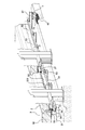
図1には台車式加熱炉の左右対称形状の下端部の、半部横断面図を示し、図2には、台車式加熱炉の下端部を側方から見た破断斜視図を示す。加熱炉Eの炉壁は全体として下方へ開放する略門型の断面を有し、図1、図2はその一方の側壁1の下端部を示している。側壁1の内側壁11(図1)は耐火物で構成されており、当該内側壁11の下端には、フレーム21上に耐火物22を形成して構成された庇壁2が、炉の内方へ向けて突設されている。
FIG. 1 shows a half cross-sectional view of the lower end portion of the left and right symmetrical shape of the cart type heating furnace, and FIG. 2 shows a cutaway perspective view of the lower end portion of the cart type heating furnace as viewed from the side. The furnace wall of the heating furnace E has a substantially gate-shaped cross section that opens downward as a whole, and FIGS. 1 and 2 show the lower end of one of the side walls 1. The inner wall 11 (FIG. 1) of the side wall 1 is made of a refractory material, and a
上記各図は炉内へ台車3を進入させた状態を示しており、台車3は加熱炉Eの左右の側壁1間に位置して当該加熱炉Eの開放部をほぼ閉鎖し、炉床を構成している。すなわち、台車3は水平姿勢のフレーム31を備え、当該フレーム31上に、所定厚の耐火物で構成された床壁32が形成されている。床壁32は庇壁2とほぼ同一高さに位置し、床壁32上にはスキットSに載せた大型鍛鋼品等の被加熱材Wが置かれている。
Each said figure has shown the state which made the trolley | bogie 3 approach into the furnace, and the trolley | bogie 3 is located between the right-and-left side walls 1 of the heating furnace E, closes the open part of the said heating furnace E, and closes the hearth. It is composed. In other words, the carriage 3 includes a
床壁32の外側縁は庇壁2の内側縁に接近して、これらの間に、途中で折れ線状に屈曲しつつ上下方向へ延びる間隙4が形成されている。フレーム31の下面には左右位置に(図1に一方のみ示す)それぞれ二条のレール体33が突設され、これらレール体33がローラー体35の両側小径軸部上に載置されている。ローラ体35は、加熱炉Eの前後方向(図1の紙面垂直方向)へ互いに連結材34で連結されて複数配設されている。ローラー体35はその中央大径部が、地表面に埋設したガイドレール36上に載置されて転動するようになっている。このような構造により、モータ駆動の図略のラックアンドピニオン機構によって台車3は図示の進入位置と、加熱炉E外へ引き出された(図1の紙面手前側ないし図2の左方)進出位置との間で移動させられる。
The outer edge of the
上記フレーム31の両側(図1に一方のみ示す)にはこれに沿ってシール材貯留槽51が設けられている。シール材貯留槽51は上方へ開放するU字断面をなしてフレーム31に沿って前後方向へ樋状に延びている(図2)。このシール材貯留槽51は上記間隙4(図1)の下方開口41の直下に位置している。シール材貯留槽51内には最初にシール材としてドロマイトの細粒61が一定高さまで収容されている。シール材貯留槽51内には上方からシール板52が挿入されて、その先端部(下端部)がドロマイト61層内に侵入している。
Sealing
シール板52は上端部521が水平に屈曲しており、この水平な上端部521がバネ部材53を周囲に配した支持ボルト(図示略)によって庇壁2のフレーム21上に支持されている。上記バネ部材53はシール板52を下方へ付勢するようなバネ力を発揮するように設定されている。シール板52の下端部にはこれに沿って長手方向へ図3に示すように丸棒材54が接合してあり、台車フレーム31の進出端ないし進入端たる丸棒材54の前後端(図3は前端を示す)541はそれぞれ斜め上方へ湾曲させてある。シール板52はシール材貯留槽61と同一長さでこれに沿って延びているが、長手方向の複数位置で分割されており、各分割部がそれぞれ、フレーム21上の複数位置に設けた、上記バネ部材53を配した支持ボルトで支持されて下方へ付勢されている。
The
シール材貯留槽51の下方の地表面には前後方向へピットPが設けてある。一方、台車フレーム31の進入端たる最後端位置には側方へ突出するアーム37が設けられてその下面にスクレーパ7が設けてある。スクレーパ7は掻き板71を備えており、当該掻き板71はピットP内に起立姿勢で位置している。掻き板71は上端がアーム37の下面に軸部材72(図1)によって回動可能に結合されて起立姿勢から前方へ跳ね上げ回動可能であるとともに、起立姿勢から後方への回動は図略のストッパによって規制されている。
A pit P is provided in the front-rear direction on the ground surface below the sealing
このような構造のシール装置において、初期のシールは、シール板52の下端部がシール材貯留槽51内のドロマイト61層に侵入していることによって外気と炉内が遮断されて確保される。ドロマイト61の細粒は台車3が炉内外への進出進入を繰り返す毎にシール材貯留槽51内から溢れて減少する。ここにおいて、台車3の移動時には床壁32上の被加熱材Wから剥離脱落したスケール62が間隙4を経てその下方に開口するシール材貯留槽51内に落下供給される(図1)。スケール62は屈曲した間隙4を落下する間に、当該間隙4を形成する台車床壁32の外側縁や庇壁2の内側縁に当たって砕かれ、小型化する。そしてさらに、シール材貯留槽51内に落下すると、バネ部材53によって下方へ付勢されているシール板52が、落下したスケール62に乗り上げつつ移動することによって押し潰されて細粒化ないし細片化される。この際、シール板52の下端部には、既述のように前端541および後端を斜め上方へ湾曲させた丸棒材54が接合してあるから摩擦抵抗が軽減されて、スケール62へのシール板52の乗り上げと乗り上げ状態での移動がスムーズに行われる。
In the sealing device having such a structure, the initial seal is ensured by blocking the outside air and the inside of the furnace by the lower end portion of the
細粒化・細片化されたスケール62はドロマイト61と同様のシール材として機能し、このようなスケール62中にシール板52の下端部が侵入していることによって外気と炉内が遮断されて気密性が保たれる。このように、シール材貯留槽51に最初に貯留されたドロマイト61が、台車3の炉内外への進出進入に伴ってシール材貯留槽51内から溢れ、減少しても、次々に落下供給されるスケール62がドロマイト61に代わってシール材として機能して、加熱炉Eのシール性が保たれる。このように、シール材を補充する手間を要さず、したがってシール材補充作業に伴う操業効率の低下を避けることができる。
The
シール材貯留槽51から溢れたドロマイト61やスケール62は下方のピットP内へ落下し収容される。ここにおいて本実施形態では、台車フレーム31の最後端位置にスクレーパ7を設けてあるから、台車3の炉外への進出移動の際に、スクレーパ7の掻き板71がピットP内を前方へ移動して、ここに収容されたドロマイト61やスケール62を前方の炉外へ掻き出す。
The
このようにして、台車3が炉外へ進出させられる毎にピットP内のスケール62等の除去がなされるから、除去作業の必要が無くなり、除去作業に伴う操業効率の低下が回避される。なお、掻き板71は前方への跳ね上げ回動は可能になっているから、台車3が炉内へ進入する際には掻き板71は適宜前方へ跳ね上がって、ピットP内のドロマイト61やスケール62を掻くことなく後端位置まで戻る。
In this way, every time the carriage 3 is moved out of the furnace, the
上記実施形態において、シール材貯留槽51を炉の側壁1側に設け、シール板52を台車3側に設けるようにしても良い。
In the said embodiment, you may make it provide the sealing
2…庇壁(側壁)、3…台車、51…シール材貯留槽、52…シール板、62…スケール、7…スクレーパ、71…掻き板、E…加熱炉、W…被加熱材、P…ピット。 2 ... Wall (side wall), 3 ... Cart, 51 ... Sealing material storage tank, 52 ... Sealing plate, 62 ... Scale, 7 ... Scraper, 71 ... Scraping plate, E ... Heating furnace, W ... Material to be heated, P ... pit.
Claims (2)
Priority Applications (1)
| Application Number | Priority Date | Filing Date | Title |
|---|---|---|---|
| JP2008191759A JP5338172B2 (en) | 2008-07-25 | 2008-07-25 | Heating furnace sealing device |
Applications Claiming Priority (1)
| Application Number | Priority Date | Filing Date | Title |
|---|---|---|---|
| JP2008191759A JP5338172B2 (en) | 2008-07-25 | 2008-07-25 | Heating furnace sealing device |
Publications (2)
| Publication Number | Publication Date |
|---|---|
| JP2010032064A true JP2010032064A (en) | 2010-02-12 |
| JP5338172B2 JP5338172B2 (en) | 2013-11-13 |
Family
ID=41736750
Family Applications (1)
| Application Number | Title | Priority Date | Filing Date |
|---|---|---|---|
| JP2008191759A Active JP5338172B2 (en) | 2008-07-25 | 2008-07-25 | Heating furnace sealing device |
Country Status (1)
| Country | Link |
|---|---|
| JP (1) | JP5338172B2 (en) |
Cited By (3)
| Publication number | Priority date | Publication date | Assignee | Title |
|---|---|---|---|---|
| CN102278885A (en) * | 2011-07-01 | 2011-12-14 | 段晓燕 | Furnace side wall for collecting gases in silicon carbide smelting furnace |
| KR200477943Y1 (en) * | 2015-01-15 | 2015-08-21 | 삼현테크(주) | heating apparatus |
| JP2018128179A (en) * | 2017-02-07 | 2018-08-16 | Dowaエコシステム株式会社 | Labyrinth seal structure, heat treatment furnace and heat treatment method |
Citations (8)
| Publication number | Priority date | Publication date | Assignee | Title |
|---|---|---|---|---|
| JPS54116505U (en) * | 1978-02-04 | 1979-08-15 | ||
| JPS6036878A (en) * | 1983-08-08 | 1985-02-26 | 株式会社トウネツ | Method of sealing hearth suitable for continuous use of truck furnace |
| JPH0392755U (en) * | 1990-01-12 | 1991-09-20 | ||
| JPH04270885A (en) * | 1991-02-25 | 1992-09-28 | Ngk Insulators Ltd | Truck sealing device for high-temperature baking furnace |
| JPH0518674A (en) * | 1991-07-12 | 1993-01-26 | Ngk Insulators Ltd | Sealing device for truck part in continuous furnace |
| JPH0673697U (en) * | 1993-03-29 | 1994-10-18 | 日本碍子株式会社 | Heat seal structure of firing cart |
| JPH1089852A (en) * | 1996-09-11 | 1998-04-10 | Murata Mfg Co Ltd | Continuous heat treatment furnace |
| JP2005009759A (en) * | 2003-06-18 | 2005-01-13 | Daido Steel Co Ltd | Sealing mechanism for heating furnace |
-
2008
- 2008-07-25 JP JP2008191759A patent/JP5338172B2/en active Active
Patent Citations (8)
| Publication number | Priority date | Publication date | Assignee | Title |
|---|---|---|---|---|
| JPS54116505U (en) * | 1978-02-04 | 1979-08-15 | ||
| JPS6036878A (en) * | 1983-08-08 | 1985-02-26 | 株式会社トウネツ | Method of sealing hearth suitable for continuous use of truck furnace |
| JPH0392755U (en) * | 1990-01-12 | 1991-09-20 | ||
| JPH04270885A (en) * | 1991-02-25 | 1992-09-28 | Ngk Insulators Ltd | Truck sealing device for high-temperature baking furnace |
| JPH0518674A (en) * | 1991-07-12 | 1993-01-26 | Ngk Insulators Ltd | Sealing device for truck part in continuous furnace |
| JPH0673697U (en) * | 1993-03-29 | 1994-10-18 | 日本碍子株式会社 | Heat seal structure of firing cart |
| JPH1089852A (en) * | 1996-09-11 | 1998-04-10 | Murata Mfg Co Ltd | Continuous heat treatment furnace |
| JP2005009759A (en) * | 2003-06-18 | 2005-01-13 | Daido Steel Co Ltd | Sealing mechanism for heating furnace |
Cited By (3)
| Publication number | Priority date | Publication date | Assignee | Title |
|---|---|---|---|---|
| CN102278885A (en) * | 2011-07-01 | 2011-12-14 | 段晓燕 | Furnace side wall for collecting gases in silicon carbide smelting furnace |
| KR200477943Y1 (en) * | 2015-01-15 | 2015-08-21 | 삼현테크(주) | heating apparatus |
| JP2018128179A (en) * | 2017-02-07 | 2018-08-16 | Dowaエコシステム株式会社 | Labyrinth seal structure, heat treatment furnace and heat treatment method |
Also Published As
| Publication number | Publication date |
|---|---|
| JP5338172B2 (en) | 2013-11-13 |
Similar Documents
| Publication | Publication Date | Title |
|---|---|---|
| BR112018077274B1 (en) | BEARING TREATMENT PROCESS AND BEARING TREATMENT DEVICE FOR FULL QUANTITY STEEL SLAG TREATMENT | |
| JP5338172B2 (en) | Heating furnace sealing device | |
| CN103180466B (en) | Charging shaft system and method for filling | |
| KR101461746B1 (en) | Inoxidizable Gas Wiping Apparatus | |
| JP6845637B2 (en) | Panel loading rack | |
| ES2662745T3 (en) | Procedure to remove scrap linings | |
| JP4866598B2 (en) | Wet ash extrusion equipment | |
| JP6264712B2 (en) | Incineration ash cooling device | |
| FI104381B (en) | Dispenser for an electric oven | |
| JP5521773B2 (en) | Molten steel pouring apparatus and pouring method | |
| JP2014513202A (en) | How to treat aluminum slag | |
| CN214557219U (en) | Hot metal bottle adds steel scrap buffer | |
| JP2008147075A (en) | Electrolytic liquid separation device | |
| JP6697527B2 (en) | Film forming apparatus and film forming method | |
| CN212092435U (en) | Dangerous waste slag conveyer | |
| JP5397736B2 (en) | Float glass manufacturing apparatus and float glass manufacturing method | |
| JP4327124B2 (en) | Safety measures system for molten metal | |
| JP4280905B2 (en) | Slag carry-out conveyor | |
| JP3847107B2 (en) | Slag conveyor | |
| KR101647145B1 (en) | Highly efficient deslagging method | |
| CN106219224B (en) | A kind of convertible railing prosthetic device of painting workshop ventilator hole cover | |
| CN215113962U (en) | Automatic feeding device for aluminum ingot melting furnace | |
| JP6124457B2 (en) | Floor cargo conveyor | |
| KR20120057325A (en) | Apparatus for preventing slag pot transferring car from stucking | |
| RU129111U1 (en) | SNOW DRINKER WITH MECHANISM FOR UNLOADING GARBAGE AND SEDIMENTS |
Legal Events
| Date | Code | Title | Description |
|---|---|---|---|
| A621 | Written request for application examination |
Free format text: JAPANESE INTERMEDIATE CODE: A621 Effective date: 20110526 |
|
| TRDD | Decision of grant or rejection written | ||
| A01 | Written decision to grant a patent or to grant a registration (utility model) |
Free format text: JAPANESE INTERMEDIATE CODE: A01 Effective date: 20130709 |
|
| A61 | First payment of annual fees (during grant procedure) |
Free format text: JAPANESE INTERMEDIATE CODE: A61 Effective date: 20130722 |
|
| R150 | Certificate of patent or registration of utility model |
Ref document number: 5338172 Country of ref document: JP Free format text: JAPANESE INTERMEDIATE CODE: R150 Free format text: JAPANESE INTERMEDIATE CODE: R150 |