JP2010032048A - Anchor element - Google Patents
Anchor element Download PDFInfo
- Publication number
- JP2010032048A JP2010032048A JP2009171551A JP2009171551A JP2010032048A JP 2010032048 A JP2010032048 A JP 2010032048A JP 2009171551 A JP2009171551 A JP 2009171551A JP 2009171551 A JP2009171551 A JP 2009171551A JP 2010032048 A JP2010032048 A JP 2010032048A
- Authority
- JP
- Japan
- Prior art keywords
- anchor element
- strip
- anchor
- shaft
- fixing
- Prior art date
- Legal status (The legal status is an assumption and is not a legal conclusion. Google has not performed a legal analysis and makes no representation as to the accuracy of the status listed.)
- Granted
Links
- 239000000463 material Substances 0.000 claims description 55
- 238000004804 winding Methods 0.000 description 12
- 238000005553 drilling Methods 0.000 description 5
- 238000004140 cleaning Methods 0.000 description 3
- 239000002184 metal Substances 0.000 description 3
- 238000000034 method Methods 0.000 description 3
- 239000004033 plastic Substances 0.000 description 3
- 229920003023 plastic Polymers 0.000 description 3
- 229920002430 Fibre-reinforced plastic Polymers 0.000 description 2
- 229910000831 Steel Inorganic materials 0.000 description 2
- 239000012080 ambient air Substances 0.000 description 2
- 238000004873 anchoring Methods 0.000 description 2
- 238000005452 bending Methods 0.000 description 2
- 239000011151 fibre-reinforced plastic Substances 0.000 description 2
- 238000002347 injection Methods 0.000 description 2
- 239000007924 injection Substances 0.000 description 2
- 238000001746 injection moulding Methods 0.000 description 2
- 230000002787 reinforcement Effects 0.000 description 2
- 239000010959 steel Substances 0.000 description 2
- 241000736305 Marsilea quadrifolia Species 0.000 description 1
- 230000001154 acute effect Effects 0.000 description 1
- 230000008878 coupling Effects 0.000 description 1
- 238000010168 coupling process Methods 0.000 description 1
- 238000005859 coupling reaction Methods 0.000 description 1
- 238000005520 cutting process Methods 0.000 description 1
- 230000001419 dependent effect Effects 0.000 description 1
- 230000000694 effects Effects 0.000 description 1
- 230000007257 malfunction Effects 0.000 description 1
- 238000004519 manufacturing process Methods 0.000 description 1
- 239000012811 non-conductive material Substances 0.000 description 1
- 238000004080 punching Methods 0.000 description 1
- 238000005476 soldering Methods 0.000 description 1
- 239000000243 solution Substances 0.000 description 1
- 239000000758 substrate Substances 0.000 description 1
- 238000003466 welding Methods 0.000 description 1
Images


Classifications
-
- F—MECHANICAL ENGINEERING; LIGHTING; HEATING; WEAPONS; BLASTING
- F16—ENGINEERING ELEMENTS AND UNITS; GENERAL MEASURES FOR PRODUCING AND MAINTAINING EFFECTIVE FUNCTIONING OF MACHINES OR INSTALLATIONS; THERMAL INSULATION IN GENERAL
- F16B—DEVICES FOR FASTENING OR SECURING CONSTRUCTIONAL ELEMENTS OR MACHINE PARTS TOGETHER, e.g. NAILS, BOLTS, CIRCLIPS, CLAMPS, CLIPS OR WEDGES; JOINTS OR JOINTING
- F16B37/00—Nuts or like thread-engaging members
- F16B37/12—Nuts or like thread-engaging members with thread-engaging surfaces formed by inserted coil-springs, discs, or the like; Independent pieces of wound wire used as nuts; Threaded inserts for holes
-
- F—MECHANICAL ENGINEERING; LIGHTING; HEATING; WEAPONS; BLASTING
- F16—ENGINEERING ELEMENTS AND UNITS; GENERAL MEASURES FOR PRODUCING AND MAINTAINING EFFECTIVE FUNCTIONING OF MACHINES OR INSTALLATIONS; THERMAL INSULATION IN GENERAL
- F16B—DEVICES FOR FASTENING OR SECURING CONSTRUCTIONAL ELEMENTS OR MACHINE PARTS TOGETHER, e.g. NAILS, BOLTS, CIRCLIPS, CLAMPS, CLIPS OR WEDGES; JOINTS OR JOINTING
- F16B39/00—Locking of screws, bolts or nuts
- F16B39/02—Locking of screws, bolts or nuts in which the locking takes place after screwing down
- F16B39/021—Locking of screws, bolts or nuts in which the locking takes place after screwing down by injecting a settable material after the screwing down
-
- F—MECHANICAL ENGINEERING; LIGHTING; HEATING; WEAPONS; BLASTING
- F16—ENGINEERING ELEMENTS AND UNITS; GENERAL MEASURES FOR PRODUCING AND MAINTAINING EFFECTIVE FUNCTIONING OF MACHINES OR INSTALLATIONS; THERMAL INSULATION IN GENERAL
- F16B—DEVICES FOR FASTENING OR SECURING CONSTRUCTIONAL ELEMENTS OR MACHINE PARTS TOGETHER, e.g. NAILS, BOLTS, CIRCLIPS, CLAMPS, CLIPS OR WEDGES; JOINTS OR JOINTING
- F16B39/00—Locking of screws, bolts or nuts
- F16B39/02—Locking of screws, bolts or nuts in which the locking takes place after screwing down
- F16B39/20—Locking of screws, bolts or nuts in which the locking takes place after screwing down by means of steel wire or the like
Abstract
Description
本発明は、固定素子における外形付与部を設けたシャフトに配置され、シャフトのための貫通開口を有するアンカ素子に関する。さらに本発明は、硬化可能材料によりドリル孔内に係止可能であり、少なくとも1つの上記アンカ素子を有する固定装置、ならびにこのような固定装置を備える固定システムに関する。 The present invention relates to an anchor element that is disposed on a shaft provided with an outer shape imparting portion in a fixed element and has a through opening for the shaft. The invention further relates to a fixing device which can be locked in the drill hole by a curable material and has at least one anchor element as well as a fixing system comprising such a fixing device.
外形付与部を有するシャフトを備える固定素子を硬化可能材料によってドリル孔内に化学的に係止させることが公知である。硬化可能材料は、固定素子をドリル孔内に導入する前または導入した後にドリル孔内に挿入される。固定素子は、例えば外形付与部として全長にわたってねじ山を設けたねじ山付ロッドである。固定素子が化学的に係止される場合には、シャフトと硬化された材料との間の接触領域に沿って、またはドリル孔壁と硬化された材料との間の接触領域に沿って固定箇所に機能不良が生じる場合がある。 It is known to chemically lock a fixing element comprising a shaft with a contouring portion into a drill hole with a curable material. The curable material is inserted into the drill hole before or after the fixation element is introduced into the drill hole. The fixing element is, for example, a threaded rod provided with a thread over the entire length as an outer shape imparting part. If the fastening element is chemically locked, the fastening point is along the contact area between the shaft and the hardened material or along the contact area between the drill hole wall and the hardened material. May malfunction.
ドリル孔および特にドリル孔壁を清掃することにより、ドリル孔壁における硬化材料の付着、ひいてはドリル孔内における固定素子の係止を改善することができる。ドリル孔の清掃により特に良好な結果を得るためには、使用者が必ずしも入手できない別個の補助手段を必要とする付加的な作業の手間が生じる。 By cleaning the drill hole and in particular the drill hole wall, it is possible to improve the adhesion of the hardened material on the drill hole wall and thus the locking of the fixing element in the drill hole. In order to obtain particularly good results by cleaning the drill holes, additional work is required which requires separate auxiliary means not necessarily available to the user.
ドイツ国特許第2423433号明細書により、硬化可能材料によってドリル孔内に係止可能な、アンカロッドの形態をした固定素子が公知である。このアンカロッドは、ねじ切りされていない部分に半径方向に突出するブラシを有し、このブラシは、硬化可能材料を充填されたドリル孔に固定素子が導入される場合にドリル孔壁を清掃する。 German Patent No. 2423433 discloses a fixing element in the form of an anchor rod which can be locked in a drill hole by a curable material. The anchor rod has a radially projecting brush on the non-threaded part, which cleans the drill hole wall when a fixing element is introduced into the drill hole filled with curable material.
公知の手段では、固定素子が硬化可能材料の硬化後にはじめて負荷可能であることが欠点である。 A disadvantage of the known means is that the fixing element can only be loaded after the curable material has been cured.
米国特許第1,688,087号明細書により、硬化可能材料によってドリル孔内に係止可能な固定装置が公知である。この固定装置は、外形付与部としてねじ山を有するシャフト備える固定素子と、シャフトのためにそれぞれ1つの貫通開口を備える複数の環状ディスク型アンカ素子とを有する。アンカ素子はそれぞれドリル孔の公称径よりも大きい外径を有する。固定装置はドリル孔内に導入される。環状ディスク型アンカ素子は、例えば固定装置の導入前後に挿入される硬化可能材料が固定装置をドリル孔内に係止させるために十分に硬化されるまで固定素子をドリル孔内に機械的に係止させる。さらにアンカ素子は硬化された材料を補強し、付加的により高い引抜き耐力を可能とする。 U.S. Pat. No. 1,688,087 discloses a fixing device that can be locked in a drill hole by a curable material. The fixing device includes a fixing element including a shaft having a thread as an outer shape imparting portion, and a plurality of annular disk type anchor elements each having one through opening for the shaft. Each anchor element has an outer diameter larger than the nominal diameter of the drill hole. The fixing device is introduced into the drill hole. Annular disk anchor elements are mechanically engaged in the drilling element until the curable material inserted, for example, before and after the introduction of the fixing device is sufficiently cured to lock the fixing device in the drill hole. Stop. In addition, the anchor element reinforces the cured material and allows additional higher pulling strength.
公知の解決手段では、シャフトの外形付与部により、環状ディスク型アンカ素子が、配置された状態でシャフト長さ方向軸線に関して垂直な平面に対してわずかに傾いており、それ故、ドリル孔から突出したシャフト部分が固定装置の打込み後に構成部分の表面から垂直に突出しないことが欠点である。シャフトの後調整は可能であっても限定的にのみ可能である。なぜなら、シャフトの後調整は、少なくとも1つのアンカ素子により生成される対向力に抗して行わなければならないからである。 In the known solution, the contouring part of the shaft causes the annular disk-type anchor element to be slightly inclined with respect to a plane perpendicular to the shaft longitudinal axis in the arranged state and therefore protrudes from the drill hole. It is a disadvantage that the shaft part which has been made does not protrude vertically from the surface of the component part after the fixing device has been driven. Post-adjustment of the shaft is possible but only limited. This is because the post-adjustment of the shaft must be performed against the opposing force generated by the at least one anchor element.
本発明の課題は、外形付与部を設けたシャフトを有する固定素子に簡単に取り付けることができ、固定装置打込みの手間が減じられたアンカ素子を提案することである。さらに少なくとも1つのアンカ素子を備える固定素子を有する化学的に係止可能な固定装置、および、このような固定装置を備え、打込みの手間を減じた固定システムを提案することである。 An object of the present invention is to propose an anchor element that can be easily attached to a fixing element having a shaft provided with an outer shape imparting portion and that reduces the trouble of driving a fixing device. Furthermore, it is to propose a chemically lockable fixing device having a fixing element comprising at least one anchor element, and a fixing system comprising such a fixing device and with reduced driving effort.
この課題は、独立請求項に記載の特徴を有するアンカ素子、固定装置および固定システムにより解決される。さらなる有利な実施形態が従属請求項に記載されている。 This problem is solved by an anchor element, a fixing device and a fixing system having the features described in the independent claims. Further advantageous embodiments are described in the dependent claims.
本発明によれば、アンカ素子は、360°を超える角度範囲にわたって貫通開口の周りに延在する帯状片によって形成されている。 According to the invention, the anchor element is formed by a strip extending around the through-opening over an angular range exceeding 360 °.
帯状片は、組み付けられた状態で固定素子のシャフトを少なくとも一周は完全に取り囲み、帯状片の半径方向内縁は少なくとも部分的にシャフトの外形付与部に係合する。有利には、帯状片は360°の数倍の角度範囲にわたって貫通開口の周りに延在している。帯状片として形成されたアンカ素子により、シャフトにおける外形付与部の勾配を補償することができる。少なくとも1つのアンカ素子を有する固定素子をドリル孔への打込み後に調整することは、多くの場合には不要であるか、または容易に行うことができる。 In the assembled state, the strips completely surround the shaft of the fixing element at least once, and the radially inner edge of the strips at least partially engages the contouring part of the shaft. Advantageously, the strips extend around the through-opening over an angular range several times 360 °. An anchor element formed as a strip can compensate for the gradient of the outer shape imparting portion in the shaft. It is often unnecessary or easy to adjust the fixing element having at least one anchor element after being driven into the drill hole.
貫通開口は、有利には固定素子のシャフトに適合させた形状を有しており、したがって、円とは異なる構成を有していてもよい。有利には、帯状片は長さに沿って一定の幅を有し、貫通開口は、アンカ素子の外周または帯状片の半径方向外縁を形成する輪郭線に対して同心的に配置されている。代替的な構成では、帯状片は長さに沿って可変の幅を有しており、これにより、貫通開口の半径方向境界と、アンカ素子の外周を形成する輪郭線との間で材料部分の幅は周方向に変化する。 The through opening advantageously has a shape adapted to the shaft of the fixing element and may therefore have a different configuration from the circle. Advantageously, the strip has a constant width along its length, and the through-openings are arranged concentrically with respect to the contour line forming the outer periphery of the anchor element or the radial outer edge of the strip. In an alternative configuration, the strip has a variable width along its length, so that the material portion between the radial boundary of the through-opening and the contour that forms the outer periphery of the anchor element. The width varies in the circumferential direction.
有利には、帯状片はコイル状に形成されており、これにより、弦巻状の外形を有している。このアンカ素子は、固定素子のシャフトに簡単に配置することができる。帯状片の勾配は、有利にはシャフトの外形付与部に場合によっては設けられている勾配よりも大きく選択される。コイル状の帯状片の勾配に関連して、ドリル孔に打ち込まれた状態の固定素子の有利な案内または配向が得られる。 Advantageously, the strip is formed in a coil shape and thereby has a chord-like profile. This anchor element can be easily arranged on the shaft of the fixed element. The gradient of the strip is preferably selected to be greater than the gradient that is possibly provided in the outer contouring part of the shaft. In connection with the gradient of the coiled strip, an advantageous guide or orientation of the fixing element in the state of being driven into the drill hole is obtained.
好ましくは帯状片は非円形の外形を有しており、この外形は360°の角度範囲にわたって少なくとも2つの変曲点を有しており、したがって外形は周方向にドリル孔壁に完全に当接していない。このようなアンカ素子を有する固定素子の導入時には、アンカ素子の一部のみがドリル孔壁に沿って滑動し、これにより、より小さい力、ひいてはよりわずかな手間が固定素子を打ち込むために必要となる。平面図において外形に2つの変曲点が設けらた楕円形の構成の他に、帯状片は外形に3つ以上の変曲点が設けられた構成を有していてもよい。有利には、変曲点のコーナは丸く形成されている。さらに有利には、2つの変曲点の間の帯状片部分はアーチ状に延びている。 Preferably the strip has a non-circular contour, which has at least two inflection points over an angular range of 360 °, so that the contour is in full contact with the drill hole wall in the circumferential direction. Not. At the time of introducing a fixing element having such an anchor element, only a part of the anchor element slides along the drill hole wall, which requires less force and thus less effort to drive the fixing element. Become. In addition to an elliptical configuration in which two inflection points are provided in the outer shape in the plan view, the strip may have a configuration in which three or more inflection points are provided in the outer shape. Advantageously, the corner of the inflection point is rounded. More advantageously, the strip portion between the two inflection points extends in an arch shape.
好ましくは、帯状片は、非円形の外形に対して付加的に、360°の角度範囲にわたって少なくとも2つの変曲点を有する非円形の内形を有しており、これにより、帯状片は、部分的にのみ固定素子のシャフトに当接し、シャフトの外面に対して部分的に離間されている。シャフトに対して離間された帯状片部分の領域には硬化可能材料のための貫通開口が形成される。2つの変曲点が設けられた平面図で見て楕円形の内形の構成の他に、帯状片は3つ以上の変曲点が設けられた内形の構成を有していてもよい。有利には、変曲点は丸く形成されている。さらに有利には、2つの変曲点の間の帯状片部分はアーチ状に延びている。 Preferably, the strip has a non-circular inner shape with at least two inflection points over an angular range of 360 ° in addition to the non-circular contour, whereby the strip is It only partially contacts the shaft of the fixing element and is partially spaced from the outer surface of the shaft. A through-opening for the curable material is formed in the region of the strip-shaped portion spaced from the shaft. In addition to the elliptical inner shape as seen in a plan view provided with two inflection points, the strip may have an inner shape configuration with three or more inflection points. . Advantageously, the inflection point is rounded. More advantageously, the strip portion between the two inflection points extends in an arch shape.
好ましくは、帯状片の隣接する2つの巻き部の変曲点は、互いに角度差をもって配置されており、これにより、打込みのために小さい力を加えるだけでドリル孔壁が有利に清掃されることが保証されている。このことは、帯状片におけるドリル孔壁に当接する部分が帯状片の長さにわたって半径方向に分配して配置されていることによって確保される。 Preferably, the inflection points of two adjacent windings of the strip are arranged at an angular difference from each other, so that the drill hole wall is advantageously cleaned with only a small force for driving. Is guaranteed. This is ensured by the portion of the strip that abuts against the drill hole wall being distributed in the radial direction over the length of the strip.
有利には、この角度差は次の式、
α=360・n/ξ・ω[°]
に従って規定され、この場合、
nは、帯状片の巻き部の半径方向外側とドリル孔壁との望ましい繰返し接触の回数であり、有利には、巻き部毎に2回以上の繰返し接触が生じ、
ξは、平面図において360°にわたる巻き部の総数またはその関数であり、式:
ξ=hHelix/PHelix
が成り立ち、
hHelixは、帯状片の軸線方向全高であり、
PHelixは、帯状片の巻き部の勾配であり、
ωは、平面図で見て360°にわたる巻き部の変曲点の数である。帯状片が平面図において楕円状の構成を有している場合、変曲点の数は2個である。対応して変曲点の数は、三角形では3個、四角形は4個、四つ葉クローバ状では4個、五角形では5個、等であり、
αは、角度差、すなわち、帯状片の隣接する2つの巻き部の変曲点が互いにずらされる角度である。
Advantageously, this angular difference is given by
α = 360 · n / ξ · ω [°]
In this case,
n is the number of desired repeated contacts between the radially outer side of the winding of the strip and the drill hole wall, advantageously, two or more repeated contacts occur per winding,
ξ is the total number of windings over 360 ° in the plan view or a function thereof,
ξ = h Helix / P Helix
And
h Helix is the total axial height of the strips;
P Helix is the slope of the winding of the strip,
ω is the number of inflection points of the winding portion over 360 ° as seen in the plan view. When the strip has an elliptical configuration in the plan view, the number of inflection points is two. Correspondingly, the number of inflection points is 3 for the triangle, 4 for the square, 4 for the four-leaf clover, 5 for the pentagon, etc.
α is an angle difference, that is, an angle at which the inflection points of two adjacent winding portions of the strip are shifted from each other.
本発明による代替的な実施形態では、帯状片は、互いに隣接する周方向部分または縁部分で互いに結合された複数の環状ディスク型素子部分を有する。有利には、これらの環状ディスク型素子は、それぞれ互いに半径方向に向かい合った周方向部分で互いに結合されてアンカ素子をなし、これにより、アンカ素子は、アコーディオン状に圧縮または延伸させることにより、例えば固定素子の係止長さに適合させるために長さを調整することができる。固定素子のシャフトのための貫通開口は、環状ディスク型素子部分の内側開口により形成されている。環状ディスク型素子部分は、例えば一体的に形成されており、アンカ素子の形成時に相応に折りたたまれる。代替的な構成では、環状ディスク型素子部分は固定箇所、例えばはんだ付けもしくは接着箇所で、またはクランプもしくは保持手段によって互いに結合されている。 In an alternative embodiment according to the present invention, the strip has a plurality of annular disc-shaped element portions joined together at circumferential portions or edge portions adjacent to each other. Advantageously, these annular disk-type elements are joined together at circumferential portions that are radially opposite each other to form an anchor element, whereby the anchor element is compressed or stretched in an accordion manner, for example The length can be adjusted to match the locking length of the fixing element. The through-opening for the shaft of the fixing element is formed by the inner opening of the annular disk-type element part. The annular disk-type element part is formed integrally, for example, and is folded accordingly when the anchor element is formed. In an alternative arrangement, the annular disk-shaped element parts are coupled to each other at a fixed location, such as a soldered or bonded location, or by a clamp or holding means.
好ましくは、帯状片の半径方向外縁には形状付与部が設けられており、この形状付与部は、アンカ素子をドリル孔の構成に簡単に適合させることを保証する。例えば、形状付与部は半径方向外向きに開口した切欠きによって形成される。有利には、これらの切欠きは一方側で制限されたスリットとして形成されており、これらのスリットは、外縁を起点として貫通開口の方向に延在している。切欠きの間に位置するアンカ素子部分は、容易に変位可能なフィンを形成しており、これにより、極めて堅固な材料からなるアンカ素子においてもドリル孔内への導入時にドリル孔への適合性が得られる。さらに有利には、異なる種類の切欠きがアンカ素子の外縁に設けられている。例えば、外縁で可動なフィンを形成する第1のスリットが設けられており、これらの第1のスリットの間には、第1のスリットの間に位置するアンカ素子縁部を拡開する第2のスリットが設けられている。 Preferably, a shape imparting portion is provided at the radially outer edge of the strip, which ensures that the anchor element is easily adapted to the drill hole configuration. For example, the shape imparting portion is formed by a notch opened outward in the radial direction. Advantageously, these notches are formed as slits restricted on one side, and these slits extend in the direction of the through-opening from the outer edge. The anchor element part located between the notches forms an easily displaceable fin, so that even anchor elements made of extremely rigid materials can be fitted into the drill hole when introduced into the drill hole. Is obtained. More advantageously, different types of notches are provided on the outer edge of the anchor element. For example, a first slit that forms a movable fin at the outer edge is provided, and a second edge that expands the edge of the anchor element located between the first slits is provided between the first slits. Slits are provided.
好ましくは、帯状片の半径方向内縁には形状付与部が設けられており、この形状付与部は、アンカ素子がシャフトの外形付与部の構成に簡単に適合されることを保証する。例えば、形状付与部は、半径方向内向きに開放された切欠きにより形成される。有利には、これらの切欠きは一方側が制限されたスリットとして形成され、これらのスリットは、内縁を起点として帯状片の外縁に向けて半径方向外方に延在している。切欠きの間に位置するアンカ素子部分は容易に変位可能なフィンを形成しており、これにより、極めて堅固な材料からなるアンカ素子においてもアンカ素子を固定素子に配置する場合に固定素子のシャフトへの適合性が得られる。さらに有利には、異なる種類の切欠きがアンカ素子の内縁に設けられている。例えば、内縁で可動なフィンを形成する第1のスリットが設けられており、これらの第1のスリットの間には、第1のスリットの間に位置する帯状片縁部を拡開する第2のスリットが設けられている。 Preferably, a shape imparting portion is provided on the radially inner edge of the strip, which ensures that the anchor element is easily adapted to the configuration of the shaft contour imparting portion. For example, the shape imparting portion is formed by a notch opened inward in the radial direction. Advantageously, these notches are formed as slits restricted on one side, these slits extending radially outward from the inner edge towards the outer edge of the strip. The anchor element portion located between the notches forms a fin that can be easily displaced, so that even in an anchor element made of a very rigid material, the anchor element shaft is arranged when the anchor element is arranged on the fixed element. Conformity to is obtained. More advantageously, different types of notches are provided at the inner edge of the anchor element. For example, the 1st slit which forms the fin which can move at an inner edge is provided, and the 2nd which expands the strip-like one edge part located between the 1st slits between these 1st slits. Slits are provided.
アンカ素子の有利で柔軟な構成では、帯状片の内縁および外縁にそれぞれ形状付与部が設けられており、これらの形状付与部は、半径方向に少なくとも部分的にオーバラップしていてもよい。 In an advantageous and flexible configuration of the anchor element, shape-imparting portions are respectively provided at the inner and outer edges of the strip, and these shape-imparting portions may at least partially overlap in the radial direction.
有利には、帯状片は長さに沿って波状の構成を有しており、これにより、特にドリル孔内への導入時にアンカ素子の十分な剛性が保証される。帯状片の波形は、例えば縦延在方向および/または横延在方向に設けられている。 Advantageously, the strip has a wave-like configuration along its length, which ensures sufficient rigidity of the anchor element, especially when introduced into the drill hole. The waveform of the strip is provided in, for example, the longitudinally extending direction and / or the laterally extending direction.
アンカ素子をドリル孔壁に有利に係止させるためには、帯状片の厚さは、有利には0.01mm〜2mm、特に有利には0.05mm〜1mmである。 In order to advantageously lock the anchor element to the drill hole wall, the thickness of the strip is preferably from 0.01 mm to 2 mm, particularly preferably from 0.05 mm to 1 mm.
有利には、帯状片は帯状片面において異なった厚さを有し、これにより、特にドリル孔内への導入時にはアンカ素子の変形特性を有利に調整することができる。特に有利な構成では、厚さは貫通開口を起点として半径方向外方に増大し、これにより、アンカ素子とドリル孔壁との接触領域には固定素子を機械的に係止させるために大量の材料が提供されている。別の有利な構成では、厚さは外縁を起点として半径方向に貫通開口に向けて増大しており、これにより、アンカ素子とシャフトとの接触領域においてアンカ素子をシャフトに固定するために有利には大量の材料がシャフトに提供される。さらに帯状片の厚さは、一方では貫通開口を起点として半径方向外方に、かつ他方では外縁を起点として半径方向に貫通開口に向けて増大しており、したがって、最大材料厚さを有する帯状片の領域が帯状片の外縁と内縁との間に位置している。 Advantageously, the strips have different thicknesses on the strip surface, so that the deformation characteristics of the anchor element can be advantageously adjusted, especially when introduced into the drill hole. In a particularly advantageous configuration, the thickness increases radially outwardly starting from the through-opening, so that a large amount of the locking element is mechanically locked in the contact area between the anchor element and the drill hole wall. Material is provided. In another advantageous configuration, the thickness increases radially from the outer edge towards the through opening, which is advantageous for securing the anchor element to the shaft in the area of contact between the anchor element and the shaft. A large amount of material is provided to the shaft. Furthermore, the thickness of the strips increases on the one hand radially outwardly starting from the through-opening and on the other hand radially towards the through-opening starting from the outer edge, and thus has the maximum material thickness. The strip region is located between the outer and inner edges of the strip.
好ましくは、帯状片には、硬化可能材料のための少なくとも1つの貫通開口が設けられており、これにより、アンカ素子の導入時に、硬化可能材料をあらかじめ充填されたドリル孔内にアンカ素子を導入する場合に、硬化可能材料の押しのけられた部分が進入し、アンカ素子を完全に覆うことができる。固定素子の導入後にドリル孔に硬化可能材料が充填される場合には、少なくとも1つの貫通開口により、注入された材料の大部分は妨げられずにドリル孔底部まで流れることができる。有利な構成では、少なくとも1つの貫通開口がアンカ素子の外周に設けられている。これに対して代替的または補足的に、アンカ素子または帯状片面に硬化可能材料のための少なくとも1つの周方向に閉じられた貫通開口が設けられる。特に有利には、複数の貫通開口が、帯状片の縦方向長さに沿って互いに離間して設けられており、さらに有利には、複数の巻き部に関して巻き部から巻き部へ互いにずらして配置されており、これにより、硬化された材料内における有利な係止および硬化された材料の補強が保証されている。 Preferably, the strip is provided with at least one through-opening for the curable material, so that when the anchor element is introduced, the anchor element is introduced into a drill hole prefilled with the curable material. In doing so, the displaced portion of the curable material can enter and completely cover the anchor element. If the drill hole is filled with a curable material after introduction of the fixing element, at least one through-opening allows most of the injected material to flow unimpeded to the bottom of the drill hole. In an advantageous configuration, at least one through opening is provided on the outer periphery of the anchor element. Alternatively or additionally, the anchor element or strip is provided with at least one circumferentially closed through opening for the curable material. Particularly preferably, the plurality of through-openings are provided spaced apart from one another along the longitudinal length of the strip, and more preferably with respect to the plurality of windings being offset from one another from the winding part to the winding part. This ensures advantageous locking within the cured material and reinforcement of the cured material.
有利には、帯状片は金属からなっており、有利には鋼薄板から作製されており、これにより、アンカ素子は十分な剛性を有している。アンカ素子の簡単で経済的な作製を、特に打抜き/曲げ加工方法により保証することができる。代替的に、帯状のアンカ素子は巻取り法により作製される。 Advantageously, the strip is made of metal, preferably made of steel sheet, so that the anchor element is sufficiently rigid. A simple and economical production of the anchor element can be ensured in particular by the stamping / bending method. Alternatively, the band-shaped anchor element is produced by a winding method.
代替的な有利な実施形態では、帯状片はプラスチック、有利には繊維強化プラスチックにより作製されている。特に射出成形法によりアンカ素子の簡単かつ経済的な作製を確実に行うことができる。 In an alternative advantageous embodiment, the strip is made of plastic, preferably fiber-reinforced plastic. In particular, the anchor element can be easily and economically produced by injection molding.
別の有利な構成では、アンカ素子は非導電性材料により作製されている。電流が伝達されることが不都合である用途、例えば鉄道枕木の固定時には、この帯状のアンカ素子は、シャフトとドリル孔壁と間に十分な間隔が得られることを保証し、構成部分から固定素子のシャフトに電流が流れることを阻止する。 In another advantageous configuration, the anchor element is made of a non-conductive material. In applications where current is not convenient, for example when fixing railway sleepers, this strip-shaped anchor element ensures that there is sufficient clearance between the shaft and the drill hole wall, and the fixed element from the component To prevent current from flowing through the shaft.
代替的な構成では、硬化可能材料が硬化するまでドリル孔内に固定素子が機械的に十分に係止されることを保証するものであれば、帯状片は金属またはプラスチックとは異なる材料から作製されていてもよい。 In an alternative configuration, the strip is made from a different material than metal or plastic, as long as it ensures that the securing element is mechanically locked in the drill hole until the curable material is cured. May be.
本発明による、硬化可能材料によりドリル孔内に係止可能な固定装置は、外形付与部を設けたシャフトを備える固定素子と、シャフトのための貫通開口を備える少なくとも1つのアンカ素子とを有し、アンカ素子は、360°を超える角度範囲にわたって貫通開口の周りに延在する帯状片により形成されている。 A fixing device according to the invention, which can be locked in a drill hole by a curable material, comprises a fixing element comprising a shaft provided with a contouring part and at least one anchor element comprising a through opening for the shaft. The anchor element is formed by a strip that extends around the through-opening over an angular range of more than 360 °.
固定装置は、容易に作製することができ、構成部分、例えば壁または天井のドリル孔内に簡単に取り付けることができる。固定素子のシャフトの外形付与部は、例えばねじ山である。 The fixation device can be easily made and can be easily installed in a component, for example, a drill hole in a wall or ceiling. The outer shape imparting part of the shaft of the fixing element is, for example, a screw thread.
固定装置の少なくとも1つの帯状アンカ素子は、上記アンカ素子の特徴を個々に、または全て有していてよい。 At least one strip anchor element of the anchoring device may have the characteristics of the anchor element individually or all.
好ましくは、複数のアンカ素子は互いに間隔をおいて固定素子に設けられており、これにより、固定素子の有利な機械的係止、ドリル孔内における固定素子の簡単な整列、ならびに硬化された材料の有利な補強が保証されている。 Preferably, the plurality of anchor elements are provided on the fixing element at a distance from one another so that an advantageous mechanical locking of the fixing element, simple alignment of the fixing element in the drill hole, as well as hardened material The advantageous reinforcement of is guaranteed.
好ましくは、固定素子に種々異なった構成のアンカ素子が設けられており、必要に応じて異なった係止深さで異なった係止特性を互いに組み合わせることもできる。例えば、帯状アンカ素子とスリーブ状または環状ディスク型アンカ素子とが1つのシャフトにおいて組み合わされる。 Preferably, anchor elements of different configurations are provided on the fixing element, and different locking characteristics can be combined with each other at different locking depths as required. For example, a band-shaped anchor element and a sleeve-shaped or annular disk-type anchor element are combined in one shaft.
硬化可能材料により公称径(N)を有するドリル孔内に固定装置を係止させるための本発明による固定システムは、固定素子と、固定素子に配置された少なくとも1つのアンカ素子とを備える固定装置を有し、アンカ素子は、ドリル孔の公称径よりも大きい外径を有している。 A fixing system according to the invention for locking a fixing device in a drill hole having a nominal diameter (N) by means of a curable material, the fixing device comprising a fixing element and at least one anchor element arranged on the fixing element. And the anchor element has an outer diameter larger than the nominal diameter of the drill hole.
ドリル孔内への固定装置の導入時に、アンカ素子がドリル孔壁に沿って滑動することにより、同時にドリル孔を清掃することができ、この場合に落下する穿孔屑はドリル孔底部に、場合によっては硬化可能材料内に収集され、大部分はもはや周辺空気内に放出されることはない。固定装置または固定素子の打込み前にドリル孔を別個に清掃することはもはや必要なく、しかも係止された固定装置により高い最終負荷値が達成される。さらに少なくとも1つのアンカ素子は、ドリル孔内への固定装置導入時に外部に飛散する硬化材料に対して確実に飛散防止する。 When the anchoring device is introduced into the drill hole, the anchor element slides along the drill hole wall, so that the drill hole can be cleaned at the same time. Are collected in the curable material and most are no longer released into the ambient air. It is no longer necessary to clean the drill hole separately prior to driving the fixing device or fixing element, and a high final load value is achieved with the locked fixing device. Furthermore, the at least one anchor element reliably prevents scattering of the hardened material that scatters to the outside when the fixing device is introduced into the drill hole.
清掃ステップが不要となることにより使用時の安全性が高められ、固定装置の打込みが加速される。付加的な機器は不要であり、周辺空気が穿孔屑によりさらに汚染されることはない。さらにこのようなアンカ素子を有する固定装置は、シャフトが係止長さ全体に沿ってドリル孔内の硬化可能材料によって十分に覆われることを保証する。 By eliminating the need for a cleaning step, safety during use is enhanced, and driving of the fixing device is accelerated. No additional equipment is required and the ambient air is not further contaminated by drilling debris. Furthermore, a fixing device having such an anchor element ensures that the shaft is sufficiently covered by the curable material in the drill hole along the entire locking length.
少なくとも1つの帯状のアンカ素子または固定装置は、上記アンカ素子または上記固定装置の個々の特徴ならびに全ての特徴をも有していてよい。 At least one strip-shaped anchor element or fixing device may also have the individual features as well as all the features of the anchor element or fixing device.
上記のように構成された本発明によるアンカ素子は、外形付与部を設けたシャフトを有する固定素子に簡単に取り付けることができ、固定装置打込みの手間が減じられるという効果をもたらす。 The anchor element according to the present invention configured as described above can be easily attached to a fixing element having a shaft provided with an outer shape imparting portion, and the effect of reducing the trouble of driving the fixing device is brought about.
次に本発明を実施例に基づき詳細に説明する。 Next, the present invention will be described in detail based on examples.
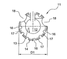
図1に示す帯状片から形成されたコイル状のアンカ素子11は、シャフトのための貫通開口12を有し、360°を超える角度範囲にわたって延在し、本実施例では貫通開口12の周りを3回分、すなわち、1080°の角度範囲にわたって延在している。帯状片によって形成されたアンカ素子11の延在長さは、必ずしも360°の整数倍である必要はない。例えば帯状片は480°の角度範囲にわたって延在し、したがって、貫通開口12を1.3回分だけ周回している。アンカ素子11は、例えば長さをカットすることにより、現場の状況または異なる荷重状態に簡単に適合させることができる。
A coil-
アンカ素子11は、貫通開口12に向いた内縁13と、貫通開口12から離反した外縁14とを有している。アンカ素子11は、金属、有利には鋼薄板により打抜き/曲げ加工方法で作製されている。
The
図2に示す帯状のアンカ素子31は、互いに隣接する周方向部分36または37で互いに結合された複数の環状ディスク型素子片35を有している。この帯状のアンカ素子31は、360°を超える角度範囲にわたって延在し、本実施例では、貫通開口32の周りを7回分、すなわち、2050°の角度範囲にわたって延在している。アンカ素子31のそれぞれの環状ディスク型素子部分35は、貫通開口32に向いた内縁33と、貫通開口32から離反した外縁34とを有している。アンカ素子31は、有利にはプラスチックにより、有利には繊維強化プラスチックにより射出成形法で作製されている。個々の環状ディスク型素子部分35は、例えばはんだ付け箇所または溶接箇所などの別個の結合点で、互いに結合されアンカ素子31をなしている。
The band-shaped
次に図3から図5に基づき、種々異なった形状付与部の種類について説明する。図1、図2、図8および図9に示したアンカ素子11,31,81および101は、これらの構造の全てを有していてもよいし、または少なくとも部分的に有していてもよい。
Next, based on FIGS. 3 to 5, various types of shape imparting portions will be described. The
図3および図4では、帯状のアンカ素子11の外縁14に半径方向外向きに開口した切欠き16の形の形状付与部が設けられており、これらの切欠き16は、容易に変位可能な複数のフィンを形成している。大部分の切欠き16の間には、外縁14を起点として半径方向内向きの複数のスリット17が設けられている。これらのスリット17は、アンカ素子11の自由な縁部を部分的に拡開し、これにより、アンカ素子11をドリル孔壁に簡単に適合させることができる。帯状のアンカ素子11の外縁14には、硬化可能材料のためのさらなる2つの貫通開口18が設けられている。アンカ素子11は外径D1を有している。
In FIGS. 3 and 4, a shape imparting portion in the form of a
アンカ素子11は、ディスク平面に波状形状付与部を有している(図4)。アンカ素子11は、帯状片平面において異なる厚さCおよびEを有し、厚さは貫通開口12を起点として半径方向外方に向けて増大する。
The
図5では、帯状のアンカ素子31の外縁34に、半径方向外向きに開口した38の形の形状付与部が設けられており、これらの切欠きは、容易に変位可能な複数のフィンを形成している。帯状のアンカ素子31の内縁33には同様に形状付与部が付加的に設けられており、この形状付与部は、周方向に互いに離間され、半径方向内向きに開口した切欠き39により形成されている。アンカ素子31は外径D2を有している。
In FIG. 5, the
図6には、硬化可能材料43によってドリル孔42の内部に固定装置50を固定するための固定システム41が示されている。
FIG. 6 shows a fixing
固定装置50は、外形付与部53として雄ねじ山が設けられたシャフト52を備える固定素子51と、前述のように構成され、互いに離間された3つのアンカ素子11および31とを有している。アンカ素子31に対して間隔をおいて、シャフト52の打込み方向端部56に帯状のアンカ素子11が設けられている。
The fixing
固定装置50を打ち込むためには、構成部分44の内部にまずドリルによってドリル孔42が形成され、この場合に、形成されるドリル孔42の公称径Nはアンカ素子11の外径D1よりも小さく、かつアンカ素子31の外径D1よりも小さく選択されている。ドリル孔深さTは、一方では固定素子51のために必要な係止長さにより、かつ他方ではドリル孔42内の穿孔屑を収容するために固定素子51の前方に必要とされる空間により決定される。
In order to drive the fixing
次いで、ドリル孔42には所定量の硬化可能材料43が充填され、固定装置50が、固定素子51のシャフト52の打込み方向端部56から先にドリル孔42に手動または機械的に導入される。この場合、固定素子51のシャフト52に配置されたアンカ素子11および31はドリル孔壁に沿って滑動し、これにより、ドリル孔壁に付着している穿孔屑の大部分はそこから除去され、硬化可能材料43に混合されるか、またはドリル孔底部に向けて移動する。アンカ素子11および31は、例えば固定素子51のシャフト52に押し込まれるか、またはシャフト52にねじ込まれる。固定装置50の導入時に、硬化可能材料43は、貫通開口18および切欠き16もしくは切欠き38および39を通ってンカ素子11および31を貫流し、これらを取り囲み、これにより、硬化可能材料43、および場合によってはこの硬化可能材料43の内部に位置する穿孔屑が一様に混合され、アンカ素子11および31は材料45の硬化後にこの材料内にほぼ完全に埋設される。
The
代替的には、まず固定装置50がドリル孔42に導入され、次いで硬化可能材料43が挿入される。さらに代替には、まず所定の少量の硬化可能材料43がドリル孔42の内部に挿入され、固定装置50がドリル孔42の内部に導入され、次いでドリル孔42のまだ残されている空間にさらなる量の硬化可能材料43が充填される。
Alternatively, the
さらに固定素子51のシャフト52に射出孔が設けられていてもよい。この射出孔を通って、固定素子51の導入後または導入中に硬化可能材料43をドリル孔42に挿入可能である。
Furthermore, an injection hole may be provided in the
既に硬化可能材料43の硬化前に、固定装置50、ひいては固定素子51は制限された荷重レベルで負荷可能である。なぜならば、アンカ素子11および31は固定素子51をドリル孔42の内部に機械的に係止させるからである。硬化可能材料43の硬化後には、打ち込まれた固定装置50は最大許容荷重レベルまで負荷可能である。
Prior to curing of the
アンカ素子11の外縁14またはアンカ素子31の外縁34は、さらに少なくとも部分的にドリル孔壁内に係合するので、十分な接触面が提供される、裂断されたコンクリートにおいても固定装置41を使用することができる。
The
異なるアンカ素子11および31の代わりに複数の同種の固定素子11または31をシャフトに設けてもよい。打ち込まれる固定素子に対する要求に関連して、固定素子51のシャフトにアンカ素子を1つのみ設けてもよい。
Instead of the
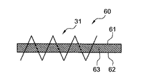
図7に示す固定装置60は、外形付与部63としてねじ山を有するシャフト62を備える固定素子61に帯状のアンカ素子31を設けており、このアンカ素子31は、互いに隣接した周方向部分で互いに結合された複数の環状ディスク型素子部分35により形成されている。
The fixing
図8に示す固定装置70はアンカ素子81として帯状片を有しており、この帯状片は、360°を超える角度範囲にわたって貫通開口82の周りに延在している。帯状片は、非円形の外形および非円形の内形を有している。これらの外形および内形は、それぞれ360°の角度範囲にわたって少なくとも2つの変曲点83または84を有している。帯状のアンカ素子81の隣接する2つの巻き部の変曲点83または84は、本実施例では互いに対して12.5°の角度差(A)をもって配置されている。変曲点83もしくは84は、それぞれ丸く形成されており、帯状のアンカ素子81の部分はそれぞれアーチ状に延在している。帯状のアンカ素子81とシャフト72の外面との間の空間ならびにドリル孔42の壁とアンカ素子81との間の空間は、硬化可能材料のための貫通開口88を形成している。アンカ素子81の最大外形D3は、固定装置70が挿入されるドリル孔の公称径よりも大きく形成されている。
The fixing
図9に示す実施形態では、固定装置70は、外形付与部として雄ねじ山を設けたシャフト92を有する固定素子91と、コイル状に形成された帯状のアンカ素子101とを備えている。この帯状のアンカ素子101の外縁104は、固定素子91の長手方向軸線94に対して鋭角をなしてシャフト92の外面から突出し、シャフト92の端部95の方向に拡開された複数の円錐を形成している。アンカ素子101の外縁104は、隣接する内縁103とのオーバラップUを有している。アンカ素子101が円錐状に構成されていることにより、この固定装置90は有利には後から拡開する特性を有しており、これにより、裂断した基盤、例えばコンクリートにも適している。
In the embodiment shown in FIG. 9, the fixing
11,31,81,101 アンカ素子
12,32,82 貫通開口
13,33 内縁
14,34,104 外縁
16 切欠き
17 スリット
18,88 貫通開口
35 環状ディスク型素子部分
36,37 周方向部分
41 固定システム
42 ドリル孔
43 硬化可能材料
44 構成部分
50,60,70,90 固定装置
51,61,71,91 固定素子
52,62,72,92 シャフト
53,63 外形付与部
83,84 変曲点
92 シャフト
95 端部
D1,D2,D3 外径
N 公称径
U オーバラップ
11, 31, 81, 101
Claims (13)
360°を超える角度範囲にわたって前記貫通開口(12;32;82)の周りに延在する帯状片を備えることを特徴とするアンカ素子。 For the shaft (52; 62; 72; 92) arranged on the shaft (52; 62; 72; 92) provided with the contouring part (53; 63) in the fixing element (51; 61; 71; 91) In an anchor element having through-openings (12; 32; 82),
An anchor element comprising a strip extending around the through-opening (12; 32; 82) over an angular range exceeding 360 °.
前記帯状片がコイル状に形成されているアンカ素子。 The anchor element according to claim 1,
An anchor element in which the strip is formed in a coil shape.
前記帯状片が、360°の角度範囲にわたって少なくとも2つの変曲点(83)を有する非円形の外形を有しているアンカ素子。 The anchor element according to claim 1 or 2,
An anchor element, wherein the strip has a non-circular profile with at least two inflection points (83) over an angular range of 360 °.
前記帯状片が、360°の角度範囲にわたって少なくとも2つの変曲点(84)を有する非円形の内形を有しているアンカ素子。 The anchor element according to claim 3,
An anchor element, wherein the strip has a non-circular inner shape with at least two inflection points (84) over an angular range of 360 °.
前記帯状片の隣接する2つの前記変曲点(83;84)が、互いに対して所定の角度差をもって配置されているアンカ素子。 The anchor element according to claim 3 or 4,
An anchor element in which two adjacent inflection points (83; 84) of the strip are arranged with a predetermined angular difference with respect to each other.
前記帯状片が、互いに隣接した周方向部分(36,37)で互いに結合された複数の環状ディスク型素子部分(35)を有しているアンカ素子。 The anchor element according to claim 1,
An anchor element in which the strip has a plurality of annular disk-shaped element portions (35) joined together at circumferential portions (36, 37) adjacent to each other.
前記帯状片の半径方向外縁(14;34)および/または半径方向内縁(13;33)に形状付与部が設けられているアンカ素子。 In the anchor element according to any one of claims 1 to 6,
An anchor element in which a shape imparting portion is provided on a radially outer edge (14; 34) and / or a radially inner edge (13; 33) of the strip.
前記帯状片が、その延在長さに沿って波状の構成を有しているアンカ素子。 The anchor element according to any one of claims 1 to 7,
An anchor element in which the strip has a wave-like configuration along its extending length.
前記帯状片に、硬化可能材料(43)のための少なくとも1つの貫通開口(18)が設けられているアンカ素子。 In the anchor element according to any one of claims 1 to 8,
An anchor element, wherein the strip is provided with at least one through-opening (18) for a curable material (43).
外形付与部(53;63)を設けたシャフト(52;62;72;91)を有する固定素子(51;61;71;91)と、請求項1から9までのいずれか一項に記載のアンカ素子(11;31;81;101)のうち少なくとも1つとを備えることを特徴とする固定装置。 In a fixing device which can be locked inside the drill hole (42) by a curable material (43),
10. A fixing element (51; 61; 71; 91) having a shaft (52; 62; 72; 91) provided with an outer shape imparting part (53; 63), and according to any one of claims 1-9. A fixing device comprising at least one of the anchor elements (11; 31; 81; 101).
複数の前記アンカ素子(11;31)が、互いに間隔をおいて1本の前記シャフト(52)に設けられている固定装置。 The fixing device according to claim 10, wherein
A fixing device in which a plurality of the anchor elements (11; 31) are provided on one shaft (52) at intervals.
種々異なった構成の前記アンカ素子(11,31)が、1本の前記シャフト(52)に設けられている固定装置。 The fixing device according to claim 10 or 11,
A fixing device in which the anchor elements (11, 31) having different configurations are provided on one shaft (52).
固定素子(51;61;71;91)に配置された少なくとも1つのアンカ素子(11;31;81;101)が、前記ドリル孔(42)の公称径(N)よりも大きい最大外径(D1,D2,D3)を有していることを特徴とする固定システム。 Locking device (50; 60; 70; 90) according to any one of claims 10 to 12 locked by a curable material (43) into a drill hole (42) having a nominal diameter (N) In the fixing system (41) for
A maximum outer diameter (at least one anchor element (11; 31; 81; 101) arranged on the fixing element (51; 61; 71; 91) is larger than the nominal diameter (N) of the drill hole (42). D1, D2, D3).
Applications Claiming Priority (2)
| Application Number | Priority Date | Filing Date | Title |
|---|---|---|---|
| DE102008040694A DE102008040694A1 (en) | 2008-07-24 | 2008-07-24 | anchoring element |
| DE102008040694.5 | 2008-07-24 |
Publications (2)
| Publication Number | Publication Date |
|---|---|
| JP2010032048A true JP2010032048A (en) | 2010-02-12 |
| JP5517518B2 JP5517518B2 (en) | 2014-06-11 |
Family
ID=41056993
Family Applications (1)
| Application Number | Title | Priority Date | Filing Date |
|---|---|---|---|
| JP2009171551A Active JP5517518B2 (en) | 2008-07-24 | 2009-07-22 | Anchor element |
Country Status (6)
| Country | Link |
|---|---|
| US (1) | US20100021260A1 (en) |
| EP (1) | EP2148100B1 (en) |
| JP (1) | JP5517518B2 (en) |
| CA (1) | CA2674017A1 (en) |
| DE (1) | DE102008040694A1 (en) |
| ES (1) | ES2393835T3 (en) |
Cited By (2)
| Publication number | Priority date | Publication date | Assignee | Title |
|---|---|---|---|---|
| JP2018080495A (en) * | 2016-11-16 | 2018-05-24 | 株式会社ティ・エス・プランニング | Anchor fixture |
| JP6351892B1 (en) * | 2018-02-09 | 2018-07-04 | 株式会社ティ・エス・プランニング | Anchor fixing jig |
Families Citing this family (1)
| Publication number | Priority date | Publication date | Assignee | Title |
|---|---|---|---|---|
| DE202018100768U1 (en) * | 2018-02-13 | 2018-04-03 | PreConTech International GmbH | Anchorage for precast concrete elements |
Citations (3)
| Publication number | Priority date | Publication date | Assignee | Title |
|---|---|---|---|---|
| US1688087A (en) * | 1927-07-12 | 1928-10-16 | Richard A Mirzan | Means for anchoring bolts |
| JPH0674226A (en) * | 1991-12-04 | 1994-03-15 | Katsumi Ikeda | Mechanical element for fastening and joining thereof |
| JP2001214538A (en) * | 2000-02-02 | 2001-08-10 | Atsushi Ota | Anchor for concrete |
Family Cites Families (14)
| Publication number | Priority date | Publication date | Assignee | Title |
|---|---|---|---|---|
| US1468074A (en) * | 1920-11-15 | 1923-09-18 | Ralph S Peirce | Anchoring device |
| US1966520A (en) * | 1930-09-10 | 1934-07-17 | Rayner John | Art of threaded fastening |
| US2755699A (en) * | 1953-07-16 | 1956-07-24 | Heli Coil Corp | Wire coil screw thread insert with grip end having an angular configuration |
| US3308229A (en) * | 1965-03-12 | 1967-03-07 | Buchanan Electrical Prod Corp | Electric wire connector assembly |
| US3716608A (en) * | 1971-02-12 | 1973-02-13 | Neumann G Terrasan Erzeugnisse | Method for restoring railway ties |
| US3967525A (en) * | 1974-01-02 | 1976-07-06 | Wej-It Expansion Products, Inc. | Spring action expansion bolt |
| US4536115A (en) * | 1982-06-30 | 1985-08-20 | Helderman J Frank | Anchor apparatus for insertion into a pre-formed hole |
| US5366328A (en) * | 1993-06-07 | 1994-11-22 | Helderman J F | Assembly for inserting an attachment coil in concrete |
| US6494659B1 (en) * | 2000-02-04 | 2002-12-17 | Emhart Llc | Anti-galling fastener inserts |
| US6461092B2 (en) * | 2001-02-22 | 2002-10-08 | Shao-Chien Tseng | Anti-dead locking, anti-vibration and loosening-proof bolt/nut structure |
| US6726422B2 (en) * | 2001-11-02 | 2004-04-27 | Newfrey Llc | Helically coiled titanium wire fastener inserts |
| DE10220116A1 (en) * | 2002-05-06 | 2003-11-20 | Hilti Ag | anchoring element |
| US6835036B2 (en) * | 2003-03-07 | 2004-12-28 | Illinois Tool Works Inc. | Concrete anchor |
| US8556558B1 (en) * | 2006-07-31 | 2013-10-15 | Christopher M. Hunt | Fastener for cementitious materials |
-
2008
- 2008-07-24 DE DE102008040694A patent/DE102008040694A1/en not_active Withdrawn
-
2009
- 2009-07-09 ES ES09165004T patent/ES2393835T3/en active Active
- 2009-07-09 EP EP09165004A patent/EP2148100B1/en not_active Not-in-force
- 2009-07-22 JP JP2009171551A patent/JP5517518B2/en active Active
- 2009-07-23 US US12/460,885 patent/US20100021260A1/en not_active Abandoned
- 2009-07-24 CA CA2674017A patent/CA2674017A1/en not_active Abandoned
Patent Citations (3)
| Publication number | Priority date | Publication date | Assignee | Title |
|---|---|---|---|---|
| US1688087A (en) * | 1927-07-12 | 1928-10-16 | Richard A Mirzan | Means for anchoring bolts |
| JPH0674226A (en) * | 1991-12-04 | 1994-03-15 | Katsumi Ikeda | Mechanical element for fastening and joining thereof |
| JP2001214538A (en) * | 2000-02-02 | 2001-08-10 | Atsushi Ota | Anchor for concrete |
Cited By (2)
| Publication number | Priority date | Publication date | Assignee | Title |
|---|---|---|---|---|
| JP2018080495A (en) * | 2016-11-16 | 2018-05-24 | 株式会社ティ・エス・プランニング | Anchor fixture |
| JP6351892B1 (en) * | 2018-02-09 | 2018-07-04 | 株式会社ティ・エス・プランニング | Anchor fixing jig |
Also Published As
| Publication number | Publication date |
|---|---|
| ES2393835T3 (en) | 2012-12-28 |
| EP2148100A1 (en) | 2010-01-27 |
| JP5517518B2 (en) | 2014-06-11 |
| DE102008040694A1 (en) | 2010-01-28 |
| EP2148100B1 (en) | 2012-10-17 |
| CA2674017A1 (en) | 2010-01-24 |
| US20100021260A1 (en) | 2010-01-28 |
Similar Documents
| Publication | Publication Date | Title |
|---|---|---|
| EP3115627B1 (en) | Expansion anchor | |
| WO2006012928A1 (en) | Expansion rivet | |
| JP5517518B2 (en) | Anchor element | |
| JP5464933B2 (en) | Washer-like anchor element | |
| EP3227510A1 (en) | Sealing plug for closing an anchor hole in a concrete wall | |
| JP2010031639A (en) | Anchor element | |
| KR20060037457A (en) | Fixing device for producing an anchorage in plates especially consisting of glass | |
| US9551370B2 (en) | Anchoring sleeve | |
| JP2009281590A (en) | Fastening element | |
| KR20120094036A (en) | Anchor sleeve | |
| JP2007046388A (en) | Installation method for bolt with enlarged end | |
| JP6768659B2 (en) | Improvement of joining equipment | |
| WO2004026158A1 (en) | Fixation device | |
| KR20160127961A (en) | Anchor bolt and construction method thereof | |
| US20230204061A1 (en) | Fastener hole restoration device | |
| JP2686884B2 (en) | Nail holding member | |
| KR102216446B1 (en) | Seismic resistant anchor for outer wall of building and construction method thereof | |
| KR200485838Y1 (en) | Anchor Bolt for Fixing Wall | |
| JP5134201B2 (en) | Expandable anchor plug and construction method using the same | |
| JP2006256213A (en) | Lining method and lining material | |
| DE202012002026U1 (en) | Adhesive anchor and building part | |
| DE202019004747U1 (en) | Adjusting dowels and assembly kit | |
| SE534165C2 (en) | Mounting bolt clips | |
| JPH11127908A (en) | Spike for shoes and shoe bottom structure using same spike | |
| DE102016106251A1 (en) | Anchor rod and mounting arrangement |
Legal Events
| Date | Code | Title | Description |
|---|---|---|---|
| A621 | Written request for application examination |
Free format text: JAPANESE INTERMEDIATE CODE: A621 Effective date: 20120711 |
|
| A977 | Report on retrieval |
Free format text: JAPANESE INTERMEDIATE CODE: A971007 Effective date: 20130621 |
|
| A131 | Notification of reasons for refusal |
Free format text: JAPANESE INTERMEDIATE CODE: A131 Effective date: 20130702 |
|
| A521 | Request for written amendment filed |
Free format text: JAPANESE INTERMEDIATE CODE: A523 Effective date: 20131001 |
|
| TRDD | Decision of grant or rejection written | ||
| A01 | Written decision to grant a patent or to grant a registration (utility model) |
Free format text: JAPANESE INTERMEDIATE CODE: A01 Effective date: 20140304 |
|
| A61 | First payment of annual fees (during grant procedure) |
Free format text: JAPANESE INTERMEDIATE CODE: A61 Effective date: 20140401 |
|
| R150 | Certificate of patent or registration of utility model |
Ref document number: 5517518 Country of ref document: JP Free format text: JAPANESE INTERMEDIATE CODE: R150 |
|
| R250 | Receipt of annual fees |
Free format text: JAPANESE INTERMEDIATE CODE: R250 |
|
| R250 | Receipt of annual fees |
Free format text: JAPANESE INTERMEDIATE CODE: R250 |
|
| R250 | Receipt of annual fees |
Free format text: JAPANESE INTERMEDIATE CODE: R250 |