JP2010030465A - Vehicle rear part structure - Google Patents
Vehicle rear part structure Download PDFInfo
- Publication number
- JP2010030465A JP2010030465A JP2008195268A JP2008195268A JP2010030465A JP 2010030465 A JP2010030465 A JP 2010030465A JP 2008195268 A JP2008195268 A JP 2008195268A JP 2008195268 A JP2008195268 A JP 2008195268A JP 2010030465 A JP2010030465 A JP 2010030465A
- Authority
- JP
- Japan
- Prior art keywords
- back door
- vehicle
- spoiler
- surface portion
- roof
- Prior art date
- Legal status (The legal status is an assumption and is not a legal conclusion. Google has not performed a legal analysis and makes no representation as to the accuracy of the status listed.)
- Granted
Links
Images


Landscapes
- Body Structure For Vehicles (AREA)
Abstract
Description
本発明は、車両の後部構造に関するものである。 The present invention relates to a rear structure of a vehicle.
車両の後部を車両前後方向後方に向かうにつれて下方に傾斜させると、空力特性が改善することが一般に知られている。しかし、車のデザインによっては、見栄えが悪化する場合がある。このような問題を解決するため、特許文献1では、ルーフからリアゲートに掛けて、車両前後方向に連続する凹部を車幅方向中央部のみに形成することにより、車両の側面視では尻下がりとならないデザインとしながら空力特性を向上させている。
しかしながら、バックドア本体は、一般に金属製であり、プレス加工等による凹部の形成がそもそも容易ではない。空力特性改善のためには、凹部に一定の長さや深さが要求され、バックドア上面の加工性を更に悪化させている。 However, the back door body is generally made of metal, and it is not easy to form the recesses by pressing or the like. In order to improve aerodynamic characteristics, a certain length and depth are required for the recess, which further deteriorates the workability of the back door upper surface.
従って、本発明の目的は、スポイラの一部に凹部を形成し、バックドア上面の凹部領域を小さくすることによりバックドアの加工性を確保しながら、空力特性を向上することにある。 Accordingly, an object of the present invention is to improve the aerodynamic characteristics while ensuring the workability of the back door by forming a recess in a part of the spoiler and reducing the recess area on the upper surface of the back door.
上記課題を解決するため、本発明においては、車体の後部に設けた開口部を開閉するバックドアと、前記バックドアに設けられ、車幅方向に延設されたスポイラと、を備えた車両の後部構造において、前記バックドアが、前記車体のルーフ部上面と略連続するバックドア上面部を有し、前記スポイラが、前記バックドア上面部と略連続するスポイラ上面部を有し、車幅方向中央部において、前記ルーフ部上面、前記バックドア上面部及び前記スポイラ上面部に渡って車両前後方向に延設された凹部を有することを特徴とする車両の後部構造が提供される。 In order to solve the above-described problem, in the present invention, a vehicle having a back door that opens and closes an opening provided in a rear portion of a vehicle body, and a spoiler provided in the back door and extending in the vehicle width direction. In the rear structure, the back door has a back door upper surface portion that is substantially continuous with the roof portion upper surface of the vehicle body, and the spoiler has a spoiler upper surface portion that is substantially continuous with the back door upper surface portion. There is provided a rear structure of a vehicle having a concave portion extending in the vehicle front-rear direction over the roof portion upper surface, the back door upper surface portion, and the spoiler upper surface portion at a central portion.
本発明によれば、前記スポイラの一部である前記スポイラ上面部に前記凹部を形成し、前記バックドア上面部の前記凹部領域を小さくしたため、前記バックドアの加工性を確保しながら、空力特性を向上させることができる。 According to the present invention, the recess is formed in the upper surface portion of the spoiler that is a part of the spoiler, and the recess region of the upper surface portion of the back door is reduced, so that the aerodynamic characteristic is ensured while ensuring the workability of the back door. Can be improved.
また、本発明においては、前記バックドア上面部を含む前記バックドア本体が金属製であり、前記スポイラが樹脂製である構成であってもよい。この構成によれば、前記スポイラの加工性を悪化させることを抑制しながら、前記バックドア本体の加工性を向上することができる。 In the present invention, the back door main body including the back door upper surface part may be made of metal, and the spoiler may be made of resin. According to this configuration, it is possible to improve the workability of the back door body while suppressing deterioration of the workability of the spoiler.
前記凹部は、車両前後方向後方に向かうに従って深さが深い構成であってもよい。この構成によれば、空力特性を更に向上することができる。 The recess may have a deeper depth as it goes rearward in the vehicle front-rear direction. According to this configuration, the aerodynamic characteristics can be further improved.
また、本発明においては、前記バックドアが、前記バックドア上面部と連続し、車両後方下方に傾斜した後面部を有し、前記スポイラが、前記後面部から離間して車両後方に突出しており、前記スポイラ上面部の前記凹部を、前記スポイラ上面部の車両前後方向全域に渡って形成した構成であってもよい。この構成によれば、前記スポイラが前記後面部から離間して車両後方に突出し、前記凹部を前記スポイラ上面部の車両前後方向全域に渡って形成したため、前記凹部を通過する走行風を前記後面部に付着させることなく、車両後方に効率よく通過させることができる。 Further, in the present invention, the back door has a rear surface portion that is continuous with the upper surface portion of the back door and inclined downward in the rear of the vehicle, and the spoiler projects away from the rear surface portion to the rear of the vehicle. In addition, the concave portion of the upper surface portion of the spoiler may be formed over the entire vehicle front-rear direction of the upper surface portion of the spoiler. According to this configuration, the spoiler projects away from the rear surface portion and protrudes toward the rear of the vehicle, and the concave portion is formed over the entire area in the vehicle front-rear direction of the upper surface portion of the spoiler. Without being attached to the vehicle, it can be passed through the vehicle efficiently.
本発明によれば、スポイラの一部に凹部を形成し、バックドア上面の凹部領域を小さくすることによりバックドアの加工性を確保しながら、空力特性を向上することができる。 ADVANTAGE OF THE INVENTION According to this invention, a recessed part is formed in a part of spoiler and the aerodynamic characteristic can be improved, ensuring the workability of a back door by making the recessed part area | region of a back door upper surface small.
以下に、本発明の実施の形態について添付図面を参照して詳細に説明する。なお、以下に説明する実施の形態は、本発明の実現手段としての一例であり、本発明は、その趣旨を逸脱しない範囲で以下の実施形態を修正又は変形したものに適用可能である。 Hereinafter, embodiments of the present invention will be described in detail with reference to the accompanying drawings. The embodiment described below is an example as means for realizing the present invention, and the present invention can be applied to a modified or modified embodiment described below without departing from the spirit of the present invention.
[車両全体の構成について]
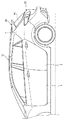
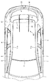
図1は、本発明の一実施形態に係る車両の側面図であり、図2は、一実施形態に係る車両の上面図である。また、図3は、車両の後部構造を示す斜視図であり、図4は、車両の後部構造を示す背面図である。
[About overall vehicle configuration]
FIG. 1 is a side view of a vehicle according to an embodiment of the present invention, and FIG. 2 is a top view of the vehicle according to an embodiment. 3 is a perspective view showing the rear structure of the vehicle, and FIG. 4 is a rear view showing the rear structure of the vehicle.
この車両は、本実施形態では、フロントドア1、2、リアドア3、4及びバックドア20を有する5ドアのハッチバックタイプの車両である。
In this embodiment, this vehicle is a five-door hatchback type vehicle having
車両は、車両前後方向に延びて車室の上面となるルーフ部上面11を形成するルーフ部10と、車体の後部に設けた後方開口部Sを開閉するバックドア20と、バックドア20に設けられ、車幅方向に延設されたスポイラ30とを備える。
The vehicle includes a
ルーフ部10は、薄板鋼板等の金属材料をプレス加工することにより形成される。また、ルーフ部10は、ルーフ部上面11の車幅方向側端部11a、11bのそれぞれに設けられたフランジを有し、このフランジが左右の車体側部(例えば、サイドボディアウタパネル7、8)の上下方向上方側に設けられたフランジと溶接等で接合される。これにより、ルーフ部10は、車体側部及び車体下部と共に後方開口部Sを形成する。
The
後方開口部Sには、跳ね上げ式のバックドア20が配設される(図5参照)。バックドア20は、ルーフ部上面11と略連続する平面を形成するバックドア上面部21を有する。なお、バックドア20は、車幅方向に延びる回転軸を有する跳ね上げ式のドアに限らず、上下方向に延びる回転軸を有する、例えば観音式のドア等であってもよい。
In the rear opening S, a flip-
スポイラ30は、バックドア20のウインドウW1上部に固定され、バックドア上面部21と略連続する平面を形成するスポイラ上面部31を有する。
The
ルーフ部上面11、バックドア上面部21及びスポイラ上面部31には、車幅方向中央部において、車両の前後方向に略連続して延びる凹部40が形成されている。なお、ルーフ部上面11に設けられた凹部を第1凹部41、バックドア上面部21に設けられた凹部を第2凹部42、スポイラ上面部31に設けられた凹部を第3凹部43と呼ぶこととする。
The roof portion
[車両の後部構造の詳細について]
図5は、車両の後部構造の分解斜視図である。また、図6において、(a)は図5のA−A線に沿った断面図であり、(b)は図5のB−B線に沿った断面図であり、(c)は図5のC−C線に沿った断面図である。
[Details of rear structure of vehicle]
FIG. 5 is an exploded perspective view of the rear structure of the vehicle. 6A is a cross-sectional view taken along the line AA in FIG. 5, FIG. 6B is a cross-sectional view taken along the line BB in FIG. 5, and FIG. It is sectional drawing along CC line.
ルーフ部10は、ルーフ部上面11の車両前後方向後方側の端部11cにおいて、上下方向下方に折り曲げて形成された縦壁部12と、縦壁部12を車両前後方向後方に折り曲げて形成され、ドアヒンジH1、H2を取り付けるための座面部13と、座面部13の車両前後方向後方に設けられ、車室内への雨水の浸入を防止する雨樋部14と、雨樋部14の車両前後方向後方端部14aに設けられ、バックドア20とルーフ部10との間の密閉性を確保するシール部15とが設けられる。
The
縦壁部12は、バックドア上面部21の車両前後方向前端部21a(すなわち、ヘム部)との干渉を防止するために、例えば、カム構造の金型を用いて90度以上に折り曲げて形成される。雨樋部14は、座面部13の車両前後方向後端部13aを、例えば、断面U字形状に折り曲げることにより形成される。シール部15としては、例えば、ゴムやウレタン等の弾性部材を用いることができる。
The
バックドア20は、バックドア本体がアウタパネル22とインナパネル23とで形成され、ウインドウW1上方において、インナパネル23にボルト等で固定されたドアヒンジH1、H2を座面部13にボルト等で固定することにより、車体に対して回動可能に取り付けられる。ドアヒンジH1、H2は、それぞれが凹部40の車幅方向外側に取り付けられる。
The
アウタパネル22及びインナパネル23は、薄板鋼板等の金属材料をプレス加工することにより成形され、バックドア20は、これらをヘム加工することにより成形される。従って、ルーフ部上面11と略連続するバックドア上面部21は、アウタパネル22の外面によって形成されることとなる。ウインドウW1上部におけるアウタパネル22には、スタッドボルト32及びファスナ33を取り付けるための孔部24が複数設けられている。また、バックドア20は、バックドア上面部21と連続し、車両後方下方に傾斜した後面部25を有する。
The
スポイラ30は、例えば、ポリプロピレン等の樹脂材料をブロー加工することにより成形される。スポイラ30には、スタッドボルト32がブロー成形時に埋め込まれている。スポイラ30は、ファスナ33を孔部24に嵌め込み、また、バックドア20のアウタパネル22の内壁側から、スタッドボルト32をナットで締結することにより、バックドア20のウインドウW1上部に固定される。なお、バックドア20のインナパネル23には、スタッドボルト32をナットで締結する際に用いられる図示しない作業孔が設けられており、この作業孔は作業後にキャップで閉塞される。スポイラ30は、バックドア20の後面部25から離間して車両後方に突出している。
The
このように、スポイラ30をファスナ33からなる結合手段と、スタッドボルト32及びナットからなる締結手段との組み合わせによって行うことで、スポイラ30の取付作業を容易に行いながら、スポイラ30を強固に固定することが可能となる。
Thus, the
凹部40は、ルーフ部上面11、バックドア上面部21及びスポイラ上面部31における車幅方向中央に略連続して、車両前後方向後方下方に一定の傾斜角度で傾斜し(すなわち、後方に向かうにつれて凹部40の底面位置が低くなるように傾斜し)、更に、車両の前後方向後方に向かうに従って深さが深く形成される。凹部40は、好ましくは傾斜角度がおよそ10度となるように形成される。
The
第1凹部41は、本実施形態では、ルーフ部上面11の車両前後方向中央よりも後方に形成される。なお、第1凹部41の前端の位置は、凹部40の長さや傾斜角度等によって任意に設定することができる。バックドア上面部21に形成される第2凹部42は、バックドア上面部21の車両前後方向前端部21aと後端部21bとの間の全域に渡って形成され、双方の端部21a、21bが開口端部を形成する。同様に、第3凹部43は、スポイラ上面部31の車両前後方向前端部31aと後端部31bとの間の全域に渡って形成され、双方の端部31a、31bが開口端部を形成する。
In the present embodiment, the
これにより、第1乃至第3凹部41、42、43が車両前後方向に略連続し、第1凹部41の前方側の開口端部から走行風を取り入れ、第3凹部43の後方側の開口端部から走行風を後方へ逃がすことが可能となる。また、スポイラ30がバックドア20の後面部25から離間して車両後方に突出し、前記第3凹部43がスポイラ上面部31の全域に渡って形成されることにより、凹部40を吹き降ろす走行風がバックドア20の後面部25に付着することを防止することができる。これにより、走行風を車体近傍でよどませることなく、効率良く車体後方に通過させることができるため、空力特性を向上することができる。
As a result, the first to
以上述べた通り、本実施形態によれば、スポイラ30の一部であるスポイラ上面部31に凹部40を形成し、バックドア上面部21の凹部領域を小さくしたため、バックドア20の加工性を確保しながら、空力特性を向上させることができる。また、スポイラ30に樹脂製スポイラを採用したため、スポイラ30の加工性を悪化させることを抑制しながら、金属製のバックドア20の加工性を向上することができる。更に、車両前後方向後方に向かうにつれて深く形成したため、成形性の影響が少ないスポイラ30の成形深さを深くする一方でバックドア20の成形深さを浅くすることができる。
As described above, according to the present embodiment, the
なお、凹部40は、本実施形態では、一定の傾斜角度で傾斜することとしたが、車両前後方向後方に向かうにつれて傾斜角度が大きくなるように形成してもよい。この場合には、凹部40のうち、車両前後方向前方側に設けられる第1凹部41及び第2凹部42の傾斜角度をプレス加工の成形性を悪化させない程度の比較的小さな角度とし、車両前後方向後方側に設けられる第3凹部43の傾斜角度については、スポイラ30が樹脂のブロー加工により成形されるため、成形性を気にすることなく、大きな傾斜角度を設定することが可能である。
In this embodiment, the
S 後方開口部
10 ルーフ部
11 ルーフ部上面
20 バックドア
21 バックドア上面部
30 スポイラ
31 スポイラ上面部
40 凹部
S
Claims (4)
前記バックドアに設けられ、車幅方向に延設されたスポイラと、
を備えた車両の後部構造において、
前記バックドアが、前記車体のルーフ部上面と略連続するバックドア上面部を有し、
前記スポイラが、前記バックドア上面部と略連続するスポイラ上面部を有し、
車幅方向中央部において、前記ルーフ部上面、前記バックドア上面部及び前記スポイラ上面部に渡って車両前後方向に延設された凹部を有することを特徴とする車両の後部構造。 A back door that opens and closes an opening provided at the rear of the vehicle body;
A spoiler provided in the back door and extending in the vehicle width direction;
In the rear structure of the vehicle with
The back door has a back door top surface portion substantially continuous with the roof top surface of the vehicle body;
The spoiler has a spoiler upper surface portion substantially continuous with the back door upper surface portion;
A rear structure of a vehicle having a concave portion extending in a vehicle front-rear direction across the roof portion upper surface, the back door upper surface portion, and the spoiler upper surface portion at a vehicle width direction central portion.
前記スポイラが、前記後面部から離間して車両後方に突出しており、
前記スポイラ上面部の前記凹部を、前記スポイラ上面部の車両前後方向全域に渡って形成したことを特徴とする請求項1乃至3のいずれか1項に記載の車両の後部構造。 The back door is continuous with the back door upper surface portion, and has a rear surface portion inclined downward in the rear of the vehicle,
The spoiler protrudes rearward of the vehicle away from the rear surface portion;
The rear structure of the vehicle according to any one of claims 1 to 3, wherein the concave portion of the upper surface portion of the spoiler is formed over the entire region of the upper surface portion of the spoiler in the vehicle front-rear direction.
Priority Applications (1)
| Application Number | Priority Date | Filing Date | Title |
|---|---|---|---|
| JP2008195268A JP5262400B2 (en) | 2008-07-29 | 2008-07-29 | Rear structure of the vehicle |
Applications Claiming Priority (1)
| Application Number | Priority Date | Filing Date | Title |
|---|---|---|---|
| JP2008195268A JP5262400B2 (en) | 2008-07-29 | 2008-07-29 | Rear structure of the vehicle |
Publications (2)
| Publication Number | Publication Date |
|---|---|
| JP2010030465A true JP2010030465A (en) | 2010-02-12 |
| JP5262400B2 JP5262400B2 (en) | 2013-08-14 |
Family
ID=41735494
Family Applications (1)
| Application Number | Title | Priority Date | Filing Date |
|---|---|---|---|
| JP2008195268A Expired - Fee Related JP5262400B2 (en) | 2008-07-29 | 2008-07-29 | Rear structure of the vehicle |
Country Status (1)
| Country | Link |
|---|---|
| JP (1) | JP5262400B2 (en) |
Cited By (7)
| Publication number | Priority date | Publication date | Assignee | Title |
|---|---|---|---|---|
| DE102014114487A1 (en) | 2013-10-28 | 2015-04-30 | Suzuki Motor Corporation | Roof panel structure of a vehicle |
| JP2016078784A (en) * | 2014-10-22 | 2016-05-16 | 本田技研工業株式会社 | Vehicle body structure |
| JP6256587B1 (en) * | 2016-12-16 | 2018-01-10 | マツダ株式会社 | Car body rear structure |
| US20180056762A1 (en) * | 2016-08-30 | 2018-03-01 | Toyota Jidosha Kabushiki Kaisha | Vehicle door |
| US10065484B2 (en) | 2013-12-12 | 2018-09-04 | Toyota Jidosha Kabushiki Kaisha | Vehicle member attachment structure and rear spoiler attachment structure |
| EP3480041A1 (en) | 2017-11-07 | 2019-05-08 | Toyota Jidosha Kabushiki Kaisha | Vehicle rear structure |
| GB2581993A (en) * | 2019-03-06 | 2020-09-09 | Nissan Motor Mfg (Uk) Ltd | A spoiler arrangement for a motor vehicle |
Citations (5)
| Publication number | Priority date | Publication date | Assignee | Title |
|---|---|---|---|---|
| JPS62165183U (en) * | 1986-04-10 | 1987-10-20 | ||
| JP2002046658A (en) * | 2000-08-04 | 2002-02-12 | Daihatsu Motor Co Ltd | Rear spoiler for automobile |
| JP2007001521A (en) * | 2005-06-27 | 2007-01-11 | Mazda Motor Corp | Vehicle rear body structure |
| JP2007015416A (en) * | 2005-07-05 | 2007-01-25 | Mazda Motor Corp | Vehicle body rear part structure |
| JP2007015417A (en) * | 2005-07-05 | 2007-01-25 | Mazda Motor Corp | Vehicle body rear part structure for hatch back vehicle |
-
2008
- 2008-07-29 JP JP2008195268A patent/JP5262400B2/en not_active Expired - Fee Related
Patent Citations (5)
| Publication number | Priority date | Publication date | Assignee | Title |
|---|---|---|---|---|
| JPS62165183U (en) * | 1986-04-10 | 1987-10-20 | ||
| JP2002046658A (en) * | 2000-08-04 | 2002-02-12 | Daihatsu Motor Co Ltd | Rear spoiler for automobile |
| JP2007001521A (en) * | 2005-06-27 | 2007-01-11 | Mazda Motor Corp | Vehicle rear body structure |
| JP2007015416A (en) * | 2005-07-05 | 2007-01-25 | Mazda Motor Corp | Vehicle body rear part structure |
| JP2007015417A (en) * | 2005-07-05 | 2007-01-25 | Mazda Motor Corp | Vehicle body rear part structure for hatch back vehicle |
Cited By (13)
| Publication number | Priority date | Publication date | Assignee | Title |
|---|---|---|---|---|
| DE102014114487A1 (en) | 2013-10-28 | 2015-04-30 | Suzuki Motor Corporation | Roof panel structure of a vehicle |
| US10065484B2 (en) | 2013-12-12 | 2018-09-04 | Toyota Jidosha Kabushiki Kaisha | Vehicle member attachment structure and rear spoiler attachment structure |
| DE112014005668B4 (en) | 2013-12-12 | 2023-02-09 | Toyota Jidosha Kabushiki Kaisha | Vehicle member attachment structure and rear spoiler attachment structure |
| JP2016078784A (en) * | 2014-10-22 | 2016-05-16 | 本田技研工業株式会社 | Vehicle body structure |
| US20180056762A1 (en) * | 2016-08-30 | 2018-03-01 | Toyota Jidosha Kabushiki Kaisha | Vehicle door |
| DE102017117896A1 (en) | 2016-08-30 | 2018-03-01 | Toyota Jidosha Kabushiki Kaisha | vehicle flap |
| US10155433B2 (en) | 2016-08-30 | 2018-12-18 | Toyota Jidosha Kabushiki Kaisha | Vehicle door |
| JP2018095178A (en) * | 2016-12-16 | 2018-06-21 | マツダ株式会社 | Vehicle body rear part structure |
| JP6256587B1 (en) * | 2016-12-16 | 2018-01-10 | マツダ株式会社 | Car body rear structure |
| EP3480041A1 (en) | 2017-11-07 | 2019-05-08 | Toyota Jidosha Kabushiki Kaisha | Vehicle rear structure |
| US10583718B2 (en) | 2017-11-07 | 2020-03-10 | Toyota Jidosha Kabushiki Kaisha | Vehicle rear structure |
| GB2581993A (en) * | 2019-03-06 | 2020-09-09 | Nissan Motor Mfg (Uk) Ltd | A spoiler arrangement for a motor vehicle |
| GB2581993B (en) * | 2019-03-06 | 2021-03-24 | Nissan Motor Mfg Uk Ltd | A spoiler arrangement for a motor vehicle |
Also Published As
| Publication number | Publication date |
|---|---|
| JP5262400B2 (en) | 2013-08-14 |
Similar Documents
| Publication | Publication Date | Title |
|---|---|---|
| JP5262400B2 (en) | Rear structure of the vehicle | |
| US10889329B2 (en) | Vehicle side portion structure | |
| US8727420B2 (en) | Vehicle door structure | |
| JP6700979B2 (en) | Glass run for car door | |
| US10189504B2 (en) | Vehicle pillar structure | |
| US20190193535A1 (en) | Resin back door for vehicle | |
| CN101804826A (en) | Side vehicle-body structure of automotive vehicle | |
| US7938480B2 (en) | Vehicle body side structure | |
| US10525800B2 (en) | Vehicle door structure | |
| JP4489722B2 (en) | Vehicle side structure | |
| JP2010143453A (en) | Vehicle door structure | |
| US11479089B2 (en) | Side door structure of vehicle | |
| JP6256587B1 (en) | Car body rear structure | |
| JP4876923B2 (en) | Vehicle door structure | |
| JP2008179246A (en) | Vehicular garnish mounting structure | |
| JP2007098982A (en) | Chassis frame and body construction | |
| US10745063B2 (en) | Vehicle rear portion structure | |
| JP2017210048A (en) | Glass run for vehicle door | |
| JP4706549B2 (en) | Opening trim structure of sliding door vehicle | |
| JP6079794B2 (en) | Car door structure | |
| JP5746094B2 (en) | Door structure with weatherstrip | |
| JP5847794B2 (en) | Body structure with tailgate | |
| JP7103118B2 (en) | Vehicle side door structure | |
| US10953735B2 (en) | Penetrating wind prevention structure for vehicle | |
| JP2008013057A (en) | Lower structure of vehicle body |
Legal Events
| Date | Code | Title | Description |
|---|---|---|---|
| RD03 | Notification of appointment of power of attorney |
Free format text: JAPANESE INTERMEDIATE CODE: A7423 Effective date: 20101001 |
|
| RD04 | Notification of resignation of power of attorney |
Free format text: JAPANESE INTERMEDIATE CODE: A7424 Effective date: 20101001 |
|
| A621 | Written request for application examination |
Free format text: JAPANESE INTERMEDIATE CODE: A621 Effective date: 20110523 |
|
| A521 | Written amendment |
Free format text: JAPANESE INTERMEDIATE CODE: A523 Effective date: 20120522 |
|
| A977 | Report on retrieval |
Free format text: JAPANESE INTERMEDIATE CODE: A971007 Effective date: 20121130 |
|
| A131 | Notification of reasons for refusal |
Free format text: JAPANESE INTERMEDIATE CODE: A131 Effective date: 20121204 |
|
| A521 | Written amendment |
Free format text: JAPANESE INTERMEDIATE CODE: A523 Effective date: 20130131 |
|
| TRDD | Decision of grant or rejection written | ||
| A01 | Written decision to grant a patent or to grant a registration (utility model) |
Free format text: JAPANESE INTERMEDIATE CODE: A01 Effective date: 20130402 |
|
| A61 | First payment of annual fees (during grant procedure) |
Free format text: JAPANESE INTERMEDIATE CODE: A61 Effective date: 20130415 |
|
| R150 | Certificate of patent or registration of utility model |
Free format text: JAPANESE INTERMEDIATE CODE: R150 Ref document number: 5262400 Country of ref document: JP Free format text: JAPANESE INTERMEDIATE CODE: R150 |
|
| LAPS | Cancellation because of no payment of annual fees |