JP2010029793A - Coat forming device, anchoring means and imaging device - Google Patents
Coat forming device, anchoring means and imaging device Download PDFInfo
- Publication number
- JP2010029793A JP2010029793A JP2008195080A JP2008195080A JP2010029793A JP 2010029793 A JP2010029793 A JP 2010029793A JP 2008195080 A JP2008195080 A JP 2008195080A JP 2008195080 A JP2008195080 A JP 2008195080A JP 2010029793 A JP2010029793 A JP 2010029793A
- Authority
- JP
- Japan
- Prior art keywords
- coated
- coating film
- liquid tank
- forming apparatus
- fixing
- Prior art date
- Legal status (The legal status is an assumption and is not a legal conclusion. Google has not performed a legal analysis and makes no representation as to the accuracy of the status listed.)
- Granted
Links
Images


Abstract
Description
本発明は、円筒体の内面もしくは無端状ベルト形状物基体内側面へ均一の膜厚の塗膜を形成する塗膜形成装置、定着手段、及び画像形成装置に関するものである。 The present invention relates to a coating film forming apparatus, a fixing unit, and an image forming apparatus for forming a coating film having a uniform film thickness on the inner surface of a cylindrical body or the inner surface of an endless belt-shaped object substrate.
電子写真の原理に基づく複写機およびプリンタにおいて、用紙を狭厚し、熱によりトナーを溶融し、用紙に定着させる定着プロセスが存在する。近年カラー化が進むに当たり、その定着プロセスで用いられる部品(定着部材)には、基材となるベース材料(ポリイミドなど)の上に耐熱性ゴム(シリコンゴム)からなる弾性層(100〜300μm程度)を形成しその上にプライマ(接着剤)を塗布して、離型層(フッ素樹脂)を20〜30μm程度形成した定着ベルトが用いられてきた。
従来、この基材として用いられるポリイミドの無端状ベルトは遠心成型法で製作されていたが、型代などのコストが掛かり、値段が高く、また、型成型のため容易に径が変更できないなどの不具合があった。そこで、安価にこのポリイミドの無端状ベルトを製作する方法として、市販のシート状のポリイミドを接合して無端状ベルト形状を作り出す接合方法が開発されている(例えば、特許文献1及び2参照)。
In a copying machine and a printer based on the principle of electrophotography, there is a fixing process in which a sheet is narrowed and toner is melted by heat to be fixed on the sheet. In recent years, with the progress of colorization, parts (fixing members) used in the fixing process include an elastic layer (about 100 to 300 μm) made of heat-resistant rubber (silicon rubber) on a base material (polyimide, etc.) serving as a base material. ), And a primer (adhesive) is applied thereon to form a release layer (fluororesin) having a thickness of about 20 to 30 μm.
Conventionally, the endless belt made of polyimide used as a base material has been manufactured by a centrifugal molding method, but costs such as a mold cost are high, the price is high, and the diameter cannot be easily changed due to molding. There was a bug. Therefore, as a method for producing this polyimide endless belt at low cost, a joining method for joining a commercially available sheet-like polyimide to produce an endless belt shape has been developed (see, for example,
しかし、市販のポリイミドシートは導電性がなく、特注で導電性のポリイミドシートを製作するとコスト高になることから、非導電性のポリイミドシートを接合し、無端状ベルト形状のシートに加工した後に、そのベルト内面にメッキやSUSスパッタリング加工もしくはカーボン系の導電性塗料を塗布し、塗膜を形成することで導電性を確保している。
上記の特許文献1乃至3の場合、円筒形状物の内側に塗装し塗膜を形成する必要があり、従来は内面を塗装するための長尺のスプレーノズルによるスプレー塗装や浸漬塗装(ディッピング)が多く用いられてきた。
スプレー塗装の場合、内面を塗装するための特殊なノズル(特許文献3、内面塗装用スプレー装置(扶桑精機)参照)を用いることで塗装することは可能であるが、ここで課題とする対象物の定着ベルト基材の場合、A3対応の複写機及びプリンタの場合、全長が350mm前後となり、これを塗装するためにはノズルの長さも同等の350mm程度必要となる。そのため外面を塗装する通常のスプレー塗装よりミストの微粒化が難しいため、塗料のレベリング性が悪化し、最終的な塗膜の表面性(粗さ、うねり)が悪くなるのが一般的である。
However, since the commercially available polyimide sheet is not conductive, and it becomes expensive to produce a custom-made conductive polyimide sheet, after joining the non-conductive polyimide sheet and processing it into an endless belt-shaped sheet, The belt inner surface is plated, SUS-sputtered, or a carbon-based conductive paint is applied to form a coating film to ensure conductivity.
In the case of the
In the case of spray painting, it is possible to paint by using a special nozzle for painting the inner surface (see Patent Document 3, spray device for inner surface coating (Fuso Seiki)), but the subject matter here In the case of the fixing belt substrate of A3, in the case of an A3 compatible copying machine and printer, the total length is about 350 mm, and in order to coat this, the nozzle length is also required to be about 350 mm. Therefore, since it is more difficult to atomize the mist than the usual spray coating for coating the outer surface, the leveling property of the coating material is deteriorated, and the surface properties (roughness and waviness) of the final coating film are generally deteriorated.
次に浸漬塗装の場合、先述のスプレー塗装のような表面性状の悪さは問題とならない。しかし、大きな液槽に溜められた塗料に被塗装物全体を浸し、通常は外面も同時に塗装されてしまうので何らかの方法で外周面をマスキングする必要が生じる(ただし、外周面も同時に塗布する場合は除く)。また、装置自体も大型になり、液槽内の塗料の管理が難しいのが課題である。
これを解決するために、被塗装物の下端をゴム風船などでシールし、内部に塗料を溜め、その後被塗装物内部の塗料を液面が一定速度で下がるように塗料を抜くことで浸漬塗装と同じ原理で塗装することができる塗装方法も開発されている。
To solve this problem, seal the lower end of the object to be coated with a rubber balloon, etc., collect the paint inside, and then remove the paint so that the liquid level drops at a constant speed. A coating method that can be applied based on the same principle has been developed.
しかしながら、この方法も1本塗装するのに必要な塗料の量は、前述のような液槽に溜められた塗料に浸す浸漬塗装よりは少ないが、被塗装物の内側を満たす塗料は必要となる。また、特許文献1の円筒形内面の塗装方法(関西ペイント)のように、浸漬塗装に近い方法も開発されているが、塗料を循環しているとはいえ、液槽と塗料の循環システムと言うかなりの大掛かりな設備を必要として、かつ塗料も大量に必要となり、先述のディッピングと大差がない。
一方、浸漬塗装を少量の塗料で行う方法としてリングコート工法が知られている。この方法は少量の塗料で効率よく塗装できるものの、ここでも円筒体の外側を塗装することは可能であるが、内面を塗装することは不可能であった。
このように、従来技術では、スプレー塗装にて内面を塗装するもので、後述するように塗装面の表面性状が劣っている。スプレー式よりは表面性状が良くなることは期待できるが、大型の液槽に塗料を溜め、循環することが必要となり、1本の被塗装物を塗装する際にも大量の塗料が必要となる。円筒状物の外周を塗装するものであり、装置構成及びその動作が異なる。
そこで、本発明の目的は、上述した実情を考慮して、少量の塗料を用いて効率よく、円筒形状の被塗装物内面を均一かつ滑らかな表面性状で塗装することが可能な塗膜形成装置、及びこの塗膜形成装置で製造された定着ベルトを使用する画像形成装置を提供することにある。
However, this method also requires less paint than one soaking in the paint stored in the liquid tank as described above, but a paint that fills the inside of the object to be coated is required. . Although a method similar to immersion coating has been developed, such as the method for painting the cylindrical inner surface of Patent Document 1 (Kansai Paint), although the paint is circulated, the liquid tank and the paint circulation system It requires a considerable amount of equipment and requires a large amount of paint, which is not much different from the dipping described above.
On the other hand, a ring coat method is known as a method for performing dip coating with a small amount of paint. Although this method can be efficiently applied with a small amount of paint, it is possible to paint the outside of the cylindrical body, but it is impossible to paint the inside.
Thus, in the prior art, the inner surface is painted by spray coating, and the surface properties of the painted surface are inferior as described later. Although it can be expected that the surface properties will be better than the spray type, it is necessary to store and circulate the paint in a large liquid tank, and a large amount of paint is also required when painting a single object to be coated . The outer periphery of the cylindrical object is painted, and the apparatus configuration and its operation are different.
Accordingly, an object of the present invention is to provide a coating film forming apparatus that can efficiently coat the inner surface of a cylindrical object to be coated with a uniform and smooth surface property using a small amount of paint in consideration of the above situation. And an image forming apparatus using a fixing belt manufactured by the coating film forming apparatus.
上記の課題を解決するために、請求項1に記載の発明は、円筒状基材からなる被塗装物の内面に対して塗膜を形成する塗膜形成装置において、前記被塗装物の外周を保持する保持具と、該保持具を外周面で保持するチャック機構と、前記被塗装物の内径より小さく、該被塗装物の内側を通過することが可能でかつ前記被塗装物と同心円状に配置された液槽と、該液槽を保持するクランプ機構と、該クランプ機構で保持した前記液槽を前記被塗装物の軸方向に平行に移動するための駆動機構と、前記液槽と前記被塗装物との間からの塗料漏れを防止するためのシール部材と、を有する塗膜形成装置を特徴とする。
また、請求項2に記載の発明は、前記被塗装物を外周から保持する前記保持具が前記被塗装物の外径より僅かに大きな内径のマンドレルである請求項1記載の塗膜形成装置を特徴とする。
また、請求項3に記載の発明は、前記被塗装物を外周から保持する前記保持具には、前記被塗装物をエアで吸引するためのエア孔が、少なくとも1個以上空いている請求項2記載の塗膜形成装置を特徴とする。
また、請求項4に記載の発明は、定着部材と加圧部材とによって構成されかつ記録媒体に転写されたトナー像を該記録媒体上に熱定着させる定着手段において、前記定着部材が定着ベルトであり、該定着ベルトが請求項1乃至3のいずれか1項記載の塗膜形成装置で内面に塗膜を形成した定着ベルトである定着手段を特徴とする。
また、請求項5に記載の発明は、記録媒体に転写されたトナー像を定着手段で前記記録媒体上に熱定着させる画像形成装置において、前記定着手段として請求項4記載の定着ベルトを使用する画像形成装置を特徴とする。
In order to solve the above problems, the invention according to
The invention according to
According to a third aspect of the present invention, there is provided at least one air hole for sucking the object to be coated with air in the holder that holds the object to be coated from the outer periphery. 2 is a coating film forming apparatus.
According to a fourth aspect of the present invention, there is provided a fixing unit comprising a fixing member and a pressure member and thermally fixing a toner image transferred to a recording medium onto the recording medium, wherein the fixing member is a fixing belt. And the fixing belt is a fixing belt in which a coating film is formed on the inner surface by the coating film forming apparatus according to any one of
According to a fifth aspect of the present invention, in the image forming apparatus in which the toner image transferred to the recording medium is thermally fixed on the recording medium by the fixing unit, the fixing belt according to the fourth aspect is used as the fixing unit. An image forming apparatus is characterized.
本発明によれば、被塗装物をチャック機構で保持し、被塗装物の内径より小さく、内側を通過することが可能でかつ被塗装物と同心円状に配置された液槽をクランプ機構で保持し、保持した液槽を被塗装物の軸方向に平行に可動し、液槽と被塗装物との間からの塗料漏れを防止するためのシールを有する構成としたので、少量の塗料で浸漬塗装にて表面性状がよく、被塗装物の内面に塗膜を形成することが可能にある。 According to the present invention, the object to be coated is held by the chuck mechanism, and the liquid tank that is smaller than the inner diameter of the object to be coated and can pass through the inside and is arranged concentrically with the object to be coated is held by the clamp mechanism. The liquid tank held is movable in parallel to the axial direction of the object to be coated, and has a seal to prevent paint leakage from between the liquid tank and the object to be coated. The surface property is good by painting, and it is possible to form a coating film on the inner surface of the object to be coated.
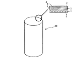
以下、図面を参照して、本発明の実施の形態を詳細に説明する。図1は被塗装物である円筒体からなる定着ベルトの端部を拡大して示す断面図である。図2は図1の基材の接着層を示す部分断面図である。
本発明を用いた塗膜形成装置及びこの塗膜形成装置を用いて加工したポリイミド基材を用いて製作した定着ベルトの実施の形態を図1及び図2を参照して説明する。図1の円内を示す断面図は定着ベルト30を無端状ベルト形状にする前の平らな状態として示している。
定着ベルト30(被塗装物)の基材1は、樹脂(ポリイミド、ポリアミドイミドなど)からなる材質で無端状ベルト形状をしている。その上に弾性層であるシリコンゴム2、離型層であるフッソ樹脂3(PFA、PTFEなど)がそれぞれプライマ層(接着層)4を介して構成されている。
また、この基材1のポリイミド樹脂はユーピレックス(商品名):宇部興産(50μm厚)を図に示すように接着層6を介して接合することで無端状ベルト形状を形成している。
基材1自体には導電性がないので、この基材1の円筒体内側(図1の断面図では下側)には本定着ベルトに導電性を持たせるための、カーボン分散液を塗布した導電層5が形成されている。本発明の塗膜形成装置はこの導電層5を塗装するためのものである。
本定着ベルトの加工順番は、まず、基材1を接合して円筒形状にした後に本発明の塗膜形成装置を用いて、導電層5を形成し、その後、基材1の円筒体外側(図1の断面図では内側)にプライマ層4、シリコンゴム層2、プライマ層4、離型層3の順に積層して塗装していく。この外側の層の塗装には、例えば、特許文献2に記載の塗膜形成装置や従来からのスプレーによる塗装などを用いて層を形成することが可能である。
Hereinafter, embodiments of the present invention will be described in detail with reference to the drawings. FIG. 1 is an enlarged cross-sectional view showing an end portion of a fixing belt made of a cylindrical body that is an object to be coated. FIG. 2 is a partial cross-sectional view showing an adhesive layer of the substrate of FIG.
An embodiment of a coating film forming apparatus using the present invention and a fixing belt manufactured using a polyimide base material processed using the coating film forming apparatus will be described with reference to FIGS. 1 is shown as a flat state before the
The
Moreover, the polyimide resin of this
Since the
The processing sequence of the fixing belt is as follows. First, the
図3は本発明による塗膜形成装置の実施の形態を示す概略図である。図3の塗膜形成装置において、ポリイミド樹脂の円筒体からなる被塗装物である定着ベルト基材1は円筒形状のマンドレル7に挿入され、基材1自体の元に戻ろうとする力でマンドレル7の内面に貼り付き円筒形状に保持されている。基材1及びマンドレル7は、塗装前には受け部材8上に載せられ(図示せず)、塗装中はチャック機構9によって図示されるように垂直に固定された状態で保持される。
被塗装物が無端状ベルト基材1の場合に、外周からこの無端状ベルト基材1を保持する保持具であるマンドレル7を具備しているので、不定形ベルト形状の被塗装物を真円に保持することが可能となり、少量の塗料で浸漬塗装にて表面性状がよく、被塗装物の内面に塗膜を形成することが可能である。
外周から基材1を保持するマンドレル7にエア(空気)で吸引するためのエア孔(空気)22が、少なくとも1個以上空いている。被塗装物である基材1をエア吸引することで、軸方向にずれないようにより強固に固定することが可能となる。
従って、被塗装物30の寸法が変化しても、少量の塗料で浸漬塗装にて、表面性状がよく被塗装物の内面に塗膜を形成することが可能である。図中、被塗装物30の内側には形成された塗膜20、エア孔22にはエア発生源(図示せず)に接続されるエア配管23が示してある。
FIG. 3 is a schematic view showing an embodiment of a coating film forming apparatus according to the present invention. In the coating film forming apparatus shown in FIG. 3, the fixing
When the object to be coated is the endless
At least one or more air holes (air) 22 for sucking with air (air) from the outer periphery to the
Therefore, even if the dimensions of the object to be coated 30 change, it is possible to form a coating film on the inner surface of the object to be coated by dip coating with a small amount of paint. In the drawing, the
液槽10内には塗料11が溜められる。塗料11は、図中の矢印Aから、図示されていないがポンプなどの定量供給装置を介して塗料タンクから塗料供給口21を通して供給され、塗装中に基材1の壁面を伝って漏れないように、弾性部材(ここではゴム部材t=0.5〜1.5mmのフッ素ゴムが最も良い)からなるたシール12で塗料11を封止している。
液槽10の上には蓋部材13があり、この蓋部材13の役割は塗料11が揮発したり、外部から塗料11内部に汚染物(コンタミネーション)が混入するのを防ぐことである。蓋部材13には垂下壁14が設けられており、これらの垂下壁14によりできる空間15は塗料11中に気泡が発生した場合に気泡が上昇し、この空間15に溜まることで、気泡をトラップすることが可能となる。
液面の高さは変位センサ18で測定しており(本実施の形態では超音波式のセンサを用いることで液面の高さも位置情報として検出することが可能である)、この変位センサ18の信号出力を図示してない本塗膜形成装置全体を制御する制御ユニットに送り、先述の定量供給装置を制御することで、塗料11により形成される液面の高さを任意の位置に制御することが可能となる。
液槽10はこの液槽10の上下に配置されるクランプ16で固定又は開放自在な構造となっており、クランプ16は上シャフト17A、下シャフト17Bに締結されており、直線運動案内機構19(本実施の形態ではリニアブッシュ)により案内され、上シャフト17A、下シャフト17Bのいずれのシャフトも上下に可動自在な構造となっている。
この上シャフト17A及び下シャフト17Bは図示されていない1軸直動アクチュエータで可動することができる。また、直線運動案内機構19は直線運動を案内する機械部品であり、シャフトの回りに配置したベアリングのごとき球体19aでシャフトの運動を案内している。
The
A
The height of the liquid level is measured by a displacement sensor 18 (in this embodiment, the height of the liquid level can be detected as position information by using an ultrasonic sensor). Is sent to a control unit for controlling the entire coating film forming apparatus (not shown), and the liquid level formed by the
The
The
図4は本発明の塗膜形成装置の塗装動作順序を説明する概略図である。図4ではこの塗装動作順序を図4(a)乃至(g)を用いて順に説明する。これらの図4(a)乃至(g)には図3と同一部分に同一符号を付すが、各図についての説明で必要以外の部分についてはそれらの説明を省略する。
初めに、図4(a)において、液槽10はシャフト17Aに取り付けられたクランプ16により上部に持ち上げられた状態になっており、この時、塗料11は溢れないようにシール12より下の位置に液面がくる状態になっている。
この状態で被塗装物30を形成する定着ベルト用基材1を受け部材8上に載せてセットする。この定着ベルト用基材1は不定形の無端状ベルト形状をしており、これ自体では形状を保持することができないために、マンドレル7に挿入され、基材1自体の戻ろうとする力でマンドレル7の内面に固定されている。
マンドレル7の内径は基材1の外径と同等から20〜30μmマイナスした公差で製作されているので、基材1が前述の復元力で張り付くと、この基材1の外面とマンドレル7内面の摩擦力によりこれらは簡単には動かないようになっている。
FIG. 4 is a schematic diagram for explaining the coating operation sequence of the coating film forming apparatus of the present invention. In FIG. 4, this painting operation sequence will be described in order with reference to FIGS. In FIGS. 4A to 4G, the same reference numerals are given to the same portions as those in FIG. 3, but the descriptions of the portions other than necessary in the descriptions of the drawings are omitted.
First, in FIG. 4A, the
In this state, the fixing
Since the inner diameter of the
次に、図4(b)において、本塗膜形成装置を起動すると、まずマンドレル7をチャック機構9が挟むことでマンドレル7は垂直に保持され固定される。この時、マンドレル7の軸心と液槽10の軸は同軸度0.2mm以下にすることが望ましい。
これは塗装に使用する塗料11の粘度にもよるが、あまりずれると4〜5cP程度の低粘度の塗料は漏れが生ずるためである。そしてマンドレル7が固定された後に受け部材8は下降し、液槽10の移動準備が完了する。受け部材8は図示していないが、エアシリンダなどの駆動源で上昇又は下降の動作をすることができる。
次いで、下シャフト17Bが図示していない1軸アクチュエータによって上昇し、下シャフト17Bの先端に設けられたクランプ16により、液槽10を下側から把持して固定する。液槽10が下側から保持されたら、上シャフト17Aに設けられたクランプ16は開放され、図4(c)の状態となる。
次に、図4(c)において、液槽10は図示位置まで移動し、ここで液槽10の液面高さは変位センサ18によりに計測され、その信号により制御ユニットが図示されていないポンプを運転し塗料11を補充し、所望の液面高さになった時点で塗料11の供給を停止する。
この時、塗料11中に気泡が存在する場合には、この気泡は塗料11中を上昇し、空間15に溜まることで気泡をトラップすることが可能となる。蓋部材13にある垂下壁14より外側に気泡がくることはないため、基材1に気泡が付着して、外観異常を発生することはない。
Next, in FIG. 4B, when the coating film forming apparatus is started, the
This depends on the viscosity of the
Next, the
Next, in FIG. 4C, the
At this time, if bubbles are present in the
次に、図(4d)に示すように、液槽10を下シャフト17Bのクランプ16で把持したまま、垂直方向下側に移動する。この時浸漬塗装の原理により、基材(被塗装物)1の内面には塗膜20が形成されることとなる。
塗膜20の厚さは、この時の液槽10の移動速度と塗料11の粘度により一義的に決定される。また、下シャフト17Bは直線運動案内機構19により、案内されているため、液槽10は前述の同軸度0.2mmを保ったまま下降することが可能である。
次に、図4(e)において、液槽10の図示位置で塗装は終了し、先程とは逆に液槽10内の塗料11を図示されていないポンプで回収し、液面をシール12より低い位置まで回収する。その後受け部材8が上昇し、チャック機構9を解除してマンドレル7を開放して取り出す。
定着ベルト基材1はこのマンドレル7にセットした状態で乾燥炉などを用いて乾燥した後に、マンドレル7から取り出す。その際、前述のように摩擦力で保持されているので、端部を一部剥がし、きっかけを作り、そこに図3に関連して上述したエアを流し込むことで、マンドレル7と基材1との間に空気層が設けられ、容易に外すことができる。塗膜形成装置は次の被塗装物を塗装するために、塗装開始のポジションまで戻る必要がある。
図4(f)に示すように、今度は上シャフト17Aが下降して、先端に固定されたクランプ16で液槽10を把持し、下シャフト17Bのクランプ16を解除した後に、上シャフト17Aが上方向に移動することで塗装開始前の位置である図4(g)に戻ることとなる。
次には、再び、図4(a)に戻り、次の被塗装物を塗装することができる。以上が本発明の塗膜形成措置を用いて被塗装物の内面を塗装する際の一連の動作である。
Next, as shown in FIG. 4D, the
The thickness of the
Next, in FIG. 4 (e), the coating is completed at the illustrated position of the
The fixing
As shown in FIG. 4 (f), this time the
Next, it returns to Fig.4 (a) again and the next to-be-coated object can be painted. The above is a series of operation | movement at the time of coating the inner surface of a to-be-coated object using the coating-film formation measure of this invention.
図5は本発明を実施した際の効果を表として示す図である。次に、本発明を実施した際の効果に関して図5に示す表を用いて説明する。基材1はポリイミドシート:ユーピレックス(商標)−S、厚み50μm(宇部興産)を図2のように接合して、φ50mmの長さ370mmのベルト状にしたものである。外面はまだ未塗装の状態である。塗料は、三井・デュポンフロロケミカル社、PL910BK(商品名)で、狙いの膜厚は10μmで塗装した状態で比較した。
比較例1は内面塗装用ノズルを用いて塗装した。比較例2は容器の中に被塗装物を浸した後に一定速度で引き上げる浸漬塗装にて塗装した場合、実施例は本発明の請求項1〜3を反映した塗膜形成装置にて塗装した場合の例である。
図5より、比較例1では表面性状が、本発明と比較して悪くなり、比較例2では表面性状は同等であるが、塗装に必要な塗料の量が多いことが解かり、これらを両立する上で本発明が有効であることが解かる。
本発明により製造された内面に塗膜を形成しているベルト状基体は、画像形成装置に用いられる定着ベルトとして、基材の表層に弾性層や離型層を形成する際に、内面の表面性状に影響されず、均一な塗膜を形成することができる。
FIG. 5 is a table showing the effects when the present invention is implemented. Next, the effect when the present invention is implemented will be described using the table shown in FIG. The
In Comparative Example 1, coating was performed using an inner surface coating nozzle. In Comparative Example 2, when the object to be coated is applied by dip coating that is pulled up at a constant speed after immersing the object to be coated in the container, the example is applied by a coating film forming
From FIG. 5, it can be seen that the surface property in Comparative Example 1 is worse than that of the present invention, and the surface property is the same in Comparative Example 2, but the amount of paint necessary for coating is large, and both are compatible. Thus, it is understood that the present invention is effective.
The belt-like substrate having a coating film formed on the inner surface according to the present invention is used as a fixing belt for use in an image forming apparatus, when an elastic layer or a release layer is formed on the surface layer of the substrate. A uniform coating film can be formed without being affected by properties.
図6は本発明による塗膜形成装置で塗装した定着ベルトを使用する画像形成装置の構成を簡略化して示す概略図である。図6の画像形成装置28において、帯電装置22によって帯電された感光体ドラム21には書き込み手段23によって静電潜像が書き込まれる。
この静電潜像は現像手段24の現像ローラ29上のトナーによって顕像化され、図示してない給紙手段からレジストローラ26に搬送された記録媒体Pがタイミングを合わせてレジストローラ26から感光体ドラム21と転写ローラ25とのニップに送られ、記録媒体P上に感光体ドラム21上のトナー像が転写される。
記録媒体P上に転写されたトナー像は、次に、熱と圧力でトナー像を記録媒体P上に定着させる定着手段27に送られる。この定着手段27は定着ベルト30と加圧ローラ31からなり、この定着ベルト30として本発明の塗膜形成装置を用いて製造された定着ベルト30を使用する。
FIG. 6 is a schematic view showing a simplified configuration of an image forming apparatus using a fixing belt coated with a coating film forming apparatus according to the present invention. In the
The electrostatic latent image is visualized by the toner on the developing
The toner image transferred onto the recording medium P is then sent to fixing means 27 that fixes the toner image on the recording medium P with heat and pressure. The fixing
1 円筒状基材(定着ベルト)、7 保持具(マンドレル)、9 チャック機構、10 液槽、11 塗料、12 シール部材、15 空間、16 クランプ機構、17A 上シャフト、17B 下シャフト、18 変位センサ、19 駆動機構(直線運動案内機構)、20 塗膜、 27 定着手段、28 画像形成装置、30 定着ベルト
DESCRIPTION OF
Claims (5)
Priority Applications (1)
| Application Number | Priority Date | Filing Date | Title |
|---|---|---|---|
| JP2008195080A JP5315834B2 (en) | 2008-07-29 | 2008-07-29 | Coating film forming apparatus, fixing means and image forming apparatus |
Applications Claiming Priority (1)
| Application Number | Priority Date | Filing Date | Title |
|---|---|---|---|
| JP2008195080A JP5315834B2 (en) | 2008-07-29 | 2008-07-29 | Coating film forming apparatus, fixing means and image forming apparatus |
Publications (2)
| Publication Number | Publication Date |
|---|---|
| JP2010029793A true JP2010029793A (en) | 2010-02-12 |
| JP5315834B2 JP5315834B2 (en) | 2013-10-16 |
Family
ID=41734935
Family Applications (1)
| Application Number | Title | Priority Date | Filing Date |
|---|---|---|---|
| JP2008195080A Expired - Fee Related JP5315834B2 (en) | 2008-07-29 | 2008-07-29 | Coating film forming apparatus, fixing means and image forming apparatus |
Country Status (1)
| Country | Link |
|---|---|
| JP (1) | JP5315834B2 (en) |
Cited By (3)
| Publication number | Priority date | Publication date | Assignee | Title |
|---|---|---|---|---|
| JP2011002658A (en) * | 2009-06-18 | 2011-01-06 | Ricoh Co Ltd | Substrate for fixing belt, method of manufacturing the same, fixing belt, method of manufacturing the fixing belt, and fixing device |
| CN102847648A (en) * | 2011-06-30 | 2013-01-02 | 中国二十冶集团有限公司 | Method for floating boat-type coating of interior of large-sized storage tank |
| CN104259044A (en) * | 2014-09-30 | 2015-01-07 | 芜湖盛力科技股份有限公司 | Oiling method of tank body oiling machine |
Citations (3)
| Publication number | Priority date | Publication date | Assignee | Title |
|---|---|---|---|---|
| US3885521A (en) * | 1972-05-24 | 1975-05-27 | Arx Paul Von | Apparatus for coating the inner wall surface of a duct |
| JPS61130382U (en) * | 1985-01-29 | 1986-08-15 | ||
| JP2007147909A (en) * | 2005-11-25 | 2007-06-14 | Fuji Xerox Co Ltd | Manufacturing method of cylindrical thin film elastic body |
-
2008
- 2008-07-29 JP JP2008195080A patent/JP5315834B2/en not_active Expired - Fee Related
Patent Citations (3)
| Publication number | Priority date | Publication date | Assignee | Title |
|---|---|---|---|---|
| US3885521A (en) * | 1972-05-24 | 1975-05-27 | Arx Paul Von | Apparatus for coating the inner wall surface of a duct |
| JPS61130382U (en) * | 1985-01-29 | 1986-08-15 | ||
| JP2007147909A (en) * | 2005-11-25 | 2007-06-14 | Fuji Xerox Co Ltd | Manufacturing method of cylindrical thin film elastic body |
Cited By (4)
| Publication number | Priority date | Publication date | Assignee | Title |
|---|---|---|---|---|
| JP2011002658A (en) * | 2009-06-18 | 2011-01-06 | Ricoh Co Ltd | Substrate for fixing belt, method of manufacturing the same, fixing belt, method of manufacturing the fixing belt, and fixing device |
| CN102847648A (en) * | 2011-06-30 | 2013-01-02 | 中国二十冶集团有限公司 | Method for floating boat-type coating of interior of large-sized storage tank |
| CN104259044A (en) * | 2014-09-30 | 2015-01-07 | 芜湖盛力科技股份有限公司 | Oiling method of tank body oiling machine |
| CN104259044B (en) * | 2014-09-30 | 2016-06-08 | 芜湖盛力科技股份有限公司 | A kind of oiling method of cylinder body oiler |
Also Published As
| Publication number | Publication date |
|---|---|
| JP5315834B2 (en) | 2013-10-16 |
Similar Documents
| Publication | Publication Date | Title |
|---|---|---|
| JP4787040B2 (en) | Coating film forming device | |
| JP2003045615A (en) | Metallic sleeve for heating and heating and fixing device | |
| JP5315834B2 (en) | Coating film forming apparatus, fixing means and image forming apparatus | |
| JP2014170225A (en) | Fixing device and image forming apparatus | |
| JP2011022274A (en) | Sheet material and image forming apparatus | |
| JP2008158447A (en) | Fixing member, fixing device, and image forming apparatus | |
| JP6172001B2 (en) | FIXING DEVICE MEMBER, FIXING DEVICE, AND IMAGE FORMING DEVICE | |
| JP2006255679A (en) | Manufacturing method and apparatus for cylinder with coated film | |
| JP2005238765A (en) | Method for covering base material with tube and fixing belt manufactured using it | |
| JP2008122907A (en) | Belt covered with fluororesin tube, manufacturing method thereof, fixing device and image forming apparatus | |
| JP2007252976A (en) | Coating head and coating film forming apparatus provided with the same | |
| JP4787041B2 (en) | Coating film forming device | |
| JP2005003781A (en) | Beltlike tubular member and image fixing device | |
| JP4857734B2 (en) | Method for producing cylindrical thin film elastic body | |
| JP2009268998A (en) | Coating device | |
| JP2002091027A (en) | Dip coating method, dip coating device and method for producing seamless belt | |
| JP2009018268A (en) | Method and apparatus for forming coated film | |
| JP6236917B2 (en) | Coating apparatus and coating method | |
| JP2008068236A (en) | Apparatus for forming coating film | |
| JP2016013532A (en) | Dip-coating equipment, and image carrier | |
| JP2008139777A (en) | Image heating film, and image heating apparatus using the same | |
| JP4614384B2 (en) | Coating method and belt member manufacturing method | |
| JP2001321708A (en) | Apparatus for immersion coating and method for producing photosensitive body for electrophotography | |
| JP2012088741A (en) | Heat fixing divice and metallic substrate used for sleeve thereof | |
| JP2005270807A (en) | Cyclic applicator and cyclic application method |
Legal Events
| Date | Code | Title | Description |
|---|---|---|---|
| A621 | Written request for application examination |
Free format text: JAPANESE INTERMEDIATE CODE: A621 Effective date: 20110422 |
|
| RD02 | Notification of acceptance of power of attorney |
Free format text: JAPANESE INTERMEDIATE CODE: A7422 Effective date: 20110426 |
|
| A131 | Notification of reasons for refusal |
Free format text: JAPANESE INTERMEDIATE CODE: A131 Effective date: 20121211 |
|
| A977 | Report on retrieval |
Free format text: JAPANESE INTERMEDIATE CODE: A971007 Effective date: 20121213 |
|
| A521 | Written amendment |
Free format text: JAPANESE INTERMEDIATE CODE: A523 Effective date: 20130208 |
|
| TRDD | Decision of grant or rejection written | ||
| A01 | Written decision to grant a patent or to grant a registration (utility model) |
Free format text: JAPANESE INTERMEDIATE CODE: A01 Effective date: 20130611 |
|
| A61 | First payment of annual fees (during grant procedure) |
Free format text: JAPANESE INTERMEDIATE CODE: A61 Effective date: 20130624 |
|
| LAPS | Cancellation because of no payment of annual fees |