JP2010027529A - 高周波加速器 - Google Patents
高周波加速器 Download PDFInfo
- Publication number
- JP2010027529A JP2010027529A JP2008190542A JP2008190542A JP2010027529A JP 2010027529 A JP2010027529 A JP 2010027529A JP 2008190542 A JP2008190542 A JP 2008190542A JP 2008190542 A JP2008190542 A JP 2008190542A JP 2010027529 A JP2010027529 A JP 2010027529A
- Authority
- JP
- Japan
- Prior art keywords
- frequency
- cavity
- acceleration
- resonators
- coaxial tube
- Prior art date
- Legal status (The legal status is an assumption and is not a legal conclusion. Google has not performed a legal analysis and makes no representation as to the accuracy of the status listed.)
- Granted
Links
Images


Landscapes
- Particle Accelerators (AREA)
Abstract
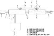
【解決手段】本発明の高周波加速器は、複数の高周波加速空洞共振器2,3を有し、各高周波加速空洞共振器2,3間が高周波同軸伝送路としての同軸管空洞7で結合され、この同軸管空洞7の両端部には同軸管空洞7を構成する外導体11と内導体12を接続するループ14が形成され、複数の高周波加速空洞共振器2,3と同軸管空洞7とは、その共振周波数が略同一で、かつ、同軸管空洞7の空洞長が共振波長の(1/2)・N倍(Nは自然数)でないように設定されている。
【選択図】図1
Description
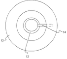
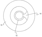
図1は本発明の実施の形態1における高周波加速器の構成図、図2は図1の符合Pで示す部分を拡大して示す断面図、図3は図2の部分を空洞共振器の空洞内部側から見た平面図である。
前段の空洞共振器2の出口から後段の空洞共振器3の入口までの距離Dは、各空洞共振器2,3の加速位相から決まる(この実施の形態1の場合には、荷電粒子が高周波電界の位相がπ+2nπ(nは整数)の間に進む長さとなる)ので、同軸管空洞7の横長部7aにおける水平方向の長さL1変更することはできない。そこで、この実施の形態1では、同軸管空洞7の各空洞共振器2,3内の表面と直交する軸方向の長さL2を調整するようにしている。
複数の空洞共振器が電磁気的に結合している場合には、各々の空洞共振器が結合した特性を示すようになる。この実施の形態1の場合には、前段の空洞共振器2、後段の空洞共振器3、および同軸管空洞7を互いに電磁気的に結合させる。その時、空洞共振器2,3の基本モードの加速周波数(共振周波数)と同軸管空洞7の最低次数の共振周波数は各々独立に存在する共振周波数からずれ、ある3種類の共振周波数となる。具体的には、0モード、π/2モード、πモードの3種類である。この内、π/2モードの共振周波数の場合、前段の空洞共振器2と後段の空洞共振器3との間の加速位相がちょうどπだけずれ、かつ、同軸管空洞7の加速電界がほぼ“0”になる。
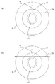
図10および図11は、前後2つの空洞共振器を用いて高周波加速電界を励起させる場合の構成例である。なお、図11(a)は図10の前段の空洞共振器を空洞内部側から見た平面図、図11(b)は図10の後段の空洞共振器を空洞内部側から見た平面図である。
その他の作用、効果は、実施の形態1の場合と同様であるから、ここでは詳しい説明は省略する。
上記の実施の形態1,2に記載した高周波加速器はHモード型加速器であり、このHモード型加速器においては、各空洞共振器2,3に生じる磁束は空洞軸方向に形成されるので、ループ14により囲まれた位置にある平面Srが空洞共振器2,3内の磁束方向Zと直交しているときを“0度”と定義している。
その他の作用、効果は、実施の形態1,2の場合と同様であるから、ここでは詳しい説明は省略する。
11 外導体、12 内導体、13 端板、14 ループ、15 回転角度計測手段。
Claims (4)
- 複数の高周波加速空洞共振器を有する高周波加速器において、
上記各高周波加速空洞共振器は、外導体と内導体で構成された高周波同軸伝送路で相互に結合され、上記高周波同軸伝送路は、その両端部に上記外導体と内導体とを接続するループが形成され、上記複数の高周波加速空洞共振器と上記高周波同軸伝送路とは、その共振周波数が略同一で、かつ、上記高周波同軸伝送路の空洞長は、共振波長の(1/2)・N倍(Nは自然数)とは異なる長さに設定されていることを特徴とする高周波加速器。 - 上記ループは、平面上に形成されたものであり、上記ループで囲まれた上記平面と上記高周波加速空洞共振器内の磁束方向とのなす角度、および高周波同軸伝送路の軸方向長さの少なくとも一方が可変に構成されたものであることを特徴とする請求項1記載の高周波加速器。
- 上記ループにより囲まれた上記平面と上記高周波加速空洞共振器内の磁束方向とのなす角度を計測する回転角度計測手段が設けられていることを特徴とする請求項1または請求項2に記載の高周波加速器。
- 上記高周波同軸伝送路の各端部には、リングの内径が内導体の外径より大きいリング状の端板が設けられていることを特徴とする請求項1ないし請求項3のいずれか1項に記載の高周波加速器。
Priority Applications (1)
| Application Number | Priority Date | Filing Date | Title |
|---|---|---|---|
| JP2008190542A JP4719255B2 (ja) | 2008-07-24 | 2008-07-24 | 高周波加速器 |
Applications Claiming Priority (1)
| Application Number | Priority Date | Filing Date | Title |
|---|---|---|---|
| JP2008190542A JP4719255B2 (ja) | 2008-07-24 | 2008-07-24 | 高周波加速器 |
Publications (2)
| Publication Number | Publication Date |
|---|---|
| JP2010027529A true JP2010027529A (ja) | 2010-02-04 |
| JP4719255B2 JP4719255B2 (ja) | 2011-07-06 |
Family
ID=41733148
Family Applications (1)
| Application Number | Title | Priority Date | Filing Date |
|---|---|---|---|
| JP2008190542A Active JP4719255B2 (ja) | 2008-07-24 | 2008-07-24 | 高周波加速器 |
Country Status (1)
| Country | Link |
|---|---|
| JP (1) | JP4719255B2 (ja) |
Cited By (2)
| Publication number | Priority date | Publication date | Assignee | Title |
|---|---|---|---|---|
| WO2014132391A1 (ja) | 2013-02-28 | 2014-09-04 | 三菱電機株式会社 | 高周波加速器の製造方法、高周波加速器、および円形加速器システム |
| US10098218B2 (en) | 2014-09-03 | 2018-10-09 | Mitsubishi Electric Corporation | Transportable linear accelerator system and transportable neutron source equipped therewith |
Citations (8)
| Publication number | Priority date | Publication date | Assignee | Title |
|---|---|---|---|---|
| JPS63224196A (ja) * | 1987-03-13 | 1988-09-19 | 石川島播磨重工業株式会社 | 高周波加速空胴 |
| JPH01213999A (ja) * | 1988-02-23 | 1989-08-28 | Toshiba Corp | 高周波加速空胴 |
| JPH0311600A (ja) * | 1989-06-08 | 1991-01-18 | Mitsubishi Electric Corp | 高周波加速空洞の周波数自動同調回路 |
| JPH03115369A (ja) * | 1989-09-28 | 1991-05-16 | Showa Electric Wire & Cable Co Ltd | 耐熱性塗料 |
| JPH0476300A (ja) * | 1990-07-16 | 1992-03-11 | Toshiba Corp | ポンプ系統 |
| JPH08172000A (ja) * | 1994-12-19 | 1996-07-02 | Toshiba Corp | 加速器の高周波加速装置 |
| JP2001060500A (ja) * | 1999-08-23 | 2001-03-06 | Mitsubishi Heavy Ind Ltd | 高周波空洞装置及び高周波加速器 |
| JP2001257099A (ja) * | 2000-01-06 | 2001-09-21 | Varian Medical Systems Inc | 切換可能なビームエネルギーを有する定常波粒子線加速器 |
-
2008
- 2008-07-24 JP JP2008190542A patent/JP4719255B2/ja active Active
Patent Citations (8)
| Publication number | Priority date | Publication date | Assignee | Title |
|---|---|---|---|---|
| JPS63224196A (ja) * | 1987-03-13 | 1988-09-19 | 石川島播磨重工業株式会社 | 高周波加速空胴 |
| JPH01213999A (ja) * | 1988-02-23 | 1989-08-28 | Toshiba Corp | 高周波加速空胴 |
| JPH0311600A (ja) * | 1989-06-08 | 1991-01-18 | Mitsubishi Electric Corp | 高周波加速空洞の周波数自動同調回路 |
| JPH03115369A (ja) * | 1989-09-28 | 1991-05-16 | Showa Electric Wire & Cable Co Ltd | 耐熱性塗料 |
| JPH0476300A (ja) * | 1990-07-16 | 1992-03-11 | Toshiba Corp | ポンプ系統 |
| JPH08172000A (ja) * | 1994-12-19 | 1996-07-02 | Toshiba Corp | 加速器の高周波加速装置 |
| JP2001060500A (ja) * | 1999-08-23 | 2001-03-06 | Mitsubishi Heavy Ind Ltd | 高周波空洞装置及び高周波加速器 |
| JP2001257099A (ja) * | 2000-01-06 | 2001-09-21 | Varian Medical Systems Inc | 切換可能なビームエネルギーを有する定常波粒子線加速器 |
Cited By (3)
| Publication number | Priority date | Publication date | Assignee | Title |
|---|---|---|---|---|
| WO2014132391A1 (ja) | 2013-02-28 | 2014-09-04 | 三菱電機株式会社 | 高周波加速器の製造方法、高周波加速器、および円形加速器システム |
| US9402298B2 (en) | 2013-02-28 | 2016-07-26 | Mitsubishi Electric Corporation | Method of manufacturing radio frequency accelerator, radio frequency accelerator, and circular accelerator system |
| US10098218B2 (en) | 2014-09-03 | 2018-10-09 | Mitsubishi Electric Corporation | Transportable linear accelerator system and transportable neutron source equipped therewith |
Also Published As
| Publication number | Publication date |
|---|---|
| JP4719255B2 (ja) | 2011-07-06 |
Similar Documents
| Publication | Publication Date | Title |
|---|---|---|
| US7898193B2 (en) | Slot resonance coupled standing wave linear particle accelerator | |
| Granatstein et al. | Gyro-amplifiers as candidate RF drivers for TeV linear colliders | |
| Wei et al. | Design and optimization of a longitudinal feedback kicker cavity for the HLS-Ⅱ storage ring | |
| Alesini | Power coupling | |
| US7276708B2 (en) | Diagnostic resonant cavity for a charged particle accelerator | |
| Ekdahl et al. | Long-pulse beam stability experiments on the DARHT-II linear induction accelerator | |
| JP4719255B2 (ja) | 高周波加速器 | |
| Gerigk | Cavity types | |
| Zhang et al. | Eigenvalue equations and numerical analysis of a coaxial cavity with misaligned inner rod | |
| EP2753155A2 (en) | Compact self-resonant x-ray source | |
| Schaer et al. | rf traveling-wave electron gun for photoinjectors | |
| Haebel | Couplers for cavities | |
| Shemelin et al. | Low-kick Twin-coaxial and Waveguide-coaxial Couplers for ERL | |
| Shaker et al. | Sub-harmonic buncher design for the CLIC drive beam injector | |
| Dehler et al. | X-band rf structure with integrated alignment monitors | |
| Dolgashev | Traveling wave linear accelerator with rf power flow outside of accelerating cavities | |
| Veshcherevich et al. | Buncher cavity for ERL | |
| Potter et al. | The Klynac: An integrated klystron and linear accelerator | |
| Ambattu et al. | Coupler induced monopole component and its minimization in deflecting cavities | |
| Rao et al. | Design, development, and acceleration trials of radio-frequency quadrupole | |
| Sekutowicz | TESLA superconducting accelerating structures | |
| Enomoto | Upgrade to the 8-GeV Electron Linac for KEKB | |
| Bogomyagkov et al. | Weak focusing low emittance storage ring with large 6d dynamic aperture based on canted cosine theta magnet technology | |
| Degiovanni | Accelerating Structures | |
| Liu et al. | Field stability of an Alvarez-type drift tube linear accelerator with small drift tubes |
Legal Events
| Date | Code | Title | Description |
|---|---|---|---|
| A621 | Written request for application examination |
Free format text: JAPANESE INTERMEDIATE CODE: A621 Effective date: 20101004 |
|
| A977 | Report on retrieval |
Free format text: JAPANESE INTERMEDIATE CODE: A971007 Effective date: 20110322 |
|
| TRDD | Decision of grant or rejection written | ||
| A01 | Written decision to grant a patent or to grant a registration (utility model) |
Free format text: JAPANESE INTERMEDIATE CODE: A01 Effective date: 20110329 |
|
| A01 | Written decision to grant a patent or to grant a registration (utility model) |
Free format text: JAPANESE INTERMEDIATE CODE: A01 |
|
| A61 | First payment of annual fees (during grant procedure) |
Free format text: JAPANESE INTERMEDIATE CODE: A61 Effective date: 20110401 |
|
| R150 | Certificate of patent or registration of utility model |
Ref document number: 4719255 Country of ref document: JP Free format text: JAPANESE INTERMEDIATE CODE: R150 Free format text: JAPANESE INTERMEDIATE CODE: R150 |
|
| FPAY | Renewal fee payment (event date is renewal date of database) |
Free format text: PAYMENT UNTIL: 20140408 Year of fee payment: 3 |
|
| R250 | Receipt of annual fees |
Free format text: JAPANESE INTERMEDIATE CODE: R250 |
|
| R250 | Receipt of annual fees |
Free format text: JAPANESE INTERMEDIATE CODE: R250 |
|
| R250 | Receipt of annual fees |
Free format text: JAPANESE INTERMEDIATE CODE: R250 |
|
| R250 | Receipt of annual fees |
Free format text: JAPANESE INTERMEDIATE CODE: R250 |
|
| R250 | Receipt of annual fees |
Free format text: JAPANESE INTERMEDIATE CODE: R250 |
|
| R250 | Receipt of annual fees |
Free format text: JAPANESE INTERMEDIATE CODE: R250 |
|
| R250 | Receipt of annual fees |
Free format text: JAPANESE INTERMEDIATE CODE: R250 |
|
| R250 | Receipt of annual fees |
Free format text: JAPANESE INTERMEDIATE CODE: R250 |
|
| R250 | Receipt of annual fees |
Free format text: JAPANESE INTERMEDIATE CODE: R250 |
|
| R250 | Receipt of annual fees |
Free format text: JAPANESE INTERMEDIATE CODE: R250 |