JP2010026541A - Developing cartridge and image forming device - Google Patents

Developing cartridge and image forming device Download PDF

Info

Publication number
JP2010026541A
JP2010026541A JP2009255251A JP2009255251A JP2010026541A JP 2010026541 A JP2010026541 A JP 2010026541A JP 2009255251 A JP2009255251 A JP 2009255251A JP 2009255251 A JP2009255251 A JP 2009255251A JP 2010026541 A JP2010026541 A JP 2010026541A
Authority
JP
Japan
Prior art keywords
developing cartridge
developing
roller
pressing
image
Prior art date
Legal status (The legal status is an assumption and is not a legal conclusion. Google has not performed a legal analysis and makes no representation as to the accuracy of the status listed.)
Granted
Application number
JP2009255251A
Other languages
Japanese (ja)
Other versions
JP4475361B2 (en
Inventor
Hiroshi Igarashi
宏 五十嵐
Naoya Kamimura
直哉 神村
Current Assignee (The listed assignees may be inaccurate. Google has not performed a legal analysis and makes no representation or warranty as to the accuracy of the list.)
Brother Industries Ltd
Original Assignee
Brother Industries Ltd
Priority date (The priority date is an assumption and is not a legal conclusion. Google has not performed a legal analysis and makes no representation as to the accuracy of the date listed.)
Filing date
Publication date
Application filed by Brother Industries Ltd filed Critical Brother Industries Ltd
Priority to JP2009255251A priority Critical patent/JP4475361B2/en
Publication of JP2010026541A publication Critical patent/JP2010026541A/en
Application granted granted Critical
Publication of JP4475361B2 publication Critical patent/JP4475361B2/en
Active legal-status Critical Current
Anticipated expiration legal-status Critical

Links

Images

Abstract

<P>PROBLEM TO BE SOLVED: To provide a developing cartridge that can continuously maintain a preferable pressing condition to press a developer carrier against an image carrier, and to provide an image forming apparatus equipped with the developing cartridge. <P>SOLUTION: The developing cartridge 27 may include a handle 214. A coil spring 218 is disposed, in a compressed state between the underside of the handle 214 and a contacting member 217. As a result, each time the developing cartridge 27 is replaced, a new coil spring 218 and handle 214 can be provided for a color laser printer, with the developing cartridge 27 attached. Accordingly, a constant pressure by the coil spring 218 can be maintained continuously, and the preferable pressure condition of the developer carrier 39 with respect to the photoreceptor drum 29 can be maintained continuously. <P>COPYRIGHT: (C)2010,JPO&INPIT

Description

本発明は、レーザプリンタなどの画像形成装置およびこれに備えられる現像カートリッジに関する。   The present invention relates to an image forming apparatus such as a laser printer and a developing cartridge provided in the image forming apparatus.

従来より、イエロー、マゼンタ、シアンおよびブラックの各色に対応した感光体が水平方向に並列に配置される、いわゆるタンデム型の画像形成装置が知られている。このタンデム型の画像形成装置では、各感光体に各色トナー像がほぼ同時に形成され、各感光体を順次通過する用紙に、各感光体から各色のトナー像を順次に色重ねして転写されるので、モノクロ画像形成装置とほぼ同じ速度でカラー画像を形成することができる。   2. Description of the Related Art Conventionally, a so-called tandem type image forming apparatus is known in which photosensitive members corresponding to yellow, magenta, cyan, and black are arranged in parallel in the horizontal direction. In this tandem type image forming apparatus, each color toner image is formed almost simultaneously on each photoconductor, and the toner images of each color are sequentially superimposed and transferred from the respective photoconductors to paper that sequentially passes through each photoconductor. Therefore, it is possible to form a color image at almost the same speed as the monochrome image forming apparatus.

このようなタンデム型の画像形成装置として、感光体に形成される静電潜像をトナー像に現像するための現像カートリッジを装置本体に対して着脱自在に備えたものが提案されている。たとえば、特許文献1では、各色の感光体をフレームで一体に支持した構成の感光体カートリッジを備え、この感光体カートリッジを装置本体に対してスライドにより装着および離脱可能に設けるとともに、各色の現像カートリッジを感光体カートリッジに対して着脱可能に設けたものが提案されている。   As such a tandem type image forming apparatus, there has been proposed an apparatus in which a developing cartridge for developing an electrostatic latent image formed on a photoreceptor into a toner image is detachable from the apparatus main body. For example, Patent Document 1 includes a photoconductor cartridge having a structure in which photoconductors of respective colors are integrally supported by a frame, and the photoconductor cartridge is provided to be slidable with respect to the apparatus main body by being slidable. Has been proposed that is detachable from the photosensitive cartridge.

現像カートリッジには、感光体にトナーを供給するための現像ローラが備えられている。装置本体には、ばねなどの弾性部材が備えられており、現像カートリッジが装置本体に装着された状態では、その弾性部材により現像カートリッジが付勢されて、現像ローラが感光体に対して所定の押圧力で押圧される。   The developing cartridge is provided with a developing roller for supplying toner to the photoreceptor. The apparatus main body is provided with an elastic member such as a spring. When the developing cartridge is mounted on the apparatus main body, the developing cartridge is urged by the elastic member, and the developing roller is fixed to the photosensitive member. Pressed with pressing force.

特開2003−15378号公報JP 2003-15378 A

しかし、弾性部材が現像カートリッジを付勢する付勢力は、弾性部材の劣化に伴って次第に減少する。弾性部材の付勢力が減少すると、感光体に対する現像ローラの押圧力が減少し、トナーの供給量不足に起因する現像不良を生じるおそれがある。
そこで、本発明の目的は、像担持体に対する現像剤担持体の良好な押圧状態を維持し続けることができる現像カートリッジおよびこれを備える画像形成装置を提供することにある。
However, the biasing force with which the elastic member biases the developing cartridge gradually decreases as the elastic member deteriorates. When the urging force of the elastic member is reduced, the pressing force of the developing roller against the photosensitive member is reduced, and there is a risk of developing failure due to insufficient supply of toner.
SUMMARY OF THE INVENTION Accordingly, an object of the present invention is to provide a developing cartridge that can keep a good pressing state of a developer carrying member against an image carrying member and an image forming apparatus including the developing cartridge.

前記の目的を達成するため、請求項1に記載の発明は、現像カートリッジにおいて、静電潜像が形成される像担持体に現像剤を供給して、当該静電潜像を可視像化するための現像剤担持体と、現像剤を収容し、前記現像剤担持体が支持される現像剤担持体支持部を一方側端部に有する筐体と、前記筐体における前記現像剤担持体支持部と反対側の他方側端部に、前記現像剤担持体の軸方向に延びる回動軸線を中心に回動自在に設けられ、前記筐体よりも前記現像剤担持体の軸方向における外方に突出し、外部から押圧力が入力される突出部、および、前記筐体の前記軸方向の側面よりも前記軸方向における内方に、前記軸方向に間隔を隔てて2つ設けられ、前記突出部に押圧力が入力されたときに、前記現像剤担持体が前記像担持体に押圧される方向に前記筐体を付勢する付勢部を有し、当該押圧力により回動して、前記付勢部を介して前記現像剤担持体が前記像担持体に押圧される方向に前記筐体を押圧する押圧部材とを備えていることを特徴としている。   In order to achieve the above object, according to the first aspect of the present invention, in the developing cartridge, a developer is supplied to an image carrier on which an electrostatic latent image is formed to visualize the electrostatic latent image. A developer carrying member for housing the developer, a housing that contains the developer and that supports the developer carrying member at one end, and the developer carrying member in the housing The other end of the developer carrier opposite to the support portion is provided so as to be rotatable about a rotation axis that extends in the axial direction of the developer carrier, and is located outside the housing in the axial direction of the developer carrier. Two protrusions projecting inwardly, and provided with a gap in the axial direction on the inner side in the axial direction than the side surface in the axial direction of the casing. When a pressing force is input to the protrusion, the developer carrier is pressed against the image carrier. A biasing portion that biases the housing in a direction in which the developer carrier is rotated by the pressing force, and the developer carrier is pressed against the image carrier via the biasing portion. And a pressing member that presses the housing.

このような構成によると、押圧部材が現像カートリッジに備えられているので、現像カートリッジの交換の度に、その現像カートリッジが装着される画像形成装置に新品の押圧部材を備えることができる。そのため、押圧部材が筐体を付勢する力を一定に保ち続けることができ、像担持体に対する現像剤担持体の良好な押圧状態を維持し続けることができる
請求項2に記載の発明は、請求項1に記載の発明において、前記押圧部材は、前記現像カートリッジを移動させる際に把持される取っ手を兼ねていることを特徴としている。
According to such a configuration, since the pressing member is provided in the developing cartridge, a new pressing member can be provided in the image forming apparatus to which the developing cartridge is mounted every time the developing cartridge is replaced. Therefore, the force by which the pressing member urges the housing can be kept constant, and the developer carrier can be kept in a good pressing state with respect to the image carrier. In the invention according to claim 1, the pressing member also serves as a handle to be gripped when the developing cartridge is moved.

このような構成によると、取っ手が備えられているので、その取っ手を把持して、現像器を移動させることができる。また、押圧部材が取っ手を兼ねるとともに、その押圧部材が回動自在であるので、取っ手として使用する際には開く方向に回動し、押圧部材として作用する際には閉じる方向に回動させることができる。しかも、押圧部材と取っ手とを別々に設けた構成よりも部品点数を少なくすることができる。そのため、現像カートリッジの操作性を優れたものとすることができながら、部品点数の低減を図ることができる。   According to such a configuration, since the handle is provided, the developing device can be moved by gripping the handle. In addition, since the pressing member also serves as a handle, the pressing member is rotatable, so that it is rotated in the opening direction when used as a handle, and is rotated in the closing direction when acting as a pressing member. Can do. Moreover, the number of parts can be reduced as compared with the configuration in which the pressing member and the handle are provided separately. Therefore, the number of parts can be reduced while the operability of the developing cartridge can be improved.

請求項3に記載の発明は、請求項1または2に記載の発明において、前記押圧部材に設けられ、前記押圧力による前記付勢部の弾性変形をガイドするガイド部材を備えていることを特徴としている。
このような構成によると、ガイド部材によって、付勢部の弾性変形がガイドされる。そのため、付勢部に押圧力が入力されるときに、付勢部の姿勢を安定に保ちながら、付勢部を弾性変形させることができる。その結果、現像剤担持体を像担持体に向けて確実に付勢することができる。
The invention according to claim 3 is the invention according to claim 1 or 2, further comprising a guide member provided on the pressing member for guiding elastic deformation of the urging portion due to the pressing force. It is said.
According to such a configuration, the elastic deformation of the urging portion is guided by the guide member. Therefore, when a pressing force is input to the urging unit, the urging unit can be elastically deformed while keeping the posture of the urging unit stable. As a result, the developer carrying member can be reliably urged toward the image carrying member.

請求項4に記載の発明は、請求項1ないし3のいずれかに記載の発明において、前記付勢部は、1N以上20N以下の付勢力を発生させることを特徴としている。
このような構成によると、付勢部の付勢力が1N以上であれば、付勢力の不足による現像剤担持体の像担持体に対する片当たりを防止することができる。また、付勢部の付勢力が20N以下であれば、付勢力が大きすぎることがなく、像担持体の所望しない領域に現像剤が付着する、いわゆる押圧かぶりの発生を防止することができる。
According to a fourth aspect of the present invention, in the invention according to any one of the first to third aspects, the urging portion generates an urging force of 1N or more and 20N or less.
According to such a configuration, if the urging force of the urging unit is 1 N or more, it is possible to prevent the developer carrying member from hitting the image carrying member due to insufficient urging force. Further, when the urging force of the urging unit is 20 N or less, the urging force is not excessively large, and it is possible to prevent the so-called press fogging in which the developer adheres to an undesired region of the image carrier.

請求項5に記載の発明は、請求項1ないし4のいずれかに記載の発明において、前記現像カートリッジは、各色に対応して設けられる複数の前記像担持体を備えるカラー画像形成装置に用いられることを特徴としている。
このような構成によると、現像カートリッジごとに、筐体に収容されている現像剤の種類(色)に応じた適切な付勢力を設定することができ、その付勢力により現像剤担持体を像担持体に対して良好に押圧させることができる。そのため、各像担持体にそれぞれ対応する色の現像剤を良好に供給することができる。
According to a fifth aspect of the present invention, in the invention according to any one of the first to fourth aspects, the developing cartridge is used in a color image forming apparatus including a plurality of the image carriers provided corresponding to the respective colors. It is characterized by that.
According to such a configuration, it is possible to set an appropriate urging force according to the type (color) of the developer contained in the housing for each developing cartridge, and the developer carrying member is imaged by the urging force. The carrier can be pressed well. Therefore, it is possible to satisfactorily supply a developer of a color corresponding to each image carrier.

請求項6に記載の発明は、請求項5に記載の発明において、前記現像カートリッジは、前記カラー画像形成装置において、前記筐体の前記一方側端部が相対的に下方に位置し、前記筐体の前記他方側端部が相対的に上方に位置するように配置されることを特徴としている。
このような構成では、現像カートリッジの自重が像担持体に対する現像剤担持体の押圧に作用する。そのため、筐体内に収容される現像剤量や筐体の設計が変更されることにより、現像カートリッジの自重が変わると、像担持体に対する現像剤担持体の押圧の状態が変化する。現像カートリッジに押圧部材が備えられているので、現像カートリッジの自重が変更されても、付勢部の付勢力を調節することにより、現像剤担持体を像担持体に対して所定の押圧状態で押圧させることができる。
According to a sixth aspect of the present invention, in the invention according to the fifth aspect, in the color image forming apparatus, the one end of the casing is positioned relatively downward in the developing cartridge. The other end of the body is disposed so as to be relatively positioned above.
In such a configuration, the weight of the developing cartridge acts on the pressing of the developer carrying member against the image carrying member. Therefore, when the developer amount stored in the housing and the design of the housing are changed, and the weight of the developing cartridge changes, the pressing state of the developer carrying body against the image carrier changes. Since the developing cartridge is provided with a pressing member, even if the weight of the developing cartridge is changed, the developer carrying member is kept in a predetermined pressing state against the image carrying member by adjusting the urging force of the urging unit. Can be pressed.

請求項7に記載の発明は、請求項5または6に記載の発明において、前記カラー画像形成装置は、装置本体と、前記装置本体に対して着脱可能に装着され、複数の前記像担持体を一体的に保持する像担持体ユニットとを備えており、前記現像カートリッジは、前記像担持体ユニットに対して着脱可能に装着され、前記押圧部材は、前記現像カートリッジが前記像担持体ユニットに装着された状態で、前記像担持体ユニットの着脱方向と交差する方向に延びる回動軸線を中心に、当該着脱方向と交差する起立状態と前記像担持体ユニットの装着時の移動方向の上流側に傾倒する傾倒状態とに回動可能に設けられていることを特徴としている。   According to a seventh aspect of the present invention, in the invention according to the fifth or sixth aspect, the color image forming apparatus is detachably attached to the apparatus main body and the apparatus main body, and a plurality of the image carriers are arranged. An image carrier unit that is integrally held, the developer cartridge is detachably attached to the image carrier unit, and the pressing member is attached to the image carrier unit by the developing member. In a state where the image carrier unit is mounted, an upright state extending in a direction intersecting with the attaching / detaching direction of the image carrier unit and an upstream side in the moving direction when the image carrier unit is mounted, with the standing state intersecting with the attaching / detaching direction. It is characterized by being provided so as to be able to rotate in a tilted state in which it tilts.

このような構成によると、押圧部材が起立状態と傾倒状態とに回動可能に設けられているので、像担持体ユニットを装置本体に装着するときに、起立状態の押圧部材の移動経路上に障害物(装置本体の構成部材)が存在しても、その起立状態の押圧部材は、障害物との衝突により起立状態から傾倒状態に回動する。そのため、押圧部材が像担持体ユニットの装着の妨げになるのを防止することができ、像担持体ユニットの装置本体に対するスムーズな装着を確保することができる。   According to such a configuration, since the pressing member is rotatably provided in the standing state and the tilted state, when the image carrier unit is mounted on the apparatus main body, the pressing member is placed on the moving path of the pressing member in the standing state. Even if there is an obstacle (a component of the apparatus main body), the pressing member in the standing state rotates from the standing state to the tilted state due to a collision with the obstacle. Therefore, it is possible to prevent the pressing member from interfering with the mounting of the image carrier unit, and it is possible to ensure the smooth mounting of the image carrier unit to the apparatus main body.

請求項8に記載の発明は、画像形成装置において、請求項1ないし7のいずれかに記載の現像カートリッジと、前記押圧部材に押圧力を入力する押圧力入力部材とを備えていることを特徴としている。
このような構成によると、像担持体に対する現像剤担持体の良好な押圧状態を維持し続けることができる現像カートリッジを備えているので、現像剤担持体から像担持体への現像剤の良好な供給を確保することができる。そのため、像担持体に形成される静電潜像の良好な可視像化を達成することができ、高品質な画像を形成することができる。
According to an eighth aspect of the present invention, in the image forming apparatus, the developing cartridge according to any one of the first to seventh aspects and a pressing force input member that inputs a pressing force to the pressing member are provided. It is said.
According to such a configuration, since the developer cartridge capable of maintaining a good pressing state of the developer carrier against the image carrier is provided, the developer from the developer carrier to the image carrier is excellent. Supply can be secured. Therefore, it is possible to achieve a good visible image of the electrostatic latent image formed on the image carrier, and it is possible to form a high quality image.

請求項9に記載の発明は、請求項8に記載の発明において、装置本体と、前記装置本体に対して着脱可能に装着され、複数の像担持体を一体的に保持する像担持体ユニットとを備え、前記現像カートリッジは、前記像担持体ユニットに対して着脱可能に装着されることを特徴としている。
このような構成によると、複数の像担持体を保持する像担持体ユニットを、装置本体に対して着脱させることができる。そのため、ジャム処理や部品交換などのメンテナンス作業の容易化を図ることができる。
According to a ninth aspect of the present invention, in the eighth aspect of the invention, an apparatus main body, and an image carrier unit that is detachably attached to the apparatus main body and integrally holds a plurality of image carriers. The developing cartridge is detachably attached to the image carrier unit.
According to such a configuration, the image carrier unit holding a plurality of image carriers can be attached to and detached from the apparatus main body. Therefore, it is possible to facilitate maintenance work such as jam processing and parts replacement.

また、複数の現像カートリッジを像担持体ユニットに対して着脱可能に装着することができる。そのため、現像カートリッジを個別に交換することができ、メンテナンスのための費用(メンテナンスコスト)の低減を図ることができる。   In addition, a plurality of developing cartridges can be detachably attached to the image carrier unit. Therefore, the developing cartridge can be individually replaced, and the maintenance cost (maintenance cost) can be reduced.

請求項1に記載の発明によれば、像担持体に対する現像剤担持体の良好な押圧状態を維持し続けることができる。
請求項2に記載の発明によれば、現像カートリッジの操作性を優れたものとすることができながら、部品点数の低減を図ることができる。
請求項3に記載の発明によれば、現像剤担持体を像担持体に向けて確実に付勢することができる。
According to the first aspect of the present invention, it is possible to continue to maintain a good pressing state of the developer carrier against the image carrier.
According to the second aspect of the present invention, it is possible to reduce the number of parts while improving the operability of the developing cartridge.
According to the third aspect of the present invention, the developer carrying member can be reliably urged toward the image carrying member.

請求項4に記載の発明によれば、現像剤担持体の像担持体に対する片当たりおよび押圧かぶりの発生を防止することができる。
請求項5に記載の発明によれば、各像担持体にそれぞれ対応する色の現像剤を良好に供給することができる。
請求項6に記載の発明によれば、現像カートリッジの自重が変更されても、付勢部の付勢力を調節することにより、現像剤担持体を像担持体に対して所定の押圧状態で押圧させることができる。
According to the fourth aspect of the present invention, it is possible to prevent the developer carrying member from contacting the image carrying member with respect to the image carrying member and the occurrence of press fogging.
According to the fifth aspect of the present invention, it is possible to satisfactorily supply the color developer corresponding to each image carrier.
According to the sixth aspect of the present invention, even if the dead weight of the developing cartridge is changed, the developer carrier is pressed against the image carrier in a predetermined pressing state by adjusting the biasing force of the biasing portion. Can be made.

請求項7に記載の発明によれば、押圧部材が像担持体ユニットの装着の妨げになるのを防止することができ、像担持体ユニットの装置本体に対するスムーズな装着を確保することができる。
請求項8に記載の発明によれば、像担持体に形成される静電潜像の良好な可視像化を達成することができ、高品質な画像を形成することができる。
According to the seventh aspect of the present invention, it is possible to prevent the pressing member from interfering with the mounting of the image carrier unit, and to ensure the smooth mounting of the image carrier unit to the apparatus main body.
According to the eighth aspect of the invention, it is possible to achieve good visualization of the electrostatic latent image formed on the image carrier, and it is possible to form a high-quality image.

請求項9に記載の発明によれば、ジャム処理や部品交換などのメンテナンス作業の容易化を図ることができ、かつ、メンテナンスコストの低減を図ることができる。   According to the ninth aspect of the present invention, it is possible to facilitate maintenance work such as jam processing and parts replacement, and it is possible to reduce maintenance costs.

本発明のカラー画像形成装置の一例としてのカラーレーザプリンタの一実施形態を示す側断面図である。1 is a side sectional view showing an embodiment of a color laser printer as an example of a color image forming apparatus of the present invention. 図1に示す現像カートリッジおよびドラムサブユニットの側断面図である。FIG. 2 is a side sectional view of the developing cartridge and the drum subunit shown in FIG. 1. 図1に示すドラムユニット(4つの現像カートリッジが装着された状態)の左後上方から見た斜視図である。FIG. 2 is a perspective view of the drum unit (in a state where four developing cartridges are mounted) shown in FIG. 図1に示すドラムユニット(1つの現像カートリッジが着脱途中であり、その他の現像カートリッジが離脱された状態)の左前上方から見た斜視図である。FIG. 2 is a perspective view of the drum unit shown in FIG. 1 (one developing cartridge is being attached / detached and other developing cartridges are detached) as viewed from the upper left front. 図1に示すドラムユニットの左側面図である。It is a left view of the drum unit shown in FIG. 図1に示す現像カートリッジの左後方から見た斜視図であり、取っ手の傾倒状態が示されている。FIG. 2 is a perspective view of the developing cartridge shown in FIG. 1 as viewed from the left rear, showing a tilted state of the handle. 図1に示す現像カートリッジの左後方から見た斜視図であり、取っ手の起立状態が示されている。FIG. 2 is a perspective view of the developing cartridge shown in FIG. 1 as seen from the left rear, showing a standing state of the handle. 図1に示す現像カートリッジの左前方から見た斜視図であり、取っ手の傾倒状態が示されている。FIG. 2 is a perspective view of the developing cartridge shown in FIG. 1 as viewed from the left front, showing a tilted state of the handle. 図1に示す現像カートリッジの左前方から見た斜視図であり、取っ手の起立状態が示されている。FIG. 2 is a perspective view of the developing cartridge shown in FIG. 1 as viewed from the left front, showing a standing state of the handle. 図1に示す現像カートリッジの平面図である。FIG. 2 is a plan view of the developing cartridge shown in FIG. 図1に示す現像カートリッジの右側面図である。FIG. 2 is a right side view of the developing cartridge shown in FIG. 1. 図11に示す現像カートリッジの切断線A−Aにおける断面図である。FIG. 12 is a sectional view of the developing cartridge shown in FIG. 11 taken along a cutting line AA. 図1に示す現像カートリッジの右側断面図であり、取っ手の傾倒状態が示されている。FIG. 2 is a right side sectional view of the developing cartridge shown in FIG. 1, showing a tilted state of the handle. 図1に示す現像カートリッジの右側断面図であり、取っ手の押圧状態が示されている。FIG. 2 is a right side sectional view of the developing cartridge shown in FIG. 1, showing a pressing state of a handle. 図1に示す本体ケーシングおよびドラムユニットの右前上方から見た斜視図であり、本体ケーシングの外装板およびフロントカバーが取り外され、その本体ケーシングにドラムユニットが装着された状態が示されている。FIG. 2 is a perspective view of the main body casing and the drum unit shown in FIG. 1 as viewed from the upper right front, and shows a state in which an exterior plate and a front cover of the main body casing are removed and the drum unit is mounted on the main body casing. 図15に示すドラムユニットならびに左右のレールおよび離間押圧機構の右前上方から見た斜視図である。It is the perspective view seen from the front right upper part of the drum unit shown in FIG. 図16に示すレールおよび離間押圧機構の右前上方から見た斜視図である。FIG. 17 is a perspective view of the rail and the separation pressing mechanism shown in FIG. 図17に示す直動カム部材、中間部材および同期移動機構の右前上方から見た斜視図である。FIG. 18 is a perspective view of the linear cam member, the intermediate member, and the synchronous movement mechanism shown in FIG. 図18に示す直動カム部材および中間部材の動きを説明するための斜視図である。It is a perspective view for demonstrating the motion of the linear cam member and intermediate member shown in FIG. 図19(a)の状態における直動カム部材および中間部材の右側面図である。It is a right view of the linear cam member and intermediate member in the state of Fig.19 (a). 図19(c)の状態における直動カム部材および中間部材の右側面図である。It is a right view of the linear cam member and intermediate member in the state of FIG.19 (c). 図19(e)の状態における直動カム部材および中間部材の右側面図である。It is a right view of the linear cam member and intermediate member in the state of FIG.19 (e). 現像カートリッジの他の実施形態(板ばね部材を備える態様)を示す斜視図である。It is a perspective view which shows other embodiment (aspect provided with a leaf | plate spring member) of a developing cartridge. 現像カートリッジの他の実施形態(現像フレームの上壁の幅方向全幅にわたって弾性部材を設ける態様)を示す斜視図であり、取っ手の傾倒状態が示されている。FIG. 10 is a perspective view showing another embodiment of the developing cartridge (an aspect in which an elastic member is provided over the entire width in the width direction of the upper wall of the developing frame), and shows a tilted state of the handle. 図24に示す現像カートリッジの斜視図であり、取っ手の起立状態が示されている。FIG. 25 is a perspective view of the developing cartridge shown in FIG. 24, showing the handle standing up. 現像カートリッジの他の実施形態(押圧突起に弾性リングが装着される態様)を示す斜視図であり、その現像カートリッジの右前上方から見た状態が示されている。FIG. 10 is a perspective view showing another embodiment of the developing cartridge (an aspect in which an elastic ring is attached to the pressing protrusion), and shows a state of the developing cartridge as viewed from the upper right front. 図26に示す現像カートリッジの左前上方から見た状態が示されている。The state seen from the upper left front of the developing cartridge shown in FIG. 26 is shown. 図27に示す現像カートリッジの左側上端部の斜視図である。FIG. 28 is a perspective view of a left upper end portion of the developing cartridge shown in FIG. 27. 現像カートリッジの他の実施形態(コイルばねが取っ手に設けられる態様)を示す左前方から見た斜視図であり、取っ手の傾倒状態が示されている。It is the perspective view seen from the left front which shows other embodiment (a mode in which a coil spring is provided in a handle), and a tilted state of a handle is shown. 図29に示す現像カートリッジの左前方から見た斜視図であり、取っ手の起立状態が示されている。It is the perspective view seen from the left front of the developing cartridge shown in FIG. 29, and the standing state of the handle is shown. 図29に示す現像カートリッジの前方から見た正面図である。FIG. 30 is a front view of the developing cartridge shown in FIG. 29 as viewed from the front. 図31に示す現像カートリッジの切断線B−Bにおける断面図である。FIG. 32 is a cross-sectional view of the developing cartridge shown in FIG. 31 taken along section line BB.

1.カラーレーザプリンタの全体構成
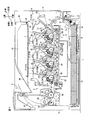
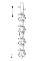
図1は、本発明のカラー画像形成装置の一例としてのカラーレーザプリンタの一実施形態を示す側断面図である。
このカラーレーザプリンタ1は、後述する複数のドラムサブユニット28が水平方向において並列的に配置される、横置きタイプのタンデム型カラーレーザプリンタであって、装置本体の一例としての本体ケーシング2内に、用紙3を給紙するための給紙部4と、給紙された用紙3に画像を形成するための画像形成部5と、画像が形成された用紙3を排紙するための排紙部6とを備えている。
(1)本体ケーシング
本体ケーシング2は、側面視略矩形状のボックス形状をなしており、その内部に、後述するドラムユニット26を収容するドラム収容空間7が形成されている。
1. 1 is a side sectional view showing an embodiment of a color laser printer as an example of a color image forming apparatus of the present invention.
This color laser printer 1 is a horizontal tandem color laser printer in which a plurality of drum subunits 28 to be described later are arranged in parallel in a horizontal direction, and is disposed in a main body casing 2 as an example of an apparatus main body. A paper feed unit 4 for feeding the paper 3, an image forming unit 5 for forming an image on the fed paper 3, and a paper discharge unit for discharging the paper 3 on which the image is formed 6 is provided.
(1) Main Body Casing The main body casing 2 has a box shape that is substantially rectangular when viewed from the side, and a drum housing space 7 that houses a drum unit 26 described later is formed therein.

本体ケーシング2の一方側面には、ドラム収容空間7に連通する着脱口8が形成されている。また、その着脱口8が形成されている側面には、着脱口8を開閉するためのフロントカバー9が設けられている。このフロントカバー9は、本体ケーシング2の側方に傾倒して、着脱口8を開放し、本体ケーシング2の一方側面に沿って起立して、着脱口8を閉鎖する。着脱口8を開放した状態で、この着脱口8を介して、ドラムユニット26をドラム収容空間7に対して着脱させることができる。   An attachment / detachment port 8 communicating with the drum housing space 7 is formed on one side surface of the main casing 2. A front cover 9 for opening and closing the attachment / detachment port 8 is provided on a side surface where the attachment / detachment port 8 is formed. The front cover 9 tilts to the side of the main body casing 2 to open the attachment / detachment opening 8, rises along one side surface of the main body casing 2, and closes the attachment / detachment opening 8. The drum unit 26 can be attached to and detached from the drum housing space 7 through the attachment / detachment opening 8 with the attachment / detachment opening 8 opened.

なお、以下の説明において、フロントカバー9が設けられる側(図1における右側)を前側とし、その反対側(図1における左側)を後側とする。また、このカラーレーザプリンタ1を前側から見たときを左右の基準とする。さらに、ドラムユニット26および現像カートリッジ27に関しては、特に言及がない限り、本体ケーシング2に装着されている状態で前後左右上下を規定する。
(2)給紙部
給紙部4は、本体ケーシング2内の底部に設けられている。この給紙部4は、用紙3を収容する給紙トレイ10と、その給紙トレイ10の前端部上方に設けられ、互いに対向配置される分離ローラ11および分離パッド12と、分離ローラ11の後側に設けられる給紙ローラ13と、用紙3が通過する給紙側搬送経路14とを備えている。
In the following description, the side on which the front cover 9 is provided (the right side in FIG. 1) is the front side, and the opposite side (the left side in FIG. 1) is the rear side. Further, when the color laser printer 1 is viewed from the front side, the left and right reference is used. Further, with respect to the drum unit 26 and the developing cartridge 27, the front / rear, left / right, upper / lower are defined in the state where the drum unit 26 and the developing cartridge 27 are attached to the main casing 2 unless otherwise specified.
(2) Paper Feed Unit The paper feed unit 4 is provided at the bottom of the main body casing 2. The paper feed unit 4 includes a paper feed tray 10 that stores the paper 3, a separation roller 11 and a separation pad 12 that are provided above the front end of the paper feed tray 10, and are disposed opposite to each other. The sheet feeding roller 13 provided on the side and the sheet feeding side conveyance path 14 through which the sheet 3 passes are provided.

給紙側搬送経路14は、側面視略U字状に形成されており、その上流側端部が分離ローラ11に隣接し、その下流側端部が後述する搬送ベルト58に前側から隣接している。
給紙側搬送経路14の途中には、分離ローラ11の前側上方に設けられ、互いに対向配置される紙粉取りローラ15およびピンチローラ16と、それらの上方に設けられる1対のレジストローラ17とが設けられている。
The sheet feeding side conveyance path 14 is formed in a substantially U shape in a side view, and its upstream end is adjacent to the separation roller 11 and its downstream end is adjacent to a conveyance belt 58 described later from the front side. Yes.
A paper dust removing roller 15 and a pinch roller 16 which are provided on the upper front side of the separation roller 11 and are arranged opposite to each other in the middle of the paper feeding side conveyance path 14, and a pair of registration rollers 17 provided above them. Is provided.

給紙トレイ10の内部には、用紙3が積層状に載置される用紙押圧板18が設けられている。この用紙押圧板18は、後端部において揺動自在に支持されることによって、前端部が下方に配置され、給紙トレイ10の底板に沿う載置位置と、前端部が上方に配置され、傾斜する給紙位置との間で移動自在とされている。
また、給紙トレイ10の前端部下方には、用紙押圧板18の前端部を上方に持ち上げるレバー19が設けられている。このレバー19は、用紙押圧板18の前端部下方において、上下方向に揺動自在に支持されている。
Inside the paper feed tray 10, a paper pressing plate 18 on which the paper 3 is placed in a stacked manner is provided. The sheet pressing plate 18 is supported swingably at the rear end portion, so that the front end portion is disposed below, the placement position along the bottom plate of the sheet feeding tray 10 and the front end portion are disposed above, It is possible to move between an inclined paper feeding position.
A lever 19 that lifts the front end of the paper pressing plate 18 upward is provided below the front end of the paper feed tray 10. The lever 19 is supported in a vertically swingable manner below the front end of the paper pressing plate 18.

そして、レバー19の揺動により、用紙押圧板18の前端部が、レバー19によって持ち上げられ、用紙押圧板18が給紙位置に位置される。
用紙押圧板18が給紙位置に位置されると、用紙押圧板18上の最上位の用紙3は、給紙ローラ13に押圧され、給紙ローラ13の回転によって、分離ローラ11と分離パッド12との間に向けて給紙される。
As the lever 19 swings, the front end of the paper pressing plate 18 is lifted by the lever 19 and the paper pressing plate 18 is positioned at the paper feeding position.
When the sheet pressing plate 18 is positioned at the sheet feeding position, the uppermost sheet 3 on the sheet pressing plate 18 is pressed by the sheet feeding roller 13, and the separation roller 11 and the separation pad 12 are rotated by the rotation of the sheet feeding roller 13. Paper is fed in between.

なお、給紙トレイ10を本体ケーシング2から離脱させると、用紙押圧板18が載置位置に位置される。用紙押圧板18が載置位置に位置されると、用紙押圧板18上に用紙3を積層状に載置することができる。
給紙された用紙3は、分離ローラ11の回転によって、分離ローラ11と分離パッド12との間に挟まれ、1枚ごとに捌かれて搬送される。搬送された用紙3は、紙粉取りローラ15とピンチローラ16との間を通過し、紙粉が除去された後、給紙側搬送経路14に沿ってレジストローラ17に向けて搬送される。
When the paper feed tray 10 is detached from the main casing 2, the paper pressing plate 18 is positioned at the placement position. When the paper pressing plate 18 is positioned at the mounting position, the paper 3 can be stacked on the paper pressing plate 18.
The fed paper 3 is sandwiched between the separation roller 11 and the separation pad 12 by the rotation of the separation roller 11, and is fed and conveyed one by one. The transported paper 3 passes between the paper dust removing roller 15 and the pinch roller 16, and after the paper dust is removed, it is transported toward the registration roller 17 along the paper feed side transport path 14.

レジストローラ17は、用紙3を、レジスト後に、搬送ベルト58に搬送する。
(3)画像形成部
画像形成部5は、スキャナ部20、プロセス部21、転写部22および定着部23を備えている。
(3−1)スキャナ部
スキャナ部20は、本体ケーシング2の上部に配置されている。このスキャナ部20は、前後左右方向に延びる支持板24と、この支持板24の上面に固定されるスキャナユニット25とを備えている。スキャナユニット25内には、たとえば、4つの光源、ポリゴンミラー、fθレンズ、反射鏡、面倒れ補正レンズなどの光学部材が配置されており、各光源から発光される画像データに基づくレーザビームは、ポリゴンミラーで偏向および走査されて、fθレンズおよび面倒れ補正レンズを通過し、また、反射鏡で反射された後、後述する各色の感光ドラム29の表面上に高速走査にて照射される。
(3−2)プロセス部
プロセス部21は、スキャナ部20の下方であって、給紙部4の上方に配置されており、1つの像担持体ユニットの一例としてのドラムユニット26と、各色に対応する4つの現像カートリッジ27とを備えている。
(3−2−1)ドラムユニット
ドラムユニット26は、各色に対応して、4つのドラムサブユニット28を備えている。すなわち、ドラムサブユニット28は、ブラックドラムサブユニット28K。イエロードラムサブユニット28Y、マゼンタドラムサブユニット28Mおよびシアンドラムサブユニット28Cの4つからなる。
The registration roller 17 conveys the paper 3 to the conveyance belt 58 after registration.
(3) Image Forming Unit The image forming unit 5 includes a scanner unit 20, a process unit 21, a transfer unit 22, and a fixing unit 23.
(3-1) Scanner Unit The scanner unit 20 is disposed on the upper part of the main body casing 2. The scanner unit 20 includes a support plate 24 extending in the front-rear and left-right directions, and a scanner unit 25 fixed to the upper surface of the support plate 24. In the scanner unit 25, for example, optical members such as four light sources, a polygon mirror, an fθ lens, a reflecting mirror, and a surface tilt correction lens are arranged, and a laser beam based on image data emitted from each light source is The light is deflected and scanned by the polygon mirror, passes through the fθ lens and the surface tilt correction lens, is reflected by the reflecting mirror, and then is irradiated onto the surface of the photosensitive drum 29 for each color described later at high speed scanning.
(3-2) Process Unit The process unit 21 is disposed below the scanner unit 20 and above the paper feed unit 4, and corresponds to each drum unit 26 as an example of one image carrier unit. The four developing cartridges 27 are provided.
(3-2-1) Drum Unit The drum unit 26 includes four drum subunits 28 corresponding to each color. That is, the drum subunit 28 is the black drum subunit 28K. It consists of four units, a yellow drum subunit 28Y, a magenta drum subunit 28M, and a cyan drum subunit 28C.

各ドラムサブユニット28は、互いに前後方向に間隔を隔てて並列的に配置されており、より具体的には、前側から後側に向かって、ブラックドラムサブユニット28K。イエロードラムサブユニット28Y、マゼンタドラムサブユニット28Mおよびシアンドラムサブユニット28Cが、順次配置されている。
各ドラムサブユニット28は、後述するように、1対のサイドフレーム104と、これらの間に架設されるセンタフレーム105とを備えている(図4参照)。
The respective drum subunits 28 are arranged in parallel at intervals in the front-rear direction, and more specifically, the black drum subunit 28K from the front side toward the rear side. A yellow drum subunit 28Y, a magenta drum subunit 28M, and a cyan drum subunit 28C are sequentially arranged.
As will be described later, each drum subunit 28 includes a pair of side frames 104 and a center frame 105 installed between them (see FIG. 4).

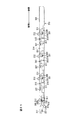
図2は、現像カートリッジ27およびドラムサブユニット28の側断面図である。なお、図1および図2においては、後述する取っ手214の図示が省略されている。
各ドラムサブユニット28は、図2に示すように、像担持体の一例としての感光ドラム29と、スコロトロン型帯電器30と、クリーニングブラシ31とを保持している。
感光ドラム29は、左右方向に沿って配置され、円筒形状をなし、最表層がポリカーボネートからなる正帯電性の感光層により形成されるドラム本体32と、このドラム本体32の軸線方向に沿って配置されるドラム軸33とを備えている。ドラム本体32は、ドラム軸33に対して回転自在に設けられている。ドラム軸33は、軸方向両端部が、1対のサイドフレーム104(図4参照)に挿通され、後述する側板103(図4参照)に回転不能に支持されている。そして、感光ドラム29は、画像形成時において、本体ケーシング2内に設けられるモータ(図示せず)からの駆動力により回転される。
FIG. 2 is a side sectional view of the developing cartridge 27 and the drum subunit 28. In FIGS. 1 and 2, the handle 214 described later is not shown.
As shown in FIG. 2, each drum subunit 28 holds a photosensitive drum 29 as an example of an image carrier, a scorotron charger 30, and a cleaning brush 31.
The photosensitive drum 29 is arranged along the left-right direction, has a cylindrical shape, and is arranged along the axial direction of the drum body 32 formed by a positively chargeable photosensitive layer whose outermost layer is made of polycarbonate. The drum shaft 33 is provided. The drum body 32 is provided so as to be rotatable with respect to the drum shaft 33. Both end portions in the axial direction of the drum shaft 33 are inserted into a pair of side frames 104 (see FIG. 4), and are rotatably supported by a side plate 103 (see FIG. 4) described later. The photosensitive drum 29 is rotated by a driving force from a motor (not shown) provided in the main body casing 2 during image formation.

スコロトロン型帯電器30は、感光ドラム29の斜め上側後方に、感光ドラム29と間隔を隔てて対向配置され、センタフレーム105に保持されている。このスコロトロン型帯電器30は、感光ドラム29と間隔を隔てて対向配置された放電ワイヤ34と、放電ワイヤ34と感光ドラム29との間に設けられるグリッド35とを備えている。画像形成時には、放電ワイヤ34に高電圧が印加されて、放電ワイヤ34がコロナ放電するとともに、グリッド35に電圧が印加されて、感光ドラム29に供給される電荷量が制御されつつ、感光ドラム29の表面が一様に正極性に帯電される。   The scorotron charger 30 is disposed diagonally above and behind the photosensitive drum 29 so as to face the photosensitive drum 29 with a space therebetween and is held by the center frame 105. The scorotron charger 30 includes a discharge wire 34 disposed to face the photosensitive drum 29 with a space therebetween, and a grid 35 provided between the discharge wire 34 and the photosensitive drum 29. At the time of image formation, a high voltage is applied to the discharge wire 34 to cause corona discharge of the discharge wire 34, and a voltage is applied to the grid 35 to control the amount of charge supplied to the photosensitive drum 29 while controlling the photosensitive drum 29. Are uniformly charged to the positive polarity.

クリーニングブラシ31は、感光ドラム29の後方において、感光ドラム29と対向して接触するように配置され、センタフレーム105に保持されている。画像形成時には、クリーニングブラシ31にクリーニングバイアスが印加される。
(3−2−2)現像カートリッジ
現像カートリッジ27は、図1に示すように、各色に対応するドラムサブユニット28に対応して、それぞれ着脱自在に設けられている。すなわち、現像カートリッジ27は、ブラックドラムサブユニット28Kに着脱自在に装着されるブラック現像カートリッジ27K、イエロードラムサブユニット28Yに着脱自在に装着されるイエロー現像カートリッジ27Y、マゼンタドラムサブユニット28Mに着脱自在に装着されるマゼンタ現像カートリッジ27M、および、シアンドラムサブユニット28Cに着脱自在に装着されるシアン現像カートリッジ27Cの4つからなる。
The cleaning brush 31 is disposed behind the photosensitive drum 29 so as to face and contact the photosensitive drum 29, and is held by the center frame 105. During image formation, a cleaning bias is applied to the cleaning brush 31.
(3-2-2) Developing Cartridge As shown in FIG. 1, the developing cartridge 27 is detachably provided corresponding to the drum subunit 28 corresponding to each color. That is, the developing cartridge 27 is detachably attached to the black developing cartridge 27K detachably attached to the black drum subunit 28K, the yellow developing cartridge 27Y detachably attached to the yellow drum subunit 28Y, and the magenta drum subunit 28M. The magenta developing cartridge 27M is mounted, and the cyan developing cartridge 27C is detachably mounted on the cyan drum subunit 28C.

各現像カートリッジ27は、図2に示すように、筐体の一例としての現像フレーム36と、その現像フレーム36内に設けられる、アジテータ37、供給ローラ38、現像剤担持体の一例としての現像ローラ39および層厚規制ブレード40とを備えている。
現像フレーム36は、下端部に開口部41が開口されるボックス形状に形成されており、隔壁42によって、トナー収容室43と現像室44とに区画されている。また、隔壁42には、トナー収容室43と現像室44とを連通する連通口45が形成されている。
As shown in FIG. 2, each developing cartridge 27 includes a developing frame 36 as an example of a housing, and an agitator 37, a supply roller 38, and a developing roller as an example of a developer carrier provided in the developing frame 36. 39 and a layer thickness regulating blade 40.
The developing frame 36 is formed in a box shape having an opening 41 at the lower end, and is divided into a toner storage chamber 43 and a developing chamber 44 by a partition wall 42. The partition wall 42 is formed with a communication port 45 that allows the toner storage chamber 43 and the development chamber 44 to communicate with each other.

トナー収容室43には、各色に対応するトナーが収容されている。より具体的には、各現像カートリッジ27に対応して、ブラック現像カートリッジ27Kにはブラック、イエロー現像カートリッジ27Yにはイエロー、マゼンタ現像カートリッジ27Mにはマゼンタ、シアン現像カートリッジ27Cにはシアンのトナーが、それぞれ収容されている。
各色に対応するトナーは、正帯電性の非磁性1成分の重合トナーが用いられる。重合トナーは、略球形であり、スチレンなどのスチレン系単量体や、アクリル酸、アルキル(C1〜C4)アクリレート、アルキル(C1〜C4)メタアクリレートなどのアクリル系単量体を、懸濁重合などの公知の重合方法によって共重合させることにより得られる、結着樹脂を主成分とし、これに、各色に対応する着色剤や、荷電制御剤、ワックスなどが配合されることによりトナー母粒子が形成され、さらに、流動性の向上を図るべく外添剤が添加されてなる。
The toner storage chamber 43 stores toner corresponding to each color. More specifically, corresponding to each developing cartridge 27, black toner is applied to the black developing cartridge 27K, yellow toner to the yellow developing cartridge 27Y, magenta toner to the magenta developing cartridge 27M, and cyan toner to the cyan developing cartridge 27C. Each is housed.
As the toner corresponding to each color, a positively charged non-magnetic one-component polymerized toner is used. The polymerized toner has a substantially spherical shape and is a suspension polymerization of a styrene monomer such as styrene or an acrylic monomer such as acrylic acid, alkyl (C1 to C4) acrylate, or alkyl (C1 to C4) methacrylate. Obtained by copolymerization by a known polymerization method such as a binder resin as a main component, and by adding a colorant corresponding to each color, a charge control agent, a wax and the like, toner base particles are obtained. In addition, an external additive is added to improve the fluidity.

着色剤としては、上記した、ブラック、イエロー、マゼンタおよびシアンの各着色剤が、各色に対応して配合されている。また、荷電制御剤としては、たとえば、アンモニウム塩などのイオン性官能基を有するイオン性単量体と、スチレン系単量体やアクリル系単量体などのイオン性単量体と共重合可能な単量体との共重合によって得られる荷電制御樹脂が配合されている。また、外添剤としては、たとえば、シリカ、酸化アルミニウム、酸化チタン、チタン酸ストロンチウム、酸化セリウム、酸化マグネシウムなどの金属酸化物の粉末や、炭化物の粉末、金属塩の粉末などの無機粉末が配合されている。   As the colorant, the above-described black, yellow, magenta and cyan colorants are blended corresponding to each color. Moreover, as a charge control agent, for example, an ionic monomer having an ionic functional group such as an ammonium salt and an ionic monomer such as a styrene monomer or an acrylic monomer can be copolymerized. A charge control resin obtained by copolymerization with a monomer is blended. As external additives, for example, powders of metal oxides such as silica, aluminum oxide, titanium oxide, strontium titanate, cerium oxide and magnesium oxide, inorganic powders such as carbide powders and metal salt powders are blended. Has been.

アジテータ37は、トナー収容室43内に設けられている。アジテータ37は、現像フレーム36の後述する両側壁201に回転自在に支持されるアジテータ回転軸47と、そのアジテータ回転軸47の軸方向にわたって設けられ、回転軸から径方向外方に延びる攪拌部材48とを備えている。画像形成時において、アジテータ回転軸47には、本体ケーシング2内に設けられるモータ(図示せず)からの駆動力が伝達され、攪拌部材48がトナー収容室43内を周回移動する。   The agitator 37 is provided in the toner storage chamber 43. The agitator 37 is provided over the axial direction of the agitator rotating shaft 47 that is rotatably supported on both side walls 201 described later of the developing frame 36, and the stirring member 48 that extends radially outward from the rotating shaft. And. At the time of image formation, a driving force from a motor (not shown) provided in the main body casing 2 is transmitted to the agitator rotating shaft 47, and the agitating member 48 moves around in the toner storage chamber 43.

供給ローラ38は、現像室44内において、連通口45の下方に設けられている。この供給ローラ38は、現像フレーム36の両側壁201に回転自在に支持される金属製の供給ローラ軸49と、その供給ローラ軸49の周りを被覆する導電性のスポンジからなるスポンジローラ50とを備えている。画像形成時には、本体ケーシング2内に設けられるモータ(図示せず)からの駆動力が伝達され、供給ローラ38が回転される。   The supply roller 38 is provided below the communication port 45 in the developing chamber 44. The supply roller 38 includes a metal supply roller shaft 49 that is rotatably supported on both side walls 201 of the developing frame 36, and a sponge roller 50 made of a conductive sponge that covers the periphery of the supply roller shaft 49. I have. At the time of image formation, a driving force from a motor (not shown) provided in the main body casing 2 is transmitted, and the supply roller 38 is rotated.

現像ローラ39は、現像室44内において、供給ローラ38に対して斜め後側下方に設けられている。この現像ローラ39は、現像フレーム36に回転自在に支持される金属製の現像ローラ軸51と、その現像ローラ軸51の周りを被覆する導電性のゴムからなるゴムローラ52とを備えている。
ゴムローラ52は、カーボン微粒子などを含む導電性のウレタンゴム、シリコーンゴムまたはEPDMゴムなどからなるゴムローラ層と、そのゴムローラ層の表面に被覆され、ウレタンゴム、ウレタン樹脂、ポリイミド樹脂などを主成分とするコート層との2層構造からなる。
The developing roller 39 is provided in the developing chamber 44 obliquely rearward and downward with respect to the supply roller 38. The developing roller 39 includes a metal developing roller shaft 51 that is rotatably supported by the developing frame 36 and a rubber roller 52 made of conductive rubber that covers the periphery of the developing roller shaft 51.
The rubber roller 52 is coated with a rubber roller layer made of conductive urethane rubber, silicone rubber, EPDM rubber or the like containing carbon fine particles, and the surface of the rubber roller layer, and mainly contains urethane rubber, urethane resin, polyimide resin, or the like. It consists of a two-layer structure with a coat layer.

現像ローラ39は、供給ローラ38に対して、ゴムローラ52とスポンジローラ50とが互いに圧接するように配置されている。また、現像ローラ39は、現像室44の開口部41から下方に向けて露出するように配置されている。
画像形成時には、本体ケーシング2内に設けられるモータ(図示せず)からの駆動力が伝達され、現像ローラ39が回転される。また、現像ローラ39には、現像バイアスが印加される。
The developing roller 39 is disposed so that the rubber roller 52 and the sponge roller 50 are in pressure contact with the supply roller 38. The developing roller 39 is disposed so as to be exposed downward from the opening 41 of the developing chamber 44.
During image formation, a driving force from a motor (not shown) provided in the main body casing 2 is transmitted, and the developing roller 39 is rotated. A developing bias is applied to the developing roller 39.

層厚規制ブレード40は、現像室44内において、現像ローラ39に上方から圧接するように設けられている。層厚規制ブレード40は、金属製の板ばね部材からなるブレード53と、ブレード53の遊端部に設けられる絶縁性のシリコーンゴムからなる断面半円形状の押圧部54とを備えている。
ブレード53の基端部が、固定部材55によって隔壁42に固定されており、ブレード53の弾性力により、ブレード53の遊端部に設けられる押圧部54が、現像ローラ39のゴムローラ52に対して上方から圧接される。
(3−2−3)プロセス部での現像動作
そして、各現像カートリッジ27では、トナー収容室43に収容されている各色に対応するトナーが、自重によって連通口45に移動し、アジテータ37によって攪拌されながら、連通口45から現像室44へ放出される。
The layer thickness regulating blade 40 is provided in the developing chamber 44 so as to be in pressure contact with the developing roller 39 from above. The layer thickness regulating blade 40 includes a blade 53 made of a metal leaf spring member, and a pressing portion 54 having a semicircular cross section made of insulating silicone rubber provided at the free end of the blade 53.
The base end portion of the blade 53 is fixed to the partition wall 42 by a fixing member 55, and the pressing portion 54 provided at the free end portion of the blade 53 against the rubber roller 52 of the developing roller 39 by the elastic force of the blade 53. Press contact from above.
(3-2-3) Developing Operation in Process Unit In each developing cartridge 27, the toner corresponding to each color stored in the toner storage chamber 43 moves to the communication port 45 by its own weight and is stirred by the agitator 37. While being done, it is discharged from the communication port 45 to the developing chamber 44.

連通口45から現像室44へ放出されたトナーは、供給ローラ38に供給される。供給ローラ38に供給されたトナーは、供給ローラ38の回転により、現像ローラ39に供給され、このとき、供給ローラ38と、現像バイアスが印加されている現像ローラ39との間で正極性に摩擦帯電される。
現像ローラ39に供給されたトナーは、現像ローラ39の回転に伴って、層厚規制ブレード40の押圧部54と、現像ローラ39のゴムローラ52との間に進入して、一定厚さの薄層としてゴムローラ52の表面に担持される。
The toner discharged from the communication port 45 to the developing chamber 44 is supplied to the supply roller 38. The toner supplied to the supply roller 38 is supplied to the developing roller 39 by the rotation of the supply roller 38. At this time, the toner is positively rubbed between the supply roller 38 and the developing roller 39 to which the developing bias is applied. Charged.
The toner supplied to the developing roller 39 enters between the pressing portion 54 of the layer thickness regulating blade 40 and the rubber roller 52 of the developing roller 39 as the developing roller 39 rotates, and a thin layer having a constant thickness. Is carried on the surface of the rubber roller 52.

一方、各現像カートリッジ27に対応するドラムサブユニット28では、スコロトロン型帯電器30が、コロナ放電を発生させて、感光ドラム29の表面を一様に正帯電させる。
感光ドラム29の表面は、感光ドラム29の回転に伴って、スコロトロン型帯電器30により一様に正帯電された後、スキャナ部20からのレーザビームの高速走査により露光され、用紙3に形成すべき画像に対応した静電潜像が形成される。
On the other hand, in the drum subunit 28 corresponding to each developing cartridge 27, the scorotron charger 30 generates corona discharge to uniformly positively charge the surface of the photosensitive drum 29.
The surface of the photosensitive drum 29 is uniformly positively charged by the scorotron charger 30 as the photosensitive drum 29 rotates, and then exposed by high-speed scanning of the laser beam from the scanner unit 20 to form on the paper 3. An electrostatic latent image corresponding to the power image is formed.

感光ドラム29がさらに回転すると、現像ローラ39の表面に担持されかつ正帯電されているトナーが、現像ローラ39の回転により、感光ドラム29に対向して接触するときに、感光ドラム29の表面に形成されている静電潜像、すなわち、一様に正帯電されている感光ドラム29の表面のうち、レーザビームによって露光され電位が下がっている露光部分に供給される。これにより、感光ドラム29の静電潜像は、現像により可視像化され、感光ドラム29の表面には、各色に対応して、反転現像によるトナー像が担持される。   When the photosensitive drum 29 further rotates, the positively charged toner carried on the surface of the developing roller 39 comes into contact with the surface of the photosensitive drum 29 when the developing roller 39 rotates and contacts the photosensitive drum 29. The formed electrostatic latent image, that is, the surface of the uniformly positively charged photosensitive drum 29 is supplied to an exposed portion exposed to a laser beam and having a lowered potential. As a result, the electrostatic latent image on the photosensitive drum 29 is visualized by development, and a toner image by reversal development is carried on the surface of the photosensitive drum 29 corresponding to each color.

なお、転写後に感光ドラム29上に残存する転写残トナーは、現像ローラ39に回収される。また、転写後に感光ドラム29上に付着する用紙3からの紙粉は、クリーニングブラシ31によって回収される。
(3−3)転写部
転写部22は、図1に示すように、本体ケーシング2内において、給紙部4の上方であって、プロセス部21の下方において、前後方向に沿って配置されている。この転写部22は、駆動ローラ56、従動ローラ57、搬送ベルト58、転写ローラ59およびクリーニング部60を備えている。
The transfer residual toner remaining on the photosensitive drum 29 after the transfer is collected by the developing roller 39. Further, the paper dust from the paper 3 adhering to the photosensitive drum 29 after the transfer is collected by the cleaning brush 31.
(3-3) Transfer Unit As shown in FIG. 1, the transfer unit 22 is disposed along the front-rear direction in the main body casing 2 above the paper feed unit 4 and below the process unit 21. Yes. The transfer unit 22 includes a driving roller 56, a driven roller 57, a conveyance belt 58, a transfer roller 59, and a cleaning unit 60.

駆動ローラ56および従動ローラ57は、前後方向に間隔を隔てて対向配置されており、駆動ローラ56は、シアンドラムサブユニット28Cよりも後方に配置され、従動ローラ57は、ブラックドラムサブユニット28Kよりも前方に配置されている。
搬送ベルト58は、エンドレスベルトからなり、カーボンなどの導電性粒子を分散した導電性のポリカーボネートやポリイミドなどの樹脂フィルムから形成されている。この搬送ベルト58は、駆動ローラ56と従動ローラ57との間に巻回されている。
The driving roller 56 and the driven roller 57 are arranged to face each other with a space in the front-rear direction, the driving roller 56 is arranged behind the cyan drum subunit 28C, and the driven roller 57 is from the black drum subunit 28K. Is also placed forward.
The conveyance belt 58 is an endless belt, and is formed from a conductive resin film such as conductive polycarbonate or polyimide in which conductive particles such as carbon are dispersed. The conveyor belt 58 is wound between the driving roller 56 and the driven roller 57.

画像形成時において、駆動ローラ56には、本体ケーシング2内に設けられる図示しないモータからの駆動力が伝達され、駆動ローラ56が回転される。すると、搬送ベルト58が、駆動ローラ56および従動ローラ57の間を、各ドラムサブユニット28の感光ドラム29と対向して接触する転写位置において、感光ドラム29と逆方向に回転するように周回移動されるとともに、従動ローラ57が従動される。   During image formation, a driving force from a motor (not shown) provided in the main body casing 2 is transmitted to the driving roller 56, and the driving roller 56 is rotated. Then, the conveyor belt 58 rotates between the driving roller 56 and the driven roller 57 so as to rotate in the opposite direction to the photosensitive drum 29 at the transfer position where the conveying belt 58 faces and contacts the photosensitive drum 29 of each drum subunit 28. At the same time, the driven roller 57 is driven.

転写ローラ59は、駆動ローラ56および従動ローラ57の間に巻回されている搬送ベルト58内において、各感光ドラム29と、搬送ベルト58を挟んで対向するように、それぞれ設けられている。各転写ローラ59は、金属製のローラ軸に、導電性のゴムからなるゴムローラが被覆されている。また、各転写ローラ59は、搬送ベルト58と対向して接触する転写位置において、搬送ベルト58の周回移動方向と同方向に従動回転するように設けられており、画像形成時には、本体ケーシング2内に設けられる図示しない高圧基板からの転写バイアスが印加される。   The transfer roller 59 is provided in the conveyance belt 58 wound between the driving roller 56 and the driven roller 57 so as to face each photosensitive drum 29 with the conveyance belt 58 interposed therebetween. Each transfer roller 59 has a metal roller shaft covered with a rubber roller made of conductive rubber. Each transfer roller 59 is provided so as to be driven and rotated in the same direction as the circumferential movement direction of the conveyor belt 58 at a transfer position facing and contacting the conveyor belt 58. A transfer bias is applied from a high-voltage substrate (not shown) provided in FIG.

クリーニング部60は、駆動ローラ56および従動ローラ57の間に巻回されている搬送ベルト58の下方に配置され、1次クリーニングローラ61、2次クリーニングローラ62、掻取ブレード63およびトナー貯留部64を備えている。
1次クリーニングローラ61は、感光ドラム29および転写ローラ59が接触する上側の搬送ベルト58と反対側の、下側の搬送ベルト58と接触するように配置され、その接触位置において、搬送ベルト58の周回移動方向と同方向に駆動回転するように設けられている。1次クリーニングローラ61には、画像形成時に、1次クリーニングバイアスが印加される。
The cleaning unit 60 is disposed below the conveying belt 58 wound between the driving roller 56 and the driven roller 57, and the primary cleaning roller 61, the secondary cleaning roller 62, the scraping blade 63, and the toner storage unit 64. It has.
The primary cleaning roller 61 is disposed so as to contact the lower conveyance belt 58 on the side opposite to the upper conveyance belt 58 with which the photosensitive drum 29 and the transfer roller 59 are in contact. It is provided so as to be driven and rotated in the same direction as the circumferential movement direction. A primary cleaning bias is applied to the primary cleaning roller 61 during image formation.

2次クリーニングローラ62は、1次クリーニングローラ61に対して下方から接触するように配置され、その接触位置において、1次クリーニングローラ61の回転方向と逆方向に回転するように設けられている。2次クリーニングローラ62には、画像形成時に、2次クリーニングバイアスが印加される。
掻取ブレード63は、2次クリーニングローラ62に対して下方から接触するように設けられている。
The secondary cleaning roller 62 is disposed so as to come into contact with the primary cleaning roller 61 from below, and is provided to rotate in the direction opposite to the rotation direction of the primary cleaning roller 61 at the contact position. A secondary cleaning bias is applied to the secondary cleaning roller 62 during image formation.
The scraping blade 63 is provided so as to contact the secondary cleaning roller 62 from below.

トナー貯留部64は、1次クリーニングローラ61および2次クリーニングローラ62の下方において、2次クリーニングローラ62から落下するトナーを貯留できるように設けられている。
そして、給紙部4から給紙された用紙3は、駆動ローラ56の駆動および従動ローラ57の従動により周回移動される搬送ベルト58によって、前側から後側に向かって、各ドラムサブユニット28に対応する転写位置を、順次通過するように搬送され、その搬送中に、各ドラムサブユニット28の感光ドラム29に担持されている各色のトナー像が、順次転写され、これにより、用紙3にカラー像が形成される。
The toner storage unit 64 is provided below the primary cleaning roller 61 and the secondary cleaning roller 62 so as to store toner falling from the secondary cleaning roller 62.
Then, the sheet 3 fed from the sheet feeding unit 4 is transferred to each drum subunit 28 from the front side to the rear side by the conveyance belt 58 that is circulated by the driving roller 56 and the driven roller 57. The toner images of the respective colors carried on the photosensitive drums 29 of the respective drum subunits 28 are sequentially transferred during the conveyance so as to pass through the corresponding transfer positions. An image is formed.

すなわち、たとえば、ブラックドラムサブユニット28Kの感光ドラム29の表面に担持されたブラックのトナー像が、用紙3に転写されると、次いで、イエロードラムサブユニット28Yの感光ドラム29の表面に担持されたイエローのトナー像が、既にブラックのトナー像が転写されている用紙3に重ねて転写され、以下同様の動作によって、マゼンタドラムサブユニット28Mの感光ドラム29の表面に担持されたマゼンタのトナー像、シアンドラムサブユニット28Cの感光ドラム29の表面に担持されたシアンのトナー像が重ねて転写され、これによって、用紙3にカラー像が形成される。   That is, for example, when a black toner image carried on the surface of the photosensitive drum 29 of the black drum subunit 28K is transferred to the paper 3, it is then carried on the surface of the photosensitive drum 29 of the yellow drum subunit 28Y. The yellow toner image is transferred onto the paper 3 on which the black toner image has already been transferred, and the magenta toner image carried on the surface of the photosensitive drum 29 of the magenta drum subunit 28M by the same operation. A cyan toner image carried on the surface of the photosensitive drum 29 of the cyan drum subunit 28 </ b> C is transferred in a superimposed manner, whereby a color image is formed on the paper 3.

一方、上記の転写動作において、搬送ベルト58の表面に付着したトナーは、クリーニング部60において、まず、搬送ベルト58の表面から、1次クリーニングバイアスにより1次クリーニングローラ61に転写され、さらに、2次クリーニングバイアスにより2次クリーニングローラ62に転写される。その後、2次クリーニングローラ62に転写されたトナーは、掻取ブレード63によって、掻き取られ、2次クリーニングローラ62から落下して、トナー貯留部64に貯留される。
(3−4)定着部
定着部23は、本体ケーシング2におけるシアンドラムサブユニット28Cよりも後側であって、感光ドラム29と搬送ベルト58とが接触する転写位置と、前後方向において対向するように配置されている。この定着部23は、加熱ローラ65および加圧ローラ66を備えている。
On the other hand, in the above transfer operation, the toner adhering to the surface of the conveyor belt 58 is first transferred from the surface of the conveyor belt 58 to the primary cleaning roller 61 by the primary cleaning bias in the cleaning unit 60, and further to 2 The toner is transferred to the secondary cleaning roller 62 by the next cleaning bias. Thereafter, the toner transferred to the secondary cleaning roller 62 is scraped off by the scraping blade 63, falls from the secondary cleaning roller 62, and is stored in the toner storage portion 64.
(3-4) Fixing Unit The fixing unit 23 is located behind the cyan drum subunit 28C in the main body casing 2 and faces the transfer position where the photosensitive drum 29 and the conveyance belt 58 are in contact with each other in the front-rear direction. Is arranged. The fixing unit 23 includes a heating roller 65 and a pressure roller 66.

加熱ローラ65は、その表面に離型層が形成される金属素管からなり、その軸方向に沿ってハロゲンランプが内装されている。加熱ローラ65は、ハロゲンランプにより、その表面が定着温度に加熱される。
加圧ローラ66は、加熱ローラ65の下方において、加熱ローラ65と対向配置されている。この加圧ローラ66は、加熱ローラ65を下方から押圧する。
The heating roller 65 is made of a metal base tube having a release layer formed on the surface thereof, and a halogen lamp is provided along the axial direction thereof. The surface of the heating roller 65 is heated to a fixing temperature by a halogen lamp.
The pressure roller 66 is disposed below the heating roller 65 so as to face the heating roller 65. The pressure roller 66 presses the heating roller 65 from below.

用紙3上に転写されたカラー像は、この定着部23に搬送され、用紙3が加熱ローラ65と加圧ローラ66との間を通過する間に、その用紙3に熱定着される。これにより、用紙3への画像の形成が達成される。
(4)排紙部
排紙部6において、用紙3の排紙側搬送経路67は、その上流側端部が、下方において定着部23に隣接し、その下流側端部が、上方において排紙トレイ68に隣接しており、用紙3が後側に向かって給紙され、反転後、前側に向かって排紙される、側面視略U字状に形成されている。
The color image transferred onto the sheet 3 is conveyed to the fixing unit 23 and is thermally fixed to the sheet 3 while the sheet 3 passes between the heating roller 65 and the pressure roller 66. Thereby, formation of an image on the sheet 3 is achieved.
(4) Paper Discharge Unit In the paper discharge unit 6, the paper discharge side transport path 67 of the paper 3 has an upstream end adjacent to the fixing unit 23 at the lower side and a downstream end at the upper side. Adjacent to the tray 68, the sheet 3 is formed in a substantially U shape in a side view so that the sheet 3 is fed toward the rear side, and after being reversed, the sheet 3 is ejected toward the front side.

排紙側搬送経路67の途中には、互いに対向する搬送ローラ69およびピンチローラ70が設けられている。また、排紙側搬送経路67の下流側端部には、1対の排紙ローラ71が設けられている。
また、排紙部6には、排紙トレイ68が設けられている。排紙トレイ68は、本体ケーシング2の上壁を、前側から後側に向かって次第に窪むように形成して、排紙される用紙3を積層状に載置できるように、形成されている。
A transport roller 69 and a pinch roller 70 that face each other are provided in the middle of the paper discharge side transport path 67. A pair of paper discharge rollers 71 is provided at the downstream end of the paper discharge side conveyance path 67.
The paper discharge unit 6 is provided with a paper discharge tray 68. The paper discharge tray 68 is formed so that the upper wall of the main casing 2 is formed so as to be gradually depressed from the front side toward the rear side, and the discharged papers 3 can be placed in a stacked manner.

定着部23から搬送される用紙は、排紙側搬送経路67に沿って、搬送ローラ69およびピンチローラ70により搬送され、排紙ローラ71によって、排紙トレイ68上に排紙される。
2.ドラムユニット
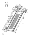
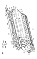
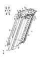
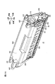
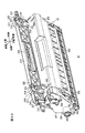
図3は、ドラムユニット26(4つの現像カートリッジ27が装着された状態)の左後上方から見た斜視図であり、図4は、ドラムユニット26(1つの現像カートリッジ27が着脱途中であり、その他の現像カートリッジ27が離脱された状態)の左前上方から見た斜視図である。また、図5は、ドラムユニット26の左側面図である。
The sheet conveyed from the fixing unit 23 is conveyed by the conveying roller 69 and the pinch roller 70 along the sheet discharge side conveying path 67 and is discharged onto the sheet discharge tray 68 by the sheet discharge roller 71.
2. Drum Unit FIG. 3 is a perspective view of the drum unit 26 (with four developing cartridges 27 mounted) as viewed from the upper left rear, and FIG. 4 shows the drum unit 26 (one developing cartridge 27 is in the process of being attached and detached). FIG. 7 is a perspective view of the developing cartridge 27 as viewed from the upper left front. FIG. 5 is a left side view of the drum unit 26.

ドラムユニット26は、各色に対応する4つのドラムサブユニット28と、前後方向に沿って並列に配設される4つのドラムサブユニット28の前後方向両側に配置されるフロントビーム101およびリヤビーム102と、フロントビーム101、4つのドラムサブユニット28およびリヤビーム102を、幅方向(左右方向)の両側から挟む1対の側板103とを備えている。   The drum unit 26 includes four drum subunits 28 corresponding to each color, a front beam 101 and a rear beam 102 disposed on both sides in the front-rear direction of the four drum subunits 28 disposed in parallel along the front-rear direction, A beam 101, four drum subunits 28, and a rear beam 102 are provided with a pair of side plates 103 that sandwich both sides in the width direction (left-right direction).

ドラムユニット26は、4つのドラムサブユニット28、フロントビーム101、リヤビーム102および1対の側板103が一体となって、本体ケーシング2内のドラム収容空間7(図1参照)に対してスライド自在に着脱される。
(1)ドラムサブユニット
ドラムサブユニット28は、図4に示すように、幅方向において間隔を隔てて対向配置される1対のサイドフレーム104と、両サイドフレーム104の間において幅方向に沿って架設されるセンタフレーム105(図2参照)とを備えている。
The drum unit 26 includes four drum subunits 28, a front beam 101, a rear beam 102, and a pair of side plates 103, and is detachably attached to the drum housing space 7 (see FIG. 1) in the main body casing 2. Is done.
(1) Drum Subunit As shown in FIG. 4, the drum subunit 28 includes a pair of side frames 104 arranged to face each other with a gap in the width direction, and the width between the side frames 104 along the width direction. A center frame 105 (see FIG. 2) is provided.

各サイドフレーム104は、樹脂材料を用いて、平板状に形成されている。各サイドフレーム104には、感光ドラム29のドラム軸33が挿通されている。
各サイドフレーム104には、現像カートリッジ27のドラムサブユニット28に対する着脱を案内するためのガイド溝106が形成されている。このガイド溝106は、サイドフレーム104の後側上端縁から、サイドフレーム104の前側下端近傍まで、略上下方向に沿って形成されており、その下端部(最深部)は、現像ローラ39が感光ドラム29に接触する位置における現像ローラ軸51の位置に対応して配置されている。ガイド溝106には、後述するカラー部材205がスライド自在に受け入れられる。
Each side frame 104 is formed in a flat plate shape using a resin material. The drum shaft 33 of the photosensitive drum 29 is inserted into each side frame 104.
Each side frame 104 is formed with a guide groove 106 for guiding attachment / detachment of the developing cartridge 27 with respect to the drum subunit 28. The guide groove 106 is formed along a substantially vertical direction from the rear upper end edge of the side frame 104 to the vicinity of the front lower end of the side frame 104, and the developing roller 39 is exposed to the lower end portion (the deepest portion). It is arranged corresponding to the position of the developing roller shaft 51 at a position in contact with the drum 29. A collar member 205 described later is slidably received in the guide groove 106.

また、各サイドフレーム104には、ボス107が形成されている。このボス107は、サイドフレーム104から幅方向外方へ突出する円筒状に形成され、現像カートリッジ27がドラムサブユニット28に装着された状態で、現像カートリッジ27の後述する窓206が幅方向において対向するように配置されている。
また、左側のサイドフレーム104には、現像カートリッジ27の後述するカップリング受動ギヤ208が幅方向において対向するカップリング内側挿通孔109が形成されている。このカップリング内側挿通孔109は、左側のサイドフレーム104の厚さ方向を貫通する丸穴として形成されている。
Each side frame 104 is formed with a boss 107. The boss 107 is formed in a cylindrical shape projecting outward in the width direction from the side frame 104, and a window 206 (to be described later) of the developing cartridge 27 is opposed in the width direction in a state where the developing cartridge 27 is mounted on the drum subunit 28. Are arranged to be.
In addition, a coupling inner insertion hole 109 is formed in the left side frame 104 so that a coupling passive gear 208 (described later) of the developing cartridge 27 faces in the width direction. The coupling inner insertion hole 109 is formed as a round hole penetrating the thickness direction of the left side frame 104.

センタフレーム105は、樹脂材料を用いて形成されている。このセンタフレーム105の上端部の幅方向両端部には、現像カートリッジ27を支持するための支持ローラ110が設けられている。支持ローラ110は、センタフレーム105の上端部に沿って幅方向に延びる回転軸(図示せず)に回転自在に支持されている。
(2)フロントビーム
フロントビーム101は、樹脂材料を用いて一体的に成形され、前後方向に沿って並列に配設される4つのドラムサブユニット28の前側に配置され、1対の側板103間に架設されている。
The center frame 105 is formed using a resin material. Support rollers 110 for supporting the developing cartridge 27 are provided at both ends in the width direction of the upper end portion of the center frame 105. The support roller 110 is rotatably supported by a rotation shaft (not shown) extending in the width direction along the upper end portion of the center frame 105.
(2) Front beam The front beam 101 is integrally formed using a resin material, and is arranged on the front side of the four drum subunits 28 arranged in parallel along the front-rear direction. It is built in.

このフロントビーム101は、幅方向中央に取り付けられる手前側把持部111と、手前側把持部111を回転自在に支持する支持軸112とを備えている。
手前側把持部111は、略U字状をなし、幅方向中央において、各遊端部が支持軸112に回動可能に支持されて、フロントビーム101に沿って起立する収納位置(図3参照)と、フロントビーム101の前側に傾倒する操作位置(図4参照)とに揺動可能に設けられている。
The front beam 101 includes a front side grip portion 111 attached to the center in the width direction and a support shaft 112 that rotatably supports the front side grip portion 111.
The front side grip portion 111 is substantially U-shaped, and at the center in the width direction, each free end portion is rotatably supported by the support shaft 112 and is stowed along the front beam 101 (see FIG. 3). ) And an operation position (see FIG. 4) tilting forward of the front beam 101 so as to be swingable.

支持軸112は、フロントビーム101を幅方向に沿って貫通するように配置され、フロントビーム101に支持されている。また、支持軸112の幅方向両端部は、フロントビーム101から幅方向外方に突出し、さらに側板103を貫通して幅方向外方に突出している。
(3)リヤビーム
リヤビーム102は、樹脂材料を用いて一体的に成形され、前後方向に沿って並列に配設される4つのドラムサブユニット28の後側に配置され、1対の側板103間に架設されている。
The support shaft 112 is disposed so as to penetrate the front beam 101 along the width direction, and is supported by the front beam 101. Further, both end portions in the width direction of the support shaft 112 protrude outward in the width direction from the front beam 101, and further protrude outward in the width direction through the side plate 103.
(3) Rear beam The rear beam 102 is integrally formed using a resin material, and is arranged on the rear side of the four drum subunits 28 arranged in parallel along the front-rear direction. It is erected.

このリヤビーム102は、図3に示すように、後方が開放される平面視略コ字状に形成されており、その幅方向中央において、奥側把持部113が一体的に設けられている。奥側把持部113は、背面視略U字状をなし、その各遊端部がリヤビーム102に連結され、後側下方から前側上方に傾斜して、リヤビーム102から斜め上方に突出するように設けられている。
(4)側板
各側板103は、各ドラムサブユニット23、フロントビーム101およびリヤビーム102を形成する樹脂材料よりも剛性の高い材料、たとえば、金属または繊維強化樹脂から形成されており、好ましくは、鋼板から形成されている。
As shown in FIG. 3, the rear beam 102 is formed in a substantially U-shape in plan view with the rear opened, and a back side grip 113 is integrally provided at the center in the width direction. The rear side grip 113 is substantially U-shaped when viewed from the back, and each free end thereof is connected to the rear beam 102 and is provided so as to incline from the rear lower side to the front upper side and to project obliquely upward from the rear beam 102. It has been.
(4) Side plate Each side plate 103 is made of a material having higher rigidity than the resin material forming each drum subunit 23, front beam 101 and rear beam 102, for example, a metal or fiber reinforced resin, preferably a steel plate. Formed from.

各側板103は、前後方向に延びる側面視略細長矩形板状をなし、前後方向に沿って並列的に配置されるフロントビーム101、4つのドラムサブユニット28およびリヤビーム102に対して、前端部がフロントビーム101に対向し、後端部がリヤビーム102に対向するように形成され、これらに固定されている。
各側板103の上端部は、断面L字状となるように、幅方向外側に屈曲され、前後方向にわたって幅方向外側に延びる鍔部114が形成されている。この鍔部114は、前後方向(水平方向)に沿って一直線上に延びている。
Each side plate 103 has a substantially elongated rectangular plate shape in side view extending in the front-rear direction, and has a front end portion with respect to the front beam 101, the four drum subunits 28, and the rear beam 102 arranged in parallel along the front-rear direction. It is formed so as to face the front beam 101 and its rear end face the rear beam 102, and is fixed to these.
An upper end portion of each side plate 103 is bent outward in the width direction so as to have an L-shaped cross section, and a flange portion 114 is formed extending outward in the width direction over the front-rear direction. The flange 114 extends in a straight line along the front-rear direction (horizontal direction).

また、各側板103の後端部は、その上端部が後方に延びる側面視略L字状に形成されており、その後方に延びる部分には、2つのころ部材118が回転自在に備えられている。この2つのころ部材118は、前後方向において、スペーサ119を挟んで配置されている。前側のころ部材118は、鍔部114の下方に配置されており、後側のころ部材118は、鍔部114の後端部の後方に配置されている。   In addition, the rear end portion of each side plate 103 is formed in a substantially L shape in a side view when the upper end portion extends rearward, and two roller members 118 are rotatably provided in a portion extending rearward. Yes. The two roller members 118 are arranged with the spacer 119 interposed therebetween in the front-rear direction. The front roller member 118 is disposed below the flange 114, and the rear roller member 118 is disposed behind the rear end of the flange 114.

さらに、各側板103の後端部には、その後端縁から側面視略U字状に切り欠いた形状の切欠部120が形成されている。この切欠部120には、ドラムユニット26が本体ケーシング2に装着された状態で、本体ケーシング2内に配置される位置決め軸(図示せず)が嵌合し、これによって、ドラムユニット26が本体ケーシング2に対して位置決めされる。   Furthermore, a notch 120 having a shape that is cut out from the rear edge in a substantially U shape in a side view is formed at the rear end of each side plate 103. The notch 120 is fitted with a positioning shaft (not shown) disposed in the main casing 2 in a state where the drum unit 26 is mounted on the main casing 2, whereby the drum unit 26 is fitted to the main casing 2. Positioned against.

また、各側板103には、上端部において、各ドラムサブユニット28のボス107を受け入れる4つの光透過孔115が形成されている。各光透過孔115は、側板103の上端部において、前後方向に沿って互いに間隔を隔てて4つ形成されている。この光透過孔115は、各ドラムサブユニット28のボス107と幅方向に対向する位置において、厚さ方向を貫通する丸孔として形成されている。そして、各光透過孔115には、各ドラムサブユニット28のボス107が、各ボス107が幅方向外方へ露出するように嵌合されており、これによって、各ドラムサブユニット28の各側板103に対するドラム軸33を中心とする回動が規制されている。   Each side plate 103 is formed with four light transmission holes 115 that receive the bosses 107 of the drum subunits 28 at the upper end. Four light transmission holes 115 are formed at the upper end of the side plate 103 at intervals from each other along the front-rear direction. The light transmitting hole 115 is formed as a round hole penetrating in the thickness direction at a position facing the boss 107 of each drum subunit 28 in the width direction. In each light transmission hole 115, a boss 107 of each drum subunit 28 is fitted so that each boss 107 is exposed outward in the width direction, whereby each side plate of each drum subunit 28 is fitted. The rotation about the drum shaft 33 with respect to 103 is restricted.

また、各側板103には、下端部において、各ドラム軸33の軸方向端部を挿通する軸孔116が形成されている。
左側の側板103には、各現像カートリッジ27のカップリング受動ギヤ208が幅方向において対向するカップリング外側挿通孔117がそれぞれ形成されている。各カップリング外側挿通孔117は、側板103の上下方向中央において、前後方向に沿って互いに間隔を隔てて4つ形成されている。このカップリング外側挿通孔117は、各ドラムサブユニット28のカップリング内側挿通孔109と幅方向において対向する位置において、厚さ方向を貫通する丸孔として形成されている。
3.現像カートリッジ
図6および図7は、現像カートリッジ27の左後方から見た斜視図であり、図8および図9は、現像カートリッジ27の左前方から見た斜視図である。また、図10は、現像カートリッジ27の平面図であり、図11は、現像カートリッジ27の右側面図であり、図12は、図11に示す切断線A−Aにおける断面図である。さらに、図13および図14は、現像カートリッジ27の右側断面図である。なお、図13および図14において、供給ローラ38および現像ローラ39が簡略化して示されている。
(1)現像カートリッジ
現像カートリッジ27の現像フレーム36は、幅方向に対向する1対の側壁201と、両側壁201の上端縁間に架設される上壁202と、両側壁201の前端縁間に架設される前壁203と、両側壁201の後端縁間に架設される後壁204とを一体的に備えており、両側壁201、前壁203および後壁204の下端縁によって、現像ローラ39を露出させる開口部41が形成されている。
Further, each side plate 103 is formed with a shaft hole 116 through which the axial end of each drum shaft 33 is inserted at the lower end.
Coupling outer insertion holes 117 are formed in the left side plate 103 so that the coupling passive gears 208 of the developing cartridges 27 face each other in the width direction. Four coupling outer insertion holes 117 are formed at the center in the vertical direction of the side plate 103 and spaced from each other along the front-rear direction. The coupling outer insertion hole 117 is formed as a round hole penetrating in the thickness direction at a position facing the coupling inner insertion hole 109 of each drum subunit 28 in the width direction.
3. 6 and 7 are perspective views of the developing cartridge 27 as viewed from the left rear, and FIGS. 8 and 9 are perspective views of the developing cartridge 27 as viewed from the left front. 10 is a plan view of the developing cartridge 27, FIG. 11 is a right side view of the developing cartridge 27, and FIG. 12 is a cross-sectional view taken along a cutting line AA shown in FIG. 13 and 14 are right side cross-sectional views of the developing cartridge 27. FIG. 13 and 14, the supply roller 38 and the developing roller 39 are shown in a simplified manner.
(1) Developing Cartridge The developing frame 36 of the developing cartridge 27 includes a pair of side walls 201 facing each other in the width direction, an upper wall 202 constructed between upper end edges of both side walls 201, and front end edges of both side walls 201. A front wall 203 to be installed and a rear wall 204 to be installed between rear end edges of both side walls 201 are integrally provided, and the developing roller is formed by the lower end edges of both side walls 201, front wall 203 and rear wall 204. An opening 41 that exposes 39 is formed.

両側壁201には、トナー収容室43内に収容されているトナーの残量を検出するための窓206が埋設されている。これらの窓206は、トナー収容室43を挟んで対向配置されており、トナーの残量の検出のための光を幅方向に沿って通過させる。
左側の側壁201には、図6ないし図9に示すように、ギヤカバー207によって被覆されるギヤ機構部が設けられている。このギヤ機構部は、ギヤカバー207から露出するカップリング受動ギヤ208と、ギヤカバー207内でカップリング受動ギヤ208に噛合するギヤトレイン230(図12参照)とを備えている。
A window 206 for detecting the remaining amount of toner stored in the toner storage chamber 43 is embedded in the side walls 201. These windows 206 are arranged to face each other with the toner storage chamber 43 interposed therebetween, and allow light for detecting the remaining amount of toner to pass along the width direction.
As shown in FIGS. 6 to 9, the left side wall 201 is provided with a gear mechanism portion covered with a gear cover 207. The gear mechanism section includes a coupling passive gear 208 exposed from the gear cover 207 and a gear train 230 (see FIG. 12) that meshes with the coupling passive gear 208 in the gear cover 207.

ギヤカバー207の下端部には、円筒状のギヤ配置部209が幅方向外方へ突出して形成されており、カップリング受動ギヤ208は、そのギヤ配置部209内に配置されて、ギヤ配置部209の先端面から露出している。
カップリング受動ギヤ208には、本体ケーシング2内に設けられるカップリング軸(図示せず)が進退自在かつ相対回転不能に結合され、このカップリング軸から本体ケーシング2内に設けられるモータ(図示せず)の駆動力が入力される。
A cylindrical gear arrangement portion 209 is formed at the lower end portion of the gear cover 207 so as to protrude outward in the width direction, and the coupling passive gear 208 is arranged in the gear arrangement portion 209 and the gear arrangement portion 209. It is exposed from the front end surface.
A coupling shaft (not shown) provided in the main body casing 2 is coupled to the coupling passive gear 208 so as to be movable back and forth and not relatively rotatable. A motor (not shown) provided in the main body casing 2 from the coupling shaft. )) Is input.

ギヤトレイン230は、アジテータ37の回転軸47に固定されるアジテータ駆動ギヤ、供給ローラ38の供給ローラ軸49に固定される供給ローラ駆動ギヤ、現像ローラ39の現像ローラ軸51に固定される現像ローラ駆動ギヤなどを備えており、これらが中間ギヤなどを介してカップリング受動ギヤ208に噛合している。これにより、カップリング受動ギヤ208に入力される駆動力は、ギヤトレイン230を介して、アジテータ37、供給ローラ38および現像ローラ39に伝達される。   The gear train 230 includes an agitator driving gear fixed to the rotation shaft 47 of the agitator 37, a supply roller driving gear fixed to the supply roller shaft 49 of the supply roller 38, and a developing roller fixed to the developing roller shaft 51 of the developing roller 39. A drive gear and the like are provided, and these mesh with the coupling passive gear 208 via an intermediate gear or the like. As a result, the driving force input to the coupling passive gear 208 is transmitted to the agitator 37, the supply roller 38 and the developing roller 39 via the gear train 230.

右側の側壁201には、図11に示すように、窓206の上方に、トナー収容室43にトナーを充填するためのトナー充填口(図示せず)を閉鎖するキャップ210が配置されている。
さらに、右側の側壁201の下端部には、現像ローラ軸51の右側軸端部を回転可能に支持する軸受部材211が設けられている。図12に示すように、この軸受部材211に現像ローラ軸51の右側端部が回転可能に挿通されるとともに、その左側端部が左側の側壁201に回転可能に挿通されることにより、現像ローラ軸51は、現像フレーム36に回転可能に支持されている。現像ローラ軸51の左側端部および右側端部は、それぞれギヤカバー207および軸受部材211から幅方向外方に突出しており、各突出部分には、カラー部材205が被覆されている。
As shown in FIG. 11, a cap 210 that closes a toner filling port (not shown) for filling the toner storage chamber 43 with toner is disposed on the right side wall 201, as shown in FIG. 11.
Further, a bearing member 211 that rotatably supports the right shaft end portion of the developing roller shaft 51 is provided at the lower end portion of the right side wall 201. As shown in FIG. 12, the right end portion of the developing roller shaft 51 is rotatably inserted into the bearing member 211, and the left end portion thereof is rotatably inserted into the left side wall 201. The shaft 51 is rotatably supported by the developing frame 36. The left end portion and the right end portion of the developing roller shaft 51 protrude outward in the width direction from the gear cover 207 and the bearing member 211, respectively, and a collar member 205 is covered with each protruding portion.

また、図6ないし図9に示すように、両側壁201の上端部には、後壁204の上端部との接続部分から幅方向外方に突出する略円筒状の突出部の一例としての離間突起212が形成されている。
上壁202には、現像カートリッジ27を移動させる際に把持される押圧部材を兼ねる取っ手214が備えられている。この取っ手214は、幅方向に長い薄板状に形成されており、上壁202とほぼ直交する状態に起立する起立状態(図7および図9参照)と、起立状態より前側に傾倒して上壁202に近接する傾倒状態(図6、図8および図13参照)と、その傾倒状態よりもさらに上壁202に近接する押圧状態(図14参照)とに揺動可能に設けられている。
Further, as shown in FIGS. 6 to 9, the upper end portions of both side walls 201 are spaced apart as an example of a substantially cylindrical protruding portion that protrudes outward in the width direction from the connection portion with the upper end portion of the rear wall 204. A protrusion 212 is formed.
The upper wall 202 is provided with a handle 214 that also serves as a pressing member that is gripped when the developing cartridge 27 is moved. The handle 214 is formed in a thin plate shape that is long in the width direction, and stands in a standing state (see FIGS. 7 and 9) that stands substantially perpendicular to the upper wall 202, and tilts forward from the standing state to the upper wall. It is provided so as to be able to swing between a tilted state (see FIGS. 6, 8 and 13) close to 202 and a pressed state (see FIG. 14) closer to the upper wall 202 than the tilted state.

より具体的には、図13および図14に示すように、上壁202の後端部には、その幅方向の両端部に、上方に向けて突出する側面視略半円形状の取っ手支持部215が一体的に形成されている。取っ手支持部215には、幅方向を貫通する貫通孔229が形成されている。一方、図6および図7に示すように、取っ手214の後端部には、その幅方向の両端部に、取っ手支持部215を嵌合可能な切欠部231が形成されている。各切欠部231には、その左側面に基端部が連結された平面視略L字状の弾性変形部232が配置されている。弾性変形部232は、遊端部が切欠部231の右側面と幅方向に間隔を隔てて対向しており、この弾性変形部232の遊端部と切欠部231の右側面との間に取っ手支持部215が嵌合されている。そして、弾性変形部232の遊端部および切欠部231の右側面には、それぞれ近接する方向に支持軸233が突出して設けられており、弾性変形部232を変形させて、これらの支持軸233の間隔を広げた状態で、各切欠部231に取っ手支持部215を嵌合させ、その後、弾性変形部232の変形を解除して、各支持軸233を取っ手支持部215の貫通孔229に挿入させることによって、取っ手214が取っ手支持部215に揺動可能に取り付けられている。   More specifically, as shown in FIGS. 13 and 14, at the rear end of the upper wall 202, a handle support portion having a substantially semicircular shape in side view protruding upward at both ends in the width direction thereof. 215 is integrally formed. The handle support portion 215 is formed with a through hole 229 that penetrates in the width direction. On the other hand, as shown in FIGS. 6 and 7, notches 231 into which the handle support portions 215 can be fitted are formed at both ends in the width direction at the rear end portion of the handle 214. Each notch 231 is provided with a substantially L-shaped elastic deformation portion 232 in plan view with a base end connected to the left side surface thereof. The elastic deformation portion 232 has a free end portion opposed to the right side surface of the notch portion 231 with a gap in the width direction, and a handle between the free end portion of the elastic deformation portion 232 and the right side surface of the notch portion 231. The support part 215 is fitted. Support shafts 233 project from the free end portion of the elastic deformation portion 232 and the right side surface of the cutout portion 231 so as to approach each other, and the elastic deformation portion 232 is deformed to support these support shafts 233. The handle support portions 215 are fitted into the respective notches 231 in a state where the distance between them is widened, and then the deformation of the elastic deformation portion 232 is released, and each support shaft 233 is inserted into the through hole 229 of the handle support portion 215. As a result, the handle 214 is swingably attached to the handle support portion 215.

また、上壁202の前端部には、図9および図12に示すように、その幅方向(現像ローラ39の軸方向)の両端部に、幅方向に現像ローラ39のゴムローラ50の幅方向の長さ(軸方向の長さ)とほぼ等しい間隔を隔てて、円筒状のガイド部材の一例としてのばねガイド部材216が形成されている。各ばねガイド部材216は、各取っ手支持部215と前後方向に間隔を隔てて対向し、かつ、現像ローラ39のゴムローラ52の幅方向の両端部とそれぞれ対向している。また、各ばねガイド部材216内には、図13および図14に示すように、上下方向に進退可能な当接部材217と、この当接部材217を常に上方に向けて付勢する弾性部材の一例としてのコイルばね218とが設けられている。   Further, as shown in FIGS. 9 and 12, the front wall 202 has a front end portion in the width direction (the axial direction of the developing roller 39) and a width direction of the rubber roller 50 of the developing roller 39 in the width direction. A spring guide member 216 as an example of a cylindrical guide member is formed at an interval substantially equal to the length (length in the axial direction). Each spring guide member 216 is opposed to each handle support portion 215 with a space in the front-rear direction, and is opposed to both end portions of the developing roller 39 in the width direction of the rubber roller 52. Further, in each spring guide member 216, as shown in FIG. 13 and FIG. 14, a contact member 217 that can advance and retract in the vertical direction and an elastic member that constantly biases the contact member 217 upward. An example coil spring 218 is provided.

当接部材217は、上面が凸湾曲した平面視略円形状の本体部219と、本体部219の下面の中央部から下方に突出するボス部220と、本体部219の下面の周縁部からばねガイド部材216の内周面に沿って延びる円筒状の延部221とを一体的に備えている。そして、延部221には、複数の係止爪部222が形成されており、各係止爪部222がばねガイド部材216に形成された溝部223に嵌められ、その先端部が溝部223の上端部に係止することによって、当接部材217がばねガイド部材216から離脱しないようにされている。   The abutting member 217 has a substantially circular main body 219 with a convex upper surface, a boss 220 protruding downward from the center of the lower surface of the main body 219, and a spring from the peripheral edge of the lower surface of the main body 219. A cylindrical extension 221 extending along the inner peripheral surface of the guide member 216 is integrally provided. The extending portion 221 is formed with a plurality of locking claw portions 222, and each locking claw portion 222 is fitted into a groove portion 223 formed in the spring guide member 216, and a tip portion thereof is an upper end of the groove portion 223. The contact member 217 is prevented from being detached from the spring guide member 216 by being locked to the portion.

コイルばね218は、下端部に上壁202に形成されたばね取付ボス224が挿入され、上端部に当接部材217のボス部220が挿入されて、当接部材217と上壁202との間で圧縮された状態に設けられている。
取っ手214の下面(上壁202との対向面)には、図9に示すように、各当接部材217と対応する位置に、その対応する当接部材217を受け入れ可能な伝達部の一例としての凹部225が形成されている。取っ手214が傾倒状態に傾倒した状態では、各凹部225に各当接部材217が受け入れられて、各当接部材217の先端が各凹部225の底面(取っ手214の下面)に当接する。
The coil spring 218 has a spring mounting boss 224 formed on the upper wall 202 inserted in the lower end portion and a boss portion 220 of the contact member 217 inserted in the upper end portion between the contact member 217 and the upper wall 202. It is provided in a compressed state.
As shown in FIG. 9, on the lower surface of the handle 214 (the surface facing the upper wall 202), as an example of a transmission portion that can receive the corresponding contact member 217 at a position corresponding to each contact member 217. The recessed part 225 is formed. When the handle 214 is tilted to the tilted state, each contact member 217 is received in each recess 225, and the tip of each contact member 217 contacts the bottom surface of each recess 225 (the lower surface of the handle 214).

また、取っ手214には、図10に示すように、幅方向の中央部に、幅方向に長い平面視略矩形状の把持孔226が形成されている。これにより、把持孔226に指を入れて、取っ手214を把持することができる。
さらに、取っ手214には、その前端部における幅方向の両端部に、幅方向外方へ突出する側面視略円柱状の押圧突起227が形成されている。各押圧突起227は、図10に示すように、同じ側に突出する離間突起212の先端面を含む平面S上にその先端面が位置するような長さに形成されている。すなわち、各押圧突起227は、幅方向において、その先端面が同じ側に突出する離間突起212の先端面と同じ位置に配置されている。また、各押圧突起227は、現像カートリッジ27がドラムサブユニット28に装着され、取っ手214が傾倒状態に傾倒した状態で、図11に示すように、離間突起212よりも低い位置に配置されている。
Further, as shown in FIG. 10, the handle 214 is formed with a gripping hole 226 having a substantially rectangular shape in plan view that is long in the width direction at the center in the width direction. Thereby, the handle 214 can be gripped by putting a finger into the gripping hole 226.
Further, the handle 214 is formed with pressing protrusions 227 that are substantially cylindrical in a side view and project outward in the width direction at both ends in the width direction at the front end. As shown in FIG. 10, each pressing protrusion 227 is formed in such a length that the front end surface thereof is positioned on the plane S including the front end surface of the separation protrusion 212 protruding to the same side. That is, each pressing protrusion 227 is disposed at the same position as the distal end surface of the separation protrusion 212 whose distal end surface projects on the same side in the width direction. Each pressing protrusion 227 is disposed at a position lower than the separation protrusion 212 as shown in FIG. 11 in a state where the developing cartridge 27 is mounted on the drum subunit 28 and the handle 214 is inclined. .

前壁203には、図8および図9に示すように、幅方向の両端部に、前方に向けて突出する側面視略台形状の被支持突起228が形成されている。
(2)現像カートリッジのドラムユニットに対する着脱
各色に対応する現像カートリッジ27は、取っ手214の把持孔226に指を入れて、取っ手214を把持し、図4に示すように、ドラムユニット26の上方から、その現像カートリッジ27に対応するドラムサブユニット28へ装着する。
As shown in FIGS. 8 and 9, the front wall 203 is formed with supported protrusions 228 having a substantially trapezoidal shape in a side view projecting forward at both ends in the width direction.
(2) Attaching / detaching the developing cartridge to / from the drum unit The developing cartridge 27 corresponding to each color puts a finger into the holding hole 226 of the handle 214 to hold the handle 214, and as shown in FIG. A drum subunit 28 corresponding to the developing cartridge 27 is mounted.

より具体的には、現像カートリッジ27の現像ローラ軸51の軸方向両端部のカラー部材205を、対応するドラムサブユニット28の各サイドフレーム104のガイド溝106に挿入し、そのガイド溝106に沿って、現像カートリッジ27をドラムサブユニット28に対して下方へ押し込む。現像ローラ39が感光ドラム29に接触すると、それ以上の現像カートリッジ27の押し込みが規制される。そして、現像カートリッジ27の自重により、現像カートリッジ27が現像ローラ軸51を中心に、その上端部が前側のセンタフレーム105にもたれ掛かる方向に倒れ、現像フレーム36の前壁203に形成されている各被支持突起228が、センタフレーム105の支持ローラ110に当接して支持される。これによって、現像カートリッジ27がドラムサブユニット28に対して位置決めされ、その現像カートリッジ27のドラムサブユニット28に対する装着が達成される。   More specifically, the collar members 205 at both ends in the axial direction of the developing roller shaft 51 of the developing cartridge 27 are inserted into the guide grooves 106 of the corresponding side frames 104 of the corresponding drum subunit 28, and along the guide grooves 106. Then, the developing cartridge 27 is pushed downward with respect to the drum subunit 28. When the developing roller 39 comes into contact with the photosensitive drum 29, further pressing of the developing cartridge 27 is restricted. Then, due to the weight of the developing cartridge 27, the developing cartridge 27 falls about the developing roller shaft 51 with its upper end portion leaning against the front center frame 105, and is formed on the front wall 203 of the developing frame 36. The supported protrusion 228 is supported in contact with the support roller 110 of the center frame 105. As a result, the developing cartridge 27 is positioned with respect to the drum subunit 28, and the mounting of the developing cartridge 27 to the drum subunit 28 is achieved.

こうして現像カートリッジ27が装着された後、起立状態の取っ手214から手が放されると、取っ手214は、自重により、支持軸233を支点として起立状態から傾倒状態へ傾倒する。
そして、すべての現像カートリッジ27がドラムサブユニット28へ装着されると、図3に示すように、フロントビーム101の手前側把持部111と、各現像カートリッジ27の取っ手214と、リヤビーム102の奥側把持部113とが、前後方向に沿って重なるように配置される。
After the developing cartridge 27 is mounted in this manner, when the hand is released from the handle 214 in the standing state, the handle 214 is tilted from the standing state to the tilted state with the support shaft 233 as a fulcrum by its own weight.
When all the developing cartridges 27 are attached to the drum subunit 28, as shown in FIG. 3, the front side grip portion 111 of the front beam 101, the handle 214 of each developing cartridge 27, and the rear side of the rear beam 102 The grip portion 113 is disposed so as to overlap along the front-rear direction.

一方、現像カートリッジ27がドラムユニット26(ドラムサブユニット28)に装着された状態で、取っ手214を把持して、取っ手214を傾倒状態から起立状態へ引き起こし、上方に持ち上げることにより、現像カートリッジ27をドラムユニット26から離脱させることができる。
4.レール・離間押圧機構
図15は、本体ケーシング2およびドラムユニット26の右前上方から見た斜視図であり、本体ケーシング2の外装板およびフロントカバー9が取り外され、その本体ケーシング2にドラムユニット26が装着された状態を示している。
On the other hand, in a state where the developing cartridge 27 is mounted on the drum unit 26 (drum subunit 28), the handle 214 is gripped, the handle 214 is raised from the tilted state to the standing state, and lifted upward, whereby the developing cartridge 27 is removed from the drum unit. 26 can be detached.
4). FIG. 15 is a perspective view of the main body casing 2 and the drum unit 26 as seen from the upper right front. The exterior plate of the main body casing 2 and the front cover 9 are removed, and the drum unit 26 is attached to the main body casing 2. Shows the state.

本体ケーシング2は、ドラムユニット26を挟んで幅方向に対向配置される1対の本体フレーム301を備えており、各本体フレーム301の内側面には、ドラムユニット26の着脱を案内するためのレール302と、ドラムユニット26に装着された現像カートリッジ27の現像ローラ39を感光ドラム29に対して離間および押圧するための離間押圧機構303とを備えている。   The main body casing 2 includes a pair of main body frames 301 that are opposed to each other in the width direction across the drum unit 26, and a rail 302 for guiding attachment / detachment of the drum unit 26 and an inner surface of each main body frame 301. A separation pressing mechanism 303 for separating and pressing the developing roller 39 of the developing cartridge 27 mounted on the drum unit 26 against the photosensitive drum 29 is provided.

なお、図15では、左側の離間押圧機構303のみが示されている。
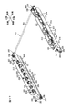
図16は、ドラムユニット26ならびに左右のレール302および離間押圧機構303の右前上方から見た斜視図である。また、図17は、左右のレール302および離間押圧機構303の右前上方から見た斜視図である。
(1)レール
左右のレール302は、ドラムユニット26を挟んで幅方向に対向配置されている。各レール302は、本体フレーム301の前端面に対向配置されるレール固定部304と、本体フレーム301の内側面に沿って前後方向(水平方向)に延びるレール本体部305と、レール固定部304とレール本体部305とを連結する連結部306とを一体的に備えている。
In FIG. 15, only the left side separation pressing mechanism 303 is shown.
FIG. 16 is a perspective view of the drum unit 26 and the left and right rails 302 and the separation pressing mechanism 303 as seen from the upper right front. FIG. 17 is a perspective view of the left and right rails 302 and the separation pressing mechanism 303 as seen from the upper right front.
(1) Rails The left and right rails 302 are opposed to each other in the width direction with the drum unit 26 interposed therebetween. Each rail 302 includes a rail fixing portion 304 disposed to face the front end surface of the main body frame 301, a rail main body portion 305 extending in the front-rear direction (horizontal direction) along the inner side surface of the main body frame 301, and a rail fixing portion 304, A connecting portion 306 that connects the rail main body portion 305 is integrally provided.

レール固定部304は、ねじ307によって、本体フレーム301の前端面に固定されている。
レール本体部305は、下端部が幅方向内方に向けて屈曲された断面略L字状に形成されており、水平に延びる部分には、ドラムユニット26が本体ケーシング2に装着された状態で、ドラムユニット26の各側板103の鍔部114が載置される。
The rail fixing portion 304 is fixed to the front end surface of the main body frame 301 by screws 307.
The rail main body 305 is formed in a substantially L-shaped cross section with its lower end bent toward the inner side in the width direction, and the drum unit 26 is mounted on the main casing 2 in a horizontally extending portion. The flanges 114 of the side plates 103 of the drum unit 26 are placed.

連結部306は、レール固定部304の幅方向内側の端縁とレール本体部305の前端縁とを連結するように形成されている。この連結部306には、コロ支持軸308が幅方向に貫通して支持されており、連結部306の幅方向内面には、そのコロ支持軸308に回動可能に支持されたレールころ309が対向配置されている。レールころ309の周面の最上端部分は、レール本体部305の下端部(水平に延びる部分)よりも上方に位置している。
(2)ドラムユニットの本体ケーシングに対する装着
ドラムユニット26を本体ケーシング2に装着するには、まず、ドラムユニット26の手前側把持部111および奥側把持部113(図3参照)を両手でそれぞれ把持して、ドラムユニット26を持ち上げる。そして、図1が参照されるように、フロントカバー9を傾倒させて、着脱口8を開放し、この着脱口8からドラム収容空間7に向けて、ドラムユニット26を進入させる。
The connecting portion 306 is formed so as to connect the end edge on the inner side in the width direction of the rail fixing portion 304 and the front end edge of the rail main body portion 305. The connecting portion 306 supports a roller support shaft 308 penetrating in the width direction. Rail rollers 309 rotatably supported by the roller supporting shaft 308 are provided on the inner surface of the connecting portion 306 in the width direction. Opposed. The uppermost end portion of the peripheral surface of the rail roller 309 is located above the lower end portion (a portion extending horizontally) of the rail body portion 305.
(2) Mounting of drum unit to main body casing In order to mount the drum unit 26 to the main body casing 2, first, the front side grip portion 111 and the back side grip portion 113 (see FIG. 3) of the drum unit 26 are respectively gripped with both hands, The drum unit 26 is lifted. Then, as shown in FIG. 1, the front cover 9 is tilted to open the attachment / detachment opening 8, and the drum unit 26 enters from the attachment / detachment opening 8 toward the drum housing space 7.

このとき、ドラムユニット26の後端部に設けられる各ころ部材118を、レール302のレール本体部305上を転動させる。また、奥側把持部113から手を放して、ドラムユニット26の両鍔部114をそれぞれ左右のレールころ309上に載せる。この状態でドラムユニット26を後方に向けて押すと、各ころ部材118がレール本体部305上を転動するとともに、各レールころ309上を鍔部114が滑動し、これによりドラムユニット26が円滑に移動する。また、各現像カートリッジ27の離間突起212および押圧突起227が、後述するホルダ固定部322のカム収容部323上を摺動する。   At this time, each roller member 118 provided at the rear end portion of the drum unit 26 rolls on the rail main body 305 of the rail 302. Also, let go of the back side gripping part 113 and place the both flanges 114 of the drum unit 26 on the left and right rail rollers 309, respectively. When the drum unit 26 is pushed rearward in this state, each roller member 118 rolls on the rail main body 305, and the flange 114 slides on each rail roller 309, whereby the drum unit 26 moves smoothly. To do. Further, the separation protrusion 212 and the pressing protrusion 227 of each developing cartridge 27 slide on a cam accommodating portion 323 of a holder fixing portion 322 described later.

そして、各ころ部材118がレール302上から奥側に脱落し、各レールころ309上から鍔部114が各レールころ309の奥側に脱落して、各鍔部114がレール本体部305の水平に延びる部分上に載置されると、各現像カートリッジ27の押圧突起227および離間突起212がそれぞれ後述する押圧突起受入部325および離間突起受入部326に受け入れられて、ドラムユニット26の本体ケーシング2に対する装着が完了される。   Then, each roller member 118 is dropped from the rail 302 to the back side, the flange 114 is dropped from the rail roller 309 to the back side of each rail roller 309, and each flange 114 is horizontal to the rail body 305. Is placed on a portion extending in the direction, the pressing protrusion 227 and the separation protrusion 212 of each developing cartridge 27 are received by a pressing protrusion receiving portion 325 and a separation protrusion receiving portion 326, which will be described later, and the drum unit 26 with respect to the main body casing 2 is received. Installation is completed.

この後、手前側把持部111から手を離して、フロントカバー9を閉じて、フロントカバー9により着脱口8を閉鎖する。フロントカバー9を閉じると、これに連動して、手前側把持部111は、支持軸112を支点として、起立状態(図4参照)から収納位置(図3参照)に回動する。
(3)離間押圧機構
離間押圧機構303は、図17に示すように、1対の押圧力入力部材の一例としての直動カム部材310と、各直動カム部材310に対して設けられた中間部材311と、各直動カム部材310を前後方向に直線移動可能に保持するカムホルダ312と、1対の直動カム部材310を同期して直線移動させるための同期移動機構313とを備えている。
Thereafter, the hand is released from the front side grip portion 111, the front cover 9 is closed, and the attachment / detachment opening 8 is closed by the front cover 9. When the front cover 9 is closed, the front gripping portion 111 is rotated from the standing state (see FIG. 4) to the storage position (see FIG. 3) with the support shaft 112 as a fulcrum in conjunction with this.
(3) Separation Press Mechanism As shown in FIG. 17, the separation press mechanism 303 is a linear cam member 310 as an example of a pair of pressing force input members, and an intermediate provided for each linear cam member 310. A member 311, a cam holder 312 that holds each linear cam member 310 so as to be linearly movable in the front-rear direction, and a synchronous movement mechanism 313 that linearly moves the pair of linear cam members 310 synchronously. .

図18は、直動カム部材310、中間部材311および同期移動機構313の右前上方から見た斜視図である。すなわち、この図18には、カムホルダ312の図示を省略して、離間押圧機構303の右前上方から見た斜視図が示されている。また、図19は、直動カム部材310および中間部材311の動きを説明するための斜視図である。さらに、図20は、図19(a)の状態における直動カム部材310および中間部材311の右側面図であり、図21は、図19(c)の状態における直動カム部材310および中間部材311の右側面図であり、図22は、図19(e)の状態における直動カム部材310および中間部材311の右側面図である。   FIG. 18 is a perspective view of the linear cam member 310, the intermediate member 311 and the synchronous movement mechanism 313 as seen from the upper right front. That is, FIG. 18 is a perspective view of the separating and pressing mechanism 303 as viewed from the upper right front side with the cam holder 312 omitted. FIG. 19 is a perspective view for explaining the movement of the linear cam member 310 and the intermediate member 311. Further, FIG. 20 is a right side view of the linear cam member 310 and the intermediate member 311 in the state of FIG. 19A, and FIG. 21 is a linear cam member 310 and the intermediate member in the state of FIG. 311 is a right side view, and FIG. 22 is a right side view of the linear cam member 310 and the intermediate member 311 in the state of FIG.

直動カム部材310は、本体フレーム301(図15参照)の内側面に沿って前後方向に延びる薄板状のカム本体板314と、カム本体板314の幅方向の内側面に設けられた4つの操作部材315とを備えている。
カム本体板314には、前後方向に等間隔を隔てて、前後方向に長い略矩形状の矩形孔316が4つ形成されている。
The linear cam member 310 includes a thin plate-like cam main body plate 314 extending in the front-rear direction along the inner surface of the main body frame 301 (see FIG. 15), and four provided on the inner surface in the width direction of the cam main body plate 314. And an operation member 315.
The cam body plate 314 is formed with four substantially rectangular holes 316 that are long in the front-rear direction and are equally spaced in the front-rear direction.

4つの操作部材315は、4つの矩形孔316のそれぞれ前側に配置されている。各操作部材315は、側面視クランク形状に形成され、カム本体板314の上端縁に沿って延び、現像カートリッジ27の押圧突起227を下方に押圧するための押圧作用部317と、カム本体板314の下端縁に沿って延び、後述するように中間部材311を回動させるための接離作用部318と、押圧作用部317の後端部と接離作用部318の前端部とを連結する連結部319とを一体的に備えている。   The four operation members 315 are disposed on the front side of the four rectangular holes 316, respectively. Each operation member 315 is formed in a crank shape in a side view, extends along the upper end edge of the cam main body plate 314, a pressing action portion 317 for pressing the pressing protrusion 227 of the developing cartridge 27 downward, and the cam main body plate 314. As shown later, the contact / separation action part 318 for rotating the intermediate member 311, and the connection for connecting the rear end part of the pressing action part 317 and the front end part of the contact / separation action part 318 are extended. The unit 319 is integrally provided.

接離作用部318の後端部には、図20ないし図22に示すように、上方に突出する突起状の突起部320が形成されている。
また、最前の操作部材315は、それ以外の3つの操作部材315(以下「後側3つの操作部材315」という。)と形状が異なる。すなわち、最前の操作部材315の押圧作用部317は、後側3つの操作部材315の押圧作用部317と比較して、その前後方向の長さが長く形成されている。また、最前の操作部材315の接離作用部318は、後側3つの操作部材315の接離作用部318と比較して、その前後方向の長さが短く形成されている。このような形状(寸法)の違いにより、後述するように、すべての現像カートリッジ27の現像ローラ39を感光ドラム29に押圧させたり、ブラック現像カートリッジ27Kの現像ローラ39のみを感光ドラム29に押圧させたり、すべての現像カートリッジ27の現像ローラ39を感光ドラム29から離間させたりすることができる。
As shown in FIGS. 20 to 22, a protruding projection 320 protruding upward is formed at the rear end of the contact / separation operating portion 318.
Further, the foremost operating member 315 has a different shape from the other three operating members 315 (hereinafter referred to as “the rear three operating members 315”). That is, the pressing action part 317 of the foremost operation member 315 is formed to have a longer length in the front-rear direction than the pressing action parts 317 of the three rear operation members 315. Further, the contact / separation operating portion 318 of the foremost operation member 315 is formed to have a shorter length in the front-rear direction than the contact / separation operation portions 318 of the three rear operation members 315. Due to the difference in shape (dimension), as will be described later, the developing rollers 39 of all the developing cartridges 27 are pressed against the photosensitive drum 29, or only the developing roller 39 of the black developing cartridge 27K is pressed against the photosensitive drum 29. Or the developing rollers 39 of all the developing cartridges 27 can be separated from the photosensitive drum 29.

4つの中間部材311は、4つの操作部材315にそれぞれ後側に配置されて、4つの矩形孔316にそれぞれ幅方向に対向している。各中間部材311は、図20ないし図22に示すように、側面視略L字状をなし、幅方向に厚みを有するブロック状に形成されている。各中間部材311の一端部には、中間部材支持軸321が幅方向に貫通しており、中間部材311は、この中間部材支持軸321に回動可能に支持されている。各中間部材311は、接離作用部318と非接触の状態(図20参照)で、下端部が接離作用部318の突起部320と前後方向に間隔を隔てて対向している。   The four intermediate members 311 are respectively arranged on the rear side of the four operation members 315 and face the four rectangular holes 316 in the width direction. As shown in FIGS. 20 to 22, each intermediate member 311 has a substantially L shape in a side view and is formed in a block shape having a thickness in the width direction. An intermediate member support shaft 321 passes through one end portion of each intermediate member 311 in the width direction, and the intermediate member 311 is rotatably supported by the intermediate member support shaft 321. Each intermediate member 311 is in a non-contact state with the contact / separation action part 318 (see FIG. 20), and the lower end part faces the protrusion 320 of the contact / separation action part 318 with a space in the front-rear direction.

中間部材支持軸321は、図18に示すように、前後方向において互いに等間隔(4つの現像カートリッジ27がドラムユニット26に装着された状態での各離間突起212間の間隔と等しい間隔)を隔てて配置されている。各中間部材支持軸321は、これに支持される中間部材311が対向する矩形孔316に挿通されて、カム本体板314の幅方向外方に延び、その幅方向の内側端部がカムホルダ312に回転不能に支持されている。   As shown in FIG. 18, the intermediate member support shafts 321 are spaced from each other at equal intervals in the front-rear direction (same intervals as the intervals between the separation protrusions 212 when the four developing cartridges 27 are mounted on the drum unit 26). Has been placed. Each intermediate member support shaft 321 is inserted into a rectangular hole 316 opposed to the intermediate member 311 supported by the intermediate member support shaft 321 and extends outward in the width direction of the cam main body plate 314, and the inner end portion in the width direction is connected to the cam holder 312. It is supported so that it cannot rotate.

カムホルダ312は、図17に示すように、本体フレーム301の内側面に沿って前後方向に延びる薄板状のホルダ固定部322と、このホルダ固定部322の下端縁に連続するカム収容部323とを一体的に備えている。
ホルダ固定部322は、ねじ324によって、本体フレーム301の内側面に固定されている。
As shown in FIG. 17, the cam holder 312 includes a thin plate-like holder fixing portion 322 extending in the front-rear direction along the inner surface of the main body frame 301, and a cam housing portion 323 continuous with the lower end edge of the holder fixing portion 322. Integrated.
The holder fixing portion 322 is fixed to the inner side surface of the main body frame 301 by screws 324.

カム収容部323は、ホルダ固定部322の下端縁の全長から幅方向の内方へ延び、下方へ屈曲し、さらに幅方向の外方へ屈曲する、断面略コ字状に形成されている。カム収容部323には、その上面から幅方向の内側面に連続して切り欠くことによって、現像カートリッジ27の押圧突起227を受入可能な押圧突起受入部325と、現像カートリッジ27の離間突起212を受入可能な離間突起受入部326とが、交互に、それぞれ4つずつ形成されている。すなわち、カム収容部323には、4つの押圧突起受入部326が、前後方向において、各現像カートリッジ27がドラムユニット26に装着された状態での各押圧突起227間の間隔と等しい間隔を隔てて形成されている。また、4つの離間突起受入部326が、前後方向において、各現像カートリッジ27がドラムユニット26に装着された状態での各離間突起212間の間隔と等しい間隔を隔てて形成されている。各離間突起受入部326は、各押圧突起受入部325の後方に配置されている。各離間突起受入部326に離間突起212が受け入れられた状態で、各離間突起212は、各中間部材311に対して上方から対向する。   The cam accommodating portion 323 is formed in a substantially U-shaped cross section that extends inward in the width direction from the entire length of the lower end edge of the holder fixing portion 322, bends downward, and further bends outward in the width direction. The cam housing portion 323 has a pressing protrusion receiving portion 325 that can receive the pressing protrusion 227 of the developing cartridge 27 and a separation protrusion 212 of the developing cartridge 27 by continuously cutting from the upper surface to the inner surface in the width direction. Four separate protrusion receiving portions 326 that can be received are formed alternately. That is, four pressing protrusion receiving portions 326 are formed in the cam housing portion 323 at intervals equal to the interval between the pressing protrusions 227 when the developing cartridges 27 are mounted on the drum unit 26 in the front-rear direction. Has been. In addition, four spacing protrusion receiving portions 326 are formed in the front-rear direction at intervals equal to the spacing between the spacing protrusions 212 in a state where each developing cartridge 27 is mounted on the drum unit 26. Each spacing protrusion receiving portion 326 is disposed behind each pressing protrusion receiving portion 325. In a state where the separation protrusions 212 are received by the separation protrusion receiving portions 326, the separation protrusions 212 face the intermediate members 311 from above.

同期移動機構313は、左側の直動カム部材310の直線移動に伴って、その左側の直動カム部材310から右側の直動カム部材310に直線移動のための駆動力を伝達する構成になっている。
すなわち、同期移動機構313は、図18に示すように、左側の直動カム部材310の後端部の上面に形成された左側ラックギヤ327と、この左側ラックギヤ327と噛合する左側ピニオンギヤ328と、右側の直動カム部材310の後端部の上面に形成された右側ラックギヤ329と、この右側ラックギヤ329と噛合する右側ピニオンギヤ330と、左側ピニオンギヤ328および右側ピニオンギヤ330が相対回転不能に取り付けられる連結軸331とを備えている。
The synchronous movement mechanism 313 is configured to transmit a driving force for linear movement from the left linear cam member 310 to the right linear cam member 310 in accordance with the linear movement of the left linear cam member 310. ing.
That is, as shown in FIG. 18, the synchronous movement mechanism 313 includes a left rack gear 327 formed on the upper surface of the rear end portion of the left linear cam member 310, a left pinion gear 328 meshing with the left rack gear 327, The right rack gear 329 formed on the upper surface of the rear end of the linear cam member 310, the right pinion gear 330 meshing with the right rack gear 329, and the connecting shaft 331 to which the left pinion gear 328 and the right pinion gear 330 are attached so as not to be relatively rotatable. And.

また、左側の直動カム部材310には、カム本体板314の幅方向の外側面に、図示しないモータの駆動力が入力される入力ラックギヤ332が設けられている。
(4)離間押圧動作
図19ないし図22を主に参照して、離間押圧機構303の動作を説明する。
図19(a)および図20に示すように、直動カム部材310が最前方位置に移動されている状態では、各操作部材315の接離作用部318とそれらの各後方に配置される中間部材311とが、前後方向に間隔を隔てた非接触状態で対向している。最前の操作部材315の接離作用部318とその後方に配置される中間部材311との間には、後側3つの操作部材315の接離作用部318とそれらの各後方に配置される中間部材311との間の間隔よりも大きな間隔が形成されている。
The left linear cam member 310 is provided with an input rack gear 332 to which a driving force of a motor (not shown) is input on the outer surface in the width direction of the cam body plate 314.
(4) Separation Pressing Operation The operation of the separation pressing mechanism 303 will be described mainly with reference to FIGS. 19 to 22.
As shown in FIGS. 19A and 20, in the state where the linear cam member 310 is moved to the foremost position, the contact / separation operating portion 318 of each operation member 315 and the middle disposed at the rear thereof. The member 311 is opposed to the member 311 in a non-contact state with an interval in the front-rear direction. Between the contact / separation action part 318 of the foremost operation member 315 and the intermediate member 311 arranged behind it, the contact / separation action part 318 of the rear three operation members 315 and intermediate positions arranged behind them. An interval larger than the interval between the members 311 is formed.

この状態では、各現像カートリッジ27が、現像ローラ39と感光ドラム29とが接触する接触位置に配置されている。そして、各操作部材315の押圧作用部317が、各現像カートリッジ27の押圧突起227に上方から当接して、各押圧突起227を下方に向けて押圧している。各押圧突起227が下方に押圧されることにより、各現像カートリッジ27において、図14に示すように、取っ手214が支持軸233を支点に回動して押圧状態となり、取っ手214(凹部225)によって当接部材217が押し下げられて、コイルばね218が収縮されている。そして、その収縮によるコイルばね218の付勢力が現像フレーム36の上壁202に入力され、現像フレーム36が下方に向けて付勢されることにより、現像ローラ39が感光ドラム29に押圧されている。このとき、コイルばね218は、1N以上20N以下の付勢力を発生する。   In this state, each developing cartridge 27 is disposed at a contact position where the developing roller 39 and the photosensitive drum 29 are in contact with each other. The pressing action portion 317 of each operation member 315 is in contact with the pressing protrusion 227 of each developing cartridge 27 from above and presses each pressing protrusion 227 downward. When each pressing protrusion 227 is pressed downward, in each developing cartridge 27, as shown in FIG. 14, the handle 214 is rotated by using the support shaft 233 as a fulcrum, and is pressed by the handle 214 (recess 225). The contact member 217 is pushed down, and the coil spring 218 is contracted. The biasing force of the coil spring 218 due to the contraction is input to the upper wall 202 of the developing frame 36, and the developing frame 39 is biased downward, so that the developing roller 39 is pressed against the photosensitive drum 29. . At this time, the coil spring 218 generates a biasing force of 1N or more and 20N or less.

この状態から、図示しないモータの駆動力が入力ラックギヤ332に入力されて、左側の直動カム部材310が後方に移動されると、この左側の直動カム部材310の移動に伴って、左側ピニオンギヤ328が回転し、この左側ピニオンギヤ328の回転が連結軸331を介して右側ピニオンギヤ330に伝達され、右側ピニオンギヤ330が左側ピニオンギヤ328と同方向に回転することにより、右側の直動カム部材310が後方に移動する。   From this state, when a driving force of a motor (not shown) is input to the input rack gear 332 and the left linear cam member 310 is moved rearward, the left pinion gear is moved along with the movement of the left linear cam member 310. 328 rotates, the rotation of the left pinion gear 328 is transmitted to the right pinion gear 330 via the connecting shaft 331, and the right pinion gear 330 rotates in the same direction as the left pinion gear 328, whereby the right linear cam member 310 moves rearward. Move to.

直動カム部材310の後方への移動が進むと、後側3つの操作部材315の押圧作用部317と現像カートリッジ27の押圧突起227との係合が解除され、それらの押圧作用部317による押圧突起227の押圧が解除される。また、図19(b)に示すように、後側3つの操作部材315の接離作用部318が、それらの各後方に配置される中間部材311の下端部に当接して、各中間部材311の下端部を後方に向けて押圧し、各中間部材311が中間部材支持軸321を支点として上方に持ち上がるように回動する。これらの各中間部材311の回動の途中で、各中間部材311がそれぞれの上方に位置する離間突起212に下方から当接し、各中間部材311から離間突起212に上方向の力が付与されることによって、イエロー現像カートリッジ27Y、マゼンタ現像カートリッジ27Mおよびシアン現像カートリッジ27Cが上方に持ち上げられていく。   When the rearward movement of the linear cam member 310 advances, the engagement between the pressing action portions 317 of the three rear operation members 315 and the pressing protrusions 227 of the developing cartridge 27 is released, and the pressing action by the pressing action portions 317 is released. The pressing of the protrusion 227 is released. Further, as shown in FIG. 19B, the contact / separation action portions 318 of the three rear operation members 315 come into contact with the lower end portions of the intermediate members 311 arranged at the rear thereof, and each intermediate member 311. The intermediate member 311 rotates so as to be lifted upward with the intermediate member support shaft 321 as a fulcrum. In the middle of the rotation of each intermediate member 311, each intermediate member 311 comes into contact with the separation protrusion 212 positioned above from below, and an upward force is applied from each intermediate member 311 to the separation protrusion 212. As a result, the yellow developing cartridge 27Y, the magenta developing cartridge 27M, and the cyan developing cartridge 27C are lifted upward.

そして、直動カム部材310の後方への移動がさらに進み、図19(c)および図21に示すように、後側3つの操作部材315の接離作用部318の上面に中間部材311の一端部(中間部材支持軸321が挿通されている側の端部)が当接すると、イエロー現像カートリッジ27Y、マゼンタ現像カートリッジ27Mおよびシアン現像カートリッジ27Cが離間位置に配置され、イエロー現像カートリッジ27Y、マゼンタ現像カートリッジ27Mおよびシアン現像カートリッジ27Cの現像ローラ39が感光ドラム29から離間する。このとき、ブラック現像カートリッジ27Kの押圧突起227は、操作部材315の押圧作用部317により押圧されている。これにより、ブラック現像カートリッジ27Kの現像ローラ39のみが感光ドラム29に押圧された状態となる。   Then, the rearward movement of the linear cam member 310 further proceeds, and as shown in FIGS. 19C and 21, one end of the intermediate member 311 is formed on the upper surface of the contact / separation operating portion 318 of the three rear operation members 315. Portion (the end on the side through which the intermediate member support shaft 321 is inserted) abuts, the yellow developing cartridge 27Y, the magenta developing cartridge 27M, and the cyan developing cartridge 27C are arranged at the separated positions, and the yellow developing cartridge 27Y and the magenta developing. The developing rollers 39 of the cartridge 27M and the cyan developing cartridge 27C are separated from the photosensitive drum 29. At this time, the pressing protrusion 227 of the black developing cartridge 27K is pressed by the pressing action portion 317 of the operation member 315. As a result, only the developing roller 39 of the black developing cartridge 27K is pressed against the photosensitive drum 29.

その後、直動カム部材310の後方への移動がさらに進むと、最前の操作部材315の押圧作用部317とブラック現像カートリッジ27Kの押圧突起227との係合が解除され、その押圧作用部317による押圧突起227の押圧が解除される。また、図19(d)に示すように、最前の操作部材315の接離作用部318が、その後方に配置される中間部材311の下端部に当接して、中間部材311の下端部を後方に向けて押圧し、中間部材311が中間部材支持軸321を支点として上方に持ち上がるように回動する。この中間部材311の回動の途中で、中間部材311がその上方に位置するブラック現像カートリッジ27Kの離間突起212に下方から当接し、中間部材311から離間突起212に上方向の力が付与されることによって、ブラック現像カートリッジ27Kが上方に持ち上げられていく。   Thereafter, when the backward movement of the linear cam member 310 further proceeds, the engagement between the pressing action portion 317 of the foremost operation member 315 and the pressing protrusion 227 of the black developing cartridge 27K is released, and the pressing action portion 317 causes the engagement. The pressing of the pressing protrusion 227 is released. Further, as shown in FIG. 19D, the contact / separation action portion 318 of the foremost operation member 315 contacts the lower end portion of the intermediate member 311 disposed behind the operation member 315, and the lower end portion of the intermediate member 311 is moved rearward. The intermediate member 311 rotates so as to be lifted upward with the intermediate member support shaft 321 as a fulcrum. In the middle of the rotation of the intermediate member 311, the intermediate member 311 comes into contact with the separation protrusion 212 of the black developing cartridge 27 </ b> K positioned above from below, and an upward force is applied from the intermediate member 311 to the separation protrusion 212. As a result, the black developing cartridge 27K is lifted upward.

そして、直動カム部材310の後方への移動がさらに進み、図19(e)および図22に示すように、最前の操作部材315の接離作用部318の上面に中間部材311の一端部(中間部材支持軸321が挿通されている側の端部)が当接すると、ブラック現像カートリッジ27Kが離間位置に移動され、ブラック現像カートリッジ27Kの現像ローラ39が感光ドラム29から離間する。これにより、すべての現像カートリッジ27の現像ローラ39が感光ドラム29から離間された状態となる。   Then, the rearward movement of the linear cam member 310 further proceeds, and as shown in FIGS. 19 (e) and 22, one end portion of the intermediate member 311 (on the upper surface of the contact / separation operating portion 318 of the foremost operation member 315) When the end of the intermediate member support shaft 321 is inserted, the black developing cartridge 27K is moved to the separation position, and the developing roller 39 of the black developing cartridge 27K is separated from the photosensitive drum 29. As a result, the developing rollers 39 of all the developing cartridges 27 are separated from the photosensitive drum 29.

なお、図19(e)に示す状態から、直動カム部材310を前方に移動させることにより、図19(a)〜(d)に示す各状態に戻すことができる。このとき、各接離作用部318の突起部320が、中間部材311に係止して、中間部材311を離間突起212から離間する方向(下方)に向けて回動させる。
5.作用効果
以上のように、現像ローラ39を感光ドラム29に向けて付勢するためのコイルばね218およびこのコイルばね218に当接部材217を介して押圧力を伝達する取っ手214が、現像カートリッジ27に備えられているので、現像カートリッジ27の交換の度に、その現像カートリッジ27が装着されるカラーレーザプリンタ1に新品のコイルばね218および取っ手214を備えることができる。そのため、コイルばね218の付勢力を一定に保ち続けることができ、感光ドラム29に対する現像ローラ39の良好な押圧状態を維持し続けることができる。また、コイルばね218が現像カートリッジ27に備えられているので、トナーの仕様や現像ローラ39の仕様などが変更となった場合に、最適な付勢力のコイルばね218を配置することができる。
In addition, it can return to each state shown to Fig.19 (a)-(d) by moving the linear cam member 310 ahead from the state shown in FIG.19 (e). At this time, the protrusions 320 of the contact / separation operating portions 318 are engaged with the intermediate member 311 to rotate the intermediate member 311 in the direction away from the separation protrusion 212 (downward).
5). As described above, the coil spring 218 for urging the developing roller 39 toward the photosensitive drum 29 and the handle 214 for transmitting the pressing force to the coil spring 218 via the contact member 217 are provided in the developing cartridge 27. Therefore, each time the developing cartridge 27 is replaced, the color laser printer 1 to which the developing cartridge 27 is attached can be provided with a new coil spring 218 and a handle 214. Therefore, the urging force of the coil spring 218 can be kept constant, and the good pressing state of the developing roller 39 against the photosensitive drum 29 can be kept. Further, since the developing cartridge 27 is provided with the coil spring 218, the coil spring 218 having an optimal biasing force can be disposed when the specification of the toner, the specification of the developing roller 39, or the like is changed.

しかも、コイルばね218が現像カートリッジ27の現像フレーム36に設けられているので、そのコイルばね218の弾性変形をガイドするばねガイド部材216を現像フレーム37と一体に形成することができる。これにより、それらの部材を取っ手214に設ける必要をなくすことができ、取っ手214の構成の簡素化を図ることができる。
また、離間押圧機構303からの押圧力が入力される押圧突起227が側壁201よりも幅方向外方に突出し、その押圧力をコイルばね218に伝達する凹部225が側壁201よりも幅方向内方に配置されているので、離間押圧機構303からの押圧力を確実に受けることができ、その押圧力をコイルばね218に安定して伝達することができる。
In addition, since the coil spring 218 is provided on the developing frame 36 of the developing cartridge 27, the spring guide member 216 that guides the elastic deformation of the coil spring 218 can be formed integrally with the developing frame 37. Thereby, it is not necessary to provide those members on the handle 214, and the structure of the handle 214 can be simplified.
Further, the pressing protrusion 227 to which the pressing force from the separation pressing mechanism 303 is input protrudes outward in the width direction from the side wall 201, and the recess 225 for transmitting the pressing force to the coil spring 218 is inward in the width direction than the side wall 201. Therefore, the pressing force from the separation pressing mechanism 303 can be reliably received, and the pressing force can be stably transmitted to the coil spring 218.

さらに、取っ手214を回動させて、その取っ手214を当接部材217を介してコイルばね218に対して接触および離間させることができる。そして、取っ手214が当接部材217に接触した状態で、離間押圧機構303からの押圧力により、取っ手214がコイルばね218を圧縮する方向にさらに回動されることにより、その押圧力を取っ手214からコイルばね218に確実に伝達することができる。   Further, the handle 214 can be rotated so that the handle 214 can be brought into contact with and separated from the coil spring 218 via the contact member 217. Then, with the handle 214 in contact with the contact member 217, the handle 214 is further rotated in the direction in which the coil spring 218 is compressed by the pressing force from the separation pressing mechanism 303, so that the pressing force is applied to the handle 214. Can be reliably transmitted to the coil spring 218.

また、現像カートリッジ27に取っ手214が備えられているので、その取っ手214を把持して、現像カートリッジ27を移動させることができる。また、その取っ手214がコイルばね218に当接部材217を介して押圧力を伝達するための部材(押圧部材)を兼ねるとともに、取っ手214が回動自在であるので、取っ手214として使用する際には、取っ手214を開く方向に回動させ、押圧部材として使用する際には、取っ手214を閉じる方向に回動させることができる。しかも、取っ手214と押圧部材とを別々に設けた構成よりも部品点数を少なくすることができる。そのため、現像カートリッジ27の操作性を優れたものとすることができながら、部品点数の低減を図ることができる。   Further, since the developing cartridge 27 includes the handle 214, the developing cartridge 27 can be moved by holding the handle 214. In addition, the handle 214 also serves as a member (pressing member) for transmitting a pressing force to the coil spring 218 via the contact member 217 and the handle 214 is rotatable. The handle 214 can be rotated in the opening direction, and when used as a pressing member, the handle 214 can be rotated in the closing direction. In addition, the number of parts can be reduced as compared with the configuration in which the handle 214 and the pressing member are provided separately. Therefore, the number of parts can be reduced while the operability of the developing cartridge 27 can be improved.

さらにまた、現像ローラ39の軸方向である幅方向に間隔を隔てた2箇所にコイルばね218が設けられているので、現像ローラ39(ゴムローラ50)の軸方向一方端部が感光ドラム29に対して相対的に強く押圧され、他方端部が感光ドラム29に対して相対的に弱く押圧される、いわゆる現像ローラ39の感光ドラム29に対する片当たりを防止することができる。そのため、現像ローラ39をその軸方向において感光ドラム29にバランスよく押圧させることができる。その結果、現像ローラ39から感光ドラム29にトナーを良好に供給することができる。   Furthermore, since the coil springs 218 are provided at two positions spaced apart in the width direction, which is the axial direction of the developing roller 39, one axial end of the developing roller 39 (rubber roller 50) is located with respect to the photosensitive drum 29. It is possible to prevent the so-called contact of the developing roller 39 with respect to the photosensitive drum 29, in which the other end is pressed relatively weakly and the other end is pressed relatively weakly against the photosensitive drum 29. Therefore, the developing roller 39 can be pressed against the photosensitive drum 29 in a balanced manner in the axial direction. As a result, the toner can be satisfactorily supplied from the developing roller 39 to the photosensitive drum 29.

さらに、2つのコイルばね218は、幅方向に現像ローラ39のゴムローラ50の幅方向の長さ(軸方向の長さ)とほぼ等しい間隔を隔てて配置され、ゴムローラ50の軸方向両端部と上下方向に対向するので、そのゴムローラ50の軸方向両端部を感光ドラム29に確実に押圧させることができ、現像ローラ39の感光ドラム29に対する片当たりを確実に防止することができる。そのため、現像ローラ39から感光ドラム29にトナーを一層良好に供給することができる。   Further, the two coil springs 218 are arranged in the width direction with an interval substantially equal to the length in the width direction (the length in the axial direction) of the rubber roller 50 of the developing roller 39, and the both ends in the axial direction of the rubber roller 50. Therefore, both end portions of the rubber roller 50 in the axial direction can be reliably pressed against the photosensitive drum 29, and the developing roller 39 can be reliably prevented from coming into contact with the photosensitive drum 29. For this reason, the toner can be supplied from the developing roller 39 to the photosensitive drum 29 more satisfactorily.

しかも、2つのコイルばね218への押圧力の伝達は、一部品で構成された取っ手214により達成されるので、2箇所に配置された各コイルばね218に押圧力を伝達する部品を別々に設けた構成に比べて、部品点数の低減を図ることができる。
また、ばねガイド部材216によって、コイルばね218の弾性変形がガイドされる。そのため、取っ手214からコイルばね218に押圧力が入力されるときに、コイルばね218の姿勢を安定に保ちながら、コイルばね218を弾性変形させることができる。その結果、現像ローラ39を感光ドラム29に向けて確実に付勢することができる。
In addition, since the transmission of the pressing force to the two coil springs 218 is achieved by the handle 214 constituted by one component, a component for transmitting the pressing force to each of the coil springs 218 arranged at two locations is provided separately. The number of parts can be reduced as compared with the above configuration.
Further, the spring guide member 216 guides elastic deformation of the coil spring 218. Therefore, when a pressing force is input from the handle 214 to the coil spring 218, the coil spring 218 can be elastically deformed while keeping the posture of the coil spring 218 stable. As a result, the developing roller 39 can be reliably biased toward the photosensitive drum 29.

また、コイルばね218は、取っ手214から押圧力が入力されたときに、1N以上20N以下の付勢力を発生する。コイルばね218の付勢力が1N以上であれば、付勢力の不足による現像ローラ39の感光ドラム29に対する片当たりを防止することができる。また、コイルばね218の付勢力が20N以下であれば、付勢力が大きすぎることがなく、感光ドラム29の所望しない領域にトナーが付着する、いわゆる押圧かぶりの発生を防止することができる。   The coil spring 218 generates an urging force of 1N or more and 20N or less when a pressing force is input from the handle 214. If the biasing force of the coil spring 218 is 1 N or more, it is possible to prevent the developing roller 39 from hitting the photosensitive drum 29 due to insufficient biasing force. In addition, when the biasing force of the coil spring 218 is 20 N or less, the biasing force is not excessively large, and it is possible to prevent the so-called press fogging in which toner adheres to an undesired region of the photosensitive drum 29.

さらにまた、現像カートリッジ27ごとに、コイルばね218の強度を変えて、トナー収容室43に収容されているトナーの種類(色)に応じた適切な付勢力を設定することができ、その付勢力により現像ローラ39を感光ドラム29に対して良好に押圧させることができる。そのため、各感光ドラム29にそれぞれ対応する色のトナーを良好に供給することができる。   Furthermore, by changing the strength of the coil spring 218 for each developing cartridge 27, an appropriate urging force can be set according to the type (color) of the toner stored in the toner storage chamber 43. Thus, the developing roller 39 can be pressed against the photosensitive drum 29 satisfactorily. Therefore, it is possible to satisfactorily supply the corresponding color toner to each photosensitive drum 29.

また、現像カートリッジ27の下端部に現像ローラ39が配置され、その現像ローラ39が感光ドラム29に対して上方から押圧されるので、現像カートリッジ27の自重が感光ドラム29に対する現像ローラ39の押圧に作用する。そのため、トナー収容室43に収容されるトナー量や現像フレーム36の設計が変更されることにより、現像カートリッジ27の自重が変わると、感光ドラム29に対する現像ローラ39の押圧の状態が変化する。この実施形態では、コイルばね218が現像カートリッジ27に備えられているので、現像カートリッジ27の自重が変更されても、コイルばね218の付勢力を調節することにより、現像ローラ39を感光ドラム29に対して所定の押圧状態で押圧させることができる。   Further, the developing roller 39 is disposed at the lower end of the developing cartridge 27, and the developing roller 39 is pressed against the photosensitive drum 29 from above, so that the weight of the developing cartridge 27 is applied to the pressing of the developing roller 39 against the photosensitive drum 29. Works. Therefore, if the toner amount stored in the toner storage chamber 43 and the design of the developing frame 36 are changed, and the weight of the developing cartridge 27 changes, the pressing state of the developing roller 39 against the photosensitive drum 29 changes. In this embodiment, since the developing cartridge 27 is provided with the coil spring 218, even if the weight of the developing cartridge 27 is changed, the developing roller 39 is moved to the photosensitive drum 29 by adjusting the biasing force of the coil spring 218. On the other hand, it can be pressed in a predetermined pressing state.

また、取っ手214が起立状態と傾倒状態とに回動可能に設けられているので、ドラムユニット26を本体ケーシング2に装着するときに、起立状態の取っ手214の移動経路上に障害物(たとえば、本体ケーシング2の構成部材)が存在しても、その起立状態の取っ手214は、障害物との衝突により起立状態から傾倒状態に回動する。そのため、取っ手214がドラムユニット26の装着の妨げになるのを防止することができ、ドラムユニット26の本体ケーシング2に対するスムーズな装着を確保することができる。   In addition, since the handle 214 is provided so as to be rotatable between a standing state and a tilted state, when the drum unit 26 is mounted on the main body casing 2, an obstacle (for example, a main body) is placed on the movement path of the standing handle 214. Even if the component 2 of the casing 2 is present, the handle 214 in the standing state rotates from the standing state to the tilted state due to the collision with the obstacle. Therefore, it is possible to prevent the handle 214 from obstructing the mounting of the drum unit 26, and to ensure a smooth mounting of the drum unit 26 to the main body casing 2.

そして、このカラーレーザプリンタ1は、感光ドラム29に対する現像ローラ39の良好な押圧状態を維持し続けることができる現像カートリッジ27を備えているので、現像ローラ39から感光ドラム29へのトナーの良好な供給を確保することができる。そのため、感光ドラム29に形成される静電潜像の良好な可視像化を達成することができ、高品質な画像を形成することができる。   Since the color laser printer 1 includes the developing cartridge 27 that can keep the pressing state of the developing roller 39 against the photosensitive drum 29, the toner from the developing roller 39 to the photosensitive drum 29 is excellent. Supply can be secured. Therefore, it is possible to achieve a good visible image of the electrostatic latent image formed on the photosensitive drum 29, and it is possible to form a high quality image.

また、ドラムユニット26を本体ケーシング2に対して着脱させることができるので、ジャム処理や部品交換などのメンテナンス作業を容易に行うことができる。そのうえ、現像カートリッジ27を個別に交換することができるので、メンテナンスのための費用(メンテナンスコスト)の低減を図ることができる。
6.現像カートリッジの他の実施形態
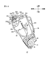
図23は、現像カートリッジ27の他の実施形態を示す斜視図である。この図23において、上述した各部に相当する部分には、それら各部と同一の参照符号が付されている。また、以下では、その同一の参照符号を付した各部についての詳細な説明を省略する。
Further, since the drum unit 26 can be attached to and detached from the main casing 2, maintenance work such as jam processing and parts replacement can be easily performed. In addition, since the developing cartridge 27 can be replaced individually, the cost for maintenance (maintenance cost) can be reduced.
6). Other Embodiments of Developing Cartridge FIG. 23 is a perspective view showing another embodiment of the developing cartridge 27. In FIG. 23, portions corresponding to the above-described portions are denoted by the same reference numerals as those portions. Further, in the following, detailed description of each part given the same reference numeral is omitted.

この実施形態に係る現像カートリッジ27では、取っ手214が備えられておらず、現像フレーム36の上壁202において、幅方向の両端部に、押圧部材の一例としての板ばね部材401が設けられている。
板ばね部材401は、付勢部の一例としての一端部402が、ねじ403によって、上壁202の上面に固定されている。そして、板ばね部材401は、一端部402から上方に屈曲し、さらに幅方向外方へと屈曲して、幅方向外方に向けて延びている。そして、板ばね部材401の他端部404は、現像フレーム36の側壁201よりも幅方向外方に突出し、離間押圧機構303の押圧作用部317からの押圧力が入力される突出部を形成している。
In the developing cartridge 27 according to this embodiment, the handle 214 is not provided, and a leaf spring member 401 as an example of a pressing member is provided at both ends in the width direction on the upper wall 202 of the developing frame 36. .
One end portion 402 of the leaf spring member 401 as an example of an urging portion is fixed to the upper surface of the upper wall 202 by a screw 403. The leaf spring member 401 is bent upward from the one end portion 402, further bent outward in the width direction, and extends outward in the width direction. The other end portion 404 of the leaf spring member 401 protrudes outward in the width direction from the side wall 201 of the developing frame 36 to form a protruding portion to which the pressing force from the pressing action portion 317 of the separation pressing mechanism 303 is input. ing.

このような構成においても、離間押圧機構303の押圧作用部317が、板ばね部材401の他端部404に上方から当接し、その他端部404を下方に向けて押圧すると、板ばね部材401が弾性変形し、その弾性変形による板ばね部材401の付勢力が現像フレーム36の上壁202に入力され、現像フレーム36が下方に向けて付勢されることにより、現像ローラ39が感光ドラム29に押圧される。そのため、図6に示す現像カートリッジ27と同様な効果を奏することができる。
7.現像カートリッジの他の実施形態
図24および図25は、現像カートリッジ27の他の実施形態を示す斜視図である。図24および図25において、上述した各部に相当する部分には、それら各部と同一の参照符号が付されている。また、以下では、その同一の参照符号を付した各部についての詳細な説明を省略する。
Even in such a configuration, when the pressing action portion 317 of the separation pressing mechanism 303 comes into contact with the other end portion 404 of the leaf spring member 401 from above and presses the other end portion 404 downward, the leaf spring member 401 is moved. The urging force of the leaf spring member 401 due to the elastic deformation is input to the upper wall 202 of the developing frame 36, and the developing frame 36 is urged downward, whereby the developing roller 39 is applied to the photosensitive drum 29. Pressed. Therefore, the same effect as the developing cartridge 27 shown in FIG. 6 can be obtained.
7). Other Embodiments of Developing Cartridge FIGS. 24 and 25 are perspective views showing other embodiments of the developing cartridge 27. In FIG. 24 and FIG. 25, the same reference numerals are assigned to the parts corresponding to the above-described parts. Further, in the following, detailed description of each part given the same reference numeral is omitted.

この実施形態に係る現像カートリッジ27では、ばねガイド部材216、当接部材217およびコイルばね218が備えられておらず、現像フレーム36の端面の一例としての上壁202の前端部に、その幅方向(現像ローラ39の軸方向)の全幅にわたって、スポンジまたはゴムなどの弾性材料からなる角柱状の弾性部材411が設けられている。
このような構成においても、離間押圧機構303の押圧作用部317が、現像カートリッジ27の押圧突起227に上方から当接して、各押圧突起227を下方に向けて押圧すると、取っ手214が傾倒状態から押圧状態に回動し、取っ手214によって弾性部材411が押圧されて、弾性部材411が収縮する。そして、その収縮による弾性部材411の付勢力が現像フレーム36の上壁202に入力され、現像フレーム36が下方に向けて付勢されることにより、現像ローラ39が感光ドラム29に押圧される。そのため、図6に示す現像カートリッジ27と同様な効果を奏することができる。
In the developing cartridge 27 according to this embodiment, the spring guide member 216, the contact member 217, and the coil spring 218 are not provided, and the width direction of the front end portion of the upper wall 202 as an example of the end surface of the developing frame 36 is not provided. A prismatic elastic member 411 made of an elastic material such as sponge or rubber is provided over the entire width (in the axial direction of the developing roller 39).
Even in such a configuration, when the pressing action portion 317 of the separation pressing mechanism 303 comes into contact with the pressing protrusion 227 of the developing cartridge 27 from above and presses each pressing protrusion 227 downward, the handle 214 is tilted. The elastic member 411 is pressed by the handle 214, and the elastic member 411 contracts. The urging force of the elastic member 411 due to the contraction is input to the upper wall 202 of the developing frame 36, and the developing frame 39 is urged downward, whereby the developing roller 39 is pressed against the photosensitive drum 29. Therefore, the same effect as the developing cartridge 27 shown in FIG. 6 can be obtained.

そのうえ、弾性部材411から上壁202の軸方向全幅に付勢力を与えることができ、その付勢力により現像ローラ39を感光ドラム29に向けて付勢することができる。そのため、現像ローラ39をその軸方向において感光ドラム29にバランスよく押圧させることができる。その結果、現像ローラ39から感光ドラム29にトナーを良好に供給することができる。
8.現像カートリッジの他の実施形態
図26および図27は、現像カートリッジ27の他の実施形態を示す斜視図である。また、図28は、図27に示す現像カートリッジ27の左側上端部の斜視図である。図26、図27および図28において、上述した各部に相当する部分には、それら各部と同一の参照符号が付されている。また、以下では、その同一の参照符号を付した各部についての詳細な説明を省略する。
In addition, an urging force can be applied from the elastic member 411 to the entire axial width of the upper wall 202, and the developing roller 39 can be urged toward the photosensitive drum 29 by the urging force. Therefore, the developing roller 39 can be pressed against the photosensitive drum 29 in a balanced manner in the axial direction. As a result, the toner can be satisfactorily supplied from the developing roller 39 to the photosensitive drum 29.
8). Other Embodiments of Developing Cartridge FIGS. 26 and 27 are perspective views showing other embodiments of the developing cartridge 27. FIG. 28 is a perspective view of the upper left portion of the developing cartridge 27 shown in FIG. In FIG. 26, FIG. 27 and FIG. 28, portions corresponding to the above-described portions are denoted by the same reference numerals as those portions. Further, in the following, detailed description of each part given the same reference numeral is omitted.

この実施形態に係る現像カートリッジ27では、取っ手214が備えられておらず、現像フレーム36の上壁202において、その前端部の幅方向の両端部に、それぞれ幅方向外方に向けて突出する押圧突起421が設けられている。この押圧突起421は、現像フレーム36に一体的に形成されている。そして、その押圧突起421の先端部には、スポンジまたはゴムなどの弾性材料からなる筒状の弾性リング422が装着されている。   In the developing cartridge 27 according to this embodiment, the handle 214 is not provided, and the upper wall 202 of the developing frame 36 is pressed toward both ends in the width direction of the front end portion thereof to protrude outward in the width direction. A protrusion 421 is provided. The pressing protrusion 421 is formed integrally with the developing frame 36. A cylindrical elastic ring 422 made of an elastic material such as sponge or rubber is attached to the tip of the pressing protrusion 421.

このような構成では、押圧突起421の弾性リング422が装着された部分が押圧突起受入部325(図16参照)に受け入れられる。そして、離間押圧機構303の押圧作用部317が、弾性リング422に上方から当接し、その弾性リング422を下方に向けて押圧すると、弾性リング422が弾性変形し、その弾性変形による弾性リング422の付勢力が押圧突起421に入力され、現像フレーム36が下方に向けて付勢されることにより、現像ローラ39が感光ドラム29に押圧される。そのため、図6に示す現像カートリッジ27と同様な効果を奏することができる。
9.現像カートリッジの他の実施形態
図29および図30は、現像カートリッジ27の他の実施形態を示す左前方から見た斜視図である。また、図31は、現像カートリッジ27の前方から見た正面図であり、図32は、図31に示す切断線B−Bにおける断面図である。図29ないし図32において、前述した各部に相当する部分には、それら各部と同一の参照符号が付されている。また、以下では、その同一の参照符号を付した各部についての詳細な説明を省略する。
In such a configuration, a portion where the elastic ring 422 of the pressing protrusion 421 is attached is received by the pressing protrusion receiving portion 325 (see FIG. 16). When the pressing action portion 317 of the separation pressing mechanism 303 comes into contact with the elastic ring 422 from above and presses the elastic ring 422 downward, the elastic ring 422 is elastically deformed, and the elastic ring 422 is caused by the elastic deformation. The urging force is input to the pressing protrusion 421 and the developing frame 36 is urged downward, whereby the developing roller 39 is pressed against the photosensitive drum 29. Therefore, the same effect as the developing cartridge 27 shown in FIG. 6 can be obtained.
9. Other Embodiments of Developing Cartridge FIGS. 29 and 30 are perspective views of another embodiment of the developing cartridge 27 as seen from the left front. FIG. 31 is a front view of the developing cartridge 27 as viewed from the front, and FIG. 32 is a cross-sectional view taken along a cutting line BB shown in FIG. 29 to 32, parts corresponding to the above-described parts are denoted by the same reference numerals as those parts. Further, in the following, detailed description of each part given the same reference numeral is omitted.

前述の現像カートリッジ27では、図9に示すように、現像フレーム36の上壁202に、2つのばねガイド部材216が設けられている。そして、取っ手214の下面には、各当接部材217と対応する位置に、それぞれ対応する当接部材217を受け入れ可能な凹部225が形成されている。
これに対し、この現像カートリッジ27では、図30に示すように、取っ手214の下面に形成されている各凹部225に、円筒状のばねガイド部材216が設けられている。そして、現像フレーム36の上壁202には、図29ないし図31に示すように、各当接部材217と対応する位置に、それぞれ対応する当接部材217の本体部219の先端部401を受け入れ可能な受入溝402が形成されている。
In the developing cartridge 27 described above, as shown in FIG. 9, two spring guide members 216 are provided on the upper wall 202 of the developing frame 36. A recess 225 that can receive the corresponding contact member 217 is formed on the lower surface of the handle 214 at a position corresponding to each contact member 217.
On the other hand, in this developing cartridge 27, as shown in FIG. 30, a cylindrical spring guide member 216 is provided in each recess 225 formed on the lower surface of the handle 214. As shown in FIGS. 29 to 31, the top end portion 401 of the main body 219 of the corresponding contact member 217 is received on the upper wall 202 of the developing frame 36 at a position corresponding to each contact member 217. A possible receiving groove 402 is formed.

より具体的には、各ばねガイド部材216は、取っ手214と一体的に形成されている。各ばねガイド部材216の先端部は、凹部225外に突出している。各ばねガイド部材216の周面には、その中心軸方向に延びる複数の溝部223が、それぞれ取っ手214側の端縁から中心軸方向の途中部まで形成されている。
当接部材217は、図32に示すように、各係止爪部222がばねガイド部材216の溝部223に係止し、本体部219がガイド部材216から突出した状態に設けられている。本体部219の先端部401は、側面視略半円形状をなし、前後方向に延びるリブ状に形成されている。
More specifically, each spring guide member 216 is formed integrally with the handle 214. The distal end portion of each spring guide member 216 protrudes out of the recess 225. On the peripheral surface of each spring guide member 216, a plurality of groove portions 223 extending in the central axis direction are formed from the edge on the handle 214 side to the middle portion in the central axis direction.
As shown in FIG. 32, the contact member 217 is provided in a state in which each locking claw portion 222 is locked to the groove portion 223 of the spring guide member 216 and the main body portion 219 protrudes from the guide member 216. The front end 401 of the main body 219 has a substantially semicircular shape when viewed from the side, and is formed in a rib shape extending in the front-rear direction.

また、コイルばね218は、取っ手214の下面と当接部材217との間で圧縮された状態に設けられて、当接部材217をばねガイド部材216から抜ける方向に付勢している。
取っ手214が傾倒状態に傾倒した状態では、各受入溝402に各当接部材217の先端部401が受け入れられて、各先端部401が各受入溝402の底面(現像フレーム36の上壁202)に当接する。そして、取っ手214が傾倒状態から押圧状態へ回動されると、各当接部材217が取っ手214側へ押されて、各コイルばね218が圧縮される。そして、その圧縮による各コイルばね218の付勢力が、各当接部材217から現像フレーム36の上壁202に入力され、現像フレーム36が下方に向けて付勢されることにより、現像ローラ39が感光ドラム29に押圧される。
The coil spring 218 is provided in a compressed state between the lower surface of the handle 214 and the abutting member 217, and urges the abutting member 217 in a direction to be removed from the spring guide member 216.
When the handle 214 is tilted to the tilted state, the leading end portions 401 of the contact members 217 are received in the receiving grooves 402, and the leading end portions 401 are the bottom surfaces of the receiving grooves 402 (the upper wall 202 of the developing frame 36). Abut. When the handle 214 is rotated from the tilted state to the pressed state, each contact member 217 is pressed toward the handle 214 and each coil spring 218 is compressed. Then, the urging force of each coil spring 218 due to the compression is input from each contact member 217 to the upper wall 202 of the developing frame 36, and the developing frame 36 is urged downward, whereby the developing roller 39 is moved. The photosensitive drum 29 is pressed.

このように、ばねガイド部材216、当接部材217およびコイルばね218が取っ手214に設けられてもよい。この構成を採用することにより、それらの部材を現像フレーム36に設ける必要をなくすことができ、現像フレーム36の構成の簡素化を図ることができる。   Thus, the spring guide member 216, the contact member 217, and the coil spring 218 may be provided on the handle 214. By adopting this configuration, it is possible to eliminate the necessity of providing these members on the development frame 36, and to simplify the configuration of the development frame 36.

1 カラーレーザプリンタ
2 本体ケーシング
26 ドラムユニット
27 現像カートリッジ
29 感光ドラム
36 現像フレーム
39 現像ローラ
201 側壁
202 上壁
214 取っ手
216 ばねガイド部材
218 コイルばね
225 凹部
227 押圧突起
310 直動カム部材
DESCRIPTION OF SYMBOLS 1 Color laser printer 2 Main body casing 26 Drum unit 27 Developing cartridge 29 Photosensitive drum 36 Developing frame 39 Developing roller 201 Side wall 202 Upper wall 214 Handle 216 Spring guide member 218 Coil spring 225 Concavity 227 Pressing protrusion 310 Direct acting cam member

Claims (9)

静電潜像が形成される像担持体に現像剤を供給して、当該静電潜像を可視像化するための現像剤担持体と、
現像剤を収容し、前記現像剤担持体が支持される現像剤担持体支持部を一方側端部に有する筐体と、
前記筐体における前記現像剤担持体支持部と反対側の他方側端部に、前記現像剤担持体の軸方向に延びる回動軸線を中心に回動自在に設けられ、前記筐体よりも前記現像剤担持体の軸方向における外方に突出し、外部から押圧力が入力される突出部、および、前記筐体の前記軸方向の側面よりも前記軸方向における内方に、前記軸方向に間隔を隔てて2つ設けられ、前記突出部に押圧力が入力されたときに、前記現像剤担持体が前記像担持体に押圧される方向に前記筐体を付勢する付勢部を有し、当該押圧力により回動して、前記付勢部を介して前記現像剤担持体が前記像担持体に押圧される方向に前記筐体を押圧する押圧部材とを備えていることを特徴とする、現像カートリッジ。
A developer carrier for supplying a developer to an image carrier on which an electrostatic latent image is formed to visualize the electrostatic latent image; and
A housing that contains a developer and has a developer carrier support portion on one side end on which the developer carrier is supported;
The other end of the housing opposite to the developer carrier support portion is provided to be rotatable about a rotation axis extending in the axial direction of the developer carrier, and more than the housing. A protruding portion that protrudes outward in the axial direction of the developer carrying member and receives a pressing force from the outside, and an interval in the axial direction that is inward in the axial direction from the side surface in the axial direction of the housing And a biasing portion that biases the housing in a direction in which the developer carrier is pressed against the image carrier when a pressing force is input to the protrusion. And a pressing member that is rotated by the pressing force and presses the housing in a direction in which the developer carrier is pressed against the image carrier via the biasing portion. A developing cartridge.
前記押圧部材は、前記現像カートリッジを移動させる際に把持される取っ手を兼ねていることを特徴とする、請求項1に記載の現像カートリッジ。   The developing cartridge according to claim 1, wherein the pressing member also serves as a handle that is gripped when the developing cartridge is moved. 前記押圧部材に設けられ、前記押圧力による前記付勢部の弾性変形をガイドするガイド部材を備えていることを特徴とする、請求項1または2に記載の現像カートリッジ。   The developing cartridge according to claim 1, further comprising a guide member that is provided on the pressing member and guides elastic deformation of the urging portion due to the pressing force. 前記付勢部は、1N以上20N以下の付勢力を発生させることを特徴とする、請求項1ないし3のいずれかに記載の現像カートリッジ。   The developing cartridge according to claim 1, wherein the urging unit generates an urging force of 1 N or more and 20 N or less. 前記現像カートリッジは、各色に対応して設けられる複数の前記像担持体を備えるカラー画像形成装置に用いられることを特徴とする、請求項1ないし4のいずれかに記載の現像カートリッジ。   5. The developing cartridge according to claim 1, wherein the developing cartridge is used in a color image forming apparatus including a plurality of the image carriers provided corresponding to the respective colors. 6. 前記現像カートリッジは、前記カラー画像形成装置において、前記筐体の前記一方側端部が相対的に下方に位置し、前記筐体の前記他方側端部が相対的に上方に位置するように配置されることを特徴とする、請求項5に記載の現像カートリッジ。   The developing cartridge is disposed in the color image forming apparatus such that the one end of the casing is positioned relatively downward and the other end of the casing is positioned relatively upward. The developing cartridge according to claim 5, wherein 前記カラー画像形成装置は、装置本体と、前記装置本体に対して着脱可能に装着され、複数の前記像担持体を一体的に保持する像担持体ユニットとを備えており、
前記現像カートリッジは、前記像担持体ユニットに対して着脱可能に装着され、
前記押圧部材は、前記現像カートリッジが前記像担持体ユニットに装着された状態で、前記像担持体ユニットの着脱方向と交差する方向に延びる回動軸線を中心に、当該着脱方向と交差する起立状態と前記像担持体ユニットの装着時の移動方向の上流側に傾倒する傾倒状態とに回動可能に設けられていることを特徴とする、請求項5または6に記載の現像カートリッジ。
The color image forming apparatus includes an apparatus main body and an image carrier unit that is detachably attached to the apparatus main body and integrally holds a plurality of the image carriers.
The developing cartridge is detachably attached to the image carrier unit,
The pressing member is in an upright state intersecting with the attaching / detaching direction about a rotation axis extending in a direction intersecting with the attaching / detaching direction of the image carrier unit in a state where the developing cartridge is mounted on the image carrier unit. 7. The developing cartridge according to claim 5, wherein the developing cartridge is rotatably provided in a tilted state in which the image carrier unit is tilted to an upstream side in a moving direction when the image carrier unit is mounted.
請求項1ないし7のいずれかに記載の現像カートリッジと、
前記押圧部材に押圧力を入力する押圧力入力部材とを備えていることを特徴とする、画像形成装置。
A developing cartridge according to any one of claims 1 to 7,
An image forming apparatus comprising: a pressing force input member that inputs a pressing force to the pressing member.
装置本体と、
前記装置本体に対して着脱可能に装着され、複数の像担持体を一体的に保持する像担持体ユニットとを備え、
前記現像カートリッジは、前記像担持体ユニットに対して着脱可能に装着されることを特徴とする、請求項8に記載の画像形成装置。
The device body;
An image carrier unit that is detachably attached to the apparatus main body and integrally holds a plurality of image carriers,
9. The image forming apparatus according to claim 8, wherein the developing cartridge is detachably attached to the image carrier unit.
JP2009255251A 2005-12-27 2009-11-06 Developing cartridge and image forming apparatus Active JP4475361B2 (en)

Priority Applications (1)

Application Number Priority Date Filing Date Title
JP2009255251A JP4475361B2 (en) 2005-12-27 2009-11-06 Developing cartridge and image forming apparatus

Applications Claiming Priority (2)

Application Number Priority Date Filing Date Title
JP2005376113 2005-12-27
JP2009255251A JP4475361B2 (en) 2005-12-27 2009-11-06 Developing cartridge and image forming apparatus

Related Parent Applications (1)

Application Number Title Priority Date Filing Date
JP2009111974A Division JP4475353B2 (en) 2005-12-27 2009-05-01 Developing cartridge and image forming apparatus

Publications (2)

Publication Number Publication Date
JP2010026541A true JP2010026541A (en) 2010-02-04
JP4475361B2 JP4475361B2 (en) 2010-06-09

Family

ID=38213935

Family Applications (3)

Application Number Title Priority Date Filing Date
JP2009111974A Active JP4475353B2 (en) 2005-12-27 2009-05-01 Developing cartridge and image forming apparatus
JP2009255251A Active JP4475361B2 (en) 2005-12-27 2009-11-06 Developing cartridge and image forming apparatus
JP2009255250A Active JP4582253B2 (en) 2005-12-27 2009-11-06 Developing cartridge and image forming apparatus

Family Applications Before (1)

Application Number Title Priority Date Filing Date
JP2009111974A Active JP4475353B2 (en) 2005-12-27 2009-05-01 Developing cartridge and image forming apparatus

Family Applications After (1)

Application Number Title Priority Date Filing Date
JP2009255250A Active JP4582253B2 (en) 2005-12-27 2009-11-06 Developing cartridge and image forming apparatus

Country Status (3)

Country Link
JP (3) JP4475353B2 (en)
CN (1) CN1991622B (en)
ES (1) ES2358979T3 (en)

Cited By (7)

* Cited by examiner, † Cited by third party
Publication number Priority date Publication date Assignee Title
CN102650840A (en) * 2011-02-28 2012-08-29 兄弟工业株式会社 Image forming apparatus and holder
EP2515183A2 (en) 2011-04-22 2012-10-24 Brother Kogyo Kabushiki Kaisha Image forming device having process unit with improved handgrips
JP2012212073A (en) * 2011-03-31 2012-11-01 Brother Ind Ltd Photoreceptor unit and image forming apparatus
JP2014071136A (en) * 2012-09-27 2014-04-21 Brother Ind Ltd Image forming apparatus
JP2015206882A (en) * 2014-04-18 2015-11-19 キヤノン株式会社 image forming system
US9268300B2 (en) 2012-02-22 2016-02-23 Ricoh Company, Ltd. Process unit including a rotatable shaft along a driving force vector and image forming apparatus including the same
KR20170094162A (en) 2014-11-28 2017-08-17 캐논 가부시끼가이샤 Cartridge, member configuring cartridge and image formation device

Families Citing this family (6)

* Cited by examiner, † Cited by third party
Publication number Priority date Publication date Assignee Title
CN102707604A (en) * 2009-11-21 2012-10-03 珠海赛纳打印科技股份有限公司 Developing case, image carrier case matched with developing case for use, and processing case comprising developing case and image carrier case
JP5630038B2 (en) * 2010-03-10 2014-11-26 セイコーエプソン株式会社 Unit attaching / detaching device and recording device
JP5760642B2 (en) * 2011-04-22 2015-08-12 ブラザー工業株式会社 Image forming apparatus
CN105607451B (en) * 2015-12-29 2022-11-08 珠海天威飞马打印耗材有限公司 Processing box
JP7047541B2 (en) * 2018-03-30 2022-04-05 ブラザー工業株式会社 Develop cartridge
WO2020196255A1 (en) * 2019-03-26 2020-10-01 Brother Kogyo Kabushiki Kaisha Drum cartridge and developing cartridge

Family Cites Families (7)

* Cited by examiner, † Cited by third party
Publication number Priority date Publication date Assignee Title
US5300979A (en) * 1990-10-17 1994-04-05 Sanyo Electric Co., Ltd. Clamshell type image forming apparatus
JPH07295461A (en) * 1994-04-26 1995-11-10 Nec Corp Ep cartridge for electrophotographic system
DE19734678B4 (en) * 1996-08-23 2017-03-02 Schaeffler Technologies AG & Co. KG Hydrodynamic torque converter
JP3648173B2 (en) * 2001-05-16 2005-05-18 シャープ株式会社 Image forming apparatus
JP4073748B2 (en) * 2002-09-27 2008-04-09 シャープ株式会社 Image forming apparatus
JP3797352B2 (en) * 2003-08-25 2006-07-19 村田機械株式会社 Image forming apparatus
JP4622243B2 (en) * 2003-12-19 2011-02-02 富士ゼロックス株式会社 Image forming apparatus

Cited By (25)

* Cited by examiner, † Cited by third party
Publication number Priority date Publication date Assignee Title
CN102650840A (en) * 2011-02-28 2012-08-29 兄弟工业株式会社 Image forming apparatus and holder
US8712283B2 (en) 2011-02-28 2014-04-29 Brother Kogyo Kabushiki Kaisha Image forming apparatus
JP2012212073A (en) * 2011-03-31 2012-11-01 Brother Ind Ltd Photoreceptor unit and image forming apparatus
EP2515183A2 (en) 2011-04-22 2012-10-24 Brother Kogyo Kabushiki Kaisha Image forming device having process unit with improved handgrips
EP2515183A3 (en) * 2011-04-22 2014-06-18 Brother Kogyo Kabushiki Kaisha Image forming device having process unit with improved handgrips
US8811856B2 (en) 2011-04-22 2014-08-19 Brother Kogyo Kabushiki Kaisha Image forming device having process unit with improved handgrips
US9268300B2 (en) 2012-02-22 2016-02-23 Ricoh Company, Ltd. Process unit including a rotatable shaft along a driving force vector and image forming apparatus including the same
JP2014071136A (en) * 2012-09-27 2014-04-21 Brother Ind Ltd Image forming apparatus
JP2015206882A (en) * 2014-04-18 2015-11-19 キヤノン株式会社 image forming system
US11131960B2 (en) 2014-11-28 2021-09-28 Canon Kabushiki Kaisha Cartridge, member constituting cartridge, and image forming apparatus
KR20220015514A (en) 2014-11-28 2022-02-08 캐논 가부시끼가이샤 Cartridge, member configuring cartridge and image formation device
KR20200097814A (en) 2014-11-28 2020-08-19 캐논 가부시끼가이샤 Cartridge, member configuring cartridge and image formation device
KR20170094162A (en) 2014-11-28 2017-08-17 캐논 가부시끼가이샤 Cartridge, member configuring cartridge and image formation device
EP3936943A1 (en) 2014-11-28 2022-01-12 Canon Kabushiki Kaisha Cartridge, member constituting cartridge, and image forming apparatus
EP3936944A1 (en) 2014-11-28 2022-01-12 Canon Kabushiki Kaisha Cartridge, member constituting cartridge, and image forming apparatus
DE112015005353B4 (en) 2014-11-28 2022-02-03 Canon Kabushiki Kaisha CARTRIDGE
US10386786B2 (en) 2014-11-28 2019-08-20 Canon Kabushiki Kaisha Cartridge, member constituting cartridge, and image forming apparatus
EP3951509A1 (en) 2014-11-28 2022-02-09 Canon Kabushiki Kaisha Cartridge, member constituting cartridge, and image forming apparatus
US11307529B2 (en) 2014-11-28 2022-04-19 Canon Kabushiki Kaisha Cartridge, member constituting cartridge, and image forming apparatus
US11314199B2 (en) 2014-11-28 2022-04-26 Canon Kabushiki Kaisha Cartridge, member constituting cartridge, and image forming apparatus
KR20220146719A (en) 2014-11-28 2022-11-01 캐논 가부시끼가이샤 Cartridge
EP3761121B1 (en) * 2014-11-28 2023-01-11 Canon Kabushiki Kaisha Cartridge, member constituting cartridge, and image forming apparatus
US11693355B2 (en) 2014-11-28 2023-07-04 Canon Kabushiki Kaisha Cartridge, member constituting cartridge, and image forming apparatus
US11698601B2 (en) 2014-11-28 2023-07-11 Canon Kabushiki Kaisha Cartridge, member constituting cartridge, and image forming apparatus
KR20230151078A (en) 2014-11-28 2023-10-31 캐논 가부시끼가이샤 Cartridge

Also Published As

Publication number Publication date
JP4582253B2 (en) 2010-11-17
ES2358979T3 (en) 2011-05-17
JP2009169441A (en) 2009-07-30
JP4475361B2 (en) 2010-06-09
CN1991622B (en) 2010-05-19
JP4475353B2 (en) 2010-06-09
CN1991622A (en) 2007-07-04
JP2010026540A (en) 2010-02-04

Similar Documents

Publication Publication Date Title
JP4332807B2 (en) Developing cartridge and image forming apparatus
JP4332806B2 (en) Developing unit and image forming apparatus
JP4475361B2 (en) Developing cartridge and image forming apparatus
JP4586726B2 (en) Image forming apparatus
JP4581948B2 (en) Image forming apparatus
JP4345018B2 (en) Image forming apparatus and tandem process unit
JP4389174B2 (en) Image forming apparatus
JP4661507B2 (en) Image forming apparatus
JP4622830B2 (en) Developing cartridge, process unit, and image forming apparatus
JP4329041B2 (en) Tandem type photoreceptor unit and image forming apparatus
JP4240326B2 (en) Image forming apparatus and developing cartridge
JP4882517B2 (en) Process unit and image forming apparatus
US7561827B2 (en) Developing cartridge having a handle that contacts an exposure unit when installed in an image forming apparatus
US7706720B2 (en) Restricting unit for restricting a supporter of a plurality of developers in an image forming apparatus
JP4687535B2 (en) Image forming apparatus
JP2007148286A (en) Developing cartridge, image carrier holding unit, process unit and image forming apparatus
JP4423573B2 (en) Image forming apparatus and developing cartridge

Legal Events

Date Code Title Description
A621 Written request for application examination

Free format text: JAPANESE INTERMEDIATE CODE: A621

Effective date: 20091113

TRDD Decision of grant or rejection written
A01 Written decision to grant a patent or to grant a registration (utility model)

Free format text: JAPANESE INTERMEDIATE CODE: A01

Effective date: 20100216

A01 Written decision to grant a patent or to grant a registration (utility model)

Free format text: JAPANESE INTERMEDIATE CODE: A01

A61 First payment of annual fees (during grant procedure)

Free format text: JAPANESE INTERMEDIATE CODE: A61

Effective date: 20100301

R150 Certificate of patent or registration of utility model

Free format text: JAPANESE INTERMEDIATE CODE: R150

Ref document number: 4475361

Country of ref document: JP

Free format text: JAPANESE INTERMEDIATE CODE: R150

FPAY Renewal fee payment (event date is renewal date of database)

Free format text: PAYMENT UNTIL: 20130319

Year of fee payment: 3

FPAY Renewal fee payment (event date is renewal date of database)

Free format text: PAYMENT UNTIL: 20130319

Year of fee payment: 3

FPAY Renewal fee payment (event date is renewal date of database)

Free format text: PAYMENT UNTIL: 20140319

Year of fee payment: 4