JP2010026247A - Imaging optical system and electronic imaging apparatus having the same - Google Patents
Imaging optical system and electronic imaging apparatus having the same Download PDFInfo
- Publication number
- JP2010026247A JP2010026247A JP2008187617A JP2008187617A JP2010026247A JP 2010026247 A JP2010026247 A JP 2010026247A JP 2008187617 A JP2008187617 A JP 2008187617A JP 2008187617 A JP2008187617 A JP 2008187617A JP 2010026247 A JP2010026247 A JP 2010026247A
- Authority
- JP
- Japan
- Prior art keywords
- lens
- lens group
- optical system
- positive
- refractive power
- Prior art date
- Legal status (The legal status is an assumption and is not a legal conclusion. Google has not performed a legal analysis and makes no representation as to the accuracy of the status listed.)
- Granted
Links
Images


Classifications
-
- G—PHYSICS
- G02—OPTICS
- G02B—OPTICAL ELEMENTS, SYSTEMS OR APPARATUS
- G02B15/00—Optical objectives with means for varying the magnification
- G02B15/14—Optical objectives with means for varying the magnification by axial movement of one or more lenses or groups of lenses relative to the image plane for continuously varying the equivalent focal length of the objective
- G02B15/144—Optical objectives with means for varying the magnification by axial movement of one or more lenses or groups of lenses relative to the image plane for continuously varying the equivalent focal length of the objective having four groups only
- G02B15/1441—Optical objectives with means for varying the magnification by axial movement of one or more lenses or groups of lenses relative to the image plane for continuously varying the equivalent focal length of the objective having four groups only the first group being positive
- G02B15/144113—Optical objectives with means for varying the magnification by axial movement of one or more lenses or groups of lenses relative to the image plane for continuously varying the equivalent focal length of the objective having four groups only the first group being positive arranged +-++
Landscapes
- Physics & Mathematics (AREA)
- General Physics & Mathematics (AREA)
- Optics & Photonics (AREA)
- Lenses (AREA)
Abstract
Description
本発明は、特に電子撮像光学系に適した薄型でありながら高変倍比でかつ結像性能に優れた結像光学系(ズーム光学系)及び該結像光学系を有する電子撮像装置に関するものである。
BACKGROUND OF THE
デジタルカメラは高画素数化(高画質化)や小型薄型化において実用レベルを達成し、機能的にも市場的にも銀塩35mmフィルムカメラにとって代わってしまった。そこで、次なる進化の方向の1つとして、そのままの小ささ薄さで高変倍比とともにさらなる高画素数化が強く求められている。 Digital cameras have achieved practical levels in terms of increasing the number of pixels (higher image quality) and reducing the size and thickness, and have been replaced by silver salt 35 mm film cameras, both functionally and commercially. Therefore, as one of the next evolution directions, there is a strong demand for further increase in the number of pixels as well as the high zoom ratio with the small size and thinness.
これまで、高変倍に強いとして用いられてきたズーム光学系として、たとえば、特許文献1に開示された光学系がある。特許文献1では、物体側から順に、正の屈折力を有する第1レンズ群、負の屈折力を有する第2レンズ群、正の屈折力を有する第3レンズ群、負の屈折力を有する第4レンズ群、正の屈折力を有する第5レンズ群からなる、いわゆる正先行型ズーム光学系が開示されている。
For example, there is an optical system disclosed in
この光学系は、ズーム比が5乃至10、広角端におけるF値は2.4でありながら高い結像性能を有している。しかしながら、各レンズ群の光軸方向の厚みが大きい。そのため、沈胴式鏡筒を採用してもカメラ筐体を薄くすることは困難である。なお、沈胴式鏡筒とは、レンズ鏡筒ユニットをカメラ筐体の厚み(奥行き)方向に収納する方式の鏡筒のことである。 This optical system has a high imaging performance while the zoom ratio is 5 to 10 and the F-number at the wide angle end is 2.4. However, the thickness of each lens group in the optical axis direction is large. Therefore, it is difficult to make the camera housing thin even if a retractable lens barrel is employed. The retractable lens barrel is a lens barrel of a type in which the lens barrel unit is accommodated in the thickness (depth) direction of the camera casing.
また、特許文献2には、色収差を良好に補正しながらレンズ要素を薄くし、レンズ構成枚数を削減して薄型化を図った光学系が開示されている。このような光学系を実現するため、特許文献2では、従来のガラスにはない有効な分散特性あるいは部分分散特性を有する透明媒質を用いている。しかしながら、前記透明媒質を用いたレンズの形状や配置が必ずしも適切ではないため、十分に薄型化出来ているとは言い難い。
Further,
本発明は、上記従来の課題に鑑みてなされたものであり、薄型であることと高変倍比であることを両立させつつも、高変倍比化において特に厳しく求められる色収差を良好に行える結像光学系及びそれを有する電子撮像装置を提供することを目的とする。 The present invention has been made in view of the above-described conventional problems, and can satisfactorily achieve chromatic aberration that is particularly strictly demanded in the case of a high zoom ratio while achieving both a low thickness and a high zoom ratio. An object of the present invention is to provide an imaging optical system and an electronic imaging apparatus having the same.
上記の課題を解決するため、本発明の結像光学系は、最も物体側のレンズ群Iと、開口絞りと、前記レンズ群Iと前記開口絞りの間に配置され全体として負の屈折力を有するレンズ群Aを有し、前記レンズ群Aは、正レンズLAと負レンズLBが接合された接合レンズ成分を含み、前記レンズ群Iと前記レンズ群Aとの光軸上の距離がズーミングを目的として変動する結像光学系であり、前記接合レンズ成分は非球面からなる接合面を有し、光軸方向をz、光軸に垂直な方向をhとする座標軸とし、Rを球面成分の光軸上における曲率半径、kを円錐定数、A4,A6,A8,A10・・・を非球面係数として、非球面の形状を下記の式(1)で表すと共に、
z=h2/R[1+{1−(1+k)h2/R2 }1/2 ]
+A4 h4 +A6 h6 +A8 h8 +A10h10+・・・ …(1)
偏倚量を下記の式(2)で表した場合、
Δz=z−h2/R[1+{1−h2/R2 }1/2 ] …(2)
以下の条件式(3a)または条件式(3b)を満足することを特徴としている。
RC≧0のとき
ΔzC (h)≦(ΔzA(h)+ΔzB(h))/2〈但し、h=2.5a〉 …(3a)
RC≦0のとき
ΔzC (h)≧(ΔzA(h)+ΔzB(h))/2〈但し、h=2.5a〉 …(3b)
ここで、
zAは前記正レンズLAの空気接触面の形状であって、式(1)に従う形状、
zBは前記負レンズLBの空気接触面の形状であって、式(1)に従う形状、
zCは前記接合面の形状であって、式(1)に従う形状、
ΔzAは前記正レンズLAの空気接触面における偏倚量であって、式(2)に従う量、
ΔzBは前記負レンズLBの空気接触面における偏倚量であって、式(2)に従う量、
ΔzCは前記接合面における偏倚量であって、式(2)に従う量、
RCは前記接合面の近軸曲率半径、
aは以下の条件式(4)に従う量、
a=(y10)2・log10γ/fw ・・・(4)
また、式(4)において、
y10は最大像高、
fwは前記結像光学系の広角端における全系の焦点距離
γは前記結像光学系におけるズーム比(望遠端での全系焦点距離/広角端での全系焦点距離)、
また、各面の面頂を原点とするため、常にz(0)=0である。
In order to solve the above problems, the imaging optical system of the present invention is disposed between the lens group I closest to the object side, the aperture stop, and the lens group I and the aperture stop, and has a negative refractive power as a whole. The lens group A includes a cemented lens component in which a positive lens LA and a negative lens LB are cemented, and the distance on the optical axis between the lens group I and the lens group A zooms. An imaging optical system that varies as a purpose, wherein the cemented lens component has a cemented surface composed of an aspherical surface, the optical axis direction is z, the coordinate axis is h that is perpendicular to the optical axis, and R is a spherical component. The radius of curvature on the optical axis, k is a conic constant, A 4 , A 6 , A 8 , A 10 ... Are aspheric coefficients, and the shape of the aspheric surface is expressed by the following equation (1).
z = h 2 / R [1+ {1− (1 + k) h 2 / R 2 } 1/2 ]
+ A 4 h 4 + A 6 h 6 + A 8 h 8 + A 10 h 10 +... (1)
When the amount of bias is expressed by the following formula (2),
Δz = z−h 2 / R [1+ {1−h 2 / R 2 } 1/2 ] (2)
The following conditional expression (3a) or conditional expression (3b) is satisfied.
When R C ≧ 0 Δz C (h) ≦ (Δz A (h) + Δz B (h)) / 2 <where h = 2.5a> (3a)
When R C ≦ 0 Δz C (h) ≧ (Δz A (h) + Δz B (h)) / 2 (where h = 2.5a) (3b)
here,
z A is the shape of the air contact surface of the positive lens LA, and the shape according to equation (1),
z B is the shape of the air contact surface of the negative lens LB, and the shape according to equation (1),
z C is the shape of the joint surface, the shape according to the formula (1),
Δz A is a deviation amount on the air contact surface of the positive lens LA, and is an amount according to the equation (2),
Δz B is a deviation amount on the air contact surface of the negative lens LB, and is an amount according to the equation (2),
Δz C is a deviation amount in the joint surface, and is an amount according to the equation (2),
R C is the paraxial radius of curvature of the joint surface,
a is an amount according to the following conditional expression (4),
a = (y 10 ) 2 · log 10 γ / fw (4)
Moreover, in Formula (4),
y 10 is the maximum image height,
fw is the focal length of the entire system at the wide-angle end of the imaging optical system γ is the zoom ratio in the imaging optical system (total focal length at the telephoto end / total focal length at the wide-angle end),
Since the top of each surface is the origin, z (0) = 0 is always set.
また、本発明の電子撮像装置は、上記の結像光学系と、電子撮像素子と、前記結像光学系を通じて結像された像を前記電子撮像素子で撮像することによって得られた画像データを加工して前記像の形状を変化させた画像データとして出力する画像処理手段を有し、前記結像光学系がズームレンズであり、該ズームレンズが、無限遠物点合焦時に以下の条件式(17)を満足することを特徴とする電子撮像装置。
0.70<y07/(fw・tanω07w)<0.97 …(17)
但し、y07は前記電子撮像素子の有効撮像面内(撮像可能な面内)で中心から最も遠い点までの距離(最大像高)をy10としたときy07=0.7y10で表され、ω07wは広角端における前記撮像面上の中心からy07の位置に結ぶ像点に対応する物点方向の光軸に対する角度、fwは広角端における前記結像光学系の全系の焦点距離である。
Further, an electronic imaging device of the present invention provides image data obtained by capturing an image formed through the imaging optical system, the electronic imaging device, and the imaging optical system with the electronic imaging device. Image processing means for processing and outputting as image data in which the shape of the image is changed, the imaging optical system is a zoom lens, and when the zoom lens is focused on an object point at infinity, the following conditional expression An electronic imaging apparatus characterized by satisfying (17).
0.70 <y 07 / (fw · tan ω 07w ) <0.97 (17)
However, y 07 is represented by y 07 = 0.7y 10 when y 10 is the distance (maximum image height) from the center to the farthest point in the effective imaging plane (in the plane where imaging is possible) of the electronic imaging device. Ω 07w is an angle with respect to the optical axis in the object direction corresponding to the image point connecting from the center on the imaging surface at the wide-angle end to y 07 , and fw is the focal point of the entire system of the imaging optical system at the wide-angle end Distance.
本発明によれば、薄型であることと高変倍比であることを両立させつつも、高変倍比化において特に厳しく求められる色収差を良好に行える結像光学系及びそれを有する電子撮像装置を実現できる。 According to the present invention, an imaging optical system capable of satisfactorily obtaining chromatic aberration that is particularly strictly demanded in the case of a high zoom ratio, and an electronic imaging apparatus having the same, while achieving both a low thickness and a high zoom ratio Can be realized.
実施例の説明に先立ち、本実施形態の結像光学系の作用効果について説明する。
光学系を薄型化するためには、光学全長の短縮が必要である。この光学全長の短縮と高変倍率化を両立しようとした場合、色の球面収差や倍率色収差の像高に関する高次成分が大きくなりやすくなる。従来の光学系では、これらの収差の補正が困難であった。ここで、色の球面収差があると、球面収差が基準波長で良く補正されていても、他の波長において補正不足あるいは補正過剰な状態になっている。
Prior to the description of the examples, the effects of the imaging optical system of the present embodiment will be described.
In order to reduce the thickness of the optical system, it is necessary to shorten the total optical length. When trying to achieve both shortening of the optical total length and high magnification, high-order components related to color spherical aberration and image height of chromatic aberration of magnification tend to increase. In conventional optical systems, it is difficult to correct these aberrations. Here, if there is a spherical aberration of color, even if the spherical aberration is well corrected at the reference wavelength, the correction is insufficient or overcorrected at other wavelengths.
そこで、本実施形態の結像光学系は、最も物体側のレンズ群Iと、開口絞りと、レンズ群Iと開口絞りの間に配置され全体として負の屈折力を有するレンズ群Aを有し、レンズ群Aは、正レンズLAと負レンズLBが接合された接合レンズ成分を含み、レンズ群Iとレンズ群Aとの光軸上の距離がズーミングのために変動する結像光学系であり、接合レンズ成分は非球面からなる接合面を有する。なお、正レンズとは近軸焦点距離が正の値のレンズ、負レンズとは近軸焦点距離が負の値のレンズをさす。 Therefore, the imaging optical system of the present embodiment has the lens group I closest to the object side, the aperture stop, and the lens group A that is disposed between the lens group I and the aperture stop and has a negative refractive power as a whole. The lens group A is an imaging optical system that includes a cemented lens component in which a positive lens LA and a negative lens LB are cemented, and the distance on the optical axis between the lens group I and the lens group A varies due to zooming. The cemented lens component has a cemented surface composed of an aspheric surface. The positive lens is a lens having a positive paraxial focal length, and the negative lens is a lens having a negative paraxial focal length.
本実施形態の結像光学系では、接合レンズ成分の接合面を非球面とすることで、色の球面収差や倍率色収差を良好に補正することを可能にしている。特に、広角端においては、光学系を通過する光線高がレンズ群Aで最も高くなる。そこで、接合レンズ成分をレンズ群Aに導入すると、広角端において、その倍率色収差の像高に関する高次成分が容易に補正出来る。 In the imaging optical system of the present embodiment, the cemented lens component cemented surface is aspherical, so that it is possible to satisfactorily correct chromatic spherical aberration and lateral chromatic aberration. In particular, at the wide-angle end, the height of light passing through the optical system is highest in the lens group A. Therefore, when a cemented lens component is introduced into the lens group A, a higher-order component related to the image height of the lateral chromatic aberration can be easily corrected at the wide-angle end.
ただし、接合面を単純な非球面にするだけでは、色の球面収差や倍率色収差を十分に補正することは難しい。つまり、色の球面収差や倍率色収差を十分に補正するには、その非球面の形状が重要である。広角端における倍率色収差の像高に関する高次成分については、この高次成分が発生している場合、短波長(たとえばg線)に着目すると、正の中間像高にて基準波長(たとえばd線)に対して負側の値、正の最大像高にて正側の値をとるような状態になる。そこでこの高次成分を補正するためには、色消し作用のある接合面において、より像高の高い主光線に対する位置での面の曲率を、色消し力を弱める方向の曲率にすればよい。 However, it is difficult to sufficiently correct chromatic spherical aberration and lateral chromatic aberration only by making the cemented surface a simple aspherical surface. That is, the shape of the aspheric surface is important for sufficiently correcting the spherical aberration of color and the chromatic aberration of magnification. Regarding the high-order component related to the image height of the lateral chromatic aberration at the wide-angle end, when this high-order component is generated, focusing on the short wavelength (for example, g line), the reference wavelength (for example, the d line) at the positive intermediate image height. ), A negative value, and a positive value at the maximum positive image height. Therefore, in order to correct this higher-order component, the curvature of the surface at the position with respect to the principal ray having a higher image height may be set to a curvature in a direction in which the achromatic force is weakened on the achromatic surface.
すなわち、具体的には、光軸方向をz、光軸に垂直な方向をhとする座標軸とし、Rを球面成分の光軸上における曲率半径、kを円錐定数、A4,A6,A8,A10・・・を非球面係数として、非球面の形状を下記の式(1)で表すと共に、
z=h2/R[1+{1−(1+k)h2/R2 }1/2 ]
+A4 h4 +A6 h6 +A8 h8 +A10h10+・・・ …(1)
偏倚量を下記の式(2)で表した場合、
Δz=z−h2/R[1+{1−h2/R2 }1/2 ] …(2)
下記の条件式(3a)もしくは条件式(3b)を満足することが好ましい。
RC≧0のとき
ΔzC (h)≦(ΔzA(h)+ΔzB(h))/2〈但し、h=2.5a〉…(3a)
RC≦0のとき
ΔzC (h)≧(ΔzA(h)+ΔzB(h))/2〈但し、h=2.5a〉…(3b)
ここで、
zAは正レンズLAの空気接触面の形状であって、式(1)に従う形状、
zBは負レンズLBの空気接触面の形状であって、式(1)に従う形状、
zCは接合面の形状であって、式(1)に従う形状、
ΔzAは正レンズLAの空気接触面における偏倚量であって、式(2)に従う量、
ΔzBは負レンズLBの空気接触面における偏倚量であって、式(2)に従う量、
ΔzCは接合面における偏倚量であって、式(2)に従う量、
RCは接合面の近軸曲率半径、
aは以下の条件式(4)に従う量、
a=(y10)2・log10γ/fw …(4)
また、式(4)において、
y10は最大像高、
fwは結像光学系の広角端における全系の焦点距離、
γは結像光学系におけるズーム比(望遠端での全系焦点距離/広角端での全系焦点距離)、
また、各面の面頂を原点とするため、常にz(0)=0である。
Specifically, the coordinate axis is z, the optical axis direction is h, and the direction perpendicular to the optical axis is h, R is the radius of curvature of the spherical component on the optical axis, k is the conic constant, A 4 , A 6 , A 8 , A 10 ... As an aspheric coefficient, and the shape of the aspheric surface is expressed by the following formula (1).
z = h 2 / R [1+ {1− (1 + k) h 2 / R 2 } 1/2 ]
+ A 4 h 4 + A 6 h 6 + A 8 h 8 + A 10 h 10 +... (1)
When the amount of bias is expressed by the following formula (2),
Δz = z−h 2 / R [1+ {1−h 2 / R 2 } 1/2 ] (2)
It is preferable that the following conditional expression (3a) or conditional expression (3b) is satisfied.
When R C ≧ 0
Δz C (h) ≦ (Δz A (h) + Δz B (h)) / 2 <where h = 2.5a> (3a)
When R C ≦ 0
Δz C (h) ≧ (Δz A (h) + Δz B (h)) / 2 <where h = 2.5a> (3b)
here,
z A is the shape of the air contact surface of the positive lens LA, and the shape according to equation (1),
z B is the shape of the air contact surface of the negative lens LB, and the shape according to equation (1),
z C is the shape of the joint surface, the shape according to equation (1),
Δz A is a deviation amount on the air contact surface of the positive lens LA, and is an amount according to the equation (2),
Δz B is a deviation amount on the air contact surface of the negative lens LB, and is an amount according to the equation (2),
Δz C is the amount of deviation in the joint surface, and the amount according to equation (2),
R C is the paraxial radius of curvature of the joint surface,
a is an amount according to the following conditional expression (4),
a = (y 10 ) 2 · log 10 γ / fw (4)
Moreover, in Formula (4),
y 10 is the maximum image height,
fw is the focal length of the entire system at the wide angle end of the imaging optical system,
γ is the zoom ratio in the imaging optical system (total focal length at the telephoto end / total focal length at the wide angle end),
Since the top of each surface is the origin, z (0) = 0 is always set.
これら条件を外れると、接合面に非球面を導入してもその効果を発揮することが出来ない。逆に、以上の構成や条件を満足すれば、小型化薄型化に伴って著しく発生する色収差の補正ができるので、結像性能は維持向上できる。なお、以下に述べる材料の分散特性に関する条件を満たすと、さらに効果的に色収差が補正できる。 If these conditions are not met, even if an aspheric surface is introduced into the joint surface, the effect cannot be exhibited. On the contrary, if the above configuration and conditions are satisfied, the chromatic aberration that occurs remarkably with the reduction in size and thickness can be corrected, so that the imaging performance can be maintained and improved. Note that chromatic aberration can be more effectively corrected if the following conditions regarding the dispersion characteristics of the material are satisfied.
本実施形態の結像光学系は、横軸をνd、及び縦軸をθgFとする直交座標系において、
θgF=α×νd+β(但し、α=−0.00163)
で表される直線を設定したときに、以下の条件式(5)の範囲の下限値であるときの直線、及び上限値であるときの直線で定まる領域と、以下の条件式(6)で定まる領域との両方の領域に、正レンズLAのθgF及びνdが含まれることを特徴とする。
0.6700<β<0.9000 …(5)
3<νd<27 …(6)
ここで、
θgFは正レンズLAの部分分散比(ng−nF)/(nF−nC)、
νdは正レンズLAのアッベ数(nd−1)/(nF−nC)、
nd、nC、nF、ngは各々、正レンズLAのd線、C線、F線、g線の屈折率を表す。
The imaging optical system of the present embodiment is an orthogonal coordinate system in which the horizontal axis is νd and the vertical axis is θgF.
θgF = α × νd + β (where α = −0.00163)
When the straight line represented by is set, the area defined by the straight line when the range is the lower limit of the range of the following conditional expression (5) and the straight line when the upper limit is set, and the following conditional expression (6) It is characterized in that θgF and νd of the positive lens LA are included in both the fixed region and the fixed region.
0.6700 <β <0.9000 (5)
3 <νd <27 (6)
here,
θgF is the partial dispersion ratio (ng−nF) / (nF−nC) of the positive lens LA,
νd is the Abbe number (nd-1) / (nF-nC) of the positive lens LA,
nd, nC, nF, and ng represent the refractive indexes of the d-line, C-line, F-line, and g-line of the positive lens LA, respectively.
条件式(5)の下限値を下回ると、二次スペクトルによる軸上色収差、つまりF線とC線で色消しをしたときのg線の軸上色収差補正が十分でなくなる。そのため、撮像で得た画像において、像の鮮鋭さを確保しづらい。条件式(5)の上限値を上回ると、二次スペクトルによる軸上色収差が補正過剰となる。その結果、上限値を下回った場合と同様に、撮像した画像において、像の鮮鋭さを確保しづらい。 If the lower limit value of conditional expression (5) is not reached, axial chromatic aberration due to the secondary spectrum, that is, correction of axial chromatic aberration of the g line when the achromaticity is applied to the F line and the C line will be insufficient. Therefore, it is difficult to ensure the sharpness of the image in the image obtained by imaging. If the upper limit of conditional expression (5) is exceeded, axial chromatic aberration due to the secondary spectrum will be overcorrected. As a result, it is difficult to ensure the sharpness of the image in the captured image, as in the case where the value is below the upper limit.
条件式(6)の下限値・上限値いずれの側に超えても、F線とC線との色消し自体が困難で、ズーム時の色収差変動が大きくなる。このため、撮像した画像において、像の鮮鋭さを確保しづらい。 Even if either of the lower limit value and the upper limit value of conditional expression (6) is exceeded, it is difficult to erase the F-line and C-line itself, and the chromatic aberration fluctuation during zooming becomes large. For this reason, it is difficult to ensure the sharpness of the image in the captured image.
なお、条件式(5)に代えて、次の条件式(5’)を満足すると、より好ましい。
0.6850<β<0.8700 …(5’)
さらに、条件式(5)に代えて、次の条件式(5”)を満足すると、より好ましい。
0.7000<β<0.8500 …(5”)
It is more preferable that the following conditional expression (5 ′) is satisfied instead of conditional expression (5).
0.6850 <β <0.8700 (5 ′)
Furthermore, it is more preferable that the following conditional expression (5 ″) is satisfied instead of conditional expression (5).
0.7000 <β <0.8500 (5 ")
また、本実施形態の結像光学系は、上記の直交座標とは別に、横軸をνd、及び縦軸をθhgとする直交座標系において、
θhg=αhg×νd+βhg(但し、αhg=−0.00225)
で表される直線を設定したときに、以下の条件式(7)の範囲の下限値であるときの直線、及び上限値であるときの直線で定まる領域と、以下の条件式(6)で定まる領域との両方の領域に、正レンズLAのθhg及びνdが含まれることを特徴とする。
0.6350<βhg<0.9500 …(7)
3<νd<27 …(6)
ここで、
θhgは正レンズLAの部分分散比(nh−ng)/(nF−nC)、
nhは正レンズLAのh線の屈折率を表す。
In addition, the imaging optical system of the present embodiment is an orthogonal coordinate system in which the horizontal axis is νd and the vertical axis is θhg separately from the above-described orthogonal coordinates.
θhg = αhg × νd + βhg (where αhg = −0.00225)
When the straight line represented by is set, the region defined by the straight line when the range is the lower limit of the range of the following conditional expression (7) and the straight line when the upper limit is set, and the following conditional expression (6) It is characterized in that θhg and νd of the positive lens LA are included in both the fixed region and the fixed region.
0.6350 <βhg <0.9500 (7)
3 <νd <27 (6)
here,
θhg is the partial dispersion ratio (nh−ng) / (nF−nC) of the positive lens LA,
nh represents the refractive index of h-line of the positive lens LA.
条件式(7)の下限値を下回ると、二次スペクトルによる軸上色収差、つまりF線とC線で色消しをした場合のh線の軸上色収差補正が十分でなくなる。そのため、撮像した画像において紫の色フレア、色にじみが発生しやすい。条件式(7)の上限値を上回ると、凹レンズに用いたときの二次スペクトルによる軸上色収差、つまりF線とC線で色消しをした場合のh線の軸上色収差補正が十分でなくなる。そのため、撮像した画像において、紫の色フレア、色にじみが発生しやすい。 If the lower limit value of conditional expression (7) is not reached, axial chromatic aberration due to the secondary spectrum, that is, correction of axial chromatic aberration of the h-line when achromaticity is applied to the F-line and C-line will not be sufficient. Therefore, purple color flare and color blur are likely to occur in the captured image. If the upper limit of conditional expression (7) is exceeded, axial chromatic aberration due to the secondary spectrum when used for a concave lens, that is, axial chromatic aberration correction for h line when achromatic is applied to the F line and C line will not be sufficient. . Therefore, purple color flare and color blur are likely to occur in the captured image.
なお、条件式(7)に代えて、次の条件式(7’)を満足すると、より好ましい。
0.6700<βhg<0.9200 …(7’)
さらに、条件式(7)に代えて、次の条件式(7”)を満足すると、より好ましい。
0.7000<βhg<0.9000 …(7”)
It is more preferable that the following conditional expression (7 ′) is satisfied instead of conditional expression (7).
0.6700 <βhg <0.9200 (7 ′)
Furthermore, it is more preferable that the following conditional expression (7 ″) is satisfied instead of conditional expression (7).
0.7000 <βhg <0.9000 (7 ″)
また、本実施形態の結像光学系は、以下の条件式(8)を満足することが好ましい。
0.07≦θgF(LA)−θgF(LB)≦0.50 …(8)
ここで、
θgF(LA)は正レンズLAの部分分散比(ng−nF)/(nF−nC)、
θgF(LB)は負レンズLBの部分分散比(ng−nF)/(nF−nC)である。
Moreover, it is preferable that the imaging optical system of this embodiment satisfies the following conditional expression (8).
0.07 ≦ θgF (LA) −θgF (LB) ≦ 0.50 (8)
here,
θgF (LA) is the partial dispersion ratio (ng−nF) / (nF−nC) of the positive lens LA,
θgF (LB) is a partial dispersion ratio (ng−nF) / (nF−nC) of the negative lens LB.
この場合、正レンズ(正レンズLA)と負レンズ(負レンズLB)の組み合わせとなるので、色収差の補正が良好に行える。特に、この組み合わせで上記条件を満足すると、二次スペクトルによる軸上色収差の補正効果は大きく、画像の鮮鋭性が増す。 In this case, since a positive lens (positive lens LA) and a negative lens (negative lens LB) are combined, chromatic aberration can be corrected satisfactorily. In particular, when the above condition is satisfied with this combination, the effect of correcting the longitudinal chromatic aberration by the secondary spectrum is large, and the sharpness of the image is increased.
また、上記の条件式(8)に代えて、条件式(8’)を満足するのがより望ましい。
0.10≦θgF(LA)−θgF(LB)≦0.40 …(8’)
さらに、上記の条件式(8)に代えて、条件式(8”)を満足すると最高に良い。
0.12≦θgF(LA)−θgF(LB)≦0.30 …(8”)
It is more desirable to satisfy the conditional expression (8 ′) instead of the conditional expression (8).
0.10 ≦ θgF (LA) −θgF (LB) ≦ 0.40 (8 ′)
Furthermore, it is best to satisfy the conditional expression (8 ″) instead of the conditional expression (8).
0.12 ≦ θgF (LA) −θgF (LB) ≦ 0.30 (8 ″)
また、本実施形態の結像光学系は、以下の条件式(9)を満足することが好ましい。
0.10≦θhg(LA)−θhg(LB)≦0.60 …(9)
ここで、
θhg(LA)は正レンズLAの部分分散比(nh−ng)/(nF−nC)、
θhg(LB)は負レンズLBの部分分散比(nh−ng)/(nF−nC)である。
Moreover, it is preferable that the imaging optical system of this embodiment satisfies the following conditional expression (9).
0.10 ≦ θhg (LA) −θhg (LB) ≦ 0.60 (9)
here,
θhg (LA) is the partial dispersion ratio (nh−ng) / (nF−nC) of the positive lens LA,
θhg (LB) is a partial dispersion ratio (nh−ng) / (nF−nC) of the negative lens LB.
この場合、正レンズ(正レンズLA)と負レンズ(負レンズLB)の組み合わせとなるので、色収差の補正が良好に行える。特に、この組み合わせで上記条件を満足すると、色フレア、色にじみを軽減できる。 In this case, since a positive lens (positive lens LA) and a negative lens (negative lens LB) are combined, chromatic aberration can be corrected satisfactorily. In particular, when this condition is satisfied with this combination, color flare and color blur can be reduced.
また、上記の条件式(9)に代えて、下記の条件式(9’)を満足するのがより望ましい。
0.14≦θhg(LA)−θhg(LB)≦0.55 …(9’)
さらに、上記の条件式(9)に代えて、下記の条件式(9”)を満足すると最高に良い。
0.19≦θhg(LA)−θhg(LB)≦0.50 …(9”)
It is more desirable to satisfy the following conditional expression (9 ′) instead of the conditional expression (9).
0.14 ≦ θhg (LA) −θhg (LB) ≦ 0.55 (9 ′)
Furthermore, it is best to satisfy the following conditional expression (9 ″) instead of the conditional expression (9).
0.19 ≦ θhg (LA) −θhg (LB) ≦ 0.50 (9 ″)
また、本実施形態の結像光学系は、以下の条件式(10)を満足するのが好ましい。
νd(LA)−νd(LB)≦−10 …(10)
ここで、
νd(LA)は正レンズLAのアッベ数(nd−1)/(nF−nC)、
νd(LB)は負レンズLBのアッベ数(nd−1)/(nF−nC)である。
Moreover, it is preferable that the imaging optical system of this embodiment satisfies the following conditional expression (10).
νd (LA) −νd (LB) ≦ −10 (10)
here,
νd (LA) is the Abbe number (nd-1) / (nF-nC) of the positive lens LA,
νd (LB) is the Abbe number (nd-1) / (nF-nC) of the negative lens LB.
この場合、正レンズ(正レンズLA)と負レンズ(負レンズLB)の組み合わせとなるので、色収差の補正が良好に行える。特に、この組み合わせで上記条件を満足すると、軸上色収差、倍率色収差のうちのC線とF線の色消しがしやすい。 In this case, since a positive lens (positive lens LA) and a negative lens (negative lens LB) are combined, chromatic aberration can be corrected satisfactorily. In particular, when the above condition is satisfied with this combination, the C-line and F-line among the longitudinal chromatic aberration and the lateral chromatic aberration are easily erased.
また、上記の条件式(10)に代えて、下記の条件式(10’)を満足するのがより望ましい。
νd(LA)−νd(LB)≦−14 …(10’)
さらに、上記の条件式(10)に代えて、下記の条件式(10”)を満足すると最高に良い。
νd(LA)−νd(LB)≦−18 …(10”)
It is more desirable to satisfy the following conditional expression (10 ′) instead of the conditional expression (10).
νd (LA) −νd (LB) ≦ −14 (10 ′)
Furthermore, it is best to satisfy the following conditional expression (10 ″) instead of the conditional expression (10).
νd (LA) −νd (LB) ≦ −18 (10 ″)
なお、結像光学系をズームレンズとしたとき、ズームレンズの高変倍化と薄型化を両立させるためにはレンズ群Aの負の屈折力を高める必要がある。そこで、正レンズLAに用いる光学材料のd線のやや低目が好ましい。具体的には、本実施形態の結像光学系は、以下の条件式(11)を満たすとよい。
1.55≦nd(LA)≦1.90 …(11)
ここで、nd(LA)は正レンズLAのd線に対する屈折率である。
When the imaging optical system is a zoom lens, it is necessary to increase the negative refractive power of the lens group A in order to achieve both high zooming and thinning of the zoom lens. Therefore, it is preferable that the optical material used for the positive lens LA has a slightly lower d-line. Specifically, the imaging optical system of the present embodiment may satisfy the following conditional expression (11).
1.55 ≦ nd (LA) ≦ 1.90 (11)
Here, nd (LA) is the refractive index of the positive lens LA with respect to the d-line.
条件式(11)の上限を上回ると薄型化の点で不利になりやすい。また、条件式(11)の下限を下回ると非点収差を良好に補正することが困難になる。 Exceeding the upper limit of conditional expression (11) tends to be disadvantageous in terms of thinning. If the lower limit of conditional expression (11) is not reached, it will be difficult to satisfactorily correct astigmatism.
また、上記の条件式(11)に代えて、下記の条件式(11’)を満足するのがより望ましい。
1.58≦nd(LA)≦1.80 …(11’)
さらに、上記の条件式(11)に代えて、下記の条件式(11”)を満足すると最高に良い。
1.60≦nd(LA)≦1.75 …(11”)
It is more desirable to satisfy the following conditional expression (11 ′) instead of the conditional expression (11).
1.58 ≦ nd (LA) ≦ 1.80 (11 ′)
Further, it is best to satisfy the following conditional expression (11 ″) instead of the conditional expression (11).
1.60 ≦ nd (LA) ≦ 1.75 (11 ″)
また、本実施形態の結像光学系は、以下の条件式(12)を満たすと良い。
1.52≦nd(LB)≦2.40 …(12)
ここで、nd(LB)は負レンズLBのd線に対する屈折率である。
In addition, the imaging optical system of the present embodiment preferably satisfies the following conditional expression (12).
1.52 ≦ nd (LB) ≦ 2.40 (12)
Here, nd (LB) is a refractive index with respect to the d line of the negative lens LB.
条件式(12)の下限を下回ると薄型化の点で不利になりやすい。また、上限を上回る非点収差を良好に補正することが困難になる。 Below the lower limit of conditional expression (12), it tends to be disadvantageous in terms of thinning. Moreover, it becomes difficult to satisfactorily correct astigmatism exceeding the upper limit.
また、上記の条件式(12)に代えて、下記の条件式(12’)を満足するのがより望ましい。
1.58≦nd(LB)≦2.30 …(12’)
さらに、上記の条件式(12)に代えて、下記の条件式(12”)を満足すると最高に良い。
1.67≦nd(LB)≦2.20 …(12”)
It is more desirable to satisfy the following conditional expression (12 ′) instead of the conditional expression (12).
1.58 ≦ nd (LB) ≦ 2.30 (12 ′)
Furthermore, it is best to satisfy the following conditional expression (12 ″) instead of the conditional expression (12).
1.67 ≦ nd (LB) ≦ 2.20 (12 ″)
また、条件(11)(12)あるいは(11’)(11”)(12’)(12”)を満たす場合、正レンズLAと負レンズLBのd線に対する屈折率の差、すなわち、接合面における屈折率の差が0.3以下となるようにしておけば、d線など基準となる波長に対する諸収差を悪化させずに高次の色収差成分を補正することが出来る。 Further, when the condition (11) (12) or (11 ′) (11 ″) (12 ′) (12 ″) is satisfied, the difference in refractive index with respect to the d-line between the positive lens LA and the negative lens LB, that is, the cemented surface If the refractive index difference at is 0.3 or less, higher-order chromatic aberration components can be corrected without deteriorating various aberrations with respect to a reference wavelength such as d-line.
ところで、条件式(5)、(6)を満足する光学材料を光学ガラスで実現することは困難である。一方、樹脂などの有機材料、あるいは、有機材料に無機微粒子を拡散させて光学特性を変えたものならば、容易に実現できる可能性がある。よって、条件式(5)、(6)を満足する光学材料には、樹脂などの有機材料を用いたものが好ましい。 By the way, it is difficult to realize an optical material that satisfies the conditional expressions (5) and (6) with optical glass. On the other hand, an organic material such as a resin, or a material in which inorganic fine particles are diffused in an organic material to change optical characteristics may be easily realized. Therefore, an optical material that satisfies the conditional expressions (5) and (6) is preferably an organic material such as a resin.
また、正レンズLAの光学材料として上記の有機材料を用いる場合は、正レンズLAを出来る限り薄く加工するのが好ましい。そのため、正レンズLAの材料としてエネルギー硬化型樹脂を用いるのが好ましい。そして、正レンズLAを負レンズLB上に直接成形する方式で接合レンズ成分を形成する方法が良い。 Further, when the above organic material is used as the optical material of the positive lens LA, it is preferable to process the positive lens LA as thin as possible. Therefore, it is preferable to use an energy curable resin as the material of the positive lens LA. A method of forming the cemented lens component by directly molding the positive lens LA on the negative lens LB is preferable.
つまり、まず、エネルギー硬化型樹脂を、負レンズLBの光学面へ向けて吐出する。そして、エネルギー硬化型樹脂を負レンズLBの光学面へ接触させた後に、エネルギー硬化型樹脂を押し広げる。続いて、エネルギー硬化型樹脂を硬化させる。このようにレンズLAを形成する方式で接合レンズ成分を形成する。但し、レンズLBには、あらかじめ表面処理(たとえばコーティング、塗布など)が施されていてもかまわないものとする。この表面処理には、レンズLBを形成する光学材料とは別の物質が用いられる。なお、エネルギー硬化型樹脂としては、紫外線硬化型樹脂、あるいはそれにTiO2などの無機微粒子を拡散させた複合材料がある。 That is, first, the energy curable resin is discharged toward the optical surface of the negative lens LB. Then, after the energy curable resin is brought into contact with the optical surface of the negative lens LB, the energy curable resin is spread out. Subsequently, the energy curable resin is cured. In this way, the cemented lens component is formed by the method of forming the lens LA. However, the lens LB may be subjected to surface treatment (for example, coating, application, etc.) in advance. For this surface treatment, a substance different from the optical material forming the lens LB is used. Examples of the energy curable resin include an ultraviolet curable resin or a composite material in which inorganic fine particles such as TiO 2 are diffused.
上記の接合レンズの形成方法では、容易に接合面を非球面にすることができる。上記の例では、アッベ数や部分分散比が異なる材料(媒質)を使って、接合面の非球面化を行っている。このような非球面化は、通常の空気接触面の非球面の場合と異なり、倍率色収差の像高に関する高次成分、色コマ収差、色の球面収差といった高次の色収差成分の補正に効果がある。 In the above method for forming a cemented lens, the cemented surface can be easily aspherical. In the above example, the aspheric surfaces of the joint surfaces are made using materials (mediums) having different Abbe numbers and partial dispersion ratios. Unlike the case of an aspherical surface of a normal air contact surface, such an aspherical surface is effective in correcting higher-order chromatic aberration components such as a higher-order component related to the image height of chromatic aberration of magnification, chromatic coma aberration, and chromatic spherical aberration. is there.
特に、負の屈折力を有するレンズ群Aが開口絞りよりも物体側に位置する構成では、このレンズ群Aの接合面を非球面化するのが好ましい。このとき、上述の条件式(3a)もしくは条件式(3b)を満たすことで、広角側における倍率色収差の像高に関する高次成分、色コマ収差について、著しい補正効果を得ることができる。また、別のレンズ群がレンズ群Aよりも物体側に位置する構成では、特にこの別のレンズ群が正の屈折力を有するのが好ましい。このようにすると、上記の補正効果が顕著にあらわれる。また、条件式(5)〜(12)の条件を1つ以上満たせばさらに好ましい。 In particular, in a configuration in which the lens group A having negative refractive power is positioned on the object side of the aperture stop, it is preferable that the cemented surface of the lens group A is aspherical. At this time, by satisfying conditional expression (3a) or conditional expression (3b) described above, a significant correction effect can be obtained for high-order components and color coma aberration relating to the image height of chromatic aberration of magnification on the wide-angle side. In a configuration in which another lens group is located on the object side with respect to the lens group A, it is particularly preferable that this other lens group has a positive refractive power. In this way, the above correction effect is remarkably exhibited. Further, it is more preferable that one or more of the conditional expressions (5) to (12) are satisfied.
また、本実施形態の結像光学系は、以下の条件式(13)を満足することが望ましい。
0.05≦|zA(h)−zC(h)|/tA≦0.95〈但し、h=2.5a のとき〉 …(13)
ここで、tAは正レンズLAの光軸上の厚みであり、また、常にz(0)=0である。
In addition, it is desirable that the imaging optical system of the present embodiment satisfies the following conditional expression (13).
0.05 ≦ | z A (h) −z C (h) | / t A ≦ 0.95 (provided that h = 2.5a) (13)
Here, tA is the thickness of the positive lens LA on the optical axis, and always z (0) = 0.
条件式(13)の下限を下回ると、色収差の補正が不十分になりやすい。また、条件式(13)の上限を上回ると、正レンズを薄く加工することを考えると周辺部の縁肉確保が困難になる。 If the lower limit of conditional expression (13) is not reached, correction of chromatic aberration tends to be insufficient. On the other hand, if the upper limit of conditional expression (13) is exceeded, it is difficult to secure the peripheral edge of the peripheral portion considering that the positive lens is processed thinly.
また、上記の条件式(13)に代えて、下記の条件式(13’)を満足するのがより望ましい〈但し、h=2.5aのとき〉。
0.10≦|zA(h)−zC(h)|/tA≦0.90 …(13’)
さらに、上記の条件式(13)に代えて、下記の条件式(13”)を満足すると最高に良い〈但し、h=2.5aのとき〉。
0.15≦|zA(h)−zC(h)|/tA≦0.85 …(13”)
Further, it is more desirable to satisfy the following conditional expression (13 ′) instead of the conditional expression (13) (provided that h = 2.5a).
0.10 ≦ | z A (h) −z C (h) | / t A ≦ 0.90 (13 ′)
Furthermore, it is best to satisfy the following conditional expression (13 ″) instead of the conditional expression (13) above (provided that h = 2.5a).
0.15 ≦ | z A (h) −z C (h) | / t A ≦ 0.85 (13 ″)
また、本実施形態の結像光学系は、以下の条件を満たすようにするとよい。
0.3≦tA/tB≦1.2 …(14)
ここで、tBは負レンズLBの光軸上の厚みである。
In addition, the imaging optical system of the present embodiment may satisfy the following conditions.
0.3≤tA / tB≤1.2 (14)
Here, tB is the thickness of the negative lens LB on the optical axis.
なお、本実施形態の結像光学系において、正レンズLAと負レンズLBが接合された接合レンズ成分は、下記 (A1)乃至(A3)のいずれかに従って配置する使い方が好ましい。このようにすると、色収差補正、高倍率化、非点収差の各々において、それぞれ高いレベル収差補正を実現できる。
(A1) レンズ群Aの最も物体側に負の屈折力として配置し、その像側には少なくとも1枚の正レンズを配置する。
(A2) レンズ群Aの最も物体側にまず負の単レンズを配置し、そのすぐ像側に当該レンズ成分を配置する。
(A3) レンズ群Aの最も像側に当該レンズ成分を配置する。
In the imaging optical system of the present embodiment, it is preferable to use the cemented lens component in which the positive lens LA and the negative lens LB are cemented according to any one of the following (A1) to (A3). In this way, high level aberration correction can be realized in each of chromatic aberration correction, high magnification, and astigmatism.
(A1) The lens unit A is arranged as negative refractive power on the most object side, and at least one positive lens is arranged on the image side.
(A2) First, a negative single lens is disposed closest to the object side of the lens group A, and the lens component is disposed immediately on the image side.
(A3) The lens component is arranged closest to the image side of the lens group A.
また、レンズ群Aに続くレンズ群の構成は、レンズ群A側から順に、以下の(i)〜 (vii)の何れかにするのが好ましい。
(i)正の屈折力を有するレンズ群G3、正の屈折力を有するレンズ群G4の全部で4つのレンズ群から構成する。
(ii)負の屈折力を有するレンズ群G3、正の屈折力を有するレンズ群G4の全部で4つのレンズ群から構成する。
(iii)正の屈折力を有するレンズ群G3、負の屈折力を有するレンズ群G4の全部で4つのレンズ群から構成する。
(iv)正の屈折力を有するレンズ群G3、正の屈折力を有するレンズ群G4、負の屈折力を有するレンズ群G5の全部で5つのレンズ群から構成する。
(v)正の屈折力を有するレンズ群G3、負の屈折力を有するレンズ群G4、正の屈折力を有するレンズ群G5の全部で5つのレンズ群から構成する。
(vi)正の屈折力を有するレンズ群G3、負の屈折力を有するレンズ群G4、正の屈折力を有するレンズ群G5の全部で5つのレンズ群から構成する。
(vii)正の屈折力を有するレンズ群G3、正の屈折力を有するレンズ群G4、正の屈折力を有するレンズ群G5の全部で5つのレンズ群から構成する。
In addition, the configuration of the lens group following the lens group A is preferably any of the following (i) to (vii) in order from the lens group A side.
(I) The lens group G3 having a positive refractive power and the lens group G4 having a positive refractive power are composed of a total of four lens groups.
(Ii) The lens group G3 having a negative refractive power and the lens group G4 having a positive refractive power are composed of a total of four lens groups.
(Iii) The lens group G3 having a positive refractive power and the lens group G4 having a negative refractive power are composed of a total of four lens groups.
(Iv) A lens group G3 having a positive refractive power, a lens group G4 having a positive refractive power, and a lens group G5 having a negative refractive power are composed of a total of five lens groups.
(V) A lens group G3 having a positive refractive power, a lens group G4 having a negative refractive power, and a lens group G5 having a positive refractive power are composed of a total of five lens groups.
(Vi) The lens group G3 having a positive refractive power, the lens group G4 having a negative refractive power, and the lens group G5 having a positive refractive power are composed of a total of five lens groups.
(Vii) A lens group G3 having a positive refractive power, a lens group G4 having a positive refractive power, and a lens group G5 having a positive refractive power are composed of a total of five lens groups.
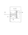
なお、いずれの構成においても、最も物体側にレンズ群Iを配置し、このレンズ群Iに反射光学素子を備えることが好ましい。この反射光学素子は、結像に寄与する光線を折り曲げるために用いられる。このようにすると、光学系の奥行きの薄型化が促進できる。 In any configuration, it is preferable that the lens group I is disposed closest to the object side, and the lens group I includes a reflective optical element. This reflective optical element is used to bend light rays that contribute to image formation. In this way, the reduction in the depth of the optical system can be promoted.
次に、画像処理による歪み補正について以下詳述する。無限遠物体を仮に歪曲収差がない光学系で結像したとする。この場合、結像した像に歪曲がないので、
f=y/tanω …(15)
が成立する。
但し、yは像点の光軸からの高さ、fは結像系の焦点距離、ωは撮像面上の中心からyの位置に結ぶ像点に対応する物点方向の光軸に対する角度である。
Next, distortion correction by image processing will be described in detail below. Assume that an infinite object is imaged by an optical system without distortion. In this case, since the image formed has no distortion,
f = y / tan ω (15)
Is established.
Where y is the height of the image point from the optical axis, f is the focal length of the imaging system, ω is the angle with respect to the optical axis in the object direction corresponding to the image point connecting from the center on the imaging surface to the y position. is there.
一方、光学系に広角端近傍の状態のときのみ樽型歪曲収差を許容した場合は、
f>y/tanω …(16)
となる。つまり、ωとyとを一定の値とするならば、広角端の焦点距離fは長くてよいこととなり、その分収差補正は楽になる。また、前記レンズ群Aに相当するレンズ群を通常2成分以上で構成している理由は歪曲収差と非点収差を両立させるためであるが、それを行う必要がないため、1成分のみで薄く構成することが出来る。
そこで、本発明の電子撮像装置では、電子撮像素子で得られた画像データを、画像処理で加工するようにしている。この加工では、樽型の歪曲収差を補正するように、画像データ(画像の形状)を変化させる。このようにすれば、最終的に得られた画像データは、物体とほぼ相似の形状を持つ画像データとなる。よって、この画像データに基づいて、物体の画像をCRTやプリンターに出力すればよい。
On the other hand, if the barrel distortion is allowed only when the optical system is near the wide-angle end,
f> y / tan ω (16)
It becomes. That is, if ω and y are constant values, the focal length f at the wide-angle end may be long, and the aberration correction becomes easier accordingly. The reason why the lens group corresponding to the lens group A is normally composed of two or more components is to make both distortion and astigmatism compatible, but since it is not necessary to do so, it is thin with only one component. Can be configured.
Therefore, in the electronic imaging apparatus of the present invention, image data obtained by the electronic imaging element is processed by image processing. In this processing, the image data (image shape) is changed so as to correct the barrel distortion. In this way, the finally obtained image data is image data having a shape substantially similar to the object. Therefore, an object image may be output to a CRT or printer based on the image data.
そこで、実施形態の電子撮像装置では、電子撮像素子と、結像光学系を通じて結像した像を電子撮像素子で撮像することによって得られた画像データを加工して像の形状を変化させた画像データとして出力する画像処理手段とを有し、結像光学系がズームレンズであり、ズームレンズが、ほぼ無限遠物点合焦時に次の条件式(17)を満足することが望ましい。
0.70<y07/(fw・tanω07w)<0.97 …(17)
ここで、y07は最大像高をy10としたときy07=0.7y10として表され、ω07wは広角端における撮像面上の中心からy07の位置に結ぶ像点に対応する物点方向の光軸に対する角度である。なお、本実施形態が電子撮像装置の場合、最大像高は、電子撮像素子の有効撮像面内(撮像可能な面内)で中心から最も遠い点までの距離となる。よって、y10も電子撮像素子の有効撮像面内(撮像可能な面内)で中心から最も遠い点までの距離になる。
Therefore, in the electronic imaging device of the embodiment, an image obtained by processing the image data obtained by capturing the image formed by the electronic imaging device and the imaging optical system with the electronic imaging device and changing the shape of the image. Preferably, the image forming optical system is a zoom lens, and the zoom lens satisfies the following conditional expression (17) when focusing on an object point at infinity.
0.70 <y 07 / (fw · tanω 07w) <0.97 ... (17)
Here, y 07 is expressed as y 07 = 0.7y 10 when the maximum image height is y 10, and ω 07w is an object corresponding to the image point connecting from the center on the imaging surface at the wide angle end to the position of y 07 . This is the angle with respect to the optical axis in the point direction. Note that when the present embodiment is an electronic imaging device, the maximum image height is the distance from the center to the farthest point in the effective imaging plane of the electronic imaging element (in the plane where imaging is possible). Accordingly, y 10 becomes the distance to the point farthest from the center in the effective image pickup plane of the electronic imaging device (imaging possible in-plane).
上記条件式(17)はズーム広角端における樽型歪曲の度合いを規定したものである。条件式(17)を満足すれば、無理なく非点収差の補正が可能となる。なお、樽型に歪んだ像は撮像素子にて光電変換されて、樽型に歪んだ画像データとなる。 Conditional expression (17) defines the degree of barrel distortion at the zoom wide-angle end. If conditional expression (17) is satisfied, astigmatism can be corrected without difficulty. Note that an image distorted in a barrel shape is photoelectrically converted by an image sensor to become image data distorted in a barrel shape.
しかしながら、樽型に歪んだ画像データは、電子撮像装置の信号処理系である画像処理手段にて、電気的に、像の形状変化に相当する加工が施される。このようにすれば、最終的に画像処理手段から出力された画像データを表示装置にて再生したとしても、歪曲が補正されて被写体形状にほぼ相似した画像が得られる。 However, the image data distorted into a barrel shape is electrically processed by an image processing means which is a signal processing system of the electronic imaging apparatus, corresponding to a change in the shape of the image. In this way, even if the image data finally output from the image processing means is reproduced on the display device, the distortion is corrected and an image substantially similar to the subject shape is obtained.
ここで、条件式(17)の上限値を上回る場合であって、特に、1に近い値をとると、歪曲収差が光学的に良く補正された画像が得られる。そのため、画像処理手段で行う補正が小さくてすむ。しかしながら、非点収差の補正にとっては有利でなくなる。 Here, when the value exceeds the upper limit value of the conditional expression (17) and takes a value close to 1, an image in which distortion is optically corrected is obtained. Therefore, the correction performed by the image processing means can be small. However, it is not advantageous for correction of astigmatism.
一方、条件式(17)の下限値を下回ると、光学系の歪曲収差による画像歪みを画像処理手段で補正した場合に、画角周辺部の放射方向への引き伸ばし率が高くなりすぎる。その結果、撮像で得た画像において、画像周辺部の鮮鋭度の劣化が目立つようになってしまう。 On the other hand, below the lower limit value of conditional expression (17), when the image distortion due to the distortion of the optical system is corrected by the image processing means, the stretching ratio in the radial direction around the angle of view becomes too high. As a result, in the image obtained by imaging, the sharpness degradation at the periphery of the image becomes conspicuous.
このように、条件式(17)を満足することにより、非点収差が良好に補正しやすくなり、光学系の薄型化と大口径比化(広角端でF/2.8よりも明るくする)の両立が可能となる。 Thus, satisfying conditional expression (17) makes it easy to correct astigmatism favorably, and achieves both a thinner optical system and a larger aperture ratio (brighter than F / 2.8 at the wide-angle end). Is possible.
なお、条件式(17)の代わりに、次の条件式(17')を満足すると、より好ましい。
0.73<y07/(fw・tanω07w)<0.96 …(17')
さらに、条件式(17)の代わりに、次の条件式(17”)を満足すると、より一層好ましい。
0.76<y07/(fw・tanω07w)<0.95 …(17”)
It is more preferable that the following conditional expression (17 ′) is satisfied instead of conditional expression (17).
0.73 <y 07 / (fw · tan ω 07w ) <0.96 (17 ′)
Furthermore, it is more preferable that the following conditional expression (17 ″) is satisfied instead of conditional expression (17).
0.76 <y 07 / (fw · tan ω 07w ) <0.95 (17 ”)
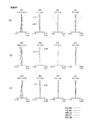
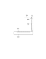
次に、本発明の実施例1にかかるズームレンズについて説明する。図1は本発明の実施例1にかかるズームレンズの無限遠物点合焦時の光学構成を示す光軸に沿う断面図であり、(a)は広角端、(b)は中間焦点距離状態、(c)は望遠端での断面図である。
Next, a zoom lens according to
図2は実施例1にかかるズームレンズの無限遠物点合焦時における球面収差(SA)、非点収差(AS)、歪曲収差(DT)、倍率色収差(CC)を示す図であり、(a)は広角端、(b)は中間焦点距離状態、(c)は望遠端での状態を示している。また、FIYは像高を示している。なお、収差図における記号は、後述の実施例においても共通である。 FIG. 2 is a diagram illustrating spherical aberration (SA), astigmatism (AS), distortion (DT), and lateral chromatic aberration (CC) when the zoom lens according to Example 1 is focused on an object point at infinity. a) shows the wide-angle end, (b) shows the intermediate focal length state, and (c) shows the state at the telephoto end. FIY represents the image height. The symbols in the aberration diagrams are the same in the examples described later.
実施例1のズームレンズは、図1に示すように、物体側より順に、正屈折力の第1レンズ群G1と、負屈折力の第2レンズ群G2と、開口絞りSと、正屈折力の第3レンズ群G3と、正屈折力の第4レンズ群G4を有している。なお、以下全ての実施例において、レンズ断面図中、LPFはローパスフィルター、CGはカバーガラス、Iは電子撮像素子の撮像面を示している。 As shown in FIG. 1, the zoom lens according to the first exemplary embodiment includes, in order from the object side, a first lens group G1 having a positive refractive power, a second lens group G2 having a negative refractive power, an aperture stop S, and a positive refractive power. The third lens group G3 and the fourth lens group G4 having a positive refractive power. In all the following examples, in the lens cross-sectional views, LPF is a low-pass filter, CG is a cover glass, and I is an image pickup surface of an electronic image pickup element.
第1レンズ群G1は、物体側に凸面を向けた正メニスカスレンズL1と正両凸レンズL2との接合レンズで構成されており、全体で正の屈折力を有している。 The first lens group G1 includes a cemented lens of a positive meniscus lens L1 having a convex surface facing the object side and a positive biconvex lens L2, and has a positive refractive power as a whole.
第2レンズ群G2は、物体側に凸面を向けた負メニスカスレンズL3と、像側に凸面を向けた正メニスカスレンズL4と像側に凸面を向けた負メニスカスレンズL5との接合レンズで構成されており、全体で負の屈折力を有している。ここで、像側に凸面を向けた正メニスカスレンズL4がレンズLAで、像側に凸面を向けた負メニスカスレンズL5が負レンズLBである。 The second lens group G2 includes a cemented lens of a negative meniscus lens L3 having a convex surface facing the object side, a positive meniscus lens L4 having a convex surface facing the image side, and a negative meniscus lens L5 having a convex surface facing the image side. And has a negative refractive power as a whole. Here, the positive meniscus lens L4 with the convex surface facing the image side is the lens LA, and the negative meniscus lens L5 with the convex surface facing the image side is the negative lens LB.
第3レンズ群G3は、正両凸レンズL6と、物体側に凸面を向けた正メニスカスレンズL7と物体側に凸面を向けた負メニスカスレンズL8の接合レンズで構成されており、全体で正の屈折力を有している。 The third lens group G3 includes a positive biconvex lens L6, a cemented lens of a positive meniscus lens L7 having a convex surface facing the object side, and a negative meniscus lens L8 having a convex surface facing the object side, and is positively refracted as a whole. Have power.
第4レンズ群G4は、正両凸レンズL9で構成されており、全体で正の屈折力を有している。 The fourth lens group G4 includes a positive biconvex lens L9, and has a positive refractive power as a whole.
広角端から望遠端へと変倍する際には、第1レンズ群G1は中間位置まではほぼ固定(わずかに像側に移動)、中間位置から物体側に移動し、第2レンズ群G2は中間位置まで像側へ移動し、中間位置からは物体側へ移動し、開口絞りSは物体側へ移動し、第3レンズ群G3は物体側へ移動し、第4レンズ群G4は中間位置までは物体側へ移動し、中間位置からは像側へ移動する。 When zooming from the wide-angle end to the telephoto end, the first lens group G1 is substantially fixed to the intermediate position (moved slightly to the image side), moved from the intermediate position to the object side, and the second lens group G2 is It moves to the image side to the intermediate position, moves from the intermediate position to the object side, the aperture stop S moves to the object side, the third lens group G3 moves to the object side, and the fourth lens group G4 moves to the intermediate position. Moves to the object side, and moves from the intermediate position to the image side.
非球面は、第1レンズ群G1中の正両凸レンズL2の像側の面、第2レンズ群G2中の像側に凸面を向けた正メニスカスレンズL4の両面と像側に凸面を向けた負メニスカスレンズL5の像側の面、第3レンズ群G3中の正両凸レンズL6の両面、第4レンズ群G4中の正両凸レンズL9の物体側の面の合計7面に設けられている。 The aspherical surface is a negative image with the convex surface facing the image side surface of the positive biconvex lens L2 in the first lens group G1, both surfaces of the positive meniscus lens L4 with the convex surface facing the image side in the second lens group G2. It is provided on a total of seven surfaces including the image side surface of the meniscus lens L5, both surfaces of the positive biconvex lens L6 in the third lens group G3, and the object side surface of the positive biconvex lens L9 in the fourth lens group G4.
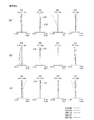
次に、本発明の実施例2にかかるズームレンズについて説明する。図3は本発明の実施例2にかかるズームレンズの無限遠物点合焦時の光学構成を示す光軸に沿う断面図であり、(a)は広角端、(b)は中間焦点距離状態、(c)は望遠端での断面図である。
Next, a zoom lens according to
図4は実施例2にかかるズームレンズの無限遠物点合焦時における球面収差(SA)、非点収差(AS)、歪曲収差(DT)、倍率色収差(CC)を示す図であり、(a)は広角端、(b)は中間焦点距離状態、(c)は望遠端での状態を示している。 FIG. 4 is a diagram illustrating spherical aberration (SA), astigmatism (AS), distortion (DT), and lateral chromatic aberration (CC) when the zoom lens according to Example 2 is focused on an object point at infinity. a) shows the wide-angle end, (b) shows the intermediate focal length state, and (c) shows the state at the telephoto end.
実施例2のズームレンズは、図3に示すように、物体側より順に、正屈折力の第1レンズ群G1と、負屈折力の第2レンズ群G2と、開口絞りSと、正屈折力の第3レンズ群G3と、正屈折力の第4レンズ群G4を有している。 As shown in FIG. 3, the zoom lens according to the second embodiment includes, in order from the object side, a first lens group G1 having a positive refractive power, a second lens group G2 having a negative refractive power, an aperture stop S, and a positive refractive power. The third lens group G3 and the fourth lens group G4 having a positive refractive power.
第1レンズ群G1は、物体側に凸面を向けた負メニスカスレンズL1と物体側に凸面を向けた正メニスカスレンズL2との接合レンズで構成されており、全体で正の屈折力を有している。 The first lens group G1 includes a cemented lens of a negative meniscus lens L1 having a convex surface facing the object side and a positive meniscus lens L2 having a convex surface facing the object side, and has a positive refractive power as a whole. Yes.
第2レンズ群G2は、物体側に凸面を向けた負メニスカスレンズL3と、像側に凸面を向けた正メニスカスレンズL4と負両凹レンズL5との接合レンズと、正両凸レンズL6で構成されており、全体で負の屈折力を有している。ここで、像側に凸面を向けた正メニスカスレンズL4がレンズLAで、負両凹レンズL5が負レンズLBである。 The second lens group G2 includes a negative meniscus lens L3 having a convex surface on the object side, a cemented lens of a positive meniscus lens L4 and a negative biconcave lens L5 having a convex surface on the image side, and a positive biconvex lens L6. And has a negative refractive power as a whole. Here, the positive meniscus lens L4 with the convex surface facing the image side is the lens LA, and the negative biconcave lens L5 is the negative lens LB.
第3レンズ群G3は、正両凸レンズL7と、物体側に凸面を向けた正メニスカスレンズL8と物体側に凸面を向けた負メニスカスレンズL9の接合レンズで構成されており、全体で正の屈折力を有している。 The third lens group G3 includes a positive biconvex lens L7, a cemented lens of a positive meniscus lens L8 having a convex surface facing the object side, and a negative meniscus lens L9 having a convex surface facing the object side, and is positively refracted as a whole. Have power.
第4レンズ群G4は、物体側に凸面を向けた正メニスカスレンズL10で構成されており、全体で正の屈折力を有している。 The fourth lens group G4 includes a positive meniscus lens L10 having a convex surface directed toward the object side, and has a positive refracting power as a whole.
広角端から望遠端へと変倍する際には、第1レンズ群G1は中間位置までは像側へ移動し、中間位置から物体側に移動し、第2レンズ群G2は中間位置まで像側へ移動し、中間位置からは物体側へ移動し、開口絞りSは物体側へ移動し、第3レンズ群G3は物体側へ移動し、第4レンズ群G4は中間位置までは物体側へ移動し、中間位置からは像側へ移動する。 When zooming from the wide angle end to the telephoto end, the first lens group G1 moves to the image side up to the intermediate position, moves from the intermediate position to the object side, and the second lens group G2 moves to the image side up to the intermediate position. To the object side from the intermediate position, the aperture stop S moves to the object side, the third lens group G3 moves to the object side, and the fourth lens group G4 moves to the object side to the intermediate position. Then, it moves to the image side from the intermediate position.
非球面は、第2レンズ群G2中の像側に凸面を向けた負メニスカスレンズL4の両面と負両凹レンズL5の像側の面、第3レンズ群G3中の正両凸レンズL7の両面、第4レンズ群G4中の物体側に凸面を向けた正メニスカスレンズL10の物体側の面の合計6面に設けられている。 The aspherical surface includes both surfaces of a negative meniscus lens L4 having a convex surface facing the image side in the second lens group G2, an image side surface of the negative biconcave lens L5, both surfaces of the positive biconvex lens L7 in the third lens group G3, It is provided on a total of six surfaces on the object side of the positive meniscus lens L10 having a convex surface facing the object side in the four lens group G4.
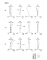
次に、本発明の実施例3にかかるズームレンズについて説明する。図5は本発明の実施例3にかかるズームレンズの無限遠物点合焦時の光学構成を示す光軸に沿う断面図であり、(a)は広角端、(b)は中間焦点距離状態、(c)は望遠端での断面図である。
Next, a zoom lens according to
図6は実施例3にかかるズームレンズの無限遠物点合焦時における球面収差(SA)、非点収差(AS)、歪曲収差(DT)、倍率色収差(CC)を示す図であり、(a)は広角端、(b)は中間焦点距離状態、(c)は望遠端での状態を示している。 FIG. 6 is a diagram illustrating spherical aberration (SA), astigmatism (AS), distortion (DT), and lateral chromatic aberration (CC) when the zoom lens according to Example 3 is focused on an object point at infinity. a) shows the wide-angle end, (b) shows the intermediate focal length state, and (c) shows the state at the telephoto end.
実施例3のズームレンズは、図5に示すように、物体側より順に、正屈折力の第1レンズ群G1と、負屈折力の第2レンズ群G2と、開口絞りSと、正屈折力の第3レンズ群G3と、正屈折力の第4レンズ群G4を有している。 As shown in FIG. 5, the zoom lens of Example 3 includes, in order from the object side, a first lens group G1 having a positive refractive power, a second lens group G2 having a negative refractive power, an aperture stop S, and a positive refractive power. The third lens group G3 and the fourth lens group G4 having a positive refractive power.
第1レンズ群G1は、正両凸レンズL1で構成されており、全体で正の屈折力を有している。 The first lens group G1 is composed of a positive biconvex lens L1, and has a positive refractive power as a whole.
第2レンズ群G2は、負両凹レンズL2と、像側に凸面を向けた正メニスカスレンズL3と負両凹レンズL4との接合レンズとで構成されており、全体で負の屈折力を有している。ここで、像側に凸面を向けた正メニスカスレンズL3がレンズLAで、負両凹レンズL4が負レンズLBである。 The second lens group G2 includes a negative biconcave lens L2, and a cemented lens of a positive meniscus lens L3 having a convex surface facing the image side and a negative biconcave lens L4, and has a negative refractive power as a whole. Yes. Here, the positive meniscus lens L3 with the convex surface facing the image side is the lens LA, and the negative biconcave lens L4 is the negative lens LB.
第3レンズ群G3は、正両凸レンズL5と、物体側に凸面を向けた負メニスカスレンズL6とで構成されており、全体で正の屈折力を有している。 The third lens group G3 includes a positive biconvex lens L5 and a negative meniscus lens L6 having a convex surface directed toward the object side, and has a positive refractive power as a whole.
第4レンズ群G4は、正両凸レンズL7で構成されており、全体で正の屈折力を有している。 The fourth lens group G4 includes a positive biconvex lens L7, and has a positive refractive power as a whole.
広角端から望遠端へと変倍する際には、第1レンズ群G1は物体側へ移動し、第2レンズ群G2はほぼ固定(わずかに物体側へ移動し)、開口絞りSは物体側へ移動し、第3レンズ群G3は物体側へ移動し、第4レンズ群G4は中間位置までは像側へ移動し、中間位置からは物体側へ移動する。 When zooming from the wide-angle end to the telephoto end, the first lens group G1 moves to the object side, the second lens group G2 is substantially fixed (slightly moves to the object side), and the aperture stop S is on the object side. The third lens group G3 moves to the object side, the fourth lens group G4 moves to the image side up to the intermediate position, and moves from the intermediate position to the object side.
非球面は、第1レンズ群G1中の正両凸レンズL1の両面、第2レンズ群G2中の負両凹レンズL2の両面と像側に凸面を向けた正メニスカスレンズL3の両面と負両凹レンズL4の像側の面、第3レンズ群G3中の正両凸レンズL5の両面、第4レンズ群G4中の正両凸レンズL7の物体側の面の合計10面に設けられている。 The aspherical surface includes both surfaces of a positive biconvex lens L1 in the first lens group G1, both surfaces of a negative biconcave lens L2 in the second lens group G2, and both surfaces of a positive meniscus lens L3 having a convex surface facing the image side, and a negative biconcave lens L4. Are provided on a total of ten surfaces including the image side surface, both surfaces of the positive biconvex lens L5 in the third lens group G3, and the object side surface of the positive biconvex lens L7 in the fourth lens group G4.
次に、本発明の実施例4にかかるズームレンズについて説明する。図7は本発明の実施例3にかかるズームレンズの無限遠物点合焦時の光学構成を示す光軸に沿う断面図であり、(a)は広角端、(b)は中間焦点距離状態、(c)は望遠端での断面図である。
Next, a zoom lens according to
図8は実施例4にかかるズームレンズの無限遠物点合焦時における球面収差(SA)、非点収差(AS)、歪曲収差(DT)、倍率色収差(CC)を示す図であり、(a)は広角端、(b)は中間焦点距離状態、(c)は望遠端での状態を示している。 FIG. 8 is a diagram illustrating spherical aberration (SA), astigmatism (AS), distortion (DT), and lateral chromatic aberration (CC) when the zoom lens according to Example 4 is focused on an object point at infinity. a) shows the wide-angle end, (b) shows the intermediate focal length state, and (c) shows the state at the telephoto end.
実施例4のズームレンズは、図7に示すように、物体側より順に、正屈折力の第1レンズ群G1と、負屈折力の第2レンズ群G2と、開口絞りSと、正屈折力の第3レンズ群G3と、正屈折力の第4レンズ群G4を有している。
As shown in FIG. 7, the zoom lens of
第1レンズ群G1は、正両凸レンズL1で構成されており、全体で正の屈折力を有している。 The first lens group G1 is composed of a positive biconvex lens L1, and has a positive refractive power as a whole.
第2レンズ群G2は、負両凹レンズL2と、負両凹レンズL3と物体側に凸面を向けた正メニスカスレンズL4との接合レンズとで構成されており、全体で負の屈折力を有している。ここで、物体側に凸面を向けた正メニスカスレンズL4がレンズLAで、負両凹レンズL3が負レンズLBである。 The second lens group G2 includes a negative biconcave lens L2, a cemented lens of a negative biconcave lens L3 and a positive meniscus lens L4 having a convex surface facing the object side, and has a negative refractive power as a whole. Yes. Here, the positive meniscus lens L4 with the convex surface facing the object side is the lens LA, and the negative biconcave lens L3 is the negative lens LB.
第3レンズ群G3は、正両凸レンズL5と、物体側に凸面を向けた負メニスカスレンズL6とで構成されており、全体で正の屈折力を有している。 The third lens group G3 includes a positive biconvex lens L5 and a negative meniscus lens L6 having a convex surface directed toward the object side, and has a positive refractive power as a whole.
第4レンズ群G4は、像側に凸面を向けた負メニスカスレンズL7で構成されており、全体で正の屈折力を有している。 The fourth lens group G4 includes a negative meniscus lens L7 having a convex surface directed toward the image side, and has a positive refracting power as a whole.
広角端から望遠端へと変倍する際には、第1レンズ群G1は物体側へ移動し、第2レンズ群G2は物体側へ移動し、開口絞りSは物体側へ移動し、第3レンズ群G3は物体側へ移動し、第4レンズ群G4は中間位置までは像側へ移動し、中間位置からは固定している。 When zooming from the wide-angle end to the telephoto end, the first lens group G1 moves to the object side, the second lens group G2 moves to the object side, the aperture stop S moves to the object side, The lens group G3 moves to the object side, and the fourth lens group G4 moves to the image side up to the intermediate position and is fixed from the intermediate position.
非球面は、第1レンズ群G1中の正両凸レンズL1の両面、第2レンズ群G2中の負両凹レンズL2の両面と負両凹レンズL3の両面と物体側に凸面を向けた正メニスカスレンズL4の像側の面、第3レンズ群G3中の正両凸レンズL5の両面、第4レンズ群G4中の像側に凸面を向けた負メニスカスレンズL7の物体側の面の合計10面に設けられている。 The aspherical surface is a positive meniscus lens L4 having convex surfaces facing both surfaces of the positive biconvex lens L1 in the first lens group G1, both surfaces of the negative biconcave lens L2 and both surfaces of the negative biconcave lens L3, and the object side in the second lens group G2. Image side surfaces, both surfaces of the positive biconvex lens L5 in the third lens group G3, and the object side surfaces of the negative meniscus lens L7 having a convex surface facing the image side in the fourth lens group G4. ing.
次に、上記各実施例のズームレンズを構成する光学部材の数値データを掲げる。なお、各実施例の数値データにおいて、r1、r2、…は各レンズ面の曲率半径、d1、d2、…は各レンズの肉厚または空気間隔、nd1、nd2、…は各レンズのd線での屈折率、νd1、νd2、…は各レンズのアッべ数、Fno.はFナンバー、fは全系焦点距離、D0は物体から第1面までの距離をそれぞれ表している。また、*は非球面、STOは絞りをそれぞれ示している。 Next, numerical data of optical members constituting the zoom lens of each of the above embodiments will be listed. In the numerical data of each embodiment, r1, r2,... Are the radius of curvature of each lens surface, d1, d2,. Are the Abbe number of each lens, Fno. Is the F number, f is the focal length of the entire system, and D0 is the distance from the object to the first surface. * Indicates an aspherical surface, and STO indicates an aperture.
また、非球面形状は、光軸方向をz、光軸に直交する方向をyにとり、円錐係数をK、非球面係数をA4、A6、A8、A10としたとき、次の式で表される。
z=(y2/r)/[1+{1−(1+K)(y/r)2}1/2]
+A4y4+A6y6+A8y8+A10y10
また、Eは10のべき乗を表している。なお、これら諸元値の記号は後述の実施例の数値データにおいても共通である。
The aspherical shape is expressed by the following equation when the optical axis direction is z, the direction orthogonal to the optical axis is y, the conical coefficient is K, and the aspherical coefficients are A4, A6, A8, and A10. .
z = (y 2 / r) / [1+ {1− (1 + K) (y / r) 2 } 1/2 ]
+ A4y 4 + A6y 6 + A8y 8 + A10y 10
E represents a power of 10. Note that the symbols of these specification values are also common in the numerical data of the examples described later.
(数値実施例1)
単位 mm
面データ
面番号 r d nd νd
物面 ∞ ∞
1 26.4450 0.8000 1.84666 23.78
2 13.8156 2.7000 1.73077 40.51
3* -192.7244 可変
4 43.7694 0.7000 1.69680 55.53
5 10.8906 2.2000
6* -15.3637 1.0000 1.63494 23.22
7* -6.7944 0.9000 1.74320 49.34
8* -208.0010 可変
9(絞り) ∞ 可変
10* 24.1688 1.8000 1.74250 49.20
11* -19.2188 0.1500
12 5.4497 2.7000 1.69680 55.53
13 13.4248 0.6000 1.84666 23.78
14 4.2048 可変
15* 10.9456 2.0000 1.58313 59.46
16 -35.4704 可変
17 ∞ 0.7580 1.54771 62.84
18 ∞ 0.4787
19 ∞ 0.3989 1.51633 64.14
20 ∞ 1.3603
像面 ∞
非球面データ
第3面
K=-0.1059,
A2=0.0000E+00,A4=3.4600E-07,A6=4.6678E-09,A8=0.0000E+00,A10=0.0000E+00
第6面
K=-0.6957,
A2=0.0000E+00,A4=-1.2458E-04 ,A6=3.0542E-06,A8=0.0000E+00,A10=0.0000E+00
第7面
K=-0.7528,
A2=0.0000E+00,A4=-4.3041E-04,A6=2.1935E-05,A8=0.0000E+00,A10=0.0000E+00
第8面
K=-0.9690,
A2=0.0000E+00,A4=-1.3472E-04,A6=7.2254E-06,A8=0.0000E+00,A10=0.0000E+00
第10面
K=3.7659,
A2=0.0000E+00,A4=-3.8282E-04,A6=1.5704E-05,A8=0.0000E+00,A10=0.0000E+00
第11面
K=-0.9658,
A2=0.0000E+00,A4=-2.2045E-04,A6=1.4126E-05,A8= 0.0000E+00,A10=0.0000E+00
第15面
K=-0.9236,
A2=0.0000E+00,A4=3.1124E-05,A6=2.9451E-07,A8=0.0000E+00,A10=0.0000E+00
各種データ
ズーム比
広角 中間 望遠
焦点距離 7.00943 15.64607 35.00249
Fno. 2.8400 2.9504 3.8784
画角 30.3° 12.9° 5.8°
像高 3.6 3.6 3.6
レンズ全長 46.9634 45.9916 55.4100
BF 1.36028 1.35268 1.35989
d3 0.65000 8.83784 14.65673
d8 17.19034 6.04002 1.50167
d9 0.80000 0.79787 0.79787
d14 7.65597 6.42400 15.77566
d16 2.12115 5.35351 4.13256
ズームレンズ群データ
群 始面 焦点距離
1 1 36.57282
2 4 -9.33696
3 10 12.64978
4 15 14.57546
〔硝材屈折率テーブル〕・・・ 本実施例にて使用した媒質の波長別屈折率一覧
GLA 587.56 656.27 486.13 435.84 404.66
L6 1.742499 1.737967 1.753057 1.761415 1.768384
L10 1.547710 1.545046 1.553762 1.558427 1.562262
L4 1.634940 1.627290 1.654640 1.674080 1.693923
L2 1.730770 1.725416 1.743456 1.753787 1.762674
L9 1.583130 1.580140 1.589950 1.595245 1.599635
L11 1.516330 1.513855 1.521905 1.526213 1.529768
L3,L7 1.696797 1.692974 1.705522 1.712339 1.718005
L5 1.743198 1.738653 1.753716 1.762046 1.769040
L1,L8 1.846660 1.836488 1.872096 1.894186 1.914294
各面の非球面量
第6面
Y ASP SPH ΔzA(h)
3.228 -0.35033 -0.34294 -0.00739
第8面
Y ASP SPH ΔzB(h)
3.228 -0.03150 -0.02505 -0.00645
第7面
Y ASP SPH ΔzC(h)
3.228 -0.79972 -0.81577 0.01605
(Numerical example 1)
Unit mm
Surface data surface number rd nd νd
Object ∞ ∞
1 26.4450 0.8000 1.84666 23.78
2 13.8156 2.7000 1.73077 40.51
3 * -192.7244 Variable
4 43.7694 0.7000 1.69680 55.53
5 10.8906 2.2000
6 * -15.3637 1.0000 1.63494 23.22
7 * -6.7944 0.9000 1.74320 49.34
8 * -208.0010 Variable
9 (Aperture) ∞ Variable
10 * 24.1688 1.8000 1.74250 49.20
11 * -19.2188 0.1500
12 5.4497 2.7000 1.69680 55.53
13 13.4248 0.6000 1.84666 23.78
14 4.2048 Variable
15 * 10.9456 2.0000 1.58313 59.46
16 -35.4704 Variable
17 ∞ 0.7580 1.54771 62.84
18 ∞ 0.4787
19 ∞ 0.3989 1.51633 64.14
20 ∞ 1.3603
Image plane ∞
Aspheric data 3rd surface
K = -0.1059,
A2 = 0.0000E + 00, A4 = 3.4600E-07, A6 = 4.6678E-09, A8 = 0.0000E + 00, A10 = 0.0000E + 00
6th page
K = -0.6957,
A2 = 0.0000E + 00, A4 = -1.2458E-04, A6 = 3.0542E-06, A8 = 0.0000E + 00, A10 = 0.0000E + 00
7th page
K = -0.7528,
A2 = 0.0000E + 00, A4 = -4.3041E-04, A6 = 2.1935E-05, A8 = 0.0000E + 00, A10 = 0.0000E + 00
8th page
K = -0.9690,
A2 = 0.0000E + 00, A4 = -1.3472E-04, A6 = 7.2254E-06, A8 = 0.0000E + 00, A10 = 0.0000E + 00
10th page
K = 3.7659,
A2 = 0.0000E + 00, A4 = -3.8282E-04, A6 = 1.5704E-05, A8 = 0.0000E + 00, A10 = 0.0000E + 00
11th page
K = -0.9658,
A2 = 0.0000E + 00, A4 = -2.2045E-04, A6 = 1.4126E-05, A8 = 0.0000E + 00, A10 = 0.0000E + 00
15th page
K = -0.9236,
A2 = 0.0000E + 00, A4 = 3.1124E-05, A6 = 2.9451E-07, A8 = 0.0000E + 00, A10 = 0.0000E + 00
Various data zoom ratios
Wide angle Medium telephoto focal length 7.00943 15.64607 35.00249
Fno. 2.8400 2.9504 3.8784
Angle of view 30.3 ° 12.9 ° 5.8 °
Image height 3.6 3.6 3.6
Total lens length 46.9634 45.9916 55.4100
BF 1.36028 1.35268 1.35989
d3 0.65000 8.83784 14.65673
d8 17.19034 6.04002 1.50167
d9 0.80000 0.79787 0.79787
d14 7.65597 6.42400 15.77566
d16 2.12115 5.35351 4.13256
Zoom lens group data group Start surface Focal length
1 1 36.57282
2 4 -9.33696
3 10 12.64978
4 15 14.57546
[Glass Material Refractive Index Table] ... List of refractive indexes by wavelength of the medium used in this example
GLA 587.56 656.27 486.13 435.84 404.66
L6 1.742499 1.737967 1.753057 1.761415 1.768384
L10 1.547710 1.545046 1.553762 1.558427 1.562262
L4 1.634940 1.627290 1.654640 1.674080 1.693923
L2 1.730770 1.725416 1.743456 1.753787 1.762674
L9 1.583130 1.580140 1.589950 1.595245 1.599635
L11 1.516330 1.513855 1.521905 1.526213 1.529768
L3, L7 1.696797 1.692974 1.705522 1.712339 1.718005
L5 1.743198 1.738653 1.753716 1.762046 1.769040
L1, L8 1.846660 1.836488 1.872096 1.894186 1.914294
Aspherical surface 6th surface of each surface
Y ASP SPH ΔzA (h)
3.228 -0.35033 -0.34294 -0.00739
8th page
Y ASP SPH ΔzB (h)
3.228 -0.03150 -0.02505 -0.00645
7th page
Y ASP SPH ΔzC (h)
3.228 -0.79972 -0.81577 0.01605
数値実施例2
単位 mm
面データ
面番号 r d nd νd
物面 ∞ ∞
1 26.8390 0.6000 1.84666 23.78
2 16.3344 3.8000 1.72000 43.69
3 251.2140 可変
4 79.0802 0.8000 1.88300 38.50
5 10.4013 3.9000
6* -15.6402 0.5000 1.63494 23.22
7* -11.2194 0.8000 1.83481 42.71
8* 2.084E+04 0.2000
9 29.3362 2.0000 1.80810 22.76
10 -42.8587 可変
11(絞り) ∞ 0.4000
12* 12.5777 1.8000 1.69350 51.80
13* -87.4358 0.2000
14 5.3985 2.4000 1.49700 81.54
15 9.5055 0.8000 1.84666 23.78
16 4.5362 可変
17* 14.1406 1.6000 1.69350 53.18
18 39.9405 可変
19 ∞ 0.9010 1.54771 62.84
20 ∞ 0.5300
21 ∞ 0.5300 1.51633 64.14
22 ∞ 1.3601
像面 ∞
非球面データ
第6面
K=-0.0535,
A2=0.0000E+00,A4=3.4485E-05,A6=-3.6491E-08,A8=0.0000E+00,A10=0.0000E+00
第7面
K=-0.1837,
A2=0.0000E+00,A4=-6.5454E-06,A6=4.1099E-06,A8=0.0000E+00,A10=0.0000E+00
第8面
K=8.5769,
A2=0.0000E+00,A4=6.0909E-05,A6=5.5779E-07,A8=0.0000E+00,A10=0.0000E+00
第12面
K=-0.6890,
A2=0.0000E+00,A4=1.0899E-04,A6=1.6473E-05,A8=3.5467E-07,A10=0.0000E+00
第13面
K=0,
A2=0.0000E+00,A4=1.9328E-04,A6=1.9010E-05,A8=4.8815E-07,A10=0.0000E+00
第17面
K=0,
A2=0.0000E+00,A4=-1.2785E-05,A6=6.0991E-07,A8=-2.5404E-09,A10=0.0000E+00
各種データ
ズーム比
広角 中間 望遠
焦点距離 6.99897 19.80013 56.00002
Fno. 3.1000 3.7979 5.0423
画角 31.7° 10.9° 3.8°
像高 3.8 3.8 3.8
レンズ全長 67.2592 58.2183 71.9432
BF 1.36011 1.36035 1.36027
d3 0.59976 10.08933 22.11095
d10 31.33058 8.25005 1.59000
d16 7.69341 5.84941 21.84350
d18 4.51433 10.90817 3.27745
ズームレンズ群データ
群 始面 焦点距離
1 1 47.20195
2 4 -12.34780
3 12 17.08297
4 17 30.78406
〔硝材屈折率テーブル〕・・・ 本実施例にて使用した媒質の波長別屈折率一覧
GLA 587.56 656.27 486.13 435.84 404.66
L7 1.693499 1.689469 1.702855 1.710240 1.716386
L3 1.882998 1.876228 1.899160 1.912305 1.923515
L11 1.547710 1.545046 1.553762 1.558427 1.562261
L4 1.634940 1.627290 1.654640 1.673656 1.692736
L10 1.693500 1.689551 1.702591 1.709739 1.715701
L12 1.516330 1.513855 1.521905 1.526213 1.529768
L8 1.496999 1.495136 1.501231 1.504506 1.507205
L5 1.834807 1.828975 1.848520 1.859547 1.868911
L2 1.720000 1.715105 1.731585 1.740976 1.749012
L6 1.808095 1.798009 1.833513 1.855902 1.876580
L1,L9 1.846660 1.836488 1.872096 1.894186 1.914294
各面の非球面量
第6面
Y ASP SPH ΔzA(h)
4.658 -0.69297 -0.70973 0.01676
第8面
Y ASP SPH ΔzB(h)
4.658 0.03489 0.00052 0.03437
第7面
Y ASP SPH ΔzC(h)
4.658 -0.96468 -1.01264 0.04796
Numerical example 2
Unit mm
Surface data surface number rd nd νd
Object ∞ ∞
1 26.8390 0.6000 1.84666 23.78
2 16.3344 3.8000 1.72000 43.69
3 251.2140 Variable
4 79.0802 0.8000 1.88300 38.50
5 10.4013 3.9000
6 * -15.6402 0.5000 1.63494 23.22
7 * -11.2194 0.8000 1.83481 42.71
8 * 2.084E + 04 0.2000
9 29.3362 2.0000 1.80810 22.76
10 -42.8587 Variable
11 (Aperture) ∞ 0.4000
12 * 12.5777 1.8000 1.69350 51.80
13 * -87.4358 0.2000
14 5.3985 2.4000 1.49700 81.54
15 9.5055 0.8000 1.84666 23.78
16 4.5362 Variable
17 * 14.1406 1.6000 1.69350 53.18
18 39.9405 Variable
19 ∞ 0.9010 1.54771 62.84
20 ∞ 0.5300
21 ∞ 0.5300 1.51633 64.14
22 ∞ 1.3601
Image plane ∞
Aspheric data 6th surface
K = -0.0535,
A2 = 0.0000E + 00, A4 = 3.4485E-05, A6 = -3.6491E-08, A8 = 0.0000E + 00, A10 = 0.0000E + 00
7th page
K = -0.1837,
A2 = 0.0000E + 00, A4 = -6.5454E-06, A6 = 4.1099E-06, A8 = 0.0000E + 00, A10 = 0.0000E + 00
8th page
K = 8.5769,
A2 = 0.0000E + 00, A4 = 6.0909E-05, A6 = 5.5779E-07, A8 = 0.0000E + 00, A10 = 0.0000E + 00
12th page
K = -0.6890,
A2 = 0.0000E + 00, A4 = 1.0899E-04, A6 = 1.6473E-05, A8 = 3.5467E-07, A10 = 0.0000E + 00
13th page
K = 0,
A2 = 0.0000E + 00, A4 = 1.9328E-04, A6 = 1.9010E-05, A8 = 4.8815E-07, A10 = 0.0000E + 00
17th page
K = 0,
A2 = 0.0000E + 00, A4 = -1.2785E-05, A6 = 6.0991E-07, A8 = -2.5404E-09, A10 = 0.0000E + 00
Various data zoom ratios
Wide angle Medium telephoto focal length 6.99897 19.80013 56.00002
Fno. 3.1000 3.7979 5.0423
Angle of view 31.7 ° 10.9 ° 3.8 °
Image height 3.8 3.8 3.8
Total lens length 67.2592 58.2183 71.9432
BF 1.36011 1.36035 1.36027
d3 0.59976 10.08933 22.11095
d10 31.33058 8.25005 1.59000
d16 7.69341 5.84941 21.84350
d18 4.51433 10.90817 3.27745
Zoom lens group data group Start surface Focal length
1 1 47.20195
2 4 -12.34780
3 12 17.08297
4 17 30.78406
[Glass Material Refractive Index Table] ... List of refractive indexes by wavelength of the medium used in this example
GLA 587.56 656.27 486.13 435.84 404.66
L7 1.693499 1.689469 1.702855 1.710240 1.716386
L3 1.882998 1.876228 1.899160 1.912305 1.923515
L11 1.547710 1.545046 1.553762 1.558427 1.562261
L4 1.634940 1.627290 1.654640 1.673656 1.692736
L10 1.693500 1.689551 1.702591 1.709739 1.715701
L12 1.516330 1.513855 1.521905 1.526213 1.529768
L8 1.496999 1.495136 1.501231 1.504506 1.507205
L5 1.834807 1.828975 1.848520 1.859547 1.868911
L2 1.720000 1.715105 1.731585 1.740976 1.749012
L6 1.808095 1.798009 1.833513 1.855902 1.876580
L1, L9 1.846660 1.836488 1.872096 1.894186 1.914294
Aspherical surface 6th surface of each surface
Y ASP SPH ΔzA (h)
4.658 -0.69297 -0.70973 0.01676
8th page
Y ASP SPH ΔzB (h)
4.658 0.03489 0.00052 0.03437
7th page
Y ASP SPH ΔzC (h)
4.658 -0.96468 -1.01264 0.04796
数値実施例3
単位 mm
面データ
面番号 r d nd νd
物面 ∞ ∞
1* 16.4189 2.2423 1.49700 81.54
2* -49.9548 可変
3* -40.0473 0.7000 1.52542 50.50
4* 7.1803 1.3239
5* -129.9255 0.5752 1.63494 23.22
6* -19.3026 0.8000 1.58313 59.38
7* 16.3014 可変
8(絞り) ∞ -0.1000
9* 4.4912 1.9000 1.74320 49.34
10* -40.0312 0.1000
11 6.2476 1.1000 1.92286 20.10
12 2.9815 可変
13* 37.0133 2.4341 1.52542 55.78
14 -9.2906 可変
15 ∞ 1.0000 1.51633 64.14
16 ∞ 1.2014
像面 ∞
非球面データ
第1面
K=-0.9358,
A2=0.0000E+00,A4=1.7221E-05,A6=-8.4549E-07,A8=2.0978E-08,A10=-3.8409E-11
第2面
K=-1.4315,
A2=0.0000E+00,A4=1.7746E-06,A6=4.2666E-08,A8=1.7609E-08,A10=-1.8044E-10
第3面
K=8.5291,
A2=0.0000E+00,A4=-9.1235E-04,A6=3.3157E-05,A8=-5.2667E-07,A10=4.2126E-09
第4面
K=-1.6973,
A2=0.0000E+00,A4=6.6240E-04,A6=-4.9690E-06,A8=-1.8842E-06,A10=3.4072E-08
第5面
K=122.9470,
A2=0.0000E+00,A4=1.2621E-03,A6=-6.1794E-05,A8=0.0000E+00,A10=0.0000E+00
第6面
K=0,
A2=0.0000E+00,A4=6.0000E-04,A6=-3.0000E-05,A8=0.0000E+00,A10=0.0000E+00
第7面
K=0,
A2=0.0000E+00,A4= 0.0000E+00,A6=-2.0000E-05,A8=0.0000E+00,A10=0.0000E+00
第9面
K=-0.8591,
A2=0.0000E+00,A4=1.0435E-04,A6=-1.1049E-07,A8=-1.9982E-06,A10=-2.4152E-07
第10面
K=29.2890,
A2=0.0000E+00,A4=4.4251E-04,A6=-4.6420E-05,A8=-4.3674E-07,A10=0.0000E+00
第13面
K=-4.9538,
A2=0.0000E+00,A4=-2.0035E-05,A6=4.9528E-06,A8=-2.3417E-07,A10=3.0514E-09
各種データ
ズーム比
広角 中間 望遠
焦点距離 6.77084 12.45173 25.40909
Fno. 3.6000 4.5950 5.4487
画角 32.8° 17.6° 8.9°
像高 3.84 3.84 3.84
レンズ全長 31.5188 34.7815 38.2644
BF 1.20139 1.20499 1.19426
d2 0.46811 3.55999 6.84730
d7 10.58492 6.65979 0.80013
d12 3.53462 8.16389 11.69102
d14 3.65428 3.11734 5.65619
ズームレンズ群データ
群 始画 焦点距離
1 1 25.14596
2 3 -7.57674
3 9 9.61953
4 13 14.39503
〔硝材屈折率テーブル〕・・・ 本実施例にて使用した媒質の波長別屈折率一覧
GLA 587.56 656.27 486.13 435.84 404.66
L2 1.525419 1.522301 1.532704 1.538508 1.543381
L6 1.922856 1.909932 1.955840 1.984877 2.011316
L3 1.634940 1.627290 1.654640 1.675524 1.697965
L4 1.583126 1.580139 1.589960 1.595296 1.599721
L8 1.516330 1.513855 1.521905 1.526213 1.529768
L1 1.496999 1.495136 1.501231 1.504506 1.507205
L5 1.743198 1.738653 1.753716 1.762046 1.769040
L7 1.525420 1.522680 1.532100 1.537050 1.540699
各面の非球面量
第5面
Y ASP SPH ΔzA(h)
3.128 0.02458 -0.03766 0.06224
第7面
Y ASP SPH ΔzB(h)
3.128 0.28419 0.30292 -0.01873
第6面
Y ASP SPH ΔzC(h)
3.128 -0.22579 -0.25513 0.02934
Numerical Example 3
Unit mm
Surface data surface number rd nd νd
Object ∞ ∞
1 * 16.4189 2.2423 1.49700 81.54
2 * -49.9548 variable
3 * -40.0473 0.7000 1.52542 50.50
4 * 7.1803 1.3239
5 * -129.9255 0.5752 1.63494 23.22
6 * -19.3026 0.8000 1.58313 59.38
7 * 16.3014 variable
8 (Aperture) ∞ -0.1000
9 * 4.4912 1.9000 1.74320 49.34
10 * -40.0312 0.1000
11 6.2476 1.1000 1.92286 20.10
12 2.9815 Variable
13 * 37.0133 2.4341 1.52542 55.78
14 -9.2906 Variable
15 ∞ 1.0000 1.51633 64.14
16 ∞ 1.2014
Image plane ∞
Aspheric data first surface
K = -0.9358,
A2 = 0.0000E + 00, A4 = 1.7221E-05, A6 = -8.4549E-07, A8 = 2.0978E-08, A10 = -3.8409E-11
Second side
K = -1.4315,
A2 = 0.0000E + 00, A4 = 1.7746E-06, A6 = 4.2666E-08, A8 = 1.7609E-08, A10 = -1.8044E-10
Third side
K = 8.5291,
A2 = 0.0000E + 00, A4 = -9.1235E-04, A6 = 3.3157E-05, A8 = -5.2667E-07, A10 = 4.2126E-09
4th page
K = -1.6973,
A2 = 0.0000E + 00, A4 = 6.6240E-04, A6 = -4.9690E-06, A8 = -1.8842E-06, A10 = 3.4072E-08
5th page
K = 122.9470,
A2 = 0.0000E + 00, A4 = 1.2621E-03, A6 = -6.1794E-05, A8 = 0.0000E + 00, A10 = 0.0000E + 00
6th page
K = 0,
A2 = 0.0000E + 00, A4 = 6.0000E-04, A6 = -3.0000E-05, A8 = 0.0000E + 00, A10 = 0.0000E + 00
7th page
K = 0,
A2 = 0.0000E + 00, A4 = 0.0000E + 00, A6 = -2.0000E-05, A8 = 0.0000E + 00, A10 = 0.0000E + 00
9th page
K = -0.8591,
A2 = 0.0000E + 00, A4 = 1.0435E-04, A6 = -1.1049E-07, A8 = -1.9982E-06, A10 = -2.4152E-07
10th page
K = 29.2890,
A2 = 0.0000E + 00, A4 = 4.4251E-04, A6 = -4.6420E-05, A8 = -4.3674E-07, A10 = 0.0000E + 00
13th page
K = -4.9538,
A2 = 0.0000E + 00, A4 = -2.0035E-05, A6 = 4.9528E-06, A8 = -2.3417E-07, A10 = 3.0514E-09
Various data zoom ratios
Wide angle Medium telephoto focal length 6.77084 12.45173 25.40909
Fno. 3.6000 4.5950 5.4487
Angle of view 32.8 ° 17.6 ° 8.9 °
Image height 3.84 3.84 3.84
Total lens length 31.5188 34.7815 38.2644
BF 1.20139 1.20499 1.19426
d2 0.46811 3.55999 6.84730
d7 10.58492 6.65979 0.80013
d12 3.53462 8.16389 11.69102
d14 3.65428 3.11734 5.65619
Zoom lens group data group Initial image Focal length
1 1 25.14596
2 3 -7.57674
3 9 9.61953
4 13 14.39503
[Glass Material Refractive Index Table] ... List of refractive indexes by wavelength of the medium used in this example
GLA 587.56 656.27 486.13 435.84 404.66
L2 1.525419 1.522301 1.532704 1.538508 1.543381
L6 1.922856 1.909932 1.955840 1.984877 2.011316
L3 1.634940 1.627290 1.654640 1.675524 1.697965
L4 1.583126 1.580139 1.589960 1.595296 1.599721
L8 1.516330 1.513855 1.521905 1.526213 1.529768
L1 1.496999 1.495136 1.501231 1.504506 1.507205
L5 1.743198 1.738653 1.753716 1.762046 1.769040
L7 1.525420 1.522680 1.532100 1.537050 1.540699
Aspherical surface 5th surface of each surface
Y ASP SPH ΔzA (h)
3.128 0.02458 -0.03766 0.06224
7th page
Y ASP SPH ΔzB (h)
3.128 0.28419 0.30292 -0.01873
6th page
Y ASP SPH ΔzC (h)
3.128 -0.22579 -0.25513 0.02934
数値実施例4
単位 mm
面データ
面番号 r d nd νd
物面 ∞ ∞
1* 16.7505 2.3212 1.49700 81.54
2* -34.9627 可変
3* -22.8401 0.7000 1.52542 55.78
4* 6.4242 1.8740
5* -21.1421 0.8000 1.58313 59.38
6* 17.8005 0.6046 1.63494 19.00
7* 131.5083 可変
8(絞り) ∞ -0.1000
9* 4.3682 1.8843 1.74320 49.34
10* -63.9755 0.1000
11 5.7772 1.1000 1.92286 18.90
12 2.9400 可変
13* -166.6984 2.3259 1.52542 45.00
14 -8.1475 可変
15 ∞ 1.0000 1.51633 64.14
16 ∞ 1.0793
像面 ∞
非球面データ
第1面
K=0.2390,
A2=0.0000E+00,A4=-7.2413E-06,A6=-4.0959E-06,A8=6.1260E-11,A10=-2.3019E-09
第2面
K=4.6801,
A2=0.0000E+00,A4=8.0872E-05,A6=-3.3793E-06,A8=-1.8316E-07,A10=2.9694E-09
第3面
K=1.9022,
A2=0.0000E+00,A4=-6.0586E-04,A6=6.1661E-05,A8=-2.1406E-06,A10=2.6928E-08
第4面
K=-0.0906,
A2=0.0000E+00,A4=-6.5916E-04,A6=5.0762E-05,A8=2.5205E-06,A10=-1.1728E-07
第5面
K=0,
A2=0.0000E+00,A4=3.2402E-04,A6=8.4797E-06,A8=0.0000E+00,A10=0.0000E+00
第6面
K=0,
A2=0.0000E+00,A4=-6.0000E-04,A6=0.0000E+00,A8=0.0000E+00,A10=0.0000E+00
第7面
K=7.1865,
A2=0.0000E+00,A4=-1.6000E-04,A6=0.0000E+00,A8=0.0000E+00,A10=0.0000E+00
第9面
K=-3.0231,
A2=0.0000E+00,A4=3.6716E-03,A6=-1.3025E-04,A8=1.2545E-05,A10=-3.0304E-07
第10面
K=-1.4301,
A2=0.0000E+00,A4=8.5325E-04,A6=2.7829E-05,A8=4.3372E-06,A10=0.0000E+00
第13面
K=9.6449,
A2=0.0000E+00,A4=-3.3648E-04,A6=2.1031E-05,A8=-8.7568E-07,A10=1.2082E-08
各種データ
ズーム比
広角 中間 望遠
焦点距離 6.45208 12.51638 25.49743
Fno. 2.9708 4.1804 5.6000
画角 34.1° 17.5° 8.8°
像高 3.84 3.84 3.84
レンズ全長 30.2791 33.2572 38.7555
BF 1.07930 1.13084 1.06664
d2 0.31924 2.25737 5.02792
d7 9.45827 5.36130 1.34833
d12 2.77791 9.11561 15.30831
d14 4.03440 2.78209 3.39431
ズームレンズ群データ
群 始画 焦点距離
1 1 23.13109
2 3 -7.05803
3 9 8.95029
4 13 16.22159
〔硝材屈折率テーブル〕・・・ 本実施例にて使用した媒質の波長別屈折率一覧
GLA 587.56 656.27 486.13 435.84 404.66
L7 1.525419 1.521949 1.533624 1.540248 1.545870
L4 1.634937 1.625875 1.659289 1.682219 1.704243
L3 1.583126 1.580139 1.589960 1.595296 1.599721
L8 1.516330 1.513855 1.521905 1.526213 1.529768
L1 1.496999 1.495136 1.501231 1.504506 1.507205
L5 1.743198 1.738653 1.753716 1.762046 1.769040
L6 1.922860 1.909158 1.957996 1.989713 2.019763
L2 1.525420 1.522680 1.532100 1.537050 1.540699
各面の非球面量
第7面
Y ASP SPH ΔzA(h)
3.410 0.02264 0.04422 -0.02158
第5面
Y ASP SPH ΔzB(h)
3.410 -0.21967 -0.27681 0.05714
第6面
Y ASP SPH ΔzC(h)
3.410 0.24855 0.32968 -0.08113
Numerical Example 4
Unit mm
Surface data surface number rd nd νd
Object ∞ ∞
1 * 16.7505 2.3212 1.49700 81.54
2 * -34.9627 Variable
3 * -22.8401 0.7000 1.52542 55.78
4 * 6.4242 1.8740
5 * -21.1421 0.8000 1.58313 59.38
6 * 17.8005 0.6046 1.63494 19.00
7 * 131.5083 Variable
8 (Aperture) ∞ -0.1000
9 * 4.3682 1.8843 1.74320 49.34
10 * -63.9755 0.1000
11 5.7772 1.1000 1.92286 18.90
12 2.9400 Variable
13 * -166.6984 2.3259 1.52542 45.00
14 -8.1475 Variable
15 ∞ 1.0000 1.51633 64.14
16 ∞ 1.0793
Image plane ∞
Aspheric data first surface
K = 0.2390,
A2 = 0.0000E + 00, A4 = -7.2413E-06, A6 = -4.0959E-06, A8 = 6.1260E-11, A10 = -2.3019E-09
Second side
K = 4.6801,
A2 = 0.0000E + 00, A4 = 8.0872E-05, A6 = -3.3793E-06, A8 = -1.8316E-07, A10 = 2.9694E-09
Third side
K = 1.9022,
A2 = 0.0000E + 00, A4 = -6.0586E-04, A6 = 6.1661E-05, A8 = -2.1406E-06, A10 = 2.6928E-08
4th page
K = -0.0906,
A2 = 0.0000E + 00, A4 = -6.5916E-04, A6 = 5.0762E-05, A8 = 2.5205E-06, A10 = -1.1728E-07
5th page
K = 0,
A2 = 0.0000E + 00, A4 = 3.2402E-04, A6 = 8.4797E-06, A8 = 0.0000E + 00, A10 = 0.0000E + 00
6th page
K = 0,
A2 = 0.0000E + 00, A4 = -6.0000E-04, A6 = 0.0000E + 00, A8 = 0.0000E + 00, A10 = 0.0000E + 00
7th page
K = 7.1865,
A2 = 0.0000E + 00, A4 = -1.6000E-04, A6 = 0.0000E + 00, A8 = 0.0000E + 00, A10 = 0.0000E + 00
9th page
K = -3.0231,
A2 = 0.0000E + 00, A4 = 3.6716E-03, A6 = -1.3025E-04, A8 = 1.2545E-05, A10 = -3.0304E-07
10th page
K = -1.4301,
A2 = 0.0000E + 00, A4 = 8.5325E-04, A6 = 2.7829E-05, A8 = 4.3372E-06, A10 = 0.0000E + 00
13th page
K = 9.6449,
A2 = 0.0000E + 00, A4 = -3.3648E-04, A6 = 2.1031E-05, A8 = -8.7568E-07, A10 = 1.2082E-08
Various data zoom ratios
Wide angle Medium telephoto focal length 6.45208 12.51638 25.49743
Fno. 2.9708 4.1804 5.6000
Angle of view 34.1 ° 17.5 ° 8.8 °
Image height 3.84 3.84 3.84
Total lens length 30.2791 33.2572 38.7555
BF 1.07930 1.13084 1.06664
d2 0.31924 2.25737 5.02792
d7 9.45827 5.36130 1.34833
d12 2.77791 9.11561 15.30831
d14 4.03440 2.78209 3.39431
Zoom lens group data group Initial image Focal length
1 1 23.13109
2 3 -7.05803
3 9 8.95029
4 13 16.22159
[Glass Material Refractive Index Table] ... List of refractive indexes by wavelength of the medium used in this example
GLA 587.56 656.27 486.13 435.84 404.66
L7 1.525419 1.521949 1.533624 1.540248 1.545870
L4 1.634937 1.625875 1.659289 1.682219 1.704243
L3 1.583126 1.580139 1.589960 1.595296 1.599721
L8 1.516330 1.513855 1.521905 1.526213 1.529768
L1 1.496999 1.495136 1.501231 1.504506 1.507205
L5 1.743198 1.738653 1.753716 1.762046 1.769040
L6 1.922860 1.909158 1.957996 1.989713 2.019763
L2 1.525420 1.522680 1.532100 1.537050 1.540699
Aspheric surface of each surface
Y ASP SPH ΔzA (h)
3.410 0.02264 0.04422 -0.02158
5th page
Y ASP SPH ΔzB (h)
3.410 -0.21967 -0.27681 0.05714
6th page
Y ASP SPH ΔzC (h)
3.410 0.24855 0.32968 -0.08113
次に、本実施例の数値データ(諸元値)を掲げる。
実施例1 実施例2 実施例3 実施例4
fw 7.009 6.999 6.771 6.452
f2 -9.337 -12.348 -7.577 -7.058
γ 4.994 8.001 3.753 3.952
y10 3.6 3.8 3.84 3.84
a 1.291 1.863 1.251 1.364
h (=2.5a ) 3.228 4.658 3.128 3.410
ΔzA(h) -0.00739 0.01676 0.06224 -0.02158
ΔzB(h) -0.00645 0.03437 -0.01873 0.05714
ΔzC(h) 0.01605 0.04796 0.02934 -0.08113
{ΔzA(h)+ΔzB(h)}/2 -0.00692 0.02557 0.02176 0.01778
RC -6.794 -11.219 -19.303 17.801
θgF(LA) 0.7108 0.6953 0.7636 0.6679
β(LA) 0.7486 0.7331 0.8014 0.7057
θhg(LA) 0.7255 0.6976 0.8205 0.6485
βhg(LA) 0.7777 0.7498 0.8727 0.7007
νd(LA) 23.22 23.22 23.22 23.22
nd(LA) 1.63494 1.63494 1.63494 1.63494
θgF(LB) 0.5528 0.5645 0.5438 0.5438
θhg(LB) 0.4638 0.4790 0.4501 0.4501
νd(LB) 49.34 42.71 59.38 59.38
nd(LB) 1.74320 1.83481 1.58313 1.58313
νd(LA)-νd(LB) -26.12 -19.49 -36.16 -36.16
θgF(LA)-θgF(LB) 0.1580 0.1308 0.2198 0.1241
θhg(LA)-θhg(LB) 0.2617 0.2186 0.3704 0.1984
zA(h) -0.3503 -0.6930 0.0344 -0.0129
zC(h) -0.7997 -0.9647 -0.2551 0.3297
|zA(h)-zC(h)|/tA 0.4494 0.2717 0.2895 0.3426
tA 1.0 0.5 0.5752 0.6046
tA/tB 1.111 0.625 0.719 0.756
y07 2.52 2.66 2.69 2.69
tanω07w 0.3819 0.4059 0.4219 0.4412
y07/(fw・tanω07w) 0.9414 0.9363 0.9417 0.9450
Next, numerical data (specific values) of this embodiment will be listed.
Example 1 Example 2 Example 3 Example 4
fw 7.009 6.999 6.771 6.452
f2 -9.337 -12.348 -7.577 -7.058
γ 4.994 8.001 3.753 3.952
y 10 3.6 3.8 3.84 3.84
a 1.291 1.863 1.251 1.364
h (= 2.5a) 3.228 4.658 3.128 3.410
ΔzA (h) -0.00739 0.01676 0.06224 -0.02158
ΔzB (h) -0.00645 0.03437 -0.01873 0.05714
ΔzC (h) 0.01605 0.04796 0.02934 -0.08113
{ΔzA (h) + ΔzB (h)} / 2 -0.00692 0.02557 0.02176 0.01778
RC -6.794 -11.219 -19.303 17.801
θgF (LA) 0.7108 0.6953 0.7636 0.6679
β (LA) 0.7486 0.7331 0.8014 0.7057
θhg (LA) 0.7255 0.6976 0.8205 0.6485
βhg (LA) 0.7777 0.7498 0.8727 0.7007
νd (LA) 23.22 23.22 23.22 23.22
nd (LA) 1.63494 1.63494 1.63494 1.63494
θgF (LB) 0.5528 0.5645 0.5438 0.5438
θhg (LB) 0.4638 0.4790 0.4501 0.4501
νd (LB) 49.34 42.71 59.38 59.38
nd (LB) 1.74320 1.83481 1.58313 1.58313
νd (LA) -νd (LB) -26.12 -19.49 -36.16 -36.16
θgF (LA) -θgF (LB) 0.1580 0.1308 0.2198 0.1241
θhg (LA) -θhg (LB) 0.2617 0.2186 0.3704 0.1984
zA (h) -0.3503 -0.6930 0.0344 -0.0129
zC (h) -0.7997 -0.9647 -0.2551 0.3297
| zA (h) -zC (h) | / tA 0.4494 0.2717 0.2895 0.3426
tA 1.0 0.5 0.5752 0.6046
tA / tB 1.111 0.625 0.719 0.756
y 07 2.52 2.66 2.69 2.69
tanω 07w 0.3819 0.4059 0.4219 0.4412
y 07 / (fw ・tanω 07w ) 0.9414 0.9363 0.9417 0.9450
さて、以上のような本発明の結像光学系は、物体の像をCCDやCMOSなどの電子撮像素子で撮影する撮影装置、とりわけデジタルカメラやビデオカメラ、情報処理装置の例であるパソコン、電話、携帯端末、特に持ち運びに便利な携帯電話等に用いることができる。以下に、その実施形態を例示する。 The imaging optical system of the present invention as described above is a photographing apparatus for photographing an image of an object with an electronic image sensor such as a CCD or CMOS, in particular, a digital camera, a video camera, a personal computer or an example of an information processing apparatus, a telephone. It can be used for portable terminals, especially mobile phones that are convenient to carry. The embodiment is illustrated below.
図9〜図11に本発明による結像光学系をデジタルカメラの撮影光学系41に組み込んだ構成の概念図を示す。図9はデジタルカメラ40の外観を示す前方斜視図、図10は同後方斜視図、図11はデジタルカメラ40の光学構成を示す断面図である。
FIGS. 9 to 11 are conceptual diagrams of structures in which the imaging optical system according to the present invention is incorporated in a photographing
デジタルカメラ40は、この例の場合、撮影用光路42を有する撮影光学系41、ファインダー用光路44を有するファインダー光学系43、シャッター45、フラッシュ46、液晶表示モニター47等を含む。そして、撮影者が、カメラ40の上部に配置されたシャッター45を押圧すると、それに連動して撮影光学系41、例えば実施例1のズームレンズ48を通して撮影が行われる。
In this example, the
撮影光学系41によって形成された物体像は、CCD49の撮像面上に形成される。このCCD49で受光された物体像は、画像処理手段51を介し、電子画像としてカメラ背面に設けられた液晶表示モニター47に表示される。また、この画像処理手段51にはメモリ等が配置され、撮影された電子画像を記録することもできる。なお、このメモリは画像処理手段51と別体に設けてもよいし、フレキシブルディスクやメモリーカード、MO等により電子的に記録書込を行うように構成してもよい。
The object image formed by the photographing
さらに、ファインダー用光路44上には、ファインダー用対物光学系53が配置されている。このファインダー用対物光学系53は、カバーレンズ54、第1プリズム10、開口絞り2、第2プリズム20、フォーカス用レンズ66からなる。このファインダー用対物光学系53によって、結像面67上に物体像が形成される。この物体像は、像正立部材であるポロプリズム55の視野枠57上に形成される。このポロプリズム55の後方には、正立正像にされた像を観察者眼球Eに導く接眼光学系59が配置されている。
Further, a finder objective
このように構成されたデジタルカメラ40によれば、撮影光学系41の構成枚数を少なくした小型化・薄型化のズームレンズを有する電子撮像装置が実現できる。なお、本発明は、上述した沈胴式のデジタルカメラに限られず、屈曲光学系を採用する折り曲げ式のデジタルカメラにも適用できる。
According to the
次に、本発明の結像光学系が対物光学系として内蔵された情報処理装置の一例であるパソコンを図12〜図14に示す。図12はパソコン300のカバーを開いた状態の前方斜視図、図13はパソコン300の撮影光学系303の断面図、図14は図12の側面図である。図12〜図14に示されるように、パソコン300は、キーボード301と、情報処理手段や記録手段と、モニター302と、撮影光学系303とを有している。
Next, a personal computer which is an example of an information processing apparatus in which the imaging optical system of the present invention is incorporated as an objective optical system is shown in FIGS. 12 is a front perspective view of the
ここで、キーボード301は、外部から操作者が情報を入力するためのものである。情報処理手段や記録手段は、図示を省略している。モニター302は、情報を操作者に表示するためのものである。撮影光学系303は、操作者自身や周辺の像を撮影するためのものである。モニター302は、液晶表示素子やCRTディスプレイ等であってよい。液晶表示素子としては、図示しないバックライトにより背面から照明する透過型液晶表示素子や、前面からの光を反射して表示する反射型液晶表示素子がある。また、図中、撮影光学系303は、モニター302の右上に内蔵されているが、その場所に限らず、モニター302の周囲や、キーボード301の周囲のどこであってもよい。
Here, the
この撮影光学系303は、撮影光路304上に、例えば実施例1のズームレンズからなる対物光学系100と、像を受光する電子撮像素子チップ162とを有している。これらはパソコン300に内蔵されている。
The photographing
鏡枠の先端には、対物光学系100を保護するためのカバーガラス102が配置されている。
電子撮像素子チップ162で受光された物体像は、端子166を介して、パソコン300の処理手段に入力される。そして、最終的に、物体像は電子画像としてモニター302に表示される、図12には、その一例として、操作者が撮影した画像305が示されている。また、この画像305は、処理手段を介し、遠隔地から通信相手のパソコンに表示されることも可能である。遠隔地への画像伝達は、インターネットや電話を利用する。
A
The object image received by the electronic
次に、本発明の結像光学系が撮影光学系として内蔵された情報処理装置の一例である電話、特に持ち運びに便利な携帯電話を図15に示す。図15(a)は携帯電話400の正面図、図15(b)は側面図、図15(c)は撮影光学系405の断面図である。図15(a)〜(c)に示されるように、携帯電話400は、マイク部401と、スピーカ部402と、入力ダイアル403と、モニター404と、撮影光学系405と、アンテナ406と、処理手段とを有している。
Next, FIG. 15 shows a telephone, which is an example of an information processing apparatus in which the imaging optical system of the present invention is incorporated as a photographing optical system, particularly a portable telephone that is convenient to carry. 15A is a front view of the
ここで、マイク部401は、操作者の声を情報として入力するためのものである。スピーカ部402は、通話相手の声を出力するためのものである。入力ダイアル403は、操作者が情報を入力するためのものである。モニター404は、操作者自身や通話相手等の撮影像や、電話番号等の情報を表示するためのものである。アンテナ406は、通信電波の送信と受信を行うためのものである。処理手段(不図示)は、画像情報や通信情報、入力信号等の処理を行うためのものである。
Here, the
ここで、モニター404は液晶表示素子である。また、図中、各構成の配置位置、特にこれらに限られない。この撮影光学系405は、撮影光路407上に配された対物光学系100と、物体像を受光する電子撮像素子チップ162とを有している。対物光学系100としては、例えば実施例1のズームレンズが用いられる。これらは、携帯電話400に内蔵されている。
Here, the
鏡枠の先端には、対物光学系100を保護するためのカバーガラス102が配置されている。
電子撮影素子チップ162で受光された物体像は、端子166を介して、図示していない画像処理手段に入力される。そして、最終的に物体像は、電子画像としてモニター404に、又は、通信相手のモニターに、又は、両方に表示される。また、処理手段には信号処理機能が含まれている。通信相手に画像を送信する場合、この機能により、電子撮像素子チップ162で受光された物体像の情報を、送信可能な信号へと変換する。
A
The object image received by the electronic
なお、本発明は、その趣旨を逸脱しない範囲で様々な変形例をとることができる。 The present invention can take various modifications without departing from the spirit of the present invention.
G1 第1レンズ群
G2 第2レンズ群
G3 第3レンズ群
G4 第4レンズ群
G5 第5レンズ群
L1〜L10 各レンズ
LPF ローパスフィルタ
CG カバーガラス
I 撮像面
E 観察者の眼球
40 デジタルカメラ
41 撮影光学系
42 撮影用光路
43 ファインダー光学系
44 ファインダー用光路
45 シャッター
46 フラッシュ
47 液晶表示モニター
48 ズームレンズ
49 CCD
50 撮像面
51 処理手段
53 ファインダー用対物光学系
55 ポロプリズム
57 視野枠
59 接眼光学系
66 フォーカス用レンズ
67 結像面
100 対物光学系
102 カバーガラス
162 電子撮像素子チップ
166 端子
300 パソコン
301 キーボード
302 モニター
303 撮影光学系
304 撮影光路
305 画像
400 携帯電話
401 マイク部
402 スピーカ部
403 入力ダイアル
404 モニター
405 撮影光学系
406 アンテナ
407 撮影光路
G1 1st lens group G2 2nd lens group G3 3rd lens group G4 4th lens group G5 5th lens group L1 to L10 Each lens LPF Low pass filter CG Cover glass I Imaging surface
DESCRIPTION OF
Claims (20)
開口絞りと、
前記レンズ群Iと前記開口絞りの間に配置され全体として負の屈折力を有するレンズ群Aを有し、
前記レンズ群Aは、正レンズLAと負レンズLBが接合された接合レンズ成分を含み、
前記レンズ群Iと前記レンズ群Aとの光軸上の距離がズーミングのために変動する結像光学系であり、
前記接合レンズ成分は非球面からなる接合面を有し、
光軸方向をz、光軸に垂直な方向をhとする座標軸とし、Rを球面成分の光軸上における曲率半径、kを円錐定数、A4,A6,A8,A10・・・を非球面係数として、非球面の形状を下記の式(1)で表すと共に、
z=h2/R[1+{1−(1+k)h2/R2 }1/2 ]
+A4 h4 +A6 h6 +A8 h8 +A10h10+・・・ …(1)
偏倚量を下記の式(2)で表した場合、
Δz=z−h2/R[1+{1−h2/R2 }1/2 ] …(2)
以下の条件式(3a)または条件式(3b)を満足することを特徴とする結像光学系。
RC≧0のとき
ΔzC (h)≦(ΔzA(h)+ΔzB(h))/2〈但し、h=2.5a〉…(3a)
RC≦0のとき
ΔzC (h)≧(ΔzA(h)+ΔzB(h))/2〈但し、h=2.5a〉…(3b)
ここで、
zAは前記正レンズLAの空気接触面の形状であって、式(1)に従う形状、
zBは前記負レンズLBの空気接触面の形状あって、式(1)に従う形状、
zCは前記接合面の形状あって、式(1)に従う形状、
ΔzAは前記正レンズLAの空気接触面における偏倚量であって、式(2)に従う量、
ΔzBは前記負レンズLBの空気接触面における偏倚量であって、式(2)に従う量、
ΔzCは前記接合面における偏倚量であって、式(2)に従う量、
RCは前記接合面の近軸曲率半径、
aは以下の条件式(4)に従う量、
a=(y10)2・log10γ/fw …(4)
また、式(4)において、
y10は最大像高、
fwは前記結像光学系の広角端における全系の焦点距離
γは前記結像光学系におけるズーム比(望遠端での全系焦点距離/広角端での全系焦点距離)、
また、各面の面頂を原点とするため、常にz(0)=0である。 A lens group I closest to the object side;
An aperture stop,
A lens group A disposed between the lens group I and the aperture stop and having a negative refractive power as a whole;
The lens group A includes a cemented lens component in which a positive lens LA and a negative lens LB are cemented,
An imaging optical system in which a distance on the optical axis between the lens group I and the lens group A varies due to zooming;
The cemented lens component has a cemented surface composed of an aspheric surface,
A coordinate axis with z as the optical axis direction and h as the direction perpendicular to the optical axis, R is the radius of curvature of the spherical component on the optical axis, k is the conic constant, A 4 , A 6 , A 8 , A 10. As the aspheric coefficient, the shape of the aspheric surface is expressed by the following equation (1),
z = h 2 / R [1+ {1− (1 + k) h 2 / R 2 } 1/2 ]
+ A 4 h 4 + A 6 h 6 + A 8 h 8 + A 10 h 10 +... (1)
When the amount of bias is expressed by the following formula (2),
Δz = z−h 2 / R [1+ {1−h 2 / R 2 } 1/2 ] (2)
An imaging optical system that satisfies the following conditional expression (3a) or conditional expression (3b):
When R C ≧ 0
Δz C (h) ≦ (Δz A (h) + Δz B (h)) / 2 <where h = 2.5a> (3a)
When R C ≦ 0
Δz C (h) ≧ (Δz A (h) + Δz B (h)) / 2 <where h = 2.5a> (3b)
here,
z A is the shape of the air contact surface of the positive lens LA, and the shape according to equation (1),
z B is the shape of the air contact surface of the negative lens LB, and the shape according to equation (1),
z C is the shape of the joint surface, the shape according to the formula (1),
Δz A is a deviation amount on the air contact surface of the positive lens LA, and is an amount according to the equation (2),
Δz B is a deviation amount on the air contact surface of the negative lens LB, and is an amount according to the equation (2),
Δz C is a deviation amount in the joint surface, and is an amount according to the equation (2),
R C is the paraxial radius of curvature of the joint surface,
a is an amount according to the following conditional expression (4),
a = (y 10 ) 2 · log 10 γ / fw (4)
Moreover, in Formula (4),
y 10 is the maximum image height,
fw is the focal length of the entire system at the wide-angle end of the imaging optical system γ is the zoom ratio in the imaging optical system (total focal length at the telephoto end / total focal length at the wide-angle end),
Since the top of each surface is the origin, z (0) = 0 is always set.
θgF=α×νd+β(但し、α=−0.00163)
で表される直線を設定したときに、以下の条件式(5)の範囲の下限値であるときの直線、及び上限値であるときの直線で定まる領域と、
以下の条件式(6)で定まる領域との両方の領域に、前記正レンズLAのθgF及びνdが含まれることを特徴とする請求項1に記載の結像光学系。
0.6700<β<0.9000 …(5)
3<νd<27 …(6)
ここで、
θgFは前記正レンズLAの部分分散比(ng−nF)/(nF−nC)、
νdは前記正レンズLAのアッベ数(nd−1)/(nF−nC)、
nd、nC、nF、ngは各々、前記正レンズLAのd線、C線、F線、g線の屈折率を表す。 In an orthogonal coordinate system in which the horizontal axis is νd and the vertical axis is θgF,
θgF = α × νd + β (where α = −0.00163)
When the straight line represented by is set, the area defined by the straight line when it is the lower limit value of the range of the following conditional expression (5) and the straight line when it is the upper limit value,
2. The imaging optical system according to claim 1, wherein θgF and νd of the positive lens LA are included in both regions defined by the following conditional expression (6).
0.6700 <β <0.9000 (5)
3 <νd <27 (6)
here,
θgF is the partial dispersion ratio (ng−nF) / (nF−nC) of the positive lens LA,
νd is the Abbe number (nd-1) / (nF-nC) of the positive lens LA,
nd, nC, nF, and ng represent the refractive indexes of the d-line, C-line, F-line, and g-line of the positive lens LA, respectively.
θhg=αhg×νd+βhg(但し、αhg=−0.00225)
で表される直線を設定したときに、以下の条件式(7)の範囲の下限値であるときの直線、及び上限値であるときの直線で定まる領域と、
以下の条件式(6)で定まる領域との両方の領域に、前記正レンズLAのθhg及びνdが含まれることを特徴とする請求項1または2に記載の結像光学系。
0.6350<βhg<0.9500 …(7)
3<νd<27 …(6)
ここで、θhgは前記正レンズLAの部分分散比(nh−ng)/(nF−nC)、nhは前記レンズLAのh線の屈折率を表す。 In an orthogonal coordinate system having a horizontal axis νd and a vertical axis θhg different from the orthogonal coordinate,
θhg = αhg × νd + βhg (where αhg = −0.00225)
When the straight line represented by is set, the area defined by the straight line when the lower limit value of the range of the following conditional expression (7) and the straight line when it is the upper limit value,
3. The imaging optical system according to claim 1, wherein θhg and νd of the positive lens LA are included in both of the regions defined by the following conditional expression (6).
0.6350 <βhg <0.9500 (7)
3 <νd <27 (6)
Here, .theta.hg represents the partial dispersion ratio (nh-ng) / (nF-nC) of the positive lens LA, and nh represents the refractive index of h-line of the lens LA.
0.07≦θgF(LA)−θgF(LB)≦0.50 …(8)
ここで、
θgF(LA)は前記正レンズLAの部分分散比(ng−nF)/(nF−nC)、
θgF(LB)は前記負レンズLBの部分分散比(ng−nF)/(nF−nC)である。 The imaging optical system according to claim 1, wherein the following conditional expression (8) is satisfied.
0.07 ≦ θgF (LA) −θgF (LB) ≦ 0.50 (8)
here,
θgF (LA) is the partial dispersion ratio (ng−nF) / (nF−nC) of the positive lens LA,
θgF (LB) is a partial dispersion ratio (ng−nF) / (nF−nC) of the negative lens LB.
0.10≦θhg(LA)−θhg(LB)≦0.60 …(9)
ここで、
θhg(LA)は前記正レンズLAの部分分散比(nh−ng)/(nF−nC)、
θhg(LB)は前記負レンズLBの部分分散比(nh−ng)/(nF−nC)である。 The imaging optical system according to claim 1, wherein the following conditional expression (9) is satisfied.
0.10 ≦ θhg (LA) −θhg (LB) ≦ 0.60 (9)
here,
θhg (LA) is the partial dispersion ratio (nh−ng) / (nF−nC) of the positive lens LA,
θhg (LB) is a partial dispersion ratio (nh−ng) / (nF−nC) of the negative lens LB.
νd(LA)−νd(LB)≦−10 …(10)
ここで、
νd(LA)は前記正レンズLAのアッベ数(nd−1)/(nF−nC)、
νd(LB)は前記負レンズLBのアッベ数(nd−1)/(nF−nC)である。 The imaging optical system according to claim 4, wherein the following conditional expression (10) is satisfied.
νd (LA) −νd (LB) ≦ −10 (10)
here,
νd (LA) is the Abbe number (nd-1) / (nF-nC) of the positive lens LA,
νd (LB) is the Abbe number (nd-1) / (nF-nC) of the negative lens LB.
1.55≦nd(LA)≦1.90 ・・・(11)
ここで、nd(LA)は前記正レンズLAのd線に対する屈折率である。 The imaging optical system according to claim 1, wherein the following conditional expression (11) is satisfied.
1.55 ≦ nd (LA) ≦ 1.90 (11)
Here, nd (LA) is a refractive index with respect to the d-line of the positive lens LA.
その像側には少なくとも1枚の正レンズを配したことを特徴とする請求項1〜8のいずれか一項に記載の結像光学系。 The cemented lens component having negative refractive power is disposed on the most object side of the lens group A,
The imaging optical system according to claim 1, wherein at least one positive lens is disposed on the image side.
その像側に続いて前記接合レンズ成分を配置したことを特徴とする請求項1〜8のいずれか一項に記載の結像光学系。 A negative single lens is arranged on the most object side of the lens group A,
The imaging optical system according to claim 1, wherein the cemented lens component is disposed subsequent to the image side.
電子撮像素子と、
前記結像光学系を通じて結像された像を前記電子撮像素子で撮像することによって得られた画像データを加工して前記像の形状を変化させた画像データとして出力する画像処理手段を有し、
前記結像光学系がズームレンズであり、
該ズームレンズが、無限遠物点合焦時に以下の条件式(17)を満足することを特徴とする電子撮像装置。
0.70<y07/(fw・tanω07w)<0.97 …(17)
但し、y07は前記電子撮像素子の有効撮像面内(撮像可能な面内)で中心から最も遠い点までの距離(最大像高)をy10としたときy07=0.7y10で表され、ω07wは広角端における前記撮像面上の中心からy07の位置に結ぶ像点に対応する物点方向の光軸に対する角度、fwは広角端における前記結像光学系の全系の焦点距離である。 The imaging optical system according to any one of claims 1 to 19,
An electronic imaging device;
Image processing means for processing image data obtained by imaging an image formed through the imaging optical system with the electronic image sensor and outputting the image data as a changed image shape;
The imaging optical system is a zoom lens;
An electronic imaging apparatus characterized in that the zoom lens satisfies the following conditional expression (17) when focusing on an object point at infinity.
0.70 <y 07 / (fw · tan ω 07w ) <0.97 (17)
However, y 07 is represented by y 07 = 0.7y 10 when y 10 is the distance (maximum image height) from the center to the farthest point in the effective imaging plane (in the plane where imaging is possible) of the electronic imaging device. Ω 07w is an angle with respect to the optical axis in the object direction corresponding to the image point connecting from the center on the imaging surface at the wide-angle end to y 07 , and fw is the focal point of the entire system of the imaging optical system at the wide-angle end Distance.
Priority Applications (4)
| Application Number | Priority Date | Filing Date | Title |
|---|---|---|---|
| JP2008187617A JP5319191B2 (en) | 2008-07-18 | 2008-07-18 | Imaging optical system and electronic imaging apparatus having the same |
| PCT/JP2009/055756 WO2010007812A1 (en) | 2008-07-18 | 2009-03-24 | Imaging optical system and electronic imaging system containing same |
| CN2009801281137A CN102099723A (en) | 2008-07-18 | 2009-03-24 | Imaging optical system and electronic imaging system containing same |
| US12/930,501 US8520135B2 (en) | 2008-07-18 | 2011-01-06 | Image forming optical system and electronic image pickup apparatus equipped with same |
Applications Claiming Priority (1)
| Application Number | Priority Date | Filing Date | Title |
|---|---|---|---|
| JP2008187617A JP5319191B2 (en) | 2008-07-18 | 2008-07-18 | Imaging optical system and electronic imaging apparatus having the same |
Publications (2)
| Publication Number | Publication Date |
|---|---|
| JP2010026247A true JP2010026247A (en) | 2010-02-04 |
| JP5319191B2 JP5319191B2 (en) | 2013-10-16 |
Family
ID=41550221
Family Applications (1)
| Application Number | Title | Priority Date | Filing Date |
|---|---|---|---|
| JP2008187617A Expired - Fee Related JP5319191B2 (en) | 2008-07-18 | 2008-07-18 | Imaging optical system and electronic imaging apparatus having the same |
Country Status (4)
| Country | Link |
|---|---|
| US (1) | US8520135B2 (en) |
| JP (1) | JP5319191B2 (en) |
| CN (1) | CN102099723A (en) |
| WO (1) | WO2010007812A1 (en) |
Cited By (4)
| Publication number | Priority date | Publication date | Assignee | Title |
|---|---|---|---|---|
| JP2011247949A (en) * | 2010-05-24 | 2011-12-08 | Olympus Imaging Corp | Imaging optical system and electronic imaging device having the same |
| JP2012203088A (en) * | 2011-03-24 | 2012-10-22 | Canon Inc | Zoom lens and imaging apparatus having the same |
| JP6913221B1 (en) * | 2020-10-12 | 2021-08-04 | レイテック オプティカル (ジョウシュウ) カンパニーリミテッド | Imaging optical lens |
| JP6913222B1 (en) * | 2020-10-12 | 2021-08-04 | レイテック オプティカル (ジョウシュウ) カンパニーリミテッド | Imaging optical lens |
Families Citing this family (5)
| Publication number | Priority date | Publication date | Assignee | Title |
|---|---|---|---|---|
| JP5319191B2 (en) * | 2008-07-18 | 2013-10-16 | オリンパスイメージング株式会社 | Imaging optical system and electronic imaging apparatus having the same |
| CN101995643B (en) * | 2010-12-13 | 2012-04-18 | 中国科学院西安光学精密机械研究所 | Gravity center locating energy detection optical system with long life |
| JP6238153B2 (en) * | 2012-06-15 | 2017-11-29 | パナソニックIpマネジメント株式会社 | Zoom lens system, interchangeable lens device and camera system |
| CN103472581B (en) * | 2013-09-11 | 2016-01-20 | 中国科学院光电技术研究所 | A kind of method of serialization of catadioptric zoom system |
| CN107272169B (en) * | 2016-04-06 | 2019-09-24 | 奥林巴斯株式会社 | Varifocal optical system and the photographic device for having the varifocal optical system |
Citations (8)
| Publication number | Priority date | Publication date | Assignee | Title |
|---|---|---|---|---|
| JP2000019396A (en) * | 1998-07-06 | 2000-01-21 | Sony Corp | Zoom lens |
| JP2000019395A (en) * | 1998-07-06 | 2000-01-21 | Sony Corp | Zoom lens |
| JP2003098433A (en) * | 2001-09-20 | 2003-04-03 | Sony Corp | Zoom lens |
| JP2006330341A (en) * | 2005-05-26 | 2006-12-07 | Sony Corp | Zoom lens and imaging device |
| JP2007298832A (en) * | 2006-05-01 | 2007-11-15 | Nikon Corp | Zoom lens and optical device equipped therewith |
| JP2008083503A (en) * | 2006-09-28 | 2008-04-10 | Olympus Imaging Corp | Zoom lens equipped with reflection surface for reflecting optical path, and imaging apparatus equipped with same |
| JP2008129460A (en) * | 2006-11-22 | 2008-06-05 | Olympus Imaging Corp | Zoom optical system and electronic imaging apparatus having the same |
| JP2008129458A (en) * | 2006-11-22 | 2008-06-05 | Olympus Imaging Corp | Electronic imaging apparatus having zoom optical system |
Family Cites Families (5)
| Publication number | Priority date | Publication date | Assignee | Title |
|---|---|---|---|---|
| JP4266617B2 (en) | 2001-12-28 | 2009-05-20 | オリンパス株式会社 | Wide-angle high-magnification zoom lens and photographing apparatus using the same |
| JP4630645B2 (en) | 2004-11-19 | 2011-02-09 | キヤノン株式会社 | Optical system |
| CN102016685B (en) * | 2008-04-30 | 2013-07-31 | 奥林巴斯株式会社 | Image forming optical system and electronic image pickup device provided with the same |
| JP5319191B2 (en) * | 2008-07-18 | 2013-10-16 | オリンパスイメージング株式会社 | Imaging optical system and electronic imaging apparatus having the same |
| JP5275718B2 (en) * | 2008-08-05 | 2013-08-28 | オリンパス株式会社 | Imaging optical system and electronic imaging apparatus having the same |
-
2008
- 2008-07-18 JP JP2008187617A patent/JP5319191B2/en not_active Expired - Fee Related
-
2009
- 2009-03-24 WO PCT/JP2009/055756 patent/WO2010007812A1/en active Application Filing
- 2009-03-24 CN CN2009801281137A patent/CN102099723A/en active Pending
-
2011
- 2011-01-06 US US12/930,501 patent/US8520135B2/en not_active Expired - Fee Related
Patent Citations (8)
| Publication number | Priority date | Publication date | Assignee | Title |
|---|---|---|---|---|
| JP2000019396A (en) * | 1998-07-06 | 2000-01-21 | Sony Corp | Zoom lens |
| JP2000019395A (en) * | 1998-07-06 | 2000-01-21 | Sony Corp | Zoom lens |
| JP2003098433A (en) * | 2001-09-20 | 2003-04-03 | Sony Corp | Zoom lens |
| JP2006330341A (en) * | 2005-05-26 | 2006-12-07 | Sony Corp | Zoom lens and imaging device |
| JP2007298832A (en) * | 2006-05-01 | 2007-11-15 | Nikon Corp | Zoom lens and optical device equipped therewith |
| JP2008083503A (en) * | 2006-09-28 | 2008-04-10 | Olympus Imaging Corp | Zoom lens equipped with reflection surface for reflecting optical path, and imaging apparatus equipped with same |
| JP2008129460A (en) * | 2006-11-22 | 2008-06-05 | Olympus Imaging Corp | Zoom optical system and electronic imaging apparatus having the same |
| JP2008129458A (en) * | 2006-11-22 | 2008-06-05 | Olympus Imaging Corp | Electronic imaging apparatus having zoom optical system |
Cited By (6)
| Publication number | Priority date | Publication date | Assignee | Title |
|---|---|---|---|---|
| JP2011247949A (en) * | 2010-05-24 | 2011-12-08 | Olympus Imaging Corp | Imaging optical system and electronic imaging device having the same |
| JP2012203088A (en) * | 2011-03-24 | 2012-10-22 | Canon Inc | Zoom lens and imaging apparatus having the same |
| JP6913221B1 (en) * | 2020-10-12 | 2021-08-04 | レイテック オプティカル (ジョウシュウ) カンパニーリミテッド | Imaging optical lens |
| JP6913222B1 (en) * | 2020-10-12 | 2021-08-04 | レイテック オプティカル (ジョウシュウ) カンパニーリミテッド | Imaging optical lens |
| JP2022063825A (en) * | 2020-10-12 | 2022-04-22 | レイテック オプティカル (ジョウシュウ) カンパニーリミテッド | Image capturing optical lens |
| JP2022063823A (en) * | 2020-10-12 | 2022-04-22 | レイテック オプティカル (ジョウシュウ) カンパニーリミテッド | Image capturing optical lens |
Also Published As
| Publication number | Publication date |
|---|---|
| US20110102639A1 (en) | 2011-05-05 |
| US8520135B2 (en) | 2013-08-27 |
| CN102099723A (en) | 2011-06-15 |
| WO2010007812A1 (en) | 2010-01-21 |
| JP5319191B2 (en) | 2013-10-16 |
Similar Documents
| Publication | Publication Date | Title |
|---|---|---|
| JP5275718B2 (en) | Imaging optical system and electronic imaging apparatus having the same | |
| JP5084312B2 (en) | Imaging optical system and electronic imaging apparatus having the same | |
| JP5096011B2 (en) | Imaging optical system and electronic imaging apparatus having the same | |
| JP5048353B2 (en) | Imaging optical system and electronic imaging apparatus having the same | |
| JP5289922B2 (en) | Imaging optical system and electronic imaging apparatus having the same | |
| JP2009169082A (en) | Image-forming optical system and electronic imaging device therewith | |
| JP5209367B2 (en) | Imaging optical system and electronic imaging apparatus having the same | |
| JP5319191B2 (en) | Imaging optical system and electronic imaging apparatus having the same | |
| JP2008191301A (en) | Imageing optical system and electronic imaging apparatus having the same | |
| JP2010008505A (en) | Imaging optical system and electronic imaging device including the same | |
| JP5424553B2 (en) | Imaging optical system and electronic imaging apparatus having the same | |
| JP2009069794A (en) | Image-forming optical system and electronic imaging apparatus including the same | |
| JP5084311B2 (en) | Imaging optical system and electronic imaging apparatus having the same | |
| JP2009047986A (en) | Imaging optical system and electronic imaging apparatus having the same | |
| JP2009265557A (en) | Imaging optical system and electronic imaging apparatus having the same | |
| JP2009047988A (en) | Imaging optical system and electronic imaging apparatus having the same | |
| JP2010026293A (en) | Image forming optical system and electronic imaging apparatus having the same | |
| JP2008191306A (en) | Imaging optical system and electronic imaging apparatus having the same | |
| JP5497981B2 (en) | Imaging optical system and electronic imaging apparatus having the same | |
| JP2010091881A (en) | Imaging optical system and electronic imaging apparatus having the same | |
| JP5474501B2 (en) | Imaging optical system and electronic imaging apparatus having the same | |
| JP5450256B2 (en) | Imaging optical system and electronic imaging apparatus having the same | |
| JP2012003077A (en) | Imaging optical system and electronic imaging apparatus having the same | |
| JP5084286B2 (en) | Imaging optical system and electronic imaging apparatus having the same | |
| JP2008191294A (en) | Imaging optical system and electronic imaging apparatus having the same |
Legal Events
| Date | Code | Title | Description |
|---|---|---|---|
| A711 | Notification of change in applicant |
Free format text: JAPANESE INTERMEDIATE CODE: A711 Effective date: 20100308 |
|
| A521 | Written amendment |
Free format text: JAPANESE INTERMEDIATE CODE: A821 Effective date: 20100309 |
|
| A621 | Written request for application examination |
Free format text: JAPANESE INTERMEDIATE CODE: A621 Effective date: 20110602 |
|
| A131 | Notification of reasons for refusal |
Free format text: JAPANESE INTERMEDIATE CODE: A131 Effective date: 20121024 |
|
| A521 | Written amendment |
Free format text: JAPANESE INTERMEDIATE CODE: A523 Effective date: 20121225 |
|
| A521 | Written amendment |
Free format text: JAPANESE INTERMEDIATE CODE: A523 Effective date: 20121226 |
|
| TRDD | Decision of grant or rejection written | ||
| A01 | Written decision to grant a patent or to grant a registration (utility model) |
Free format text: JAPANESE INTERMEDIATE CODE: A01 Effective date: 20130613 |
|
| A61 | First payment of annual fees (during grant procedure) |
Free format text: JAPANESE INTERMEDIATE CODE: A61 Effective date: 20130711 |
|
| R150 | Certificate of patent or registration of utility model |
Ref document number: 5319191 Country of ref document: JP Free format text: JAPANESE INTERMEDIATE CODE: R150 Free format text: JAPANESE INTERMEDIATE CODE: R150 |
|
| S111 | Request for change of ownership or part of ownership |
Free format text: JAPANESE INTERMEDIATE CODE: R313115 |
|
| R350 | Written notification of registration of transfer |
Free format text: JAPANESE INTERMEDIATE CODE: R350 |
|
| S531 | Written request for registration of change of domicile |
Free format text: JAPANESE INTERMEDIATE CODE: R313531 |
|
| R350 | Written notification of registration of transfer |
Free format text: JAPANESE INTERMEDIATE CODE: R350 |
|
| LAPS | Cancellation because of no payment of annual fees |