JP2010024618A - Vent valve and ventilation header system using the same - Google Patents

Vent valve and ventilation header system using the same Download PDF

Info

Publication number
JP2010024618A
JP2010024618A JP2008183518A JP2008183518A JP2010024618A JP 2010024618 A JP2010024618 A JP 2010024618A JP 2008183518 A JP2008183518 A JP 2008183518A JP 2008183518 A JP2008183518 A JP 2008183518A JP 2010024618 A JP2010024618 A JP 2010024618A
Authority
JP
Japan
Prior art keywords
ventilation
valve
drainage
joint
vent
Prior art date
Legal status (The legal status is an assumption and is not a legal conclusion. Google has not performed a legal analysis and makes no representation as to the accuracy of the status listed.)
Granted
Application number
JP2008183518A
Other languages
Japanese (ja)
Other versions
JP5473268B2 (en
Inventor
Koichi Kawasaki
幸一 川▲崎▼
Current Assignee (The listed assignees may be inaccurate. Google has not performed a legal analysis and makes no representation or warranty as to the accuracy of the list.)
Kitz Corp
Original Assignee
Kitz Corp
Priority date (The priority date is an assumption and is not a legal conclusion. Google has not performed a legal analysis and makes no representation as to the accuracy of the date listed.)
Filing date
Publication date
Application filed by Kitz Corp filed Critical Kitz Corp
Priority to JP2008183518A priority Critical patent/JP5473268B2/en
Publication of JP2010024618A publication Critical patent/JP2010024618A/en
Application granted granted Critical
Publication of JP5473268B2 publication Critical patent/JP5473268B2/en
Active legal-status Critical Current
Anticipated expiration legal-status Critical

Links

Images

Abstract

<P>PROBLEM TO BE SOLVED: To provide a vent valve capable of ventilating the inside of a pipe having negative pressure without affecting the other pipe adversely and reducing negative pressure effectively when negative pressure is generated in the joined pipes to prevent bad smell from leaking without fail when ventilating. <P>SOLUTION: This vent valve is provided with an opening part 12 on a side face of a joint body 4 having a joint part 6 joined with both of end parts 2a, 3a of opposing pipes 2, 3. The opening part 12 is provided with a vent valve mechanism 5 to be freely attached or detached from the direction crossing the directions of pipe axes 2b, 3b of the pipes 2, 3. <P>COPYRIGHT: (C)2010,JPO&INPIT

Description

本発明は、排水流路に接合して排水管内に発生した負圧を軽減させる通気弁とこの通気弁を用いた通気ヘッダシステムに関する。   The present invention relates to a vent valve that reduces the negative pressure generated in a drain pipe by joining to a drain flow path, and a vent header system using the vent valve.

従来より、マンション等の図示しない建築物において排水流路内の負圧を軽減させる場合、図11に示すような通気ヘッダシステム100(100A、100B、100C)がそれぞれが用いられる。この通気ヘッダシステム100は、排水立て管101を有している。
排水立て管101は、例えば、トイレなどの汚水用排水立て管101Aと、キッチン等の雑排水用排水立て管101Bと、浴室等の別の雑排水用排水立て管101Cとの3本から成っている。そして、この3本の排水立て管101A、101B、101Cには、上方側に伸頂通気管102(102A、102B、102C)がそれぞれ延設されている。
Conventionally, when reducing negative pressure in a drainage channel in a building (not shown) such as an apartment, a ventilation header system 100 (100A, 100B, 100C) as shown in FIG. 11 is used. This ventilation header system 100 has a drainage stack 101.
The drainage stack 101 is composed of, for example, three drainage stacks 101A for sewage such as toilets, miscellaneous drainage stacks 101B for kitchens, and another drainage stacks 101C for other wastewater such as bathrooms. Yes. The three drainage stacks 101A, 101B, and 101C are each provided with an extending vent pipe 102 (102A, 102B, and 102C) extending upward.

更に、図11(a)の通気ヘッダシステム100においては、伸頂通気管102Aの屋上付近の頂部側に通気ヘッダ103が取付けられ、この通気ヘッダ103により排水立て管101A、101B、101Cの流路が1箇所に合流されている。また、通気ヘッダ103の頂部側には、図11(a)や特許文献1のように、例えば、ベントキャップ等の通気金具104が設けられている。また、通気金具104を設けない場合には、図示しない鳩小屋などを設けて通気ヘッダ103の開口側を隠すこともある。
なお、図11(a)〜図11(c)に示すように、通気ヘッダシステム100の下方側には、排水立て管101と連通して排水横主管106がそれぞれ接続されている。また、排水横枝管107は、排水立て枝管101に対して各フロアごとに接続されている。
Furthermore, in the ventilation header system 100 of FIG. 11A, the ventilation header 103 is attached to the top side of the extended top ventilation pipe 102A near the roof, and the flow path of the drainage stacks 101A, 101B, and 101C by this ventilation header 103. Are merged in one place. Further, as shown in FIG. 11A and Patent Document 1, for example, a vent fitting 104 such as a vent cap is provided on the top side of the vent header 103. In addition, when the ventilation fitting 104 is not provided, an opening side of the ventilation header 103 may be hidden by providing a pigeon shed or the like (not shown).
As shown in FIGS. 11 (a) to 11 (c), a drainage horizontal main pipe 106 is connected to the lower side of the ventilation header system 100 so as to communicate with the drainage stack 101. Further, the drainage lateral branch pipe 107 is connected to the drainage standing branch pipe 101 for each floor.

ところで、この種の建築物においては、階下の住戸の屋根部分を利用して図示しないルーフバルコニーを設けることが多くなっている。ルーフバルコニーは、一般のバルコニーに比べて広い空間を確保することができ、このルーフバルコニーを、例えば、アウトドアリビングや、ガーデニング、パーティースペースなどとして利用することが可能になっている。
上記の伸頂通気管102は、ルーフバルコニーに通じているため、このルーフバルコニーへの臭気漏れを抑えるために、図11(a)において通気ヘッダ103により1つに合流された状態になっている。更に、通気ヘッダ103は、ルーフバルコニーの主な利用スペースから離した位置に配設されるようになっているが、この通気ヘッダ103の図示しない開口部は、伸頂通気管102を通じて排水立て管101と連通しているため、通気ヘッダ103からの臭気漏れを防ぐことはできない。
By the way, in this kind of building, a roof balcony (not shown) is often provided by using a roof portion of a dwelling unit below the floor. The roof balcony can secure a larger space than a general balcony, and the roof balcony can be used as, for example, outdoor living, gardening, party space, and the like.
Since the above-mentioned extended vent pipe 102 communicates with the roof balcony, in order to suppress odor leakage to the roof balcony, it is joined together by the vent header 103 in FIG. . Further, the ventilation header 103 is arranged at a position away from the main usage space of the roof balcony. An opening (not shown) of the ventilation header 103 is connected to the drainage standpipe through the extended ventilation pipe 102. Since it communicates with 101, odor leakage from the ventilation header 103 cannot be prevented.

そこで、臭気漏れを防ぐために、図示しないが、伸頂通気管102の頂部を建築物の屋内に配設し、この頂部末端側に屋内用の通気弁を取付けることがある。この場合、通気弁が屋内に配設されるため、ルーフバルコニーに臭気が漏れることはない。   Accordingly, in order to prevent odor leakage, although not shown, the top of the extended vent pipe 102 may be disposed indoors in the building, and an indoor vent valve may be attached to the end of the top. In this case, since the ventilation valve is disposed indoors, no odor leaks to the roof balcony.

また、図11(b)において、屋外に設けられた伸頂通気管102から通気する場合、屋外用の通気弁105が用いられる。この通気弁105は、例えば、図11(a)における通気金具104の代わりに通気ヘッダ103の頂部側に取付けられる。屋外用通気弁105を取付けた場合には、複数の排水立て管101A、101B、101Cのうち、例えば、排水立て管101A内に排水負荷が生じたときに、排水負荷の生じていない排水立て管101B、101Cが通気管として機能し、各排水立て管101B、101Cから排水立て管101Aに向けて図の矢印に示すように空気が流れることにより、通気ヘッダ103と排水横主管106との圧力差が緩和される。このとき、通気管として機能する排水立て管101B、101Cには破線の矢印のように下方から上方へ向けて空気が流れる。   Further, in FIG. 11B, when ventilating from the extended vent pipe 102 provided outdoors, an outdoor vent valve 105 is used. For example, the ventilation valve 105 is attached to the top side of the ventilation header 103 in place of the ventilation fitting 104 in FIG. When the outdoor vent valve 105 is attached, for example, when a drainage load is generated in the drainage stack 101A among the plurality of drainage stacks 101A, 101B, 101C, a drainage stack where no drainage load is generated. 101B and 101C function as vent pipes, and air flows from the drainage stacks 101B and 101C toward the drainage stacks 101A as indicated by arrows in the figure, so that a pressure difference between the vent header 103 and the drainage horizontal main pipe 106 is obtained. Is alleviated. At this time, air flows from the lower side to the upper side as indicated by the dashed arrows in the drainage stacks 101B and 101C functioning as the ventilation pipes.

一方、図11(c)に示すように、屋外用の通気弁105は、通気ヘッダの取付けられていない伸頂通気管102A、102B、102Cの頂部側に直接取付けられることもある。   On the other hand, as shown in FIG. 11C, the outdoor vent valve 105 may be directly attached to the top side of the extended vent pipes 102A, 102B, 102C to which no vent header is attached.

特開2005−281960号公報JP 2005-281960 A

しかしながら、屋内用の通気弁により屋内で通気を実施する場合には、この通気弁が故障した際に室内に臭気漏れを生じるおそれがあり、故障を防ぐためには建造物に点検口を設け、この点検口より通気弁を点検する必要があった。点検口を設ける場合には、建造物の構造が複雑になるばかりか、住戸に内装を施す上でも好ましいデザインではなくなるため、屋内用の通気弁による屋内通気構造は避ける必要がある。   However, when ventilating indoors with a vent valve for indoor use, there is a risk of odor leakage in the room when this vent valve breaks down. It was necessary to check the ventilation valve from the inspection port. When the inspection port is provided, not only the structure of the building is complicated, but also an unfavorable design for interior decoration of the dwelling unit, it is necessary to avoid an indoor ventilation structure with an indoor ventilation valve.

このため、排水管内の通気は、屋外通気にて実施されることが好ましくなっているが、屋外通気の場合には以下のような問題が生じていた。すなわち、前述したように、図11(a)のように通気ヘッダ103に対して通気金具104を設けた場合には、通気ヘッダ103からの臭気漏れを防ぐことができない。また、図11(b)のように、通気ヘッダ103の頂部位置に屋外用の通気弁105を取付けた場合には、排水立て配管101A内に排水負荷が生じたときに排水立て管101B、101C内に下方から上方への通気時とは反対向きの空気の流れが生じることにより、図示しない下水管内から害虫などの異物が上昇することがあった。このため、通気弁105の図示しない弁体や弁座に異物が付着することがあり、この異物により、通気弁105が通気機能を発揮できなくなってスムーズな排水ができなくなったり、弁閉時に弁体と弁座との間に隙間が生じて臭気漏れを生じる可能性があった。従って、この通気構造は、現在では禁止されている。   For this reason, the ventilation in the drain pipe is preferably carried out by outdoor ventilation, but in the case of outdoor ventilation, the following problems have occurred. That is, as described above, when the ventilation fitting 104 is provided for the ventilation header 103 as shown in FIG. 11A, odor leakage from the ventilation header 103 cannot be prevented. In addition, as shown in FIG. 11B, when the outdoor ventilation valve 105 is attached to the top position of the ventilation header 103, the drainage stacks 101B, 101C when a drainage load is generated in the drainage stacking pipe 101A. Foreign matter such as pests may rise from the inside of a sewer pipe (not shown) due to the flow of air in the direction opposite to that during ventilation from below to above. For this reason, foreign matter may adhere to a valve body or a valve seat (not shown) of the vent valve 105, and this foreign matter prevents the vent valve 105 from exhibiting the vent function, preventing smooth drainage, or when the valve is closed. There was a possibility that a gap was generated between the body and the valve seat, causing odor leakage. Therefore, this ventilation structure is currently prohibited.

一方、図11(c)に示すように、各伸頂通気管102A、102B、102Cの頂部側に屋外用の通気管105を直接取付けた場合には、ルーフバルコニーに対する通気箇所が増えるため、臭気漏れを少なくする通気構造として好ましいものではない。   On the other hand, as shown in FIG. 11 (c), when the outdoor ventilation pipe 105 is directly attached to the top side of each of the extended ventilation pipes 102A, 102B, and 102C, the ventilation locations for the roof balcony increase, so It is not preferable as a ventilation structure for reducing leakage.

本発明は、上記の課題点に鑑み、鋭意研究の結果開発に至ったものであり、その目的とするところは、接合された配管内に負圧が発生した時に、他の配管内に影響を与えることなく負圧が発生した配管内を通気して負圧を効果的に軽減でき、通気時における臭気漏れを確実に防ぐことが可能な通気弁とこれを用いた通気ヘッダシステムを提供することにある。   The present invention has been developed as a result of diligent research in view of the above-mentioned problems, and the purpose of the present invention is to affect the inside of other pipes when negative pressure is generated in the joined pipes. To provide a ventilation valve capable of effectively reducing negative pressure by venting through a pipe where negative pressure is generated without giving it, and reliably preventing odor leakage during ventilation, and a ventilation header system using the ventilation valve It is in.

上記の目的を達成するため、請求項1に係る発明は、対向する配管の両端部に接合する接合部を有する継手本体の側面に開口部を設け、この開口部に対して通気弁機構を配管の管軸方向と交差する方向から着脱自在に設けた通気弁である。   In order to achieve the above object, the invention according to claim 1 provides an opening on the side surface of a joint body having joints joined to both ends of an opposing pipe, and the ventilation valve mechanism is piped to the opening. It is a vent valve provided detachably from the direction crossing the tube axis direction.

請求項2に係る発明は、通気弁機構をキャップを有する収容体に着脱自在に収容し、この収容体を継手本体の開口部から配管の管軸方向と交差する方向に装着した通気弁である。   The invention according to claim 2 is a ventilation valve in which the ventilation valve mechanism is detachably accommodated in an accommodating body having a cap, and the accommodating body is mounted in a direction intersecting the pipe axis direction of the pipe from the opening of the joint body. .

請求項3に係る発明は、通気弁機構は、管軸方向に可動する弁体と、この弁体の外周付近が着座する環状弁座と、弁体を環状弁座の方向に弾発付勢するスプリングとを有する通気弁である。   According to a third aspect of the present invention, the vent valve mechanism includes a valve body movable in the tube axis direction, an annular valve seat on which the vicinity of the outer periphery of the valve body is seated, and a resilient biasing of the valve body in the direction of the annular valve seat. A ventilation valve.

請求項4に係る発明は、収容体と継手本体との間にシール部材を設け、収容体を継手本体内に装着することにより、シール部材を継手本体内に密着させて通気弁機構の弁機能を発揮するようにした通気弁である。   The invention according to claim 4 provides a valve function of the vent valve mechanism by providing a seal member between the container and the joint body, and mounting the container in the joint body to bring the seal member into close contact with the joint body. It is a vent valve designed to demonstrate

請求項5に係る発明は、複数の排水立て管と、この排水立て管の上部に設けられて排水立て管内を連通させて通気するようにした通気ヘッダとを有する通気ヘッダシステムであって、排水立て配管の各上部と通気ヘッダとの間に通気弁を設けた通気弁を用いた通気ヘッダシステムである。   The invention according to claim 5 is a ventilation header system comprising a plurality of drainage stacks, and a ventilation header provided at an upper portion of the drainage stacks and ventilating the drainage stacks to communicate with each other. It is the ventilation header system using the ventilation valve which provided the ventilation valve between each upper part of standing piping, and the ventilation header.

請求項6に係る発明は、排水立て管と通気ヘッダとの間、又は、排水立て管の途中位置に継手本体の接合部を接合し、この継手本体の接合状態を維持した状態で通気弁機構をこの継手本体からそれぞれ着脱自在に設けた通気弁を用いた通気ヘッダシステムである。   The invention according to claim 6 is a vent valve mechanism in which the joint portion of the joint body is joined between the drainage stack and the ventilation header or in the middle of the drainage stack and the jointed state of the joint body is maintained. Is a ventilation header system using a ventilation valve that is detachably provided from the joint body.

請求項7に係る発明は、継手本体の接合部をフランジ部とし、このフランジ部と、排水立て管と通気ヘッダとの外周側にそれぞれ装着したフランジ部材とをボルト締めにより固着して継手本体により排水立て管と通気ヘッダとを接合した通気弁を用いた通気ヘッダシステムである。   In the invention according to claim 7, the joint portion of the joint body is a flange portion, and the flange portion and the flange members respectively attached to the outer peripheral sides of the drainage stack and the ventilation header are fixed by bolting, and the joint body is used. This is a vent header system using a vent valve in which a drainage stack and a vent header are joined.

請求項1に係る発明によると、配管の途中に配設でき、接合された配管内に負圧が発生した時に、所定の方向に通気して他の配管内の圧力に影響を与えることなく負圧を効果的に軽減でき、通気時における臭気漏れを確実に防ぐことが可能な通気弁である。更に、既存の配管に対しても後付けにより簡単に取付けでき、通気時における臭気漏れを減少できる通気弁である。   According to the first aspect of the present invention, when a negative pressure is generated in the joined pipe, it can be disposed in the middle of the pipe and vented in a predetermined direction without negatively affecting the pressure in the other pipe. This is a vent valve that can effectively reduce the pressure and reliably prevent odor leakage during ventilation. Furthermore, it is a ventilation valve that can be easily attached to existing piping by retrofitting and can reduce odor leakage during ventilation.

請求項2に係る発明によると、通気弁機構をカートリッジとして着脱でき、必要に応じて通気弁機構を点検したり修理することにより通気機能や臭気漏れ防止機能を回復でき、また、狭い場所や暗所に設置されている場合でも、通気弁機構のみを取外すことでこの通気弁機構を別の場所でメンテナンスすることが可能な通気弁である。   According to the invention of claim 2, the ventilation valve mechanism can be attached and detached as a cartridge, and the ventilation function and the odor leakage prevention function can be restored by checking or repairing the ventilation valve mechanism as necessary. Even if it is installed in a place, the ventilation valve mechanism can be maintained in another place by removing only the ventilation valve mechanism.

請求項3に係る発明によると、弁体と環状弁座との高い面接触性により優れたシール性を発揮でき、また、通気機構の内部に水が溜まったり結露が生じたりすることが防がれ、通気機構の機能の低下を防ぐことができる通気弁である。   According to the invention of claim 3, it is possible to exhibit an excellent sealing performance due to the high surface contact between the valve body and the annular valve seat, and it is possible to prevent water from accumulating inside the ventilation mechanism or condensation. Thus, the ventilation valve can prevent the function of the ventilation mechanism from being deteriorated.

請求項4に係る発明によると、収容体を継手本体内に装着したときにこの収容体と継手部材とが密着されて確実に臭気漏れが防がれ、優れた弁機能を発揮して配管内に発生した負圧を確実に軽減することができる通気弁である   According to the invention which concerns on Claim 4, when a container is mounted in a coupling main body, this container and a coupling member are closely_contact | adhered, an odor leak is prevented reliably, and the outstanding valve function is demonstrated in piping. It is a vent valve that can reliably reduce the negative pressure generated in

請求項5に係る発明によると、通気ヘッダにより排水立て管を合流させることにより屋外への通気箇所の数を最小限に抑えつつ、この排水立て管と通気ヘッダとの間に設けた通気弁により排水時に排水立て管内に生じる負圧を効果的に軽減しながら排水でき、また、通気時の臭気漏れを確実に防ぐことができる通気弁を用いた通気ヘッダシステムである。   According to the fifth aspect of the invention, the vent valve provided between the drainage stack and the ventilation header can be used while minimizing the number of outdoor ventilation locations by joining the drainage stack with the ventilation header. The vent header system uses a vent valve that can drain while effectively reducing the negative pressure generated in the drainage stack during drainage, and can reliably prevent odor leakage during ventilation.

請求項6に係る発明によると、排水立て管と通気ヘッダとの間、又は排水立て管の途中位置の通気弁機構を簡単に着脱でき、システム全体の機構を維持しつつ所望の通気弁機構を取外してメンテナンス等を実施できる通気弁を用いた通気ヘッダシステムである。   According to the invention which concerns on Claim 6, the vent valve mechanism of the middle position of a drainage stack and a ventilation header can be easily attached or detached, and desired ventilation valve mechanism is maintained, maintaining the mechanism of the whole system. This is a ventilation header system using a ventilation valve that can be removed for maintenance.

請求項7に係る発明によると、排水立て管と通気ヘッダにあらたに加工を施すことなく簡単な取付け構造によりこれらの間に通気弁を取付けることが可能な通気弁を用いた通気ヘッダシステムである。   According to the invention which concerns on Claim 7, it is a ventilation header system using the ventilation valve which can attach a ventilation valve between these by a simple attachment structure, without giving a new process to a drainage stack and a ventilation header. .

以下に、本発明における通気弁とこれを用いた通気ヘッダシステムの実施形態を図面に基づいて詳述する。
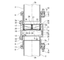
図1に示すように、本発明の通気弁本体1は、排水立て管の上方に延伸された伸頂通気管である配管2、3の途中に設けられ、継手本体4と、通気弁機構5とを有している。なお、本実施形態における「排水立て管」の語は、負圧が伝達される領域として、伸頂通気管を含む概念として用いている。
Embodiments of a vent valve and a vent header system using the vent valve according to the present invention will be described below in detail with reference to the drawings.
As shown in FIG. 1, the vent valve main body 1 of the present invention is provided in the middle of pipes 2 and 3 that are extended vent pipes extending above a drainage stack, and includes a joint main body 4 and a vent valve mechanism 5. And have. In addition, the term “drainage stack” in the present embodiment is used as a concept including an extended top ventilation pipe as a region where negative pressure is transmitted.

継手本体4は、対向する配管2、3の両端部2a、3aに接合する接合部6を両端側に有している。本実施形態においては、この接合部6はフランジ部により構成され、このフランジ部6には貫通孔7が形成されている。一方、配管2、3の外周側にはフランジ部材8、8がそれぞれ装着され、このフランジ部材8には貫通孔7と対応する位置に貫通穴9が形成されている。継手本体4は、フランジ部6の貫通孔9とフランジ部材8の貫通穴9に、例えばT字ボルト等のボルト10をボルト締めして固着されて配管2、3の両端部2a、3aに接合される。このとき、フランジ部6とフランジ部材8との間にはパッキン11が挟着されている。また、継手本体4の略中央付近の側面には開口部12が形成されている。   The joint body 4 has joint portions 6 that are joined to both end portions 2a and 3a of the opposing pipes 2 and 3 on both end sides. In the present embodiment, the joint portion 6 is constituted by a flange portion, and a through hole 7 is formed in the flange portion 6. On the other hand, flange members 8 and 8 are mounted on the outer peripheral sides of the pipes 2 and 3, and through holes 9 are formed in the flange members 8 at positions corresponding to the through holes 7. The joint body 4 is fixed to the through-hole 9 of the flange portion 6 and the through-hole 9 of the flange member 8 by, for example, fastening a bolt 10 such as a T-bolt to the both ends 2a and 3a of the pipes 2 and 3. Is done. At this time, the packing 11 is sandwiched between the flange portion 6 and the flange member 8. An opening 12 is formed on the side surface of the joint body 4 near the center.

通気弁機構5は、弁体15と、環状弁座16と、スプリング17とを有し、これらは筒体18に装着された状態で収容体19に着脱自在に収容されている。
筒体18は、収容体19に形成された後述の収容部20に取付けられる。筒体18の中心位置には、複数の板状のリブ22を介して筒状の弁体保持体23が一体に形成され、この弁体保持体23の中央には連通孔24が形成されている。
The vent valve mechanism 5 includes a valve body 15, an annular valve seat 16, and a spring 17, and these are detachably accommodated in an accommodation body 19 while being attached to a cylindrical body 18.
The cylindrical body 18 is attached to a later-described accommodating portion 20 formed in the accommodating body 19. A cylindrical valve body holding body 23 is integrally formed at a central position of the cylindrical body 18 via a plurality of plate-like ribs 22, and a communication hole 24 is formed at the center of the valve body holding body 23. Yes.

弁体15は、円形状の弁部26と、この弁部26の中央から突出形成された軸部27とを有している。この弁体15は、連通孔24に軸部27が挿着されて筒体18に取付けられ、更に、軸部27の外周側において弁体保持体23と軸部27の先方側に設けられた鍔状の環状輪28との間にスプリング17が弾発付勢した状態で取付けられている。この取付け構造により、通常時には、スプリング17の弾発付勢力により弁体15が環状弁座16の方向に移動してこの環状弁座16に対して着座し、また、負圧が発生した時には弁体15がスプリング17の弾発付勢力に抗して付勢して配管2の管軸2bの方向に可動できるようになっている。   The valve body 15 includes a circular valve portion 26 and a shaft portion 27 that protrudes from the center of the valve portion 26. The valve body 15 is attached to the cylindrical body 18 by inserting a shaft portion 27 into the communication hole 24, and further provided on the front side of the valve body holding body 23 and the shaft portion 27 on the outer peripheral side of the shaft portion 27. The spring 17 is mounted in a state of being elastically biased between the ring-shaped annular ring 28. Due to this mounting structure, the valve body 15 is moved in the direction of the annular valve seat 16 by the elastic urging force of the spring 17 and is seated on the annular valve seat 16 at the normal time. The body 15 is urged against the elastic urging force of the spring 17 so as to be movable in the direction of the tube axis 2 b of the pipe 2.

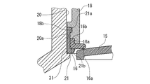
図2に示すように、ゴム等の弾性材料により形成された環状弁座16は、環状の着座部16aが形成され、この着座部16aから略垂直方向に取付部16bが突設形成されている。この環状弁座16は、樹脂等の弾性材料により形成された装着部材21により筒体18に取付けられる。
装着部材21は、図に示すように、断面略L形状を呈し、嵌合凸部21aと係合部21bとを有している。この装着部材21により環状弁座16を取付ける際には、先ず、環状弁座16の取付部16bを筒体18の下部に形成した凹状部18aに装着する。次いで、装着部材21の嵌合凸部21aを筒体18に形成した嵌合凹部18bに嵌合させつつ、係合部21bを着座部16aの下面側に係合させることにより、環状弁座16が筒体18に係止固定される。環状弁座16は、このようにして筒体18の下端側に設けられ、弁体15が可動したときには、この弁体15の外周側付近が環状弁座16の着座部16aに着座できるようになっている。図示しないが、環状弁座と装着部材とは、ゴム製材料によって一体に形成してもよい。
As shown in FIG. 2, the annular valve seat 16 formed of an elastic material such as rubber has an annular seat portion 16a, and a mounting portion 16b projects from the seat portion 16a in a substantially vertical direction. . The annular valve seat 16 is attached to the cylindrical body 18 by a mounting member 21 formed of an elastic material such as resin.
As shown in the drawing, the mounting member 21 has a substantially L-shaped cross section, and has a fitting convex portion 21a and an engaging portion 21b. When attaching the annular valve seat 16 with the attachment member 21, first, the attachment portion 16 b of the annular valve seat 16 is attached to the concave portion 18 a formed in the lower portion of the cylindrical body 18. Next, while engaging the fitting convex portion 21a of the mounting member 21 with the fitting concave portion 18b formed in the cylindrical body 18, the engaging portion 21b is engaged with the lower surface side of the seating portion 16a, whereby the annular valve seat 16 is engaged. Is fixed to the cylindrical body 18. The annular valve seat 16 is thus provided on the lower end side of the cylindrical body 18, and when the valve body 15 is moved, the vicinity of the outer peripheral side of the valve body 15 can be seated on the seating portion 16 a of the annular valve seat 16. It has become. Although not shown, the annular valve seat and the mounting member may be integrally formed of a rubber material.

収容体19は、筒体18を収容可能な収容部20を有し、この収容部20の底付近には装着部材21が係止可能な係止部31が形成されている。また、収容体19には鍔状のキャップ32が形成され、このキャップ32には、固着ボルト33により固着可能に図示しない取付穴が形成されている。また、収容部20の筒体18装着側との反対側にはこの筒体装着側に対して傾斜したテーパ面部34が形成されている。   The accommodating body 19 has an accommodating portion 20 that can accommodate the cylindrical body 18, and a locking portion 31 that can lock the mounting member 21 is formed near the bottom of the accommodating portion 20. Further, a bowl-shaped cap 32 is formed in the container 19, and a mounting hole (not shown) is formed in the cap 32 so as to be fixed by a fixing bolt 33. Further, a tapered surface portion 34 that is inclined with respect to the cylindrical body mounting side is formed on the side opposite to the cylindrical body mounting side of the accommodating portion 20.

収容部20に筒体18(通気弁機構5)を収容すると、装着部材21が係止部31に係止して通気弁機構5が収容部20の所定位置に配置されるようになっている。このとき、図に示すように、装着部材21と収容部20の内周面20aとは密着していなくてもよいが、必要に応じて密着させるようにしてもよい。   When the cylinder 18 (the vent valve mechanism 5) is accommodated in the accommodating part 20, the mounting member 21 is engaged with the engaging part 31, and the vent valve mechanism 5 is arranged at a predetermined position of the accommodating part 20. . At this time, as shown in the drawing, the mounting member 21 and the inner peripheral surface 20a of the accommodating portion 20 do not have to be in close contact, but may be in close contact as necessary.

この場合、収容体19において、収容部20の下方には、図3に示すようにこの収容部20の内径より径の大きい拡径部19aが形成されている。このため、この拡径部19aに、弁開状態の弁部26を収容することにより、図3に示すように、弁部26と拡径部19aとの間を広い通気流路とすることができ、点線矢印に示すように、円滑に通気をおこなうことができる。
なお、通気弁機構5は、環状弁座を筒体の上端に設け、弁部をスプリングにより上方に付勢して弁閉状態とする構造であってもよい。
In this case, in the housing 19, an enlarged diameter portion 19 a having a diameter larger than the inner diameter of the housing portion 20 is formed below the housing portion 20 as shown in FIG. 3. For this reason, by accommodating the valve portion 26 in the valve-opened state in this enlarged diameter portion 19a, as shown in FIG. 3, a wide ventilation channel can be formed between the valve portion 26 and the enlarged diameter portion 19a. It can be ventilated smoothly as shown by the dotted arrows.
The vent valve mechanism 5 may have a structure in which an annular valve seat is provided at the upper end of the cylinder and the valve portion is urged upward by a spring to close the valve.

シール部材36は、環状に形成され、収容体19に通気弁機構5が装着された状態で、この収容体19と筒体18との間に形成された環状溝39に装着される。このシール部材36は、収容体19と継手本体4との間に配設され、収容体19を継手本体4内に装着することによりシール部材36を継手本体4内に密着させて、通気弁機構5の弁機能を発揮するようになっている。   The seal member 36 is formed in an annular shape, and is mounted in an annular groove 39 formed between the container 19 and the cylindrical body 18 in a state where the vent valve mechanism 5 is mounted in the container 19. The seal member 36 is disposed between the container 19 and the joint main body 4, and the seal member 36 is brought into close contact with the joint main body 4 by mounting the container 19 in the joint main body 4. The valve function of 5 is demonstrated.

収容体19は、収容部20に通気弁機構5を収容した状態で開口部12から配管2、3の管軸2b、3b方向と交差する方向に着脱自在に設けられており、継手本体4に装着された状態で、シール用に設けたシール部材36と、ガスケット37とを介して固着ボルト33により継手本体4に固着される。収容体19が継手本体4に装着されたときには、この収容体19にテーパ面部34が設けられていることにより、図1に示すように収容体19と継手本体4との間に空隙38が形成される。なお、収容体19の底面形状は、前記空隙38を形成し得るものであれば、テーパ面部34の他、緩やかな曲面部等を用いてもよい。   The container 19 is detachably provided from the opening 12 in a direction intersecting the tube shafts 2b and 3b directions of the pipes 2 and 3 in a state in which the vent valve mechanism 5 is housed in the container 20. In the mounted state, it is fixed to the joint body 4 by a fixing bolt 33 through a sealing member 36 provided for sealing and a gasket 37. When the container 19 is attached to the joint body 4, a gap 38 is formed between the container 19 and the joint body 4 as shown in FIG. Is done. As long as the bottom surface of the container 19 can form the gap 38, a gently curved surface portion or the like may be used in addition to the tapered surface portion 34.

また、図5に示すように、テーパ面部34とキャップ本体との接続部分には水平底部32aが形成されている。収容体19を開口部12から装着するときには、この水平底部32aが、継手本体4の開口部12における水平縁部12aに乗り上げることにより、収容部20が継手本体4に対して起立し、水平状態となったシール部材36が継手本体内方上面の被シール位置に密着してシール部材36によるシール機能が発揮される。この密着により通気弁機構5が機能する状態となる。
そして、収容体19におけるシール部材36のシール面部位と直交方向に設けられたキャップ32を管軸と平行状態で継手本体4に固定することにより、前記シール機能が維持される。
Further, as shown in FIG. 5, a horizontal bottom portion 32a is formed at a connection portion between the tapered surface portion 34 and the cap body. When the container 19 is mounted from the opening 12, the horizontal bottom 32 a rides on the horizontal edge 12 a in the opening 12 of the joint body 4, so that the container 20 stands up with respect to the joint body 4 and is in a horizontal state. Thus, the sealing member 36 comes into close contact with the position to be sealed on the inner upper surface of the joint body, and the sealing function of the sealing member 36 is exhibited. This close contact makes the vent valve mechanism 5 function.
And the said sealing function is maintained by fixing to the coupling main body 4 the cap 32 provided in the orthogonal direction with the sealing surface site | part of the sealing member 36 in the container 19 in a state parallel to a pipe axis.

なお、上記構造の他にも、予め継手本体4の内方下面の奥部に突起4bを設けておき、この突起部4bにテーパ面部34が一体に乗り上げることで、収容体19を継手本体4に対して起立するようにしてもよい。また、通気弁機構5を収容した収容体19の重心をキャップ32側に設定することにより、収容部20の起立を容易に行なうようにしたり、重心を継手本体4への挿入側に設定することにより、後述する収容部20の傾倒を容易に行なうようにしてもよい。   In addition to the above structure, a protrusion 4b is provided in the inner bottom surface of the joint main body 4 in advance, and the container 19 is attached to the joint main body 4 by the taper surface portion 34 riding on the protrusion 4b. You may make it stand up with respect to. In addition, by setting the center of gravity of the container 19 that houses the vent valve mechanism 5 to the cap 32 side, the container 20 can be easily raised, or the center of gravity is set to the insertion side of the joint body 4. Accordingly, the accommodating portion 20 described later may be easily tilted.

ここで、通気弁機構5を継手本体4から取外す場合を述べる。この場合、図4に示すように、固着ボルト33を緩めた状態で、収容体19を通気弁機構5の収容側と反対側の空隙38側に傾倒させる。この収容体19の傾倒により、シール部材36が継手本体4の被シール位置から離間する。続いて、図5に示すように、この状態を保持しながら収容体19を管軸2b、3b方向と交差する方向に引き出すことにより、シール部材36が継手本体4に対して摺動することがなく、このシール部材36が摩耗したり傷付いたりすることが防がれる。   Here, the case where the ventilation valve mechanism 5 is removed from the joint body 4 will be described. In this case, as shown in FIG. 4, with the fixing bolt 33 loosened, the containing body 19 is tilted to the side of the gap 38 opposite to the containing side of the vent valve mechanism 5. Due to the inclination of the container 19, the seal member 36 is separated from the sealed position of the joint body 4. Subsequently, as shown in FIG. 5, the seal member 36 can slide with respect to the joint body 4 by pulling out the container 19 in the direction intersecting the tube shafts 2 b and 3 b while maintaining this state. This prevents the seal member 36 from being worn or damaged.

更に、図6に示すように、通気弁機構5を収容体19から管軸2b、3b方向に抜き出すことでこの収容体19から容易に分離させることができ、この通気弁機構5に対して必要に応じて弁体15や環状弁座16等を交換したり、これらに清掃を施して付着した異物等を除去できる。   Further, as shown in FIG. 6, the ventilation valve mechanism 5 can be easily separated from the housing body 19 by being pulled out from the housing body 19 in the direction of the tube shafts 2 b and 3 b. Accordingly, it is possible to replace the valve body 15 and the annular valve seat 16 or the like, or to remove the adhered foreign matter or the like by cleaning them.

次に、上記実施形態における通気弁本体の動作について説明する。
下方側の配管2の下方に延設された排水立て管内に排水が流れ、この配管2内に負圧が生じると、図3に示すように、それまで環状弁座16に着座していた弁体15がスプリング17の弾発付勢力に抗して下方側に移動して通気弁機構5が弁開状態になり、上方側の配管3側から下方側の配管2に空気(大気)が流入する。このように、負圧が発生すると、この負圧と大気圧との圧力差に応じて通気弁機構5が動作することで空気が流入して負圧が軽減される。
Next, the operation of the vent valve body in the above embodiment will be described.
When drainage flows into a drainage stack extending below the lower pipe 2 and negative pressure is generated in the pipe 2, as shown in FIG. 3, the valve previously seated on the annular valve seat 16 is used. The body 15 moves downward against the elastic urging force of the spring 17 so that the vent valve mechanism 5 is opened, and air (atmosphere) flows into the lower pipe 2 from the upper pipe 3 side. To do. As described above, when negative pressure is generated, the vent valve mechanism 5 operates according to the pressure difference between the negative pressure and the atmospheric pressure, so that air flows in and the negative pressure is reduced.

続いて、上記の弁開動作によって下方側の配管2と上方側の配管3内の圧力差が小さくなると、弁体15がスプリング17の弾発付勢力によって弁閉方向に移動して環状弁座16に着座する。この動作により通気弁機構5が弁閉状態になり、下方側の配管2内の臭気が上方側の配管3側に漏れることが防がれる。また、このとき、シール部材36によって収容体19と継手本体4との間から臭気が漏れることも防がれている。   Subsequently, when the pressure difference between the lower pipe 2 and the upper pipe 3 is reduced by the above valve opening operation, the valve body 15 is moved in the valve closing direction by the elastic biasing force of the spring 17, and the annular valve seat is moved. Sitting at 16. By this operation, the vent valve mechanism 5 is closed, and the odor in the lower pipe 2 is prevented from leaking to the upper pipe 3 side. At this time, the sealing member 36 prevents odor from leaking from between the container 19 and the joint body 4.

図7においては、本発明の通気弁の他の実施形態を示している。なお、この実施形態以降の実施形態において、上記実施形態と同一部分は同一符号によってあらわし、その説明を省略する。
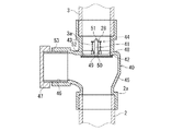
この実施形態における通気弁本体40は、弁体41と環状弁座42とスプリング43とを有する通気弁機構44が継手本体45の内部に直接装着され、更に、継手本体45に形成された開口部46にキャップ部材47が着脱自在に取付けられることにより、この開口部46が被蓋されている。これにより、この通気弁本体40は、収容体や筒体が省略された構造になっている。
FIG. 7 shows another embodiment of the vent valve of the present invention. In addition, in embodiment after this embodiment, the same part as the said embodiment is represented by the same code | symbol, and the description is abbreviate | omitted.
In the vent valve body 40 in this embodiment, a vent valve mechanism 44 having a valve body 41, an annular valve seat 42 and a spring 43 is directly mounted inside the joint body 45, and an opening formed in the joint body 45 is further provided. A cap member 47 is detachably attached to 46 so that the opening 46 is covered. Thereby, this vent valve main body 40 has a structure in which a container and a cylinder are omitted.

弁体41は、継手本体45内にリブ48を介して形成された弁体保持体49の連通孔50に軸部51が挿着されることにより取付けられる。この弁体41における環状弁座42側にはパッキン部材52が設けられている。また、環状弁座42は、継手本体45内に一体に形成されている。このような通気弁機構44により、通気弁本体40は、弁体41が環状弁座42に着座したときに、パッキン部材52がこの環状弁座42に当接する構造になっている。なお、弁体保持部49は、ねじ込みや嵌合などにより、継手本体45に着脱自在に固定されている。   The valve body 41 is attached by inserting the shaft portion 51 into the communication hole 50 of the valve body holding body 49 formed in the joint body 45 through the rib 48. A packing member 52 is provided on the valve body 41 on the annular valve seat 42 side. Further, the annular valve seat 42 is integrally formed in the joint main body 45. With such a vent valve mechanism 44, the vent valve main body 40 has a structure in which the packing member 52 contacts the annular valve seat 42 when the valve body 41 is seated on the annular valve seat 42. In addition, the valve body holding part 49 is detachably fixed to the joint body 45 by screwing or fitting.

キャップ部材47は、開口部46に嵌合可能な嵌合突部53を有し、この嵌合突部52を介して継手本体45に取付けられる。キャップ部材47を取外し、開口部46から手を入れることで通気弁機構44を簡単に取外しできる。この場合、弁体41を継手本体45から取外したときにパッキン部材52も同時に取外されるため、このパッキン部材52を容易に交換することが可能になっている。   The cap member 47 has a fitting protrusion 53 that can be fitted into the opening 46, and is attached to the joint body 45 via the fitting protrusion 52. The vent valve mechanism 44 can be easily removed by removing the cap member 47 and putting a hand through the opening 46. In this case, since the packing member 52 is also removed at the same time when the valve body 41 is removed from the joint main body 45, the packing member 52 can be easily replaced.

この通気弁本体40は、図8において、前記実施形態と同様に弁体41がスプリング43の弾発付勢力に抗して下方側に移動することにより弁開状態になって、上方側の配管3側から下方側の配管2に空気が流入して負圧が軽減される。このように、通気弁機構44は必ずしも通気弁本体40と別体に設ける必要はなく、上述したように通気弁本体40から蓋状のキャップ部材47を取外すことにより開口部46を開口する構造に設けるようにしてもよい。   In FIG. 8, the vent valve main body 40 is opened as the valve element 41 moves downward against the elastic biasing force of the spring 43 in the same manner as in the above-described embodiment. Air flows into the lower piping 2 from the 3 side, and the negative pressure is reduced. As described above, the vent valve mechanism 44 is not necessarily provided separately from the vent valve main body 40, and has a structure in which the opening 46 is opened by removing the lid-like cap member 47 from the vent valve main body 40 as described above. You may make it provide.

また、図9においては、本発明の通気弁を他の構造の通気弁に応用した例を示している。この通気弁本体60は、継手本体61の片側のみに接合部62が形成され、この接合部62を配管2の端部2a側に接合するようにしたものである。この場合、継手本体61の上端側に開口部63が形成され、この開口部63に対して通気弁機構5を装着した筒体18を嵌合固着できるようになっている。この通気弁機構5の取付け構造は、前述した実施形態における収容体19に対する筒体18の収容構造と同様であるため、その説明を省略する。   FIG. 9 shows an example in which the vent valve of the present invention is applied to a vent valve having another structure. The vent valve main body 60 has a joint portion 62 formed only on one side of the joint main body 61, and the joint portion 62 is joined to the end 2 a side of the pipe 2. In this case, an opening 63 is formed on the upper end side of the joint body 61, and the cylindrical body 18 equipped with the vent valve mechanism 5 can be fitted and fixed to the opening 63. Since the attachment structure of the vent valve mechanism 5 is the same as the housing structure of the cylindrical body 18 with respect to the housing body 19 in the above-described embodiment, the description thereof is omitted.

継手本体61の上部には、ステンレス等により形成された通気可能な逆椀状の取付部材65が取付けられ、更に、この上からカバー部材66が被せられている。カバー部材66は、通気路67を有し、この通気路67を介して空気が通気弁機構5側に流入できるようになっている。このカバー部材66により、通気路67を確保しながら通気弁機構5と継手本体61内部とが覆われて異物の浸入が防がれている。   On the upper part of the joint main body 61, an airtight inverted saddle-shaped attachment member 65 formed of stainless steel or the like is attached, and a cover member 66 is covered from above. The cover member 66 has a ventilation path 67, and air can flow into the ventilation valve mechanism 5 through the ventilation path 67. The cover member 66 covers the ventilation valve mechanism 5 and the inside of the joint main body 61 while securing the ventilation path 67 to prevent foreign matter from entering.

取付部材65とカバー部材66とは、ともにネジ68により継手本体61に着脱自在に取付けられる。この取付け構造により、ネジ68を緩めることによりカバー部材66と取付部材65とを継手本体61から容易に取外しでき、更に、通気弁機構5を継手本体61から取外すことにより、点検や部品の交換等を簡単におこなうことができる。   Both the attachment member 65 and the cover member 66 are detachably attached to the joint body 61 with screws 68. With this mounting structure, the cover member 66 and the mounting member 65 can be easily removed from the joint body 61 by loosening the screws 68, and further, the inspection and replacement of parts can be performed by removing the vent valve mechanism 5 from the joint body 61. Can be done easily.

次に、上述した通気弁を用いた通気ヘッダシステムの実施形態とその作用を述べる。
図10においては、本発明の通気弁を用いた通気ヘッダシステムの一実施形態を示している。ヘッダシステム本体70は、例えば、マンション等の複数階からなる図示しない建築物内の排水流路として設けられ、複数の排水立て管71A、71B、71Cとからなる排水立て管71、通気ヘッダ72、ベントキャップ73、排水横主管74、排水横枝管75を有している。
Next, an embodiment of the ventilation header system using the above-described ventilation valve and its operation will be described.
In FIG. 10, one Embodiment of the ventilation header system using the ventilation valve of this invention is shown. The header system body 70 is provided, for example, as a drainage channel in a building (not shown) composed of a plurality of floors such as an apartment, and includes a drainage stack 71 including a plurality of drainage stacks 71A, 71B, 71C, a ventilation header 72, A vent cap 73, a horizontal drain main pipe 74, and a horizontal drain branch pipe 75 are provided.

各排水立て管71は、上方に伸頂通気管76が延設されて排水時に内部が通気されるようになっており、更に、この伸頂通気管76の上部側に通気ヘッダ72が接続されている。通気ヘッダ72は、排水立て管71と連通してこの排水立て管71内部を通気するようになっており、この通気ヘッダ72を設けることによって排水立て管71の通気側が1箇所に集約されている。更に、通気ヘッダ72の上部にベントキャップ73が設けられ、このベントキャップ73の側面又は底面には、図示しない開口部が設けられている。この開口部から空気が入ると、この空気は、通気ヘッダ72を介して排水立て管71内に流入する。また、このベントキャップ73により、通気弁本体1までの間が一方向の通気流路となり、通気弁本体1から臭気がこのベントキャップ73側に漏れることが極めて少ない。こにより、伸頂通気管76の設置場所の制約も緩和される。また、ベントキャップ73により、雨水やゴミ、害虫などの異物が通気弁機構5に浸入することが防がれる。   Each drainage stack 71 has an extending vent pipe 76 extending upward so that the inside is vented during drainage, and a vent header 72 is connected to the upper side of the extending vent pipe 76. ing. The ventilation header 72 communicates with the drainage stack 71 to ventilate the interior of the drainage stack 71. By providing the ventilation header 72, the ventilation side of the drainage stack 71 is concentrated at one place. . Further, a vent cap 73 is provided on the upper portion of the ventilation header 72, and an opening (not shown) is provided on a side surface or a bottom surface of the vent cap 73. When air enters from this opening, the air flows into the drainage stack 71 through the ventilation header 72. In addition, the vent cap 73 provides a one-way ventilation channel between the vent valve body 1 and odors from the vent valve body 1 rarely leak to the vent cap 73 side. Thereby, the restrictions on the installation location of the extended vent pipe 76 are also eased. Further, the vent cap 73 prevents foreign matter such as rainwater, dust, and insects from entering the vent valve mechanism 5.

排水横主管74は、ヘッダシステム本体70の下方側に排水立て管71と連通するように接続されている。また、排水横枝管75は、排水立て管71に対して建築物の各フロアごとに接続され、この排水横枝管75には図示しない排水器具が接続されている。この構造により、ヘッダシステム本体70の排水器具から排水されると、この排水は、排水横枝管75を介して排水立て管71に流入し、続いて、排水横主管74から外部に流れるようになっている。   The drainage horizontal main pipe 74 is connected to the lower side of the header system main body 70 so as to communicate with the drainage stack 71. The drainage horizontal branch pipe 75 is connected to the drainage stack 71 for each floor of the building, and a drainage device (not shown) is connected to the drainage horizontal branch pipe 75. With this structure, when drained from the drainage device of the header system main body 70, the drainage flows into the drainage stack 71 through the drainage horizontal branch pipe 75, and then flows from the drainage horizontal main pipe 74 to the outside. It has become.

上記のヘッダシステム本体において、通気弁本体1は、各排水立て管71の各上部77と通気ヘッダ72との間、又は、排水立て管71の上方に延設された伸頂通気管76の途中位置に設けられるが、本実施形態においては、通気弁本体1を排水立て管71と通気ヘッダ72との間に設ける場合を述べる。通気弁本体1は、排水立て管71と通気ヘッダ72の各端部71a、72aに継手本体4の接合部6、6がそれぞれ接合され、通気弁機構5は、継手本体4の接合状態を維持した状態でそれぞれの継手本体4に対して着脱自在に設けられている。   In the header system main body, the vent valve main body 1 is provided between the upper portions 77 of the drainage stacks 71 and the ventilation header 72 or in the middle of the extended top venting pipe 76 extending above the drainage stack 71. In this embodiment, the case where the ventilation valve main body 1 is provided between the drainage stack 71 and the ventilation header 72 will be described. In the vent valve body 1, the joint portions 6 and 6 of the joint body 4 are joined to the end portions 71 a and 72 a of the drainage stack 71 and the vent header 72, respectively, and the vent valve mechanism 5 maintains the joint state of the joint body 4. In this state, each joint body 4 is detachably provided.

また、接合部6は、前述したようにフランジ部により形成され、このフランジ部6と配管である排水立て管71と通気ヘッダ72との外周側に装着された前記フランジ部材8とをボルト10締めにより固着して、継手本体4によって排水立て管71と通気ヘッダ72とが接合される。   Further, the joint portion 6 is formed by the flange portion as described above, and the flange portion 6 and the flange member 8 attached to the outer peripheral side of the drainage stack 71 and the ventilation header 72 are tightened with bolts 10. The drainage stack 71 and the ventilation header 72 are joined by the joint body 4.

このヘッダシステム本体70は、通気弁本体1における通気弁機構5の前述した動作により、通常の排水がない場合には弁閉状態を維持し、システム内の臭気が通気ヘッダ72やベントキャップ73側に漏出することが防止されている。
また、配管内に負圧が生じた際には、負圧が生じた排水立て管71に取付けられた通気弁本体1が弁開動作して当該排水立て管71内の負圧が軽減される。
The header system main body 70 maintains the valve closed state when there is no normal drainage by the above-described operation of the vent valve mechanism 5 in the vent valve main body 1, and the odor in the system is on the side of the vent header 72 or the vent cap 73. To prevent leakage.
In addition, when negative pressure is generated in the pipe, the vent valve body 1 attached to the drainage stack 71 where the negative pressure is generated opens and the negative pressure in the drainage stack 71 is reduced. .

この場合、通気弁本体1がそれぞれの排水立て管71に対して個別に設けられているため、負圧が生じた排水立て管71以外の排水立て管71の通気弁本体1は弁閉状態を維持し、これらの排水立て管内71に下方から上方への通気時とは反対向きの空気の流れを生じることが防がれる。このように、このヘッダシステム本体70は、負圧が生じる排水立て管71のみの通気弁機構5が動作して負圧が軽減されるため、排水立て管71内に負圧発生時に生じる空気の流れ方向以外の向きの流れが生じることがなく、通気弁本体1に排水側から下水管内の害虫などの異物が上昇し流れ込んで付着したりすることが防がれ、常時通気機能と臭気漏れ機構とが維持される。   In this case, since the vent valve body 1 is individually provided for each drainage stack 71, the vent valve body 1 of the drainage stack 71 other than the drainage stack 71 where the negative pressure is generated is in a valve-closed state. Thus, it is possible to prevent the flow of air in the direction opposite to the air flow from the lower side to the upper side in these drainage stacks 71. As described above, the header system main body 70 operates the vent valve mechanism 5 of only the drainage stack 71 where negative pressure is generated to reduce the negative pressure. There is no flow in any direction other than the flow direction, and foreign matter such as pests in the sewage pipe is prevented from rising and flowing from the drainage side to the ventilation valve body 1 to prevent it from adhering. And is maintained.

また、この負圧を軽減する動作により、排水器具に設けられている図示しないトラップの封水が減少することが抑えられ、ヘッダシステム本体70内の下水ガスが屋内に浸入することも防止されて衛生性が保たれる。   In addition, the operation of reducing the negative pressure suppresses a decrease in the sealing water of a trap (not shown) provided in the drainage device, and prevents the sewage gas in the header system body 70 from entering the room. Hygiene is maintained.

なお、本発明の通気弁は、通気ヘッダシステム70以外の配管に対してもその配管の途中に配設可能な通気弁として使用でき、この場合にも通気ヘッダシステム70の場合と同様に接合して同様の機能を発揮することができる。
また、図示しないが、本発明の通気弁をヘッダシステム本体70に接続し、継手本体内の通気弁機構を取外して試験用治具を内蔵することにより、配管施工時の満水試験をすることも可能である。
The vent valve of the present invention can be used as a vent valve that can be disposed in the middle of a pipe other than the vent header system 70. In this case, the vent valve is joined in the same manner as the vent header system 70. The same function.
In addition, although not shown in the drawings, a water filling test at the time of piping construction may be performed by connecting the vent valve of the present invention to the header system main body 70, removing the vent valve mechanism in the joint main body, and incorporating a test jig. Is possible.

本発明における通気弁の一実施形態を示した断面図である。It is sectional drawing which showed one Embodiment of the vent valve in this invention. 図1の通気弁の環状弁座付近を示した拡大図である。It is the enlarged view which showed the annular valve seat vicinity of the ventilation valve of FIG. 図1の通気弁が弁開した状態を示した断面図である。FIG. 2 is a cross-sectional view showing a state where the vent valve of FIG. 1 is opened. 図1の通気弁の収容部を傾倒させた状態を示した断面図である。It is sectional drawing which showed the state which inclined the accommodating part of the ventilation valve of FIG. 図1の通気弁から収容部を抜き出した状態を示した断面図である。It is sectional drawing which showed the state which extracted the accommodating part from the ventilation valve of FIG. 通気弁機構を収容部から分離した状態を示した分離斜視図である。It is the isolation | separation perspective view which showed the state which isolate | separated the ventilation valve mechanism from the accommodating part. 本発明の通気弁の他の実施形態を示した断面図である。It is sectional drawing which showed other embodiment of the ventilation valve of this invention. 図6の通気弁が弁開した状態を示した断面図である。FIG. 7 is a cross-sectional view showing a state where the vent valve of FIG. 6 is opened. 通気弁の他例を示した断面図である。It is sectional drawing which showed the other example of the ventilation valve. 通気弁を用いた通気ヘッダシステムの一実施形態を示した模式図である。It is the schematic diagram which showed one Embodiment of the ventilation header system using a ventilation valve. 従来の通気ヘッダシステムを示した模式図である。It is the schematic diagram which showed the conventional ventilation header system.

符号の説明Explanation of symbols

1 通気弁本体
2、3 配管
2a、3a 端部
4 継手本体
5 通気弁機構
6 フランジ部(接合部)
8 フランジ部材
10 ボルト
12 開口部
15 弁体
16 環状弁座
17 スプリング
19 収容体
32 キャップ
36 シール部材
70 ヘッダシステム本体
71 排水立て管
72 通気ヘッダ
77 上部
DESCRIPTION OF SYMBOLS 1 Ventilation valve main body 2, 3 Piping 2a, 3a End part 4 Joint main body 5 Ventilation valve mechanism 6 Flange part (joint part)
8 Flange member 10 Bolt 12 Opening 15 Valve body 16 Annular valve seat 17 Spring 19 Housing 32 Cap 36 Seal member 70 Header system body 71 Drainage stack 72 Ventilation header 77 Upper part

Claims (7)

対向する配管の両端部に接合する接合部を有する継手本体の側面に開口部を設け、この開口部に対して通気弁機構を前記配管の管軸方向と交差する方向から着脱自在に設けたことを特徴とする通気弁。   An opening is provided in the side surface of the joint body having a joint portion that joins both ends of the opposing pipe, and a vent valve mechanism is provided to the opening from the direction crossing the pipe axis direction of the pipe. Ventilation valve characterized by. 前記通気弁機構をキャップを有する収容体に着脱自在に収容し、この収容体を前記継手本体の開口部から前記配管の管軸方向と交差する方向に装着した請求項1に記載の通気弁。   The vent valve according to claim 1, wherein the vent valve mechanism is detachably accommodated in an accommodating body having a cap, and the accommodating body is mounted in a direction intersecting with a pipe axis direction of the pipe from an opening of the joint body. 前記通気弁機構は、前記管軸方向に可動する弁体と、この弁体の外周付近が着座する環状弁座と、前記弁体を前記環状弁座の方向に弾発付勢するスプリングとを有する請求項2に記載の通気弁。   The vent valve mechanism includes a valve body movable in the tube axis direction, an annular valve seat on which the vicinity of the outer periphery of the valve body is seated, and a spring that elastically biases the valve body in the direction of the annular valve seat. The vent valve according to claim 2. 前記収容体と継手本体との間にシール部材を設け、前記収容体を前記継手本体内に装着することにより、前記シール部材を前記継手本体内に密着させて前記通気弁機構の弁機能を発揮するようにした請求項2又は3に記載の通気弁。   A seal member is provided between the container and the joint body, and the container is mounted in the joint body, thereby bringing the seal member into close contact with the joint body and exerting the valve function of the vent valve mechanism. The vent valve according to claim 2 or 3, wherein: 複数の排水立て管と、この排水立て管の上部に設けられて前記排水立て管内を連通させて通気するようにした通気ヘッダとを有する通気ヘッダシステムであって、前記排水立て配管の各上部と前記通気ヘッダとの間に請求項1乃至4の何れか1項に記載の通気弁を設けたことを特徴とする通気弁を用いた通気ヘッダシステム。   A ventilation header system having a plurality of drainage stacks and a ventilation header provided at an upper part of the drainage stacks and communicating with the interior of the drainage stacks, each upper part of the drainage stacks, A ventilation header system using a ventilation valve, wherein the ventilation valve according to any one of claims 1 to 4 is provided between the ventilation header. 前記排水立て管と通気ヘッダとの間、又は、前記排水立て管の途中位置に前記継手本体の接合部を接合し、この継手本体の接合状態を維持した状態で前記通気弁機構をこの継手本体からそれぞれ着脱自在に設けた請求項5に記載の通気弁を用いた通気ヘッダシステム。   The joint portion of the joint body is joined between the drainage stack and the ventilation header or in the middle of the drainage stack, and the joint body of the joint is maintained in a state where the joint state of the joint body is maintained. The ventilation header system using the ventilation valve according to claim 5 provided detachably from each other. 前記継手本体の接合部をフランジ部とし、このフランジ部と、前記排水立て管と通気ヘッダとの外周側にそれぞれ装着したフランジ部材とをボルト締めにより固着して前記継手本体により前記排水立て管と通気ヘッダとを接合した請求項5又は6に記載の通気弁を用いた通気ヘッダシステム。   The joint part of the joint body is a flange part, and the flange part and flange members mounted on the outer peripheral sides of the drainage standpipe and the ventilation header are fixed by bolting, and the drainage standpipe is connected to the drainage standpipe by the joint body. The ventilation header system using the ventilation valve of Claim 5 or 6 joined with the ventilation header.
JP2008183518A 2008-07-15 2008-07-15 Ventilation valve device and ventilation header system using the same Active JP5473268B2 (en)

Priority Applications (1)

Application Number Priority Date Filing Date Title
JP2008183518A JP5473268B2 (en) 2008-07-15 2008-07-15 Ventilation valve device and ventilation header system using the same

Applications Claiming Priority (1)

Application Number Priority Date Filing Date Title
JP2008183518A JP5473268B2 (en) 2008-07-15 2008-07-15 Ventilation valve device and ventilation header system using the same

Publications (2)

Publication Number Publication Date
JP2010024618A true JP2010024618A (en) 2010-02-04
JP5473268B2 JP5473268B2 (en) 2014-04-16

Family

ID=41730699

Family Applications (1)

Application Number Title Priority Date Filing Date
JP2008183518A Active JP5473268B2 (en) 2008-07-15 2008-07-15 Ventilation valve device and ventilation header system using the same

Country Status (1)

Country Link
JP (1) JP5473268B2 (en)

Cited By (5)

* Cited by examiner, † Cited by third party
Publication number Priority date Publication date Assignee Title
JP2017082553A (en) * 2015-10-30 2017-05-18 株式会社キッツ Ventilation-integrated joint
KR101757418B1 (en) * 2015-08-25 2017-07-12 주식회사 디아 Apparatus for preventing smell from flowing backward of drainage
JP2019211225A (en) * 2018-05-31 2019-12-12 丸一株式会社 Joint member
JP2020056619A (en) * 2018-09-28 2020-04-09 丸一株式会社 Joint member for inspection and leakage inspection method for piping using the same
JP2020172963A (en) * 2019-04-09 2020-10-22 アロン化成株式会社 Ventilation valve

Citations (4)

* Cited by examiner, † Cited by third party
Publication number Priority date Publication date Assignee Title
JP2000080692A (en) * 1998-09-07 2000-03-21 Taisei Corp Coupling jig for testing water-full piping system
JP2003064745A (en) * 2001-05-28 2003-03-05 Kitz Corp Venting device for drainage
JP2004124356A (en) * 2001-09-06 2004-04-22 Morinaga Eng Kk Drain pipe system and ventilation valve device for drainage
JP2008013986A (en) * 2006-07-05 2008-01-24 Hitachi Metals Ltd Drain pipe joint and cartridge member

Patent Citations (4)

* Cited by examiner, † Cited by third party
Publication number Priority date Publication date Assignee Title
JP2000080692A (en) * 1998-09-07 2000-03-21 Taisei Corp Coupling jig for testing water-full piping system
JP2003064745A (en) * 2001-05-28 2003-03-05 Kitz Corp Venting device for drainage
JP2004124356A (en) * 2001-09-06 2004-04-22 Morinaga Eng Kk Drain pipe system and ventilation valve device for drainage
JP2008013986A (en) * 2006-07-05 2008-01-24 Hitachi Metals Ltd Drain pipe joint and cartridge member

Cited By (8)

* Cited by examiner, † Cited by third party
Publication number Priority date Publication date Assignee Title
KR101757418B1 (en) * 2015-08-25 2017-07-12 주식회사 디아 Apparatus for preventing smell from flowing backward of drainage
JP2017082553A (en) * 2015-10-30 2017-05-18 株式会社キッツ Ventilation-integrated joint
JP2019211225A (en) * 2018-05-31 2019-12-12 丸一株式会社 Joint member
JP7115736B2 (en) 2018-05-31 2022-08-09 丸一株式会社 Joint member
JP2020056619A (en) * 2018-09-28 2020-04-09 丸一株式会社 Joint member for inspection and leakage inspection method for piping using the same
JP7215799B2 (en) 2018-09-28 2023-01-31 丸一株式会社 A joint member for inspection and a leak test method for piping using the joint member for inspection.
JP2020172963A (en) * 2019-04-09 2020-10-22 アロン化成株式会社 Ventilation valve
JP7212574B2 (en) 2019-04-09 2023-01-25 アロン化成株式会社 vent valve

Also Published As

Publication number Publication date
JP5473268B2 (en) 2014-04-16

Similar Documents

Publication Publication Date Title
US11466438B2 (en) Automatic draining back flow prevention device
USRE35532E (en) Air Admittance valve for resisting high internal pressure
US7886765B2 (en) Living-hinge air vent valve
JP5473268B2 (en) Ventilation valve device and ventilation header system using the same
JP4252553B2 (en) Drainage equipment in the building
JP5295677B2 (en) Ventilation device
JP3681688B2 (en) Drainage pipe fitting device
JP3611829B2 (en) Drainage vent
JP2009174145A (en) Ventilating device for converging gully
JP4762624B2 (en) Positive pressure buffer and its drainage system
JP5706659B2 (en) Cleaning port lid in drainage pipeline
JP4304369B2 (en) Floor drain trap with ventilation function
JP4907640B2 (en) Drainage pipe fitting device
JP4184416B2 (en) Drainage vent
JP5201970B2 (en)
JP5269397B2 (en) Drainage
JP2001262655A (en) Ventilation apparatus for drainage
JP2014119111A (en) Lower vent valve for drainage
JP4163743B1 (en) Ventilator with built-in vent lid
JP2010116744A (en) Intake valve for drainage pipe
JP2019017898A (en) Pipe joint for temporary toilet
JPH10141533A (en) Intake valve
JP4131872B2 (en) Drainage vent
JP4056994B2 (en) Drainage vent
JP5133764B2 (en) Ventilator with built-in vent lid

Legal Events

Date Code Title Description
A621 Written request for application examination

Free format text: JAPANESE INTERMEDIATE CODE: A621

Effective date: 20110714

A977 Report on retrieval

Free format text: JAPANESE INTERMEDIATE CODE: A971007

Effective date: 20130104

A131 Notification of reasons for refusal

Free format text: JAPANESE INTERMEDIATE CODE: A131

Effective date: 20130514

A521 Request for written amendment filed

Free format text: JAPANESE INTERMEDIATE CODE: A523

Effective date: 20130716

TRDD Decision of grant or rejection written
A01 Written decision to grant a patent or to grant a registration (utility model)

Free format text: JAPANESE INTERMEDIATE CODE: A01

Effective date: 20140107

A61 First payment of annual fees (during grant procedure)

Free format text: JAPANESE INTERMEDIATE CODE: A61

Effective date: 20140204

R150 Certificate of patent or registration of utility model

Ref document number: 5473268

Country of ref document: JP

Free format text: JAPANESE INTERMEDIATE CODE: R150

Free format text: JAPANESE INTERMEDIATE CODE: R150

R250 Receipt of annual fees

Free format text: JAPANESE INTERMEDIATE CODE: R250

R250 Receipt of annual fees

Free format text: JAPANESE INTERMEDIATE CODE: R250

R250 Receipt of annual fees

Free format text: JAPANESE INTERMEDIATE CODE: R250

R250 Receipt of annual fees

Free format text: JAPANESE INTERMEDIATE CODE: R250

R250 Receipt of annual fees

Free format text: JAPANESE INTERMEDIATE CODE: R250

R250 Receipt of annual fees

Free format text: JAPANESE INTERMEDIATE CODE: R250

R250 Receipt of annual fees

Free format text: JAPANESE INTERMEDIATE CODE: R250

S531 Written request for registration of change of domicile

Free format text: JAPANESE INTERMEDIATE CODE: R313531

R350 Written notification of registration of transfer

Free format text: JAPANESE INTERMEDIATE CODE: R350

R250 Receipt of annual fees

Free format text: JAPANESE INTERMEDIATE CODE: R250