JP2010023806A - Actuator for controlling vehicle drive - Google Patents
Actuator for controlling vehicle drive Download PDFInfo
- Publication number
- JP2010023806A JP2010023806A JP2008191167A JP2008191167A JP2010023806A JP 2010023806 A JP2010023806 A JP 2010023806A JP 2008191167 A JP2008191167 A JP 2008191167A JP 2008191167 A JP2008191167 A JP 2008191167A JP 2010023806 A JP2010023806 A JP 2010023806A
- Authority
- JP
- Japan
- Prior art keywords
- gear
- vehicle drive
- drive control
- power
- counter gear
- Prior art date
- Legal status (The legal status is an assumption and is not a legal conclusion. Google has not performed a legal analysis and makes no representation as to the accuracy of the status listed.)
- Granted
Links
Images


Classifications
-
- Y—GENERAL TAGGING OF NEW TECHNOLOGICAL DEVELOPMENTS; GENERAL TAGGING OF CROSS-SECTIONAL TECHNOLOGIES SPANNING OVER SEVERAL SECTIONS OF THE IPC; TECHNICAL SUBJECTS COVERED BY FORMER USPC CROSS-REFERENCE ART COLLECTIONS [XRACs] AND DIGESTS
- Y02—TECHNOLOGIES OR APPLICATIONS FOR MITIGATION OR ADAPTATION AGAINST CLIMATE CHANGE
- Y02T—CLIMATE CHANGE MITIGATION TECHNOLOGIES RELATED TO TRANSPORTATION
- Y02T10/00—Road transport of goods or passengers
- Y02T10/60—Other road transportation technologies with climate change mitigation effect
- Y02T10/62—Hybrid vehicles
-
- Y—GENERAL TAGGING OF NEW TECHNOLOGICAL DEVELOPMENTS; GENERAL TAGGING OF CROSS-SECTIONAL TECHNOLOGIES SPANNING OVER SEVERAL SECTIONS OF THE IPC; TECHNICAL SUBJECTS COVERED BY FORMER USPC CROSS-REFERENCE ART COLLECTIONS [XRACs] AND DIGESTS
- Y02—TECHNOLOGIES OR APPLICATIONS FOR MITIGATION OR ADAPTATION AGAINST CLIMATE CHANGE
- Y02T—CLIMATE CHANGE MITIGATION TECHNOLOGIES RELATED TO TRANSPORTATION
- Y02T10/00—Road transport of goods or passengers
- Y02T10/60—Other road transportation technologies with climate change mitigation effect
- Y02T10/72—Electric energy management in electromobility
Abstract
Description
本発明は、電動モータによって車輪を回転駆動するインホイール式の車両駆動制御用アクチュエータに関する。 The present invention relates to an in-wheel type vehicle drive control actuator that rotationally drives wheels by an electric motor.
従来、インホイール式の駆動機構を有する制動機構として、油圧式の制動機構を使用した特開2007−223381号広報(特許文献1)が公知であり、ポンプ系(モータ、ポンプ、アキュムレータ等)から成るブレーキオイルの圧力源をホイール外に配置することなく効率的にホイール内に配置することによって、インホイール式モータのスペース効率化を行っている。また、特開平11−157422号広報(特許文献2)に開示された車両用制動装置では、車輪毎に制動エネルギー回生ユニットを設けた油圧式の制動機構が記載されており、車両減速時の運動エネルギーを有効に利用するための提案が成されている。
しかしながら、特許文献1に記載された制動機構では、ホイール内にブレーキオイルの圧力源が効率的に配置されるという利点はあるものの、油圧駆動であるためにオイルポンプやバルブ等の多数の構成部品を必要とするため、重量が増加したり、制御が複雑化するという課題が残り、低コスト化や小型化、軽量化の観点からは改善の余地がある。また、特許文献2に記載された車両用制動装置では、やはり、車輪毎に運動エネルギーを回収するための回生機構を必要とし、特許文献1と同様に回生機構に連動する油圧式のブレーキユニットを備えるため、小型化や軽量化を実現するためには、重量増加、制御の複雑化といった課題を解決する必要がある。
However, in the braking mechanism described in
本発明は、このような事情に鑑みて為されたものであり、小型化、軽量化、低コスト化に適した車両駆動制御用アクチュエータを提供することであり、車輪駆動用の電動モータの動力を利用して簡単な構成により、所謂バネ下重量の軽減を可能とした車両駆動制御用アクチュエータを提供することを目的とする。 The present invention has been made in view of such circumstances, and is to provide an actuator for vehicle drive control suitable for reduction in size, weight, and cost, and the power of an electric motor for driving a wheel. It is an object of the present invention to provide a vehicle drive control actuator that can reduce a so-called unsprung weight with a simple configuration.
本発明の車両駆動制御用アクチュエータは、電動モータと、前記電動モータの回転を車軸に伝達して車輪を回転駆動する車輪駆動ユニットと、前記車輪に制動力を与える制動部材とを備えた車両駆動制御用アクチュエータであって、前記車両駆動ユニットは、前記電動モータからの動力を複数に分配可能な動力分配機構を備え、前記動力分配機構を介して分配された動力によって前記制動部材を作動させるように構成される、ことを特徴とする。 The vehicle drive control actuator of the present invention is a vehicle drive comprising an electric motor, a wheel drive unit that rotates the wheel by transmitting the rotation of the electric motor to an axle, and a braking member that applies a braking force to the wheel. A control actuator, wherein the vehicle drive unit includes a power distribution mechanism capable of distributing power from the electric motor to a plurality of powers, and operates the braking member by power distributed through the power distribution mechanism. It is comprised in that.
このような構成を備えることにより、車輪駆動ユニットに設けられた動力分配機構が、電動モータからの動力を複数に分配し、この分配された動力によって制動部材が作動されることとなる。すなわち、車輪駆動用の電動モータの動力を利用した簡単な構造で制動処理を行うことが可能であり、構成部品の増加による重量増加を抑制できる。また、電動モータの動力伝達軸(モータ軸)に近接させて制動機構を配置することが可能なため、所謂バネ下重量の軽減を可能とした、小型化、軽量化、低コスト化に適した車両駆動制御用アクチュエータが実現できる。 With such a configuration, the power distribution mechanism provided in the wheel drive unit distributes the power from the electric motor into a plurality of parts, and the braking member is operated by the distributed power. That is, the braking process can be performed with a simple structure using the power of the electric motor for driving the wheel, and an increase in weight due to an increase in the number of components can be suppressed. In addition, since the braking mechanism can be arranged close to the power transmission shaft (motor shaft) of the electric motor, so-called unsprung weight can be reduced, which is suitable for downsizing, weight reduction, and cost reduction. An actuator for vehicle drive control can be realized.
本発明の好適な態様として、前記動力分配機構は、前記電動モータの回転を減速して前記車軸へ伝達すると共に動力を分配可能な遊星ギア機構によって構成される、ものであっても良い。このような構成を備えることにより、電動モータの回転を減速して車軸に伝達すると共に分配された動力によって作動機構を駆動することが可能となる。 As a preferred aspect of the present invention, the power distribution mechanism may be constituted by a planetary gear mechanism capable of decelerating and transmitting the rotation of the electric motor to the axle and distributing power. By providing such a configuration, the rotation of the electric motor can be decelerated and transmitted to the axle, and the operating mechanism can be driven by the distributed power.
本発明の好適な態様として、前記遊星ギア機構と前記制動部材との間に設けられ、前記遊星ギア機構を介して分配された動力を前記制動部材に伝達して作動させる作動機構を備える、物であっても良い。このような構成を備えることにより、例えば、ブレーキシューを備えたドラム型のブレーキやディスク型のブレーキ等の制動機構の種類に合わせ、分配された動力に基づく最適な制動機構を構築することが可能となる。 As a preferred aspect of the present invention, there is provided an operating mechanism that is provided between the planetary gear mechanism and the braking member, and that transmits the power distributed via the planetary gear mechanism to the braking member for operation. It may be. By having such a configuration, for example, it is possible to construct an optimal braking mechanism based on the distributed power in accordance with the type of braking mechanism such as a drum type brake or a disk type brake having a brake shoe. It becomes.
本発明の好適な態様として、前記遊星ギア機構は、サンギアに前記電動モータの回転を入力し、プラネタリキャリアから前記車軸へ回転を出力すると共に、リングギアから前記作動機構へ動力を出力するように構成される、ものであっても良い。このような構成を備えることにより、サンギアに入力された電動モータの回転はプラネタリキャリアを介して車軸に伝達されると共に、遊星ギアによって分配された動力はリングギアを介して作動機構に出力され、この動力に基づいて作動機構を駆動することが可能となる。 As a preferred aspect of the present invention, the planetary gear mechanism inputs rotation of the electric motor to a sun gear, outputs rotation from a planetary carrier to the axle, and outputs power from a ring gear to the operating mechanism. It may be configured. By providing such a configuration, the rotation of the electric motor input to the sun gear is transmitted to the axle via the planetary carrier, and the power distributed by the planetary gear is output to the operating mechanism via the ring gear, The operating mechanism can be driven based on this power.
本発明の好適な態様として、前記作動機構は、前記リングギアに噛合して回動するカウンタギアと、一端側が前記カウンタギアに他端が前記制動部材にそれぞれ回動可能に固定された一対の連結部材とを備える、ものであっても良い。このような構成を備えることにより、リングギアから伝達された回転動力によってカウンタギアが回動される。そして、このカウンタギアに一端を回動可能に支持固定された一対の連結材は、カウンタギアの回転に伴って対称方向に作動する互いに逆向きの作用力を生じさせる。この作用力に基づいて制動部材に回動可能に固定された連結部材の他端側では、例えばドラム式のブレーキシューを作動させることが可能となる。 As a preferred aspect of the present invention, the operating mechanism includes a counter gear that meshes with the ring gear and rotates, and a pair of one end side fixed to the counter gear and the other end rotatably fixed to the braking member. It may be provided with a connecting member. By providing such a configuration, the counter gear is rotated by the rotational power transmitted from the ring gear. The pair of connecting members, one end of which is supported and fixed to the counter gear so as to be rotatable, generate acting forces in opposite directions that operate in a symmetric direction as the counter gear rotates. For example, a drum-type brake shoe can be operated on the other end side of the connecting member that is pivotally fixed to the braking member based on this acting force.
本発明の好適な態様として、前記作動機構は、前記リングギアに噛合して回動するカウンタギアと、前記カウンタギアと同軸で回動可能に固定され、前記制動部材に当接可能な突出部を有するカム材とを備え、ものであっても良い。制動部材に当接可能な突出部を有するカム材は、カウンタギアと同軸で回動可能に固定されているため、軸支点を挟んで直線上に対向するように配置した一対のカム材をカウンタギアの回動に伴って回動させることにより、対称方向に作動する互いに逆向きの作用力を生じさせることができ、この作用力に基づいて、制動部材に当接可能な突出部は、例えばドラム式のブレーキシューを作動させることが可能となる。さらに制動機構が備える構造はより簡便なものとなる。 As a preferred aspect of the present invention, the operating mechanism includes a counter gear that meshes with the ring gear and rotates, and a protrusion that is fixed so as to be rotatable coaxially with the counter gear and that can contact the braking member. It may be provided with a cam material having Since the cam member having the projecting portion capable of coming into contact with the brake member is fixed so as to be rotatable coaxially with the counter gear, a pair of cam members arranged so as to be opposed to each other on a straight line across the shaft fulcrum By rotating along with the rotation of the gear, it is possible to generate oppositely acting forces that operate in a symmetric direction, and based on this acting force, the protrusion that can contact the braking member is, for example, A drum type brake shoe can be operated. Furthermore, the structure of the braking mechanism is simpler.
本発明の好適な態様として、前記作動機構は、前記リングギアに噛合して回動するカウンタギアと、前記カウンタギアの回転を直線運動に変換して前記制動部材を作動させる直動機構とを備える、ものであっても良い。カウンタギアの回転に伴い、回転を直線運動に変換する直動機構は、回転の向きに合わせて対称方向に作動する。従って、この作用力に基づいて、例えば、パッド間にブレーキディスクを備えたディスク式のブレーキパッドをカウンタギアの回転に合わせた方向(締結、解放)に作動させることが可能となる。 As a preferred aspect of the present invention, the operating mechanism includes a counter gear that meshes with the ring gear and rotates, and a linear mechanism that operates the braking member by converting the rotation of the counter gear into a linear motion. It may be provided. As the counter gear rotates, the linear motion mechanism that converts the rotation into a linear motion operates in a symmetric direction in accordance with the direction of rotation. Therefore, based on this acting force, for example, a disc-type brake pad having a brake disc between the pads can be operated in a direction (fastening or releasing) in accordance with the rotation of the counter gear.
本発明の好適な態様として、前記動力分配機構と前記制動部材との間に設けられ、前記動力分配機構を介して分配された動力を前記制動部材に伝達して作動させる作動機構を備える、ものであっても良い。動力分配機構を介して分配された動力を、制動部材に伝達して作動させる作動機構を備えるものであれば、動力分配機構の構成に因らず、上述した作用効果を生じさせることができる。 As a preferred aspect of the present invention, there is provided an operating mechanism provided between the power distribution mechanism and the braking member and transmitting the power distributed via the power distribution mechanism to the braking member for operation. It may be. As long as the power distribution mechanism is provided with an operation mechanism that transmits the power distributed through the power distribution mechanism to the braking member to operate the power distribution mechanism, the above-described operational effects can be generated regardless of the configuration of the power distribution mechanism.
本発明の好適な態様として、前記作動機構は、前記動力分配機構の出力によって回動するカウンタギアと、一端側が前記カウンタギアに他端側が前記制動部材にそれぞれ回動可能に固定された一対の連結部材とを備える、ものであっても良い。遊星ギア減速機構を介して動力分配・伝達がなされた場合と同様の作用効果を生じさせることができる。 As a preferred aspect of the present invention, the operating mechanism includes a counter gear that is rotated by the output of the power distribution mechanism, and a pair of one end side fixed to the counter gear and the other end side rotatably to the braking member. It may be provided with a connecting member. The same effects as when power is distributed and transmitted through the planetary gear speed reduction mechanism can be produced.
前記作動機構は、前記リングギアに噛合して回動可能するカウンタギアと、前記カウンタギアと同軸で回動可能に固定され、前記制動部材に当接可能な突出部を有するカム材とを備える、ものであっても良い。遊星ギア減速機構を介して動力分配・伝達がなされた場合と同様の作用効果を生じさせることができる。 The actuating mechanism includes a counter gear that meshes with the ring gear and is rotatable, and a cam member that is fixed so as to be rotatable coaxially with the counter gear and has a protrusion that can contact the braking member. It may be a thing. The same effects as when power is distributed and transmitted through the planetary gear speed reduction mechanism can be produced.
本発明の好適な態様として、前記作動機構は、前記リングギアに噛合して回動するカウンタギアと、前記カウンタギアの回転を直線運動に変換して前記制動部材を作動させる直動機構とを備える、ものであっても良い。遊星ギア減速機構を介して動力分配・伝達がなされた場合と同様の作用効果を生じさせることができる。 As a preferred aspect of the present invention, the operating mechanism includes a counter gear that meshes with the ring gear and rotates, and a linear mechanism that operates the braking member by converting the rotation of the counter gear into a linear motion. It may be provided. The same effects as when power is distributed and transmitted through the planetary gear speed reduction mechanism can be produced.
<第1実施形態>
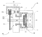
図1には、第1実施形態における車両駆動制御用アクチュエータA1を示す概略構成図が示されており、車両の左側後輪に搭載した状態を前方(車両進行方向)から視た図面である。図1に示されるように、車両駆動制御用アクチュエータA1は、電動モータ10と車輪駆動ユニット20と制動ユニット30と作動機構40とを備えて構成されている。
<First Embodiment>
FIG. 1 is a schematic configuration diagram showing a vehicle drive control actuator A1 in the first embodiment, and is a view of the state mounted on the left rear wheel of the vehicle as viewed from the front (vehicle traveling direction). As shown in FIG. 1, the vehicle drive control actuator A <b> 1 includes an
ハブステイ1内部に収容された電動モータ10は、駆動動力源としての機能と発電機としての機能を併せ持つモータであって、径方向外側に三相電機子巻線をもつ電機子としてのモータステータ11を、径方向内側に界磁磁石型回転子としてのモータロータ12を有する内転型(インナーロータ型)回転電機として機能する。
An
ハブステイ1内部に収容された車輪駆動ユニット20は、サンギア22と、複数個のプラネタリギア23と、リングギア24と、プラネタリキャリア25とを構成に含んだ遊星ギア減速機構21を備えている。
The
遊星ギア減速機構21は、サンギア22とリングギア24とに噛み合う複数個のプラネタリギア23をプラネタリキャリア25によって保持するものであり、電動モータ10が備えるモータシャフト(図示せず)の回転を減速して車両駆動軸26に伝達すると共に、動力を複数段に分配可能とする機能を有している。ここで、遊星ギア減速機構の中心に位置するサンギア22は、電動モータ10の備えるモータシャフト(図示せず)の端部に連結・固定される。
The planetary gear
各プラネタリギア23は、サンギア22の外周に噛合するように配設されており、各ギア23を軸支している各遊星軸(図示せず)によって、プラネタリキャリア25の径方向の両端部は、さらに軸支されている。プラネタリキャリア25の中心位置には、伝達された動力によって車輪を駆動するための車両駆動軸26が固定されている。そして、この車両駆動軸26は、ハブステイ1内部に設けられた軸受け(図示せず)によって回転可能に支持されている。
Each
リングギア24は、一方の端部側が、複数個の各プラネタリギア23の外周に設けられたギア歯面(外歯)とリングギア24の内周部に設けられたギア歯面(内歯)とが噛合するように配設されている。他方の端部側は、外周部に設けられたギア歯面(外歯)と作動機構40側に設けられたカウンタギア41の外周に設けられたギア歯面(外歯)とが噛合するように配設されている。そして、このリングギア24もまた、ハブステイ1内部に設けられた軸受け機構(図示せず)により、回動可能に支持されている。
One end side of the
次に上述した構成を備える車両駆動制御用アクチュエータA1の、車両走行時及び制動時における各部の作動について、図2を参照にしつつ説明する。図2は、図1に示された車両駆動制御用アクチュエータA1を図中矢印A方向から視た概略図が示されており、図2(a)は、車両走行時のリングギア24と、カウンタギア41を含む作動機構40との作動を、図2(b)は、制動時のリングギア24と、カウンタギア41を含む作動機構40との作動を示す説明図である。
Next, the operation of each part of the vehicle drive control actuator A1 having the above-described configuration during vehicle travel and braking will be described with reference to FIG. FIG. 2 is a schematic view of the vehicle drive control actuator A1 shown in FIG. 1 as viewed from the direction of the arrow A in FIG. 2. FIG. 2 (a) shows the
図2では、第1実施形態における作動機構40の作動を簡便に理解する為に、制動ユニット30が作動させる制動部材としてブレーキシューを用い、内部にブレーキシューが備えられたドラム型ブレーキを用いている。尚、本実施形態による作動機構40は、カウンタギア41と、連結材42、43とを備えて構成されている。カウンタギア41は、軸支点41aによって制動ユニット30へ回転可能に支持されている。連結材42は、外周にライニング材を備えたブレーキシュー32とリングギア24に噛合されたカウンタギア41とを連接しており、一端を支時点32bによってブレーキシュー32と、他端を支持点(43a、43b)によってリングギア24と回動可能に支持されている。連結材43は、リングギア24を中心に左右に対を成して配置された連結材42間を繋いでおり、カウンタギア41の軸支点41aを中心として径方向に対称を成す各支持点(43a、43b)間を連結して固定されている。
In FIG. 2, in order to easily understand the operation of the
車両走行時においては、図2(a)に示されるように、リングギア24は、遊星ギア減速機構21を介して分配されて伝達された電動モータ10の駆動力によって、サンギア22の接線力の反力を受けることにより、図中矢印Xで示された方向(反時計回り)に回動する。リングギア24と噛合されたカウンタギア41は、外周部に設けられたギア歯面を介して伝達された動力によって、リングギア24と反対方向(時計方向)に回動される。
When the vehicle travels, as shown in FIG. 2A, the
このカウンタギア41の回転に伴い、カウンタギア41へ固定された連結材43によって繋がれた連結材42の対には、それぞれに図中矢印Aで示された方向に対称的な作用力が働く。すなわち、右側のブレーキシュー32に連結する連結材42には43bを力点として左側方向へ作用力が働き、左側のブレーキシュー32に連結する連結材42には43aを力点として右側方向へ作用力が働く。結果、連結材42と支持点32bで連結された各ブレーキシュー32は、それぞれ、アンカーピン32aを支点として図中矢印Aで示された方向(内側方向)に引張られる状態となる。尚、戻りバネ33は、ブレーキシュー32と制動ユニット30との間に固定されており、ブレーキシュー33に対して、常に矢印Aで示された方向への作用力を生じさせている。
As the
車両走行中は、上述した状態を保ち続け、すなわち、ブレーキシュー32とドラム31間に制動力は生ずる事なしに、車両駆動軸26に分配・伝達された電動モータ10の動力によって車輪駆動が継続されることとなる。
While the vehicle is running, the above-described state is maintained, that is, the wheel drive is continued by the power of the
制動時においては、図2(b)に示されるように、リングギア24は、遊星ギア減速機構21を介して分配されて伝達された電動モータ10の回生力に基づいて、図中矢印Yで示された方向(時計回り)に回動する。駆動時と逆方向に回転するのは、回生力により、サンギア22の対する接線力の方向が逆転し、リングギアの受ける反力も逆転するためである。車両走行時と同様に、リングギア24と噛合されたカウンタギア41は、外周部に設けられたギア歯面を介して伝達された動力によって、リングギア24と反対方向(反時計方向)に回動されることとなる。
At the time of braking, as shown in FIG. 2B, the
そうすると、この車両走行時とは逆方向のカウンタギア41の回転に伴い、カウンタギア41へ固定された連結材43によって繋がれた連結材42の対には、それぞれに図中矢印Bで示された方向に対称的な作用力が働くこととなる。すなわち、右側のブレーキシュー32に連結する連結材42には43bを力点として右側方向へ作用力が働き、左側のブレーキシュー32に連結する連結材42には43aを力点として左側方向へ作用力が働く。結果、車両走行時とは対称的に逆方向に作用力が働くこととなり、連結材42と支持点32bで連結された各ブレーキシュー32は、それぞれ、アンカーピン32aを支点として図中矢印Bで示された方向(外側方向)に押出される状態となる。
Then, as the
押出された各ブレーキシュー32は、ライニング材を有する外周面がドラム31の内壁に押し付けられることとなり、各ブレーキシュー32/ドラム31間に摩擦力による制動力が発生する。当然の事ながら、この制動力は車両駆動軸26に分配・伝達された車輪駆動力とは逆向きに働くものであるため、車両進行方向に駆動している車輪は制動されることとなる。
Each of the pushed
このように、車輪駆動ユニット20に設けられた遊星ギア減速機構21が、電動モータ10からの動力を複数に分配し、この分配された動力によって制動ユニット30が備える作動機構40を駆動することにより、車輪駆動用の電動モータの動力を利用した簡単な構造で制動処理が実現できる。そして、簡単な構造であるため、部品点数は少なくて済み、構成部品の増加による重量増加を抑制できる。また、このような構成は電動モータ10の動力伝達軸)に近接させて構築できるため、所謂バネ下重量の軽減を可能とした、小型化、軽量化、低コスト化に適した車両駆動制御用アクチュエータA1が提供できる。
As described above, the planetary gear
尚、図2においては、リーディング・トレリーディングシューを用いたアンカーピン式のドラム型ブレーキを説明図として用いているが、例えば、制動部材であるブレーキシューを固定するアンカー部を、左右連結したリンクタイプであっても良いし、サーボ式や2リーディング式のタイプで構成されるものであっても良い。 In FIG. 2, an anchor pin type drum brake using a leading / treleading shoe is used as an explanatory diagram. For example, an anchor portion for fixing a brake shoe, which is a braking member, is connected to the left and right. It may be a type, or it may be a servo type or a two-reading type.
さらに、本発明は上述した実施の形態に限定されるものではなく、本発明の主旨を逸脱しない範囲で種々の変更を施すことが可能であることは云うまでもない。以下、本発明の変形例について説明する。 Furthermore, the present invention is not limited to the above-described embodiment, and it goes without saying that various modifications can be made without departing from the gist of the present invention. Hereinafter, modifications of the present invention will be described.
<第1実施形態の変形例>
図3には、第1実施形態に関する変形例が示されており、例えば、この実施形態による作動機構40は、カウンタギア41と、制動部材に当接可能な突出部を有するカム44とを備えて構成されている。
<Modification of First Embodiment>
FIG. 3 shows a modification of the first embodiment. For example, the
つまり、カウンタギア41は、軸支点41aによって制動ユニット30へ回転可能に支持されている。そして、制動部材に当接可能な突出部を有するカム44として、短軸長はカウンタギア径以下の大きさを、長軸長は少なくともカウンタギア径を超える大きさを有する楕円形状に構成されている。ここで、カム44は、軸支点41aを挟み左右(若しくは上下)に湾曲して突出する、制動部材に当接可能な楕円の頂点は互いに対称をなすように、軸支点41aによってカウンタギア41の回転に伴って回動可能に支持されている。
That is, the
このようなカム44を作動機構40に備えることにより、長軸方向の湾曲して突出する制動部材に当接可能な楕円の各頂点と、この各頂点に接する各ブレーキシュー32の摺動によって、第1実施形態に記述された作用効果と同等の効果を実現できる。
By providing such a
すなわち、車両走行時においては第1実施形態と同様に、図3(a)に示されるように、リングギア24は、遊星ギア減速機構21を介して分配され、伝達された電動モータ10の動力に基づいて、図中矢印Xで示された方向(反時計回り)に回動する。リングギア24と噛合されたカウンタギア41は、外周部に設けられたギア歯面を介して伝達された動力によって、軸支点41aを支点としてリングギア24と反対方向(時計方向)に回動される。
That is, when the vehicle is running, as in the first embodiment, as shown in FIG. 3A, the
このカウンタギア41の回転に伴って、カウンタギア41の軸支点41aと共通する軸支点で固定されたカム44も同一方向に回転する。すると、軸支点41aを挟んで左右に対称をなすように、カム44に接する各ブレーキシュー32には、それぞれに図中矢印Aで示された方向に対称的な作用力が働くこととなる。すなわち、右側のブレーキシュー32は、アンカーピン32aを支点として図中矢印Aで示された方向(右側→左側へ向かう内側方向)に摺動し、左側のブレーキシュー32も同様にアンカーピン32aを支点として図中矢印Aで示された方向(左側→右側へ向かう内側方向)に摺動されることとなる。
As the
車両走行中は、上述した状態を保ち続け(例えば、ストッパピン等による駆動範囲の制限)、ブレーキシュー32とドラム31との間には制動力を生ずる事なしに、車両駆動軸26に分配・伝達された電動モータ10の動力によって車輪駆動が継続される。
While the vehicle is running, the above-described state is maintained (for example, the driving range is limited by a stopper pin or the like), and the braking force is not generated between the
また、制動時においても第一実施形態と同様に、図3(b)に示されるよう、リングギア24は、遊星ギア減速機構21を介して分配され、伝達された電動モータ10の動力に基づいて、図中矢印Yで示された方向(時計回り)に回動する。そして、リングギア24と噛合されたカウンタギア41は、外周部に設けられたギア歯面を介して伝達された動力によって、リングギア24と反対方向(反時計方向)に回動される。
Also during braking, the
そして、車両走行時とは逆方向のカウンタギア41の回転に伴い、カウンタギア41の軸支点41aと共通する軸支点で固定されたカム44も同一方向に回転する。すると、軸支点41aを挟んで左右に対称をなすように、カム44に接する各ブレーキシュー32には、湾曲して突出した楕円の頂点によって、それぞれに図中矢印Bで示された方向に対称的な作用力が働くこととなる。
As the
すなわち、右側のブレーキシュー32には、アンカーとピン32aを支点として図中矢印Bで示された方向(左側→右側に向かう外側方向)に押し出され、左側のブレーキシュー32にも同様に、アンカーピン32aを支点として図中矢印Bで示された方向(右側→左側に向かう外側方向)に押し出される状態となる。
That is, the
外向きに押出された各ブレーキシュー32は、ライニング材を備えた外周面がドラム31の内壁に押し付けられることとなり、各ブレーキシュー32/ドラム31間に摩擦力による制動力が発生する。そして、この制動力は車両駆動軸26に分配・伝達された車輪駆動力とは逆向きに働くので、車両進行方向に駆動している車輪は制動されることとなる。
Each
このように、制動部材に当接可能な突出部を有する楕円形状のカム44をカウンタギア41の軸支点41aと共通(同軸)にさせ、回動可能に支持させることにより、第1実施形態と同様の作用効果を奏することができる。そして、第1実施形態の備える作動機構40よりも簡便であり、部品点数が少ないため、重量軽減、部品点数の軽減、低コスト化への寄与が、より効果的である。
In this way, the
<第2実施形態>
次に、図4及び図5に記載された図面を参照にしつつ、本発明の第2実施形態について説明する。第2実施形態では、制動ユニット30の構成形態と、作動機構40の構成形態とが第1実施形態と相違し、他は同様であるため、この相違点を主に説明する。
<Second Embodiment>
Next, a second embodiment of the present invention will be described with reference to the drawings described in FIGS. 4 and 5. In the second embodiment, the configuration form of the
図4には、第2実施形態における車両駆動制御用アクチュエータA1を示す概略構成図が示されており、車両の左側後輪に搭載した状態を前方(車両進行方向)から視た状態である。 FIG. 4 is a schematic configuration diagram showing the vehicle drive control actuator A1 in the second embodiment, which is a state in which the state mounted on the left rear wheel of the vehicle is viewed from the front (vehicle traveling direction).
制動ユニット30は、制動部材としてブレーキパッドを作動させる、ディスク型ブレーキを構成する。車両駆動軸26に連結・固定されたディスク34は、左右に配設されたパッド(35a、35b)で押圧され、挟持されることにより、車両駆動軸26に分配・伝達された車輪駆動力に対する制動力としている。各パッド(35a、35b)は、連結材(36a、36b)によってスプライン軸45a及びスプライン軸45bに連結された連結材46に支持・固定されている。
The
作動機構40は、カウンタギア41と、ヘリカルスプライン軸(45a、45b)と連結材46とを備えて構成されている。ここで、カウンタギア41はヘリカルスプライン軸(45a、45b)に対して回動可能に支持されている。ヘリカルスプライン軸45aは、連結材36aに連結されており、回動可能に支持されている。ヘリカルスプライン軸45bは、断面コ字状の連結材46に連結されており、回動可能に支持されている。そして、各ヘリカルスプライン軸に切られたヘリカル溝は、互いに逆向きとなるように形成されている。つまり、ヘリカルスプライン軸(45a、45b)は、カウンタギア41の回転を互いに逆向きな方向に作動する直線運動としての変換機能を有する直動機構として構築されている。
The
次に上述した構成による第2実施形態について、車両走行時及び制動時における各部の作動を、図5を参照にしつつ説明する。図5には、第2実施形態における車両駆動制御用アクチュエータA1の作動説明図が示されており、図5(a)は、車両走行時における作動機構40の作動を、図5(b)は、制動時における作動機構40の作動が示されている。
Next, in the second embodiment having the above-described configuration, the operation of each unit during vehicle travel and braking will be described with reference to FIG. FIG. 5 shows an operation explanatory diagram of the vehicle drive control actuator A1 in the second embodiment. FIG. 5 (a) shows the operation of the
車両走行時において、リングギア24は、第1実施形態と同様に、遊星ギア減速機構21を介して分配・伝達された電動モータ10の動力に基づいて、図2(a)中矢印Xで示された方向(反時計回り)に回動する。このリングギア24と噛合されたカウンタギア41は、外周部に設けられたギア歯面を介して伝達される動力によって、図5(a)中矢印Xで示されるようにリングギア24と反対方向(時計方向:図中では下向き矢印方向)に回動される。
When the vehicle travels, the
このカウンタギア41の回転に伴い、カウンタギア41の左側に設けられたヘリカルスプライン軸45aは、図中矢印Aで示された方向(左側→右側へ向かう方向)に引き込まれ、回動する。そして右側に設けられたヘリカルスプライン軸45bも、図中矢印Aで示された方向(右側→左側へ向かう方向)に引き込まれ、回動することとなる。
Along with the rotation of the
すると、ヘリカルスプライン軸45aと連結されたパッド35a及び連結材36aも、該軸45aの回動方向と動一方向に作動する。ヘリカルスプライン軸45bと連結材46を介して連結されたパッド35bと連結材36bも同様に、該軸45bの回動方向と同一方向に作動する。つまり、車両駆動軸26に連結・固定されたディスク34の左右に配設されたパッド(35a、35b)は互いに該ディスク34から離れる方向(解放方向)に作動する。
Then, the
車両走行中は、上述した状態を保ち続け(例えば、ストッパピン等による駆動範囲の制限)、ディスク34と各パッド(35a、35b)との間には制動力を生ずる事なしに、車両駆動軸26に分配・伝達された電動モータ10の動力によって車輪駆動が継続されることとなる。
While the vehicle is running, the above-described state is maintained (for example, the drive range is limited by a stopper pin or the like), and a braking force is not generated between the
一方、制動時においては、リングギア24は、第1実施形態と同様に、遊星ギア減速機構21を介して分配・伝達された電動モータ10の動力に基づいて、図2(b)中矢印Yで示された方向(時計回り)に回動する。このリングギア24に噛合されたカウンタギア41は、外周部に設けられたギア歯面を介して伝達される動力によって、図5(b)中矢印Yで示されるようにリングギア24と反対方向(反時計方向:図中では上向き矢印方向)に回動される。
On the other hand, during braking, the
このカウンタギア41の回転に伴い、カウンタギア41の左側に設けられたヘリカルスプライン軸45aは、図中矢印Bで示された方向(右側→左側へ向かう方向)に押し出され、回動する。そして左側に設けられたヘリカルスプライン軸45bも同様に、図中矢印Bで示された方向(左側→右側へ向かう方向)に押し出され、回動することとなる。
Along with the rotation of the
ヘリカルスプライン軸45aと連結されたパッド35a及び連結材36aも、該軸45aの回動方向と動一方向に作動し、ヘリカルスプライン軸45bと連結材46を介して連結されたパッド35bと連結材36bも同様に、該軸45bの回動方向と同一方向に作動し、車両駆動軸26に連結・固定されたディスク34の左右に配設されたパッド(35a、35b)は互いに該ディスク34を挟持して押圧する方向(締結方向)に作動することとなる。
The
ディスク34を挟んで互いに該ディスク34を押圧することとなった各パッド(35a、35b)と各パッド(35a、35b)間に挟まれるディスク34との間には摩擦力による制動力が発生する。そして、この制動力は車両駆動軸26に分配・伝達された車輪駆動力とは逆向きに働くので、車両進行方向に駆動している車輪は制動されることとなる。
A braking force due to a frictional force is generated between each pad (35a, 35b) that presses the
以上のように、第2実施形態では、リングギア24に噛合して回動するカウンタギア41と、カウンタギア41の回転を互いに逆向きとなる直線運動に変換する直動機構として構成されたヘリカルスプライン軸(45a、45b)と、連結材46とを備えて作動機構40を構成することにより、リングギア24の回動に伴って逆方向に回動するカウンタギア41の動力によって制動部材である各パッド(35a、35b)を作動させる、ディスク型ブレーキにも対応可能な車両駆動制御用アクチュエータA1が実現できる。
As described above, in the second embodiment, the
さらに、本発明は上述した実施の形態に限定されるものではなく、本発明の主旨を逸脱しない範囲で種々の変更を施すことが可能であることは云うまでもない。例えば、上述した第1及び第2、変形例での実施形態は遊星ギア減速機構21によって分配された動力によって駆動されているが、当然に、他の動力分配機構を用いても良い。本発明の作用効果は、このような動力分配機構の構成によるものではないからである。
Furthermore, the present invention is not limited to the above-described embodiment, and it goes without saying that various modifications can be made without departing from the gist of the present invention. For example, the first, second, and modified embodiments described above are driven by the power distributed by the planetary
A1:車両駆動用アクチュエータ
1:ハブステイ、 10:電動モータ、 11:モータステータ、 12:モータロータ
20:車輪駆動ユニット、 21:遊星ギア減速機構、 22:サンギア、23:プラネタリギア、 24:リングギア、 25:プラネタリキャリア、26:車両駆動軸
30:制動ユニット、 31:ドラム、 32:ブレーキシュー、 32a:アンカーピン、 32b:支持点、 33:戻りバネ、 34:ディスク、 35a、b:パッド
36a、b:連結材
40:作動機構、 41:カウンタギア、 41a:軸支点、 42、43:連結材、
43a、b:支持点、 44:カム、 45a、b:ヘリカルスプライン軸、 46:連結材
A1: Vehicle drive actuator 1: Hub stay 10: Electric motor 11: Motor stator 12: Motor rotor 20: Wheel drive unit 21: Planetary gear reduction mechanism 22: Sun gear 23: Planetary gear 24: Ring gear 25: Planetary carrier, 26: Vehicle drive shaft 30: Braking unit, 31: Drum, 32: Brake shoe, 32a: Anchor pin, 32b: Support point, 33: Return spring, 34: Disc, 35a, b:
43a, b: support point, 44: cam, 45a, b: helical spline shaft, 46: connecting material
Claims (11)
前記車両駆動ユニットは、前記電動モータからの動力を複数に分配可能な動力分配機構を備え、
前記動力分配機構を介して分配された動力によって前記制動部材を作動させるように構成される、
ことを特徴とする車両駆動制御用アクチュエータ。 A vehicle drive control actuator comprising: an electric motor; a wheel drive unit that transmits the rotation of the electric motor to an axle to rotate the wheel; and a braking member that applies a braking force to the wheel,
The vehicle drive unit includes a power distribution mechanism capable of distributing power from the electric motor to a plurality of units,
The braking member is configured to be operated by power distributed through the power distribution mechanism.
An actuator for vehicle drive control characterized by the above.
ことを特徴とする請求項1に記載の車両駆動制御用アクチュエータ。 The power distribution mechanism is constituted by a planetary gear mechanism capable of decelerating the rotation of the electric motor and transmitting it to the axle and distributing power.
The vehicle drive control actuator according to claim 1.
ことを特徴とする請求項2に記載の車両駆動制御用アクチュエータ。 An operating mechanism provided between the planetary gear mechanism and the braking member, and operating the power distributed through the planetary gear mechanism to the braking member;
The vehicle drive control actuator according to claim 2.
ことを特徴とする請求項3に記載の車両駆動制御用アクチュエータ。 The planetary gear mechanism is configured to input rotation of the electric motor to a sun gear, output rotation from a planetary carrier to the axle, and output power from a ring gear to the operating mechanism.
The vehicle drive control actuator according to claim 3.
ことを特徴とする請求項4に記載の車両駆動制御用アクチュエータ。 The actuating mechanism includes a counter gear that meshes with the ring gear and rotates, and a pair of connecting members that are rotatably fixed to the counter gear on one end side and the brake member on the other end side, respectively.
The vehicle drive control actuator according to claim 4.
ことを特徴とする請求項4に記載の車両駆動制御用アクチュエータ。 The actuating mechanism includes a counter gear that meshes with and rotates with the ring gear, and a cam member that is fixed so as to be rotatable coaxially with the counter gear and has a protrusion that can contact the braking member.
The vehicle drive control actuator according to claim 4.
ことを特徴とする請求項4に記載の車両駆動制御用アクチュエータ。 The operating mechanism includes a counter gear that meshes with the ring gear and rotates, and a linear motion mechanism that converts the rotation of the counter gear into a linear motion to operate the braking member.
The vehicle drive control actuator according to claim 4.
ことを特徴とする請求項1に記載の車両駆動制御用アクチュエータ。 An operating mechanism provided between the power distribution mechanism and the braking member, and operating the power distributed via the power distribution mechanism to the braking member;
The vehicle drive control actuator according to claim 1.
ことを特徴とする請求項8に記載の車両駆動制御用アクチュエータ。 The actuating mechanism includes a counter gear that is rotated by the output of the power distribution mechanism, and a pair of connecting members that are fixed to the counter gear on one end side and pivotally fixed to the brake member on the other end side, respectively.
The vehicle drive control actuator according to claim 8.
ことを特徴とする請求項8に記載の車両駆動制御用アクチュエータ。 The actuating mechanism includes a counter gear that meshes with the ring gear and is rotatable, and a cam member that is fixed so as to be rotatable coaxially with the counter gear and has a protrusion that can contact the braking member. ,
The vehicle drive control actuator according to claim 8.
ことを特徴とする請求項8に記載の車両駆動制御用アクチュエータ。 The operating mechanism includes a counter gear that meshes with the ring gear and rotates, and a linear motion mechanism that converts the rotation of the counter gear into a linear motion to operate the braking member.
The vehicle drive control actuator according to claim 8.
Priority Applications (1)
| Application Number | Priority Date | Filing Date | Title |
|---|---|---|---|
| JP2008191167A JP5228673B2 (en) | 2008-07-24 | 2008-07-24 | Vehicle drive control actuator |
Applications Claiming Priority (1)
| Application Number | Priority Date | Filing Date | Title |
|---|---|---|---|
| JP2008191167A JP5228673B2 (en) | 2008-07-24 | 2008-07-24 | Vehicle drive control actuator |
Publications (2)
| Publication Number | Publication Date |
|---|---|
| JP2010023806A true JP2010023806A (en) | 2010-02-04 |
| JP5228673B2 JP5228673B2 (en) | 2013-07-03 |
Family
ID=41730013
Family Applications (1)
| Application Number | Title | Priority Date | Filing Date |
|---|---|---|---|
| JP2008191167A Active JP5228673B2 (en) | 2008-07-24 | 2008-07-24 | Vehicle drive control actuator |
Country Status (1)
| Country | Link |
|---|---|
| JP (1) | JP5228673B2 (en) |
Cited By (3)
| Publication number | Priority date | Publication date | Assignee | Title |
|---|---|---|---|---|
| CN110454519A (en) * | 2019-08-28 | 2019-11-15 | 安徽理工大学 | A kind of vehicle electromechanical drum brake |
| KR20230034694A (en) * | 2021-09-03 | 2023-03-10 | 임병철 | Drum Brake For Vehicle |
| KR200496729Y1 (en) | 2021-09-03 | 2023-04-11 | 임병철 | Automotive drum brakes with improved brake shoe resilience |
Families Citing this family (1)
| Publication number | Priority date | Publication date | Assignee | Title |
|---|---|---|---|---|
| KR102006496B1 (en) * | 2017-09-29 | 2019-08-01 | 주식회사 만도 | Electronic parking brake |
Citations (3)
| Publication number | Priority date | Publication date | Assignee | Title |
|---|---|---|---|---|
| JP2006161952A (en) * | 2004-12-07 | 2006-06-22 | Advics:Kk | Brake device for vehicle |
| JP2007145071A (en) * | 2005-11-24 | 2007-06-14 | Toyota Motor Corp | Drive wheel structure for vehicle |
| JP2007276725A (en) * | 2006-04-11 | 2007-10-25 | Advics:Kk | Brake device for vehicle |
-
2008
- 2008-07-24 JP JP2008191167A patent/JP5228673B2/en active Active
Patent Citations (3)
| Publication number | Priority date | Publication date | Assignee | Title |
|---|---|---|---|---|
| JP2006161952A (en) * | 2004-12-07 | 2006-06-22 | Advics:Kk | Brake device for vehicle |
| JP2007145071A (en) * | 2005-11-24 | 2007-06-14 | Toyota Motor Corp | Drive wheel structure for vehicle |
| JP2007276725A (en) * | 2006-04-11 | 2007-10-25 | Advics:Kk | Brake device for vehicle |
Cited By (5)
| Publication number | Priority date | Publication date | Assignee | Title |
|---|---|---|---|---|
| CN110454519A (en) * | 2019-08-28 | 2019-11-15 | 安徽理工大学 | A kind of vehicle electromechanical drum brake |
| CN110454519B (en) * | 2019-08-28 | 2020-09-25 | 安徽理工大学 | Automobile electronic mechanical drum brake |
| KR20230034694A (en) * | 2021-09-03 | 2023-03-10 | 임병철 | Drum Brake For Vehicle |
| KR200496729Y1 (en) | 2021-09-03 | 2023-04-11 | 임병철 | Automotive drum brakes with improved brake shoe resilience |
| KR102526382B1 (en) | 2021-09-03 | 2023-04-26 | 임병철 | Drum Brake For Vehicle |
Also Published As
| Publication number | Publication date |
|---|---|
| JP5228673B2 (en) | 2013-07-03 |
Similar Documents
| Publication | Publication Date | Title |
|---|---|---|
| US8863920B2 (en) | Electronic parking brake | |
| US8292050B2 (en) | Electronic mechanical drum brake | |
| JP4280416B2 (en) | Drive unit for vehicle | |
| JP6007823B2 (en) | Wheel drive device | |
| JP2010230128A (en) | Brake device for in-wheel motor | |
| JP5228673B2 (en) | Vehicle drive control actuator | |
| CN102326010A (en) | Electromechanical arrangement for driving and/or braking shaft | |
| JP2013245736A (en) | Transmission for electric vehicle | |
| JP4659461B2 (en) | Vehicle wheel motor and control method thereof | |
| EP3715664A1 (en) | Brake system with torque distributing assembly | |
| JP6958536B2 (en) | Drive device for electric vehicle and electric vehicle | |
| KR101921409B1 (en) | Motor and brake system having the same | |
| JP6784203B2 (en) | Drive device | |
| JP6777003B2 (en) | Vehicle brake unit | |
| JP4328961B2 (en) | In-hole motor device | |
| JP4556650B2 (en) | Brake device for vehicle | |
| KR20140098920A (en) | Swing drive of Construction Machinery | |
| JP2018132088A (en) | Vehicle oil pump drive device | |
| JP2009120042A (en) | Drive device for hybrid vehicle | |
| JP2007056917A (en) | Electric disk brake | |
| JP6852634B2 (en) | Vehicle power unit | |
| JP7151967B2 (en) | Driving device and vehicle equipped with it | |
| KR20120031392A (en) | In wheel driven system | |
| JP2006199144A (en) | Driving device of vehicle | |
| CN210510252U (en) | Parking mechanism for vehicle |
Legal Events
| Date | Code | Title | Description |
|---|---|---|---|
| A621 | Written request for application examination |
Free format text: JAPANESE INTERMEDIATE CODE: A621 Effective date: 20101125 |
|
| A131 | Notification of reasons for refusal |
Free format text: JAPANESE INTERMEDIATE CODE: A131 Effective date: 20120828 |
|
| A977 | Report on retrieval |
Free format text: JAPANESE INTERMEDIATE CODE: A971007 Effective date: 20120831 |
|
| A521 | Written amendment |
Free format text: JAPANESE INTERMEDIATE CODE: A523 Effective date: 20121024 |
|
| TRDD | Decision of grant or rejection written | ||
| A01 | Written decision to grant a patent or to grant a registration (utility model) |
Free format text: JAPANESE INTERMEDIATE CODE: A01 Effective date: 20130219 |
|
| A61 | First payment of annual fees (during grant procedure) |
Free format text: JAPANESE INTERMEDIATE CODE: A61 Effective date: 20130304 |
|
| FPAY | Renewal fee payment (event date is renewal date of database) |
Free format text: PAYMENT UNTIL: 20160329 Year of fee payment: 3 |
|
| R151 | Written notification of patent or utility model registration |
Ref document number: 5228673 Country of ref document: JP Free format text: JAPANESE INTERMEDIATE CODE: R151 |
|
| R250 | Receipt of annual fees |
Free format text: JAPANESE INTERMEDIATE CODE: R250 |
|
| R250 | Receipt of annual fees |
Free format text: JAPANESE INTERMEDIATE CODE: R250 |
|
| R250 | Receipt of annual fees |
Free format text: JAPANESE INTERMEDIATE CODE: R250 |
|
| R250 | Receipt of annual fees |
Free format text: JAPANESE INTERMEDIATE CODE: R250 |
|
| R250 | Receipt of annual fees |
Free format text: JAPANESE INTERMEDIATE CODE: R250 |