EP3715664A1 - Brake system with torque distributing assembly - Google Patents
Brake system with torque distributing assembly Download PDFInfo
- Publication number
- EP3715664A1 EP3715664A1 EP20163390.6A EP20163390A EP3715664A1 EP 3715664 A1 EP3715664 A1 EP 3715664A1 EP 20163390 A EP20163390 A EP 20163390A EP 3715664 A1 EP3715664 A1 EP 3715664A1
- Authority
- EP
- European Patent Office
- Prior art keywords
- brake
- gear
- axis
- piston
- rotate
- Prior art date
- Legal status (The legal status is an assumption and is not a legal conclusion. Google has not performed a legal analysis and makes no representation as to the accuracy of the status listed.)
- Granted
Links
- 238000004891 communication Methods 0.000 claims description 6
- 230000007246 mechanism Effects 0.000 description 21
- 239000012530 fluid Substances 0.000 description 4
- 239000002783 friction material Substances 0.000 description 4
- 238000000034 method Methods 0.000 description 3
- 230000015556 catabolic process Effects 0.000 description 2
- 238000006731 degradation reaction Methods 0.000 description 2
- 230000000994 depressogenic effect Effects 0.000 description 2
- 238000006243 chemical reaction Methods 0.000 description 1
- 150000001875 compounds Chemical class 0.000 description 1
- 230000003247 decreasing effect Effects 0.000 description 1
- 210000005069 ears Anatomy 0.000 description 1
- 230000003993 interaction Effects 0.000 description 1
- 238000004806 packaging method and process Methods 0.000 description 1
Images


Classifications
-
- F—MECHANICAL ENGINEERING; LIGHTING; HEATING; WEAPONS; BLASTING
- F16—ENGINEERING ELEMENTS AND UNITS; GENERAL MEASURES FOR PRODUCING AND MAINTAINING EFFECTIVE FUNCTIONING OF MACHINES OR INSTALLATIONS; THERMAL INSULATION IN GENERAL
- F16D—COUPLINGS FOR TRANSMITTING ROTATION; CLUTCHES; BRAKES
- F16D65/00—Parts or details
- F16D65/14—Actuating mechanisms for brakes; Means for initiating operation at a predetermined position
- F16D65/16—Actuating mechanisms for brakes; Means for initiating operation at a predetermined position arranged in or on the brake
- F16D65/18—Actuating mechanisms for brakes; Means for initiating operation at a predetermined position arranged in or on the brake adapted for drawing members together, e.g. for disc brakes
- F16D65/183—Actuating mechanisms for brakes; Means for initiating operation at a predetermined position arranged in or on the brake adapted for drawing members together, e.g. for disc brakes with force-transmitting members arranged side by side acting on a spot type force-applying member
-
- B—PERFORMING OPERATIONS; TRANSPORTING
- B60—VEHICLES IN GENERAL
- B60T—VEHICLE BRAKE CONTROL SYSTEMS OR PARTS THEREOF; BRAKE CONTROL SYSTEMS OR PARTS THEREOF, IN GENERAL; ARRANGEMENT OF BRAKING ELEMENTS ON VEHICLES IN GENERAL; PORTABLE DEVICES FOR PREVENTING UNWANTED MOVEMENT OF VEHICLES; VEHICLE MODIFICATIONS TO FACILITATE COOLING OF BRAKES
- B60T13/00—Transmitting braking action from initiating means to ultimate brake actuator with power assistance or drive; Brake systems incorporating such transmitting means, e.g. air-pressure brake systems
- B60T13/74—Transmitting braking action from initiating means to ultimate brake actuator with power assistance or drive; Brake systems incorporating such transmitting means, e.g. air-pressure brake systems with electrical assistance or drive
- B60T13/746—Transmitting braking action from initiating means to ultimate brake actuator with power assistance or drive; Brake systems incorporating such transmitting means, e.g. air-pressure brake systems with electrical assistance or drive and mechanical transmission of the braking action
-
- F—MECHANICAL ENGINEERING; LIGHTING; HEATING; WEAPONS; BLASTING
- F16—ENGINEERING ELEMENTS AND UNITS; GENERAL MEASURES FOR PRODUCING AND MAINTAINING EFFECTIVE FUNCTIONING OF MACHINES OR INSTALLATIONS; THERMAL INSULATION IN GENERAL
- F16D—COUPLINGS FOR TRANSMITTING ROTATION; CLUTCHES; BRAKES
- F16D55/00—Brakes with substantially-radial braking surfaces pressed together in axial direction, e.g. disc brakes
- F16D55/02—Brakes with substantially-radial braking surfaces pressed together in axial direction, e.g. disc brakes with axially-movable discs or pads pressed against axially-located rotating members
- F16D55/22—Brakes with substantially-radial braking surfaces pressed together in axial direction, e.g. disc brakes with axially-movable discs or pads pressed against axially-located rotating members by clamping an axially-located rotating disc between movable braking members, e.g. movable brake discs or brake pads
- F16D55/224—Brakes with substantially-radial braking surfaces pressed together in axial direction, e.g. disc brakes with axially-movable discs or pads pressed against axially-located rotating members by clamping an axially-located rotating disc between movable braking members, e.g. movable brake discs or brake pads with a common actuating member for the braking members
-
- F—MECHANICAL ENGINEERING; LIGHTING; HEATING; WEAPONS; BLASTING
- F16—ENGINEERING ELEMENTS AND UNITS; GENERAL MEASURES FOR PRODUCING AND MAINTAINING EFFECTIVE FUNCTIONING OF MACHINES OR INSTALLATIONS; THERMAL INSULATION IN GENERAL
- F16D—COUPLINGS FOR TRANSMITTING ROTATION; CLUTCHES; BRAKES
- F16D65/00—Parts or details
- F16D65/14—Actuating mechanisms for brakes; Means for initiating operation at a predetermined position
- F16D65/16—Actuating mechanisms for brakes; Means for initiating operation at a predetermined position arranged in or on the brake
- F16D65/18—Actuating mechanisms for brakes; Means for initiating operation at a predetermined position arranged in or on the brake adapted for drawing members together, e.g. for disc brakes
-
- F—MECHANICAL ENGINEERING; LIGHTING; HEATING; WEAPONS; BLASTING
- F16—ENGINEERING ELEMENTS AND UNITS; GENERAL MEASURES FOR PRODUCING AND MAINTAINING EFFECTIVE FUNCTIONING OF MACHINES OR INSTALLATIONS; THERMAL INSULATION IN GENERAL
- F16D—COUPLINGS FOR TRANSMITTING ROTATION; CLUTCHES; BRAKES
- F16D2121/00—Type of actuator operation force
- F16D2121/02—Fluid pressure
- F16D2121/04—Fluid pressure acting on a piston-type actuator, e.g. for liquid pressure
-
- F—MECHANICAL ENGINEERING; LIGHTING; HEATING; WEAPONS; BLASTING
- F16—ENGINEERING ELEMENTS AND UNITS; GENERAL MEASURES FOR PRODUCING AND MAINTAINING EFFECTIVE FUNCTIONING OF MACHINES OR INSTALLATIONS; THERMAL INSULATION IN GENERAL
- F16D—COUPLINGS FOR TRANSMITTING ROTATION; CLUTCHES; BRAKES
- F16D2121/00—Type of actuator operation force
- F16D2121/18—Electric or magnetic
- F16D2121/24—Electric or magnetic using motors
-
- F—MECHANICAL ENGINEERING; LIGHTING; HEATING; WEAPONS; BLASTING
- F16—ENGINEERING ELEMENTS AND UNITS; GENERAL MEASURES FOR PRODUCING AND MAINTAINING EFFECTIVE FUNCTIONING OF MACHINES OR INSTALLATIONS; THERMAL INSULATION IN GENERAL
- F16D—COUPLINGS FOR TRANSMITTING ROTATION; CLUTCHES; BRAKES
- F16D2123/00—Multiple operation forces
-
- F—MECHANICAL ENGINEERING; LIGHTING; HEATING; WEAPONS; BLASTING
- F16—ENGINEERING ELEMENTS AND UNITS; GENERAL MEASURES FOR PRODUCING AND MAINTAINING EFFECTIVE FUNCTIONING OF MACHINES OR INSTALLATIONS; THERMAL INSULATION IN GENERAL
- F16D—COUPLINGS FOR TRANSMITTING ROTATION; CLUTCHES; BRAKES
- F16D2125/00—Components of actuators
- F16D2125/18—Mechanical mechanisms
- F16D2125/20—Mechanical mechanisms converting rotation to linear movement or vice versa
- F16D2125/34—Mechanical mechanisms converting rotation to linear movement or vice versa acting in the direction of the axis of rotation
- F16D2125/40—Screw-and-nut
-
- F—MECHANICAL ENGINEERING; LIGHTING; HEATING; WEAPONS; BLASTING
- F16—ENGINEERING ELEMENTS AND UNITS; GENERAL MEASURES FOR PRODUCING AND MAINTAINING EFFECTIVE FUNCTIONING OF MACHINES OR INSTALLATIONS; THERMAL INSULATION IN GENERAL
- F16D—COUPLINGS FOR TRANSMITTING ROTATION; CLUTCHES; BRAKES
- F16D2125/00—Components of actuators
- F16D2125/18—Mechanical mechanisms
- F16D2125/44—Mechanical mechanisms transmitting rotation
- F16D2125/46—Rotating members in mutual engagement
- F16D2125/48—Rotating members in mutual engagement with parallel stationary axes, e.g. spur gears
-
- F—MECHANICAL ENGINEERING; LIGHTING; HEATING; WEAPONS; BLASTING
- F16—ENGINEERING ELEMENTS AND UNITS; GENERAL MEASURES FOR PRODUCING AND MAINTAINING EFFECTIVE FUNCTIONING OF MACHINES OR INSTALLATIONS; THERMAL INSULATION IN GENERAL
- F16D—COUPLINGS FOR TRANSMITTING ROTATION; CLUTCHES; BRAKES
- F16D2125/00—Components of actuators
- F16D2125/18—Mechanical mechanisms
- F16D2125/44—Mechanical mechanisms transmitting rotation
- F16D2125/46—Rotating members in mutual engagement
- F16D2125/50—Rotating members in mutual engagement with parallel non-stationary axes, e.g. planetary gearing
Definitions
- These teachings relate to a brake system, and more particularly to a torque distributing assembly for distributing torque between two or more brake pistons.
- Some vehicles utilize multi-piston brake systems to create a clamping force to slow, stop, and/or maintain a vehicle in a stopped or parked position.
- multiple motors are used to move the brake pistons to create and release the clamping force.
- the brake system may be a system or assembly for creating a clamping force.
- the brake system may be any system or assembly for releasing a clamping force.
- the brake system may function to, may be configured to, or may be adapted or enabled to create a clamping force to slow, stop, and/or maintain a vehicle in a stopped position.
- the brake system may be an opposed brake system (i.e., a fixed caliper brake system) or a floating brake system (i.e., a floating caliper).
- the brake system may be a disc brake system.
- the brake system may be a drum brake system.
- the brake system may be a service brake system.
- the brake system may be a parking brake system.
- the clamping force may be a force that, when coupled with a brake pad or brake shoe coefficient of friction, functions to decelerate, slow, stop, and/or prevent movement or rotation of a brake rotor, brake drum, and/or a vehicle.
- the clamping force may be created during a standard brake apply (i.e., a brake apply force).
- the clamping force may be created during a parking brake apply (i.e., a parking brake force).
- the brake system may include one or more brake pads, and a brake caliper supporting two or more brake pistons.
- the two or more brake pistons may be moved towards and away from the one or more brake pads by pressurizing brake fluid.
- the two or more brake pistons and one or more brake pads may be moved with electromechanical elements to create clamping force.
- the electromechanical elements may include rotary to linear mechanisms, spindle, nut, motor, one or more gears, a torque distributing assembly, or a combination thereof.
- the brake rotor may cooperate with the components of the brake system to create the clamping force.
- the brake rotor may include an inboard side and an opposing outboard side.
- the brake caliper may be arranged so that one or more brake pads are located at the inboard side of the brake rotor (i.e., inboard brake pads), and one or more brake pads are located at the outboard side of the brake rotor (i.e., outboard brake pads), or both.
- the brake caliper may have two or more piston bores. Each piston bore may define a hollow region in the brake caliper configured to receive and support a corresponding brake piston.
- the piston bores can be located entirely on one side of the brake rotor, or on both sides of the brake rotor.
- the brake pistons may be moved by pressurizing fluid, such as brake fluid.
- pressurizing fluid such as brake fluid.
- the brake piston can be moved by depressurizing the fluid.
- the brake pistons may be moved with one or more electromechanical mechanisms (e.g., with one or more rotary to linear mechanisms; spindles; nuts; motors, etc.).
- electromechanical mechanisms e.g., with one or more rotary to linear mechanisms; spindles; nuts; motors, etc.
- the one or more brake pads may be used to create the clamping force.
- the clamping force can be created by converting the kinetic energy of the vehicle into thermal energy by frictionally engaging one or more brake pads with one or more sides of the brake rotor.
- the one or more brake pads may include one or more features (i.e. ears, projections, etc.) that may engage or be engaged by a brake caliper, a support bracket, or both to maintain the location of the brake pads within the braking system and relative to the brake rotor.
- the brake piston may move in an oppose, release direction, so that the brake pad can then move away from the brake rotor to release the clamping force.
- the motor may be any motor for creating a force or torque.
- the motor may be a DC motor, a brushless motor, a series-wound motor, a shunt wound motor, a compound wound motor, a separately exited motor, a servomotor, a stepping motor, or a permanent magnet motor.
- the motor may include one or more electrical leads for connecting the motor to a power source. Supplying power to the motor may cause the output shaft of the motor to rotate about an axis.
- the output shaft rotation may be adapted for an apply direction (to create a clamping force) and for a release direction (to release a clamping force).
- the brake system may comprise one or more rotary to linear mechanisms.
- the one or more rotary to linear mechanisms may function to convert a torque output from the motor or torque distributing assembly into a linear or axial force to move the one or more brake pistons.
- the one or more rotary to linear mechanisms may be a high-efficiency device such as a ball screw, a roller screw, or a ball ramp, for example.
- the one or more rotary to linear mechanisms may be a low-efficiency device.
- the one or more rotary to linear mechanisms may generally include a spindle and a nut.
- the spindle may be rotated by the motor or corresponding driving gear.
- the spindle may be rotated in an apply direction and a release direction to apply and release the brake system brake, respectively.
- Rotation of the spindle may cause a nut that is threadably engaged with the spindle to move axially along an axis in an apply or release direction to move the brake pad towards or away from a brake rotor.
- the torque distributing assembly may function to transfer or distribute an output torque from a motor or gear train to or amongst two or more brake pistons or rotary to linear mechanisms during a brake apply, a parking brake apply, or both to create a clamping force.
- the torque distributing assembly may function to transfer or distribute an output torque from a motor or gear train to or amongst two or more brake pistons or rotary to linear mechanism during a brake release, a parking brake release, or both to release a clamping force.
- the torque distributing assembly may be configured to distribute torque from the motor generally equally to both of the first brake piston and the second brake piston so that both of the brake pistons are moved unison until a resistance on one of the two brake pistons becomes higher than the other brake piston.
- the torque distributing assembly may then be configured to distribute power from the motor to the brake piston with the lower resistance so that the piston assembly with the higher resistance slows or ceases to move
- the torque distributing assembly is configured to reduce a torque supply to that brake piston and then redistribute the torque supply to the other brake piston so that the other corresponding end of the brake pad is moved towards and into contact with the brake rotor. Accordingly, with these teachings, a single motor can be used to move multiple brake pistons to create a clamping force.
- uneven or different loads or forces acting on the brake pistons may be a result of uneven or warped brake rotor surfaces.
- the torque distributing assembly may include one or more drive gears.
- the one or more drive gears may function to transfer torque from the motor or torque distributing assembly to the corresponding spindle.
- the drive gear may frictionally engage a corresponding spindle.
- the drive gear may engage a corresponding spindle via spines and corresponding notches defined on the spindle and drive gear.
- Two or more of the drive gears may be aligned along and/or configured to rotate about a common axis. Two or more of the drive gears may be aligned within a common plane. Two drive gears may be located in a common plane and two drive gears may be located in another plane, wherein one drive gear is located in both planes, and both planes are generally perpendicular to one another. Two or more of the drive gears may be connected via a belt, chain, or another gear so that rotation of one gear causes another gear to rotate.
- the torque distributing assembly may include a plurality of planet gears and sun gears located between two drive gears.
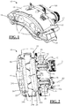
- FIG. 1 illustrates a brake system 10.
- the brake system 10 comprises a brake caliper 12.
- the brake caliper 12 comprises an inboard side 13, an outboard side 14, and a bridge 15 connecting the inboard and outboard sides 13, 14.
- Inboard refers to the orientation of the brake caliper 12 relative to a brake rotor or road wheel.
- the inboard side 13 is on the inboard side of the brake rotor and the outboard side 14 is on the outboard side of the brake rotor.
- the outboard side 14 or bridge 15 has fingers 16.
- the brake system 10 comprises a support bracket 18 that is configured to connect the brake system 10 and/or brake caliper 12 to a stationary part of a vehicle, like a knuckle.
- the brake system 10 comprises a torque distributing assembly 100.
- FIG. 2 illustrates the brake system 10.
- the brake caliper 12 is configured to support an inboard brake pad 20 and an opposing outboard brake pad 22.
- Each brake pad 20, 22 comprises a friction material 24a, 24b and a pressure plate 26a, 26b.
- a brake rotor is configured to be provided between the friction materials 24a, 24b of the brake pads 20, 22. Contact between the friction material 24a, 24b and the brake rotor creates or generates clamping force to slow, stop, or prevent movement of a brake rotor, road wheel, and/or vehicle.
- the brake caliper 12 is configured to support one or more brake pistons (e.g. first and second brake pistons 28, 30).
- the brake pistons 28, 30 are supported or located on the same side of the brake caliper 12 (i.e., on the inboard side 13).
- the brake pistons 28, 30 are configured to contact or engage the pressure plate 26a of the inboard brake pad 20.
- the fingers 16 of the bridge 15 ( FIG. 1 ) are configured to contact or engage the pressure plate 26B of the outboard brake pad 22.
- Each brake piston 28, 30 comprises a piston pocket 32a, 32b.
- a first rotary to linear mechanism 34 is at least partially received into the piston pocket 32a of the first brake piston 28, and a second rotary to linear mechanism 36 is at least partially received into the piston pocket 32b of the second brake piston 30.
- the first rotary to linear mechanism 34 comprises a first spindle 38 and a first nut 40.
- the first spindle 38 is threadably engaged with the first nut 40 such that rotation of the first spindle 38 about a spindle axis (also referred to herein as longitudinal axis A3) causes the first nut 40 to move.
- the first nut 40 is restricted or prevented from rotating inside of the piston pocket 32a about axis A3; thus, rotation of the first spindle 40 causes the first nut 38 to move axially within the piston pocket 32a along the axis A3.
- the second rotary to linear mechanism 36 comprises a second spindle 42 and a second nut 44.
- the second spindle 42 is threadably engaged with the second nut 44 such that rotation of the second spindle 42 about a spindle axis (also referred to herein as longitudinal axis A) causes the second nut 44 to move.
- the second nut 44 is restricted or prevented from rotating inside of the piston pocket 32b about axis A; thus, rotation of the second spindle 42 causes the second nut 44 to move axially within the piston pocket 32b along axis A.
- FIG. 3 illustrates the torque distributing assembly 100, the first and second brake pistons 28, 30, and a motor 46.
- the motor 46 may be part of the torque distributing assembly 100, the brake system 10, or both.
- the motor 46 is located in between the first brake piston 28 and the second brake piston 30.
- the first brake piston 28 extends along longitudinal axis A; the second brake piston 30 extends along longitudinal axis A3; and the motor 46 and motor output 48 extends along longitudinal axis A4.
- the longitudinal axis A, A3, and A4 are all generally parallel to one another.
- the axis A4 is also parallel to the axis A about which the gear set 126 is configured to rotate about.
- the torque distributing assembly 100 comprises a first driving gear 102, a second driving gear 104, and a third driving gear 106.
- the first and second driving gears 102, 104 are concentrically aligned and configured to rotate about a common axis A (See also FIGs. 2 and 4 ) in an apply and release direction (i.e., clockwise and counterclockwise, or vice versa).
- the common axis A may be the same axis that the second brake piston 30 extends along and also moves along in an apply and release direction.
- the common axis A may be the same axis A about which the second spindle 42 is configured to rotate about and the same axis A that the second nut 44 moves axially along in an apply and release direction.
- the second and third driving gears 104, 106 are arranged adjacent to one another or juxtaposed to one another.
- the second and third driving gears 104, 106 may be arranged in a common plane.
- the second and third driving gears 104, 106 are connected together via a connecting member 108, which may be a belt, chain, strap, or other suitable connecting member such as an intermediate gear or member.
- the connecting member 108 By way of the connecting member 108, the second and third gears 104, 106 are configured to also rotate together in an apply and release direction. That is, rotation of the second driving gear 104 causes the third driving gear 106 to rotate.
- the third gear 106 may be configured to rotate about an axis A3 that may be the same axis A3 about which the first spindle 38 is configured to rotate about in an apply and release direction ( FIG. 2 ), the axis that the first nut 40 is configured to axially move along in an apply and release direction, and the axis that the first brake piston 28 moves along in an apply and release direction.
- FIG. 4 illustrates the torque distributing assembly 100 and the first and second brake pistons 28, 30.
- the torque distributing assembly 100 comprises a plurality of first planet gears 110, a plurality of second planet gears 112, a first sun gear 114, and a second sun gear 116, all of which are located between the first and second driving gears 102, 104.
- the first and second planet gears 110, 112 are supported on pins or shafts that are configured to engage both of the first and second driving gears 102, 104 and surround the first and second sun gears 114, 116.
- the first sun gear 114 may be combined with or integrated with the first driving gear 102 into a single gear or mechanism.
- the second sun gear 116 comprises an engagement section 118 that is configured to engage an engagement section 120 of the spindle 42 so that rotation of the second sun gear 116 about axis A causes the spindle 42 to rotate about axis A.
- the third driving gear 106 comprises an engagement section that is configured to engage an engagement section 122 of the spindle 38 so that rotation of third driving gear 106 about axis A3 causes the spindle 38 to rotate about axis A3.
- the torque transferring assembly includes a gear set 126 that includes the first driving gear 102, the first sun gear 114, the first and second planet gears 110, 112, the second sun gear 116, and the second driving gear 104.
- a gear set 126 that includes the first driving gear 102, the first sun gear 114, the first and second planet gears 110, 112, the second sun gear 116, and the second driving gear 104.
- the clamping force may be created during application of the service brake to slow or stop a brake rotor, road wheel, and/or vehicle.
- the clamping force may be created during application of the parking brake to restrict or prevent movement of the brake rotor, road wheel, and/or vehicle.
- the clamping force may be created during application of both the service brake and the parking brake.
- the torque distributing assembly 100 is inactive, which means a force, load, or resistance acting on two or more of the brake pistons is generally the same or equal, and thus the torque distributing assembly 100 is configured to distribute torque generally equal torque to each of the two or more brake pistons at the same time so that the brake pistons 28, 30 are moved at generally the same time.
- the method includes a step of turning ON the system 10 and/or the motor 46.
- Turning ON the system 10 and/or motor 46 means supplying the system 10 and/or the motor 46 with power or current. Turning ON the system 10 and/or motor may occur after a pedal, lever, or other button is moved or depressed and/or when the vehicle is put into park gear or turned OFF, for example.
- Apply direction torque is an output of torque from the motor 46 via output gear 48 ( FIG. 3 ) which is then transferred via the gears 52 in the gear train 50 to the first driving gear 102, which causes the first driving gear 102 to rotate in the apply direction about axis A.
- Apply direction as used herein may be clockwise or counterclockwise about the respective axis.
- Rotation of the first driving gear 102 in the apply direction about axis A causes the first sun gear 114 to rotate in the apply direction about axis A.
- Rotation of the first driving gear 102 and rotation of the first sun gear 114 in the apply direction about axis A functions to apply a force or torque onto the first planet gears 110, causing the first planet gears 110 to rotate with the first driving gear 104 and the first sun gear 114 in the apply direction about axis A.
- Rotation of the second planet gears 112 in the apply direction about axis A functions to apply a force or torque onto the second sun gear 116 causing the second sun gear 116 to rotate about axis A in the apply direction.
- the second sun gear 116 is in communication with the second spindle 42. Therefore, rotation of the second sun gear 116 about axis A in the apply direction causes the second spindle 42 to rotate about axis A in the apply direction.
- the second nut 44 located inside of the second brake piston 30 is threadably engaged with the second spindle 42 and restricted or prevented from rotating about axis A. Therefore, rotation of the second spindle 42 in the apply direction about axis A via the second sun gear 116 causes the second nut 44 to move axially along axis A in an apply direction towards a bottom wall of the second piston pocket 32b of the second brake piston 30 until an end of the second nut 44 contacts the bottom pocket wall of the second piston pocket 32b.
- rotation of the second planet gears 112 in the apply direction about axis A also causes the second driving gear 104 to rotate about the axis A in the apply direction.
- Rotation of the second driving gear 104 about the axis A in the apply direction causes the third driving gear 106 to rotate about its axis A3 in the apply direction by way of the connecting member 108.
- the third driving gear 106 is in communication with the first spindle 38 so that rotation of the third driving gear 106 in the apply direction causes the first spindle 38 to rotate about axis A3 in the apply direction.
- the first nut 40 located inside of the first brake piston 28 is threadably engaged with the first spindle 38 and restricted or prevented from rotating about axis A3. Therefore, rotation of the first spindle 38 in the apply direction about axis A3 via the third driving gear 106 causes the first nut 40 to move axially along axis A3 in an apply direction towards a bottom wall of the first piston pocket 32a of the first brake piston 28 until an end of the first nut 40 contacts the bottom pocket wall of the first piston pocket 32a.
- the torque distributing assembly 100 is active, which means a force, load, or resistance acting on two or more of the brake pistons is different or not equal. That is, if or when or after a force, load, or resistance acting on one of the brake pistons 28, 30 becomes higher than a force, load, or resistance acting on the other brake pistons 28, 30, the torque distributing assembly 100 is activated.
- the first spindle 38 slows or ceases to rotate.
- the third driving gear 106 correspondingly slows or ceases to rotate about axis A3.
- the second driving gear 104 correspondingly slows or ceases to rotate about axis A due to the connecting member 108 connecting together the second and third driving gears 104, 106.
- the slowing or ceasing of rotation of the second driving gear 104 about axis A causes the second planet gears 112 to slow or cease rotating about axis A.
- the apply direction torque from the motor 46 continues to be supplied to the assembly 100. Therefore, the apply direction torque transmitted by the first driving gear 102 to the first planet gears 110 and to the second planet gears 112 causes the second planet gears 112 to spin about each of their axis A2 so that torque or force is transmitted to the second sun gear 116 thus causing the second sun gear 116 to continue rotating about axis A in the apply direction.
- the second spindle 42 slows or ceases to rotate.
- the second sun gear 116 correspondingly slows or ceases to rotate.
- the apply direction torque from the motor 46 continues to be supplied to the assembly 100. Accordingly, the apply direction torque transmitted by the first driving gear 102 and the first planet gears 110 to the second planet gears 112 while the second sun gear 116 is slowed or ceased rotating causes the second planet gears 112 to spin about their axis A2 while the second planet gears 112 continued to rotate about axis A.
- the second driving gear 104 can continue to rotate with the second planet gears 112 about axis A, which provides for the third driving gear 106 to rotate about axis A3 by way of the connecting member 108, so that the second spindle 38 is rotated in the apply direction.
- Rotation of the second spindle 42 in the apply direction continues to move the second nut 44 in the apply direction, which moves the second brake piston 30 in the apply direction, which then moves the inboard brake pad 20 against the brake rotor to generate clamping force.
- the clamping force may be released so that the brake rotor, road wheel, and/or vehicle can one again move.
- the method includes a step of turning ON the system 10 and/or the motor 46. This may occur, for example, after a pedal, lever, or other button is moved or depressed and/or when the vehicle is put into drive gear, for example.
- the motor 46 After the system 10 and/or the motor 46 is turned ON, power or current is supplied to the motor 46, which turns the motor 46 ON and the motor 46 generates a release direction torque, which is opposite the direction of the apply direction torque.
- the release direction torque is output from the motor 46 via output gear 48 and then transferred via the gears 52 in the gear train 50 to the first driving gear 102, which causes the first driving gear 102 to rotate in the release direction about axis A.
- Rotation of the first driving gear 102 in the release direction about axis A causes the first sun gear 114 to rotate in the release direction about axis A.
- Rotation of the first sun gear 114 in the release direction about axis A functions to apply a force onto the first planet gears 110, causing the first planet gears 110 to rotate with the first driving gear 104 and the first sun gear 114 in the release direction about axis A.
- Rotation of the first planet gears 110 in the release direction functions to apply a force onto the second planet gears 112 causing the second planet gears 112 to rotate with the first planet gears 110, the first driving gear 104, and the first sun gear 114 in the release direction about axis A.
- the second sun gear 116 is in communication with the second spindle 42. Therefore, rotation of the second sun gear 116 about axis A in the release direction causes the second spindle 42 to rotate about axis A in the release direction.
- Rotation of the second spindle 42 in the release direction about axis A via the second sun gear 116 causes the second nut 44 to move axially along axis A in a release direction away from the bottom wall of the second piston pocket 32b of the second brake piston 30 so that the second brake piston 30 moves away from the inboard brake pad 20 and the inboard brake pad 20 can be pulled out of contact with the brake rotor thus releasing the clamping force.
- Rotation of the second planet gears 112 in the release direction about axis A also causes the second driving gear 104 to rotate about the axis A in the ap release ply direction.
- Rotation of the second driving gear 104 about the axis A in the release direction causes the third driving gear 106 to rotate about its axis A3 in the release direction by way of the connecting member 108.
- the third driving gear 106 is in communication with the first spindle 38 so that rotation of the third driving gear 106 in the release direction causes the first spindle 38 to rotate about axis A3 in the release direction.
- Rotation of the first spindle 38 in the release direction about axis A3 via the third driving gear 106 causes the first nut 40 to move axially along axis A3 in a release direction away from the bottom wall of the first piston pocket 32a of the first brake piston 28 so that the first brake piston 28 moves away from the inboard brake pad 20 and the inboard brake pad 20 can be pulled out of contact with the brake rotor thus releasing the clamping force.
- FIG. 5 Another brake system 10 and torque distributing assembly 100 is illustrated at FIG. 5 .
- the elements and function of the brake system 10 and torque distributing assembly 100 of FIG. 5 is substantially the same as the brake system 10 and torque distributing assembly 100 in FIGS. 1-4 . Therefore, like elements and functions will not be described again.
- the connecting member 108 connecting together the second and third driving gears 104, 106 is a belt or chain.
- the connecting member 108 connecting together the second and third driving gears 104, 106 is a gear that is configured to mesh with the second and third driving gears 104, 106.
- first, second, third, etc. may be used herein to describe various elements, components, regions, layers and/or sections, these elements, components, regions, layers and/or sections should not be limited by these terms. These terms may be used to distinguish one element, component, region, layer or section from another region, layer or section. Terms such as “first,” “second,” and other numerical terms when used herein do not imply a sequence or order unless clearly indicated by the context. Thus, a first element, component, region, layer or section discussed below could be termed a second element, component, region, layer or section without departing from the teachings.
- spatially relative terms such as “inner,” “outer,” “beneath,” “below,” “lower,” “above,” “upper,” and the like, may be used herein for ease of description to describe one element or feature's relationship to another element(s) or feature(s) as illustrated in the figures.
- Spatially relative terms may be intended to encompass different orientations of the device in use or operation in addition to the orientation depicted in the figures. For example, if the device in the figures is turned over, elements described as “below” or “beneath” other elements or features would then be oriented “above” the other elements or features.
- the example term “below” can encompass both an orientation of above and below.
- the device may be otherwise oriented (rotated 90 degrees or at other orientations) and the spatially relative descriptors used herein interpreted accordingly.
Landscapes
- Engineering & Computer Science (AREA)
- General Engineering & Computer Science (AREA)
- Mechanical Engineering (AREA)
- Transportation (AREA)
- Braking Arrangements (AREA)
Abstract
Description
- This application claims priority to
US 62/823,732 filed March 26, 2019 - These teachings relate to a brake system, and more particularly to a torque distributing assembly for distributing torque between two or more brake pistons.
- Some vehicles utilize multi-piston brake systems to create a clamping force to slow, stop, and/or maintain a vehicle in a stopped or parked position. In many of these brake systems, multiple motors are used to move the brake pistons to create and release the clamping force.
- Examples of brake system are disclosed in
US 9,476,469 US 9,587,692 - To improve braking performance, while also reducing weight, cost, and packaging space, in some vehicle platforms, it may be desirable to have a brake system that includes a single motor that is configured to move multiple-brake pistons to create the clamping force, and then move the multiple brake pistons with the same single motor to release the clamping force.
- While creating and/or releasing the clamping force, it may be desirable to have a brake system and/or assembly that is configured to distribute torque or re-distribute torque between two or more brake pistons based on load or resistance differences acting on the brake pistons, which may occur when the brake pad wears unevenly, due to brake pad taper wear; internal component efficiency and variation in the brake system; and/or system degradation; for example.
-
-
FIG. 1 is a perspective view of a brake system having a torque distributing assembly. -
FIG. 2 is a cross sectional view of the brake system and torque distributing assembly. -
FIG. 3 is a perspective view of the torque distributing assembly, a motor, and the brake pistons. -
FIG. 4 is an exploded, perspective view ofFIG. 3 . -
FIG. 5 is a cross-sectional view of a brake system having a torque distributing assembly. - These teaching provide a brake system. The brake system may be a system or assembly for creating a clamping force. The brake system may be any system or assembly for releasing a clamping force. The brake system may function to, may be configured to, or may be adapted or enabled to create a clamping force to slow, stop, and/or maintain a vehicle in a stopped position.
- The brake system may be an opposed brake system (i.e., a fixed caliper brake system) or a floating brake system (i.e., a floating caliper). The brake system may be a disc brake system. The brake system may be a drum brake system. The brake system may be a service brake system. The brake system may be a parking brake system.
- The clamping force may be a force that, when coupled with a brake pad or brake shoe coefficient of friction, functions to decelerate, slow, stop, and/or prevent movement or rotation of a brake rotor, brake drum, and/or a vehicle. The clamping force may be created during a standard brake apply (i.e., a brake apply force). The clamping force may be created during a parking brake apply (i.e., a parking brake force).
- The brake system may include one or more brake pads, and a brake caliper supporting two or more brake pistons. During a brake apply, the two or more brake pistons may be moved towards and away from the one or more brake pads by pressurizing brake fluid. Additionally, or alternatively, during a brake apply, the two or more brake pistons and one or more brake pads may be moved with electromechanical elements to create clamping force. The electromechanical elements may include rotary to linear mechanisms, spindle, nut, motor, one or more gears, a torque distributing assembly, or a combination thereof.
- The brake rotor may cooperate with the components of the brake system to create the clamping force. The brake rotor may include an inboard side and an opposing outboard side. The brake caliper may be arranged so that one or more brake pads are located at the inboard side of the brake rotor (i.e., inboard brake pads), and one or more brake pads are located at the outboard side of the brake rotor (i.e., outboard brake pads), or both.
- The brake caliper may have two or more piston bores. Each piston bore may define a hollow region in the brake caliper configured to receive and support a corresponding brake piston. The piston bores can be located entirely on one side of the brake rotor, or on both sides of the brake rotor.
- The brake system may have two or more brake pistons. The two or more brake pistons may function to move a brake pad, or a corresponding end of brake pad, towards the brake rotor to create the clamping force. The two or more brake pistons may be located on one side of the brake rotor, or one or more brake pistons may be located on each side of the brake rotor.
- During a brake apply, to decelerate slow, stop, or maintain a vehicle in a stopped or parked position, the brake pistons may be moved by pressurizing fluid, such as brake fluid. To release the clamping force or the brake apply, the brake piston can be moved by depressurizing the fluid.
- During a brake apply, to decelerate slow, stop, or maintain a vehicle in a stopped or parked position, the brake pistons may be moved with one or more electromechanical mechanisms (e.g., with one or more rotary to linear mechanisms; spindles; nuts; motors, etc.).
- The brake piston pocket may function to receive at least a portion of a corresponding rotary to linear stage mechanism. The brake piston pocket may be a cup or recess formed into an end of a brake piston. The brake piston pocket may include a bottom wall at the end or bottom of the brake piston pocket and an opposing open end. A gap may exist between the nut of the rotary to linear stage mechanism and a corresponding bottom wall. During a brake apply, the gap may be taken up by moving the rotary to linear stage mechanism towards the bottom wall. Once the gap is taken up, further movement of the nut or rotary to linear stage mechanism may cause the nut or the rotary to linear stage mechanism to press against the bottom wall and then move the brake piston and thus brake pad against the brake rotor to create the clamping force.
- The one or more brake pads may be used to create the clamping force. The clamping force can be created by converting the kinetic energy of the vehicle into thermal energy by frictionally engaging one or more brake pads with one or more sides of the brake rotor. The one or more brake pads may include one or more features (i.e. ears, projections, etc.) that may engage or be engaged by a brake caliper, a support bracket, or both to maintain the location of the brake pads within the braking system and relative to the brake rotor.
- By moving the nut away from the bottom pocket wall, the brake piston may move in an oppose, release direction, so that the brake pad can then move away from the brake rotor to release the clamping force.
- The motor may be any motor for creating a force or torque. For example, the motor may be a DC motor, a brushless motor, a series-wound motor, a shunt wound motor, a compound wound motor, a separately exited motor, a servomotor, a stepping motor, or a permanent magnet motor. The motor may include one or more electrical leads for connecting the motor to a power source. Supplying power to the motor may cause the output shaft of the motor to rotate about an axis. The output shaft rotation may be adapted for an apply direction (to create a clamping force) and for a release direction (to release a clamping force).
- The brake system may comprise one or more rotary to linear mechanisms. The one or more rotary to linear mechanisms may function to convert a torque output from the motor or torque distributing assembly into a linear or axial force to move the one or more brake pistons. The one or more rotary to linear mechanisms may be a high-efficiency device such as a ball screw, a roller screw, or a ball ramp, for example. The one or more rotary to linear mechanisms may be a low-efficiency device. The one or more rotary to linear mechanisms may generally include a spindle and a nut.
- The spindle may be rotated by the motor or corresponding driving gear. The spindle may be rotated in an apply direction and a release direction to apply and release the brake system brake, respectively. Rotation of the spindle may cause a nut that is threadably engaged with the spindle to move axially along an axis in an apply or release direction to move the brake pad towards or away from a brake rotor.
- The nut may be moved axially along an axis that the spindle is configured to rotate about. For example, the nut and the spindle may be threadably engaged such that when the spindle is rotated by the motor or driving gear, the nut moves axially toward or away from a wall of the piston pocket. After contact between the nut and the piston pocket wall is made, further movement of the nut may result in movement of a brake piston and thus a brake pad, or a corresponding end of a brake pad towards a brake pad. The nut may be restricted or prevented from rotating about the axis along which it is configured to axially move.
- The torque distributing assembly may function to transfer or distribute an output torque from a motor or gear train to or amongst two or more brake pistons or rotary to linear mechanisms during a brake apply, a parking brake apply, or both to create a clamping force. The torque distributing assembly may function to transfer or distribute an output torque from a motor or gear train to or amongst two or more brake pistons or rotary to linear mechanism during a brake release, a parking brake release, or both to release a clamping force.
- While creating and/or releasing the clamping force, the torque distributing assembly according to these teachings is configured to distribute or re-distribute torque between two or more brake pistons based on load or resistance differences acting on the two or more brake pistons.
- The torque distributing assembly may be configured to distribute torque from the motor generally equally to both of the first brake piston and the second brake piston so that both of the brake pistons are moved unison until a resistance on one of the two brake pistons becomes higher than the other brake piston. The torque distributing assembly may then be configured to distribute power from the motor to the brake piston with the lower resistance so that the piston assembly with the higher resistance slows or ceases to move
- For example, when one end of a brake pad contacts a brake rotor, the brake piston associated with that end of the brake pad may experience an increase in load or resistance. Accordingly, the torque distributing assembly according to these teachings is configured to reduce a torque supply to that brake piston and then redistribute the torque supply to the other brake piston so that the other corresponding end of the brake pad is moved towards and into contact with the brake rotor. Accordingly, with these teachings, a single motor can be used to move multiple brake pistons to create a clamping force.
- For example, uneven or different loads or forces acting on the brake pistons may be a result of the friction material of the brake pad wearing unevenly, which means one end of the brake pad may contact the brake rotor and build clamping force before the other end contacts the brake rotor. The brake pistons associated with the end of the brake pad that contacts and builds clamping force first will apply a greater reactive load or resistance on that brake piston.
- For example, uneven or different loads or forces acting on the brake pistons may be a result of system degradation where one brake piston moves faster than another brake piston, which means one end of the brake pad may contact the brake rotor and build clamping force before the other end contacts the brake rotor. The brake pistons associated with the end of the brake pad that contacts and builds clamping force first will apply a greater reactive load or resistance on that brake piston.
- For example, uneven or different loads or forces acting on the brake pistons may be a result of tolerance differences in the rotary to linear mechanisms, tolerance variations in the brake piston and caliper bores in which the brake piston is located. These variations may result in one brake piston moving faster or farther than another brake piston, which means one end of the brake pad may contact the brake rotor and build clamping force before the other end contacts the brake rotor. The brake pistons associated with the end of the brake pad that contacts and builds clamping force first will apply a greater reactive load or resistance on that brake piston.
- For example, uneven or different loads or forces acting on the brake pistons may be a result of uneven or warped brake rotor surfaces.
- The torque distributing assembly may include one or more drive gears. The one or more drive gears may function to transfer torque from the motor or torque distributing assembly to the corresponding spindle. The drive gear may frictionally engage a corresponding spindle. The drive gear may engage a corresponding spindle via spines and corresponding notches defined on the spindle and drive gear.
- Two or more of the drive gears may be aligned along and/or configured to rotate about a common axis. Two or more of the drive gears may be aligned within a common plane. Two drive gears may be located in a common plane and two drive gears may be located in another plane, wherein one drive gear is located in both planes, and both planes are generally perpendicular to one another. Two or more of the drive gears may be connected via a belt, chain, or another gear so that rotation of one gear causes another gear to rotate.
- The torque distributing assembly may include a plurality of planet gears and sun gears located between two drive gears.
-
FIG. 1 illustrates abrake system 10. Thebrake system 10 comprises abrake caliper 12. Thebrake caliper 12 comprises aninboard side 13, anoutboard side 14, and abridge 15 connecting the inboard andoutboard sides brake caliper 12 relative to a brake rotor or road wheel. Theinboard side 13 is on the inboard side of the brake rotor and theoutboard side 14 is on the outboard side of the brake rotor. Theoutboard side 14 orbridge 15 hasfingers 16. Thebrake system 10 comprises asupport bracket 18 that is configured to connect thebrake system 10 and/orbrake caliper 12 to a stationary part of a vehicle, like a knuckle. Thebrake system 10 comprises atorque distributing assembly 100. -
FIG. 2 illustrates thebrake system 10. Thebrake caliper 12 is configured to support aninboard brake pad 20 and an opposing outboard brake pad 22. Eachbrake pad 20, 22 comprises afriction material pressure plate friction materials brake pads 20, 22. Contact between thefriction material - The
brake caliper 12 is configured to support one or more brake pistons (e.g. first andsecond brake pistons 28, 30). Thebrake pistons brake pistons pressure plate 26a of theinboard brake pad 20. Thefingers 16 of the bridge 15 (FIG. 1 ) are configured to contact or engage the pressure plate 26B of the outboard brake pad 22. - Each
brake piston piston pocket linear mechanism 34 is at least partially received into thepiston pocket 32a of thefirst brake piston 28, and a second rotary tolinear mechanism 36 is at least partially received into thepiston pocket 32b of thesecond brake piston 30. - The first rotary to
linear mechanism 34 comprises afirst spindle 38 and afirst nut 40. Thefirst spindle 38 is threadably engaged with thefirst nut 40 such that rotation of thefirst spindle 38 about a spindle axis (also referred to herein as longitudinal axis A3) causes thefirst nut 40 to move. Thefirst nut 40 is restricted or prevented from rotating inside of thepiston pocket 32a about axis A3; thus, rotation of thefirst spindle 40 causes thefirst nut 38 to move axially within thepiston pocket 32a along the axis A3. - The second rotary to
linear mechanism 36 comprises asecond spindle 42 and asecond nut 44. Thesecond spindle 42 is threadably engaged with thesecond nut 44 such that rotation of thesecond spindle 42 about a spindle axis (also referred to herein as longitudinal axis A) causes thesecond nut 44 to move. Thesecond nut 44 is restricted or prevented from rotating inside of thepiston pocket 32b about axis A; thus, rotation of thesecond spindle 42 causes thesecond nut 44 to move axially within thepiston pocket 32b along axis A. -
FIG. 3 illustrates thetorque distributing assembly 100, the first andsecond brake pistons motor 46. Themotor 46 may be part of thetorque distributing assembly 100, thebrake system 10, or both. Themotor 46 is located in between thefirst brake piston 28 and thesecond brake piston 30. - The
first brake piston 28 extends along longitudinal axis A; thesecond brake piston 30 extends along longitudinal axis A3; and themotor 46 andmotor output 48 extends along longitudinal axis A4. The longitudinal axis A, A3, and A4 are all generally parallel to one another. The axis A4 is also parallel to the axis A about which the gear set 126 is configured to rotate about. - The
torque distributing assembly 100 comprises afirst driving gear 102, asecond driving gear 104, and athird driving gear 106. - The first and second driving gears 102, 104 are concentrically aligned and configured to rotate about a common axis A (See also
FIGs. 2 and4 ) in an apply and release direction (i.e., clockwise and counterclockwise, or vice versa). The common axis A may be the same axis that thesecond brake piston 30 extends along and also moves along in an apply and release direction. The common axis A may be the same axis A about which thesecond spindle 42 is configured to rotate about and the same axis A that thesecond nut 44 moves axially along in an apply and release direction. - The second and third driving gears 104, 106 are arranged adjacent to one another or juxtaposed to one another. The second and third driving gears 104, 106 may be arranged in a common plane. The second and third driving gears 104, 106 are connected together via a connecting
member 108, which may be a belt, chain, strap, or other suitable connecting member such as an intermediate gear or member. By way of the connectingmember 108, the second andthird gears second driving gear 104 causes thethird driving gear 106 to rotate. Thethird gear 106 may be configured to rotate about an axis A3 that may be the same axis A3 about which thefirst spindle 38 is configured to rotate about in an apply and release direction (FIG. 2 ), the axis that thefirst nut 40 is configured to axially move along in an apply and release direction, and the axis that thefirst brake piston 28 moves along in an apply and release direction. - The
motor 46 comprises amotor output 48 that is connected to thetorque distributing assembly 100 via agear train 50 comprising at least onegear 52. Thegear grain 50 may comprise one or more gears for transferring, transmitting, increasing, or decreasing a torque output generated by themotor 46. Themotor output 48 is configured to rotate about axis A3. The axis A3 is generally parallel to the axis A that the gear set 126 (discussed below) is configured to rotate about. Torque from themotor 46 is supplied to thetorque distributing assembly 100 via the meshing or interaction of theoutput 48, thegear train 50, and thefirst driving gear 102. -
FIG. 4 illustrates thetorque distributing assembly 100 and the first andsecond brake pistons torque distributing assembly 100 comprises a plurality of first planet gears 110, a plurality of second planet gears 112, afirst sun gear 114, and asecond sun gear 116, all of which are located between the first and second driving gears 102, 104. - The first and second planet gears 110, 112 are supported on pins or shafts that are configured to engage both of the first and second driving gears 102, 104 and surround the first and second sun gears 114, 116. In some configurations, the
first sun gear 114 may be combined with or integrated with thefirst driving gear 102 into a single gear or mechanism. - The
second sun gear 116 comprises anengagement section 118 that is configured to engage anengagement section 120 of thespindle 42 so that rotation of thesecond sun gear 116 about axis A causes thespindle 42 to rotate about axis A. - The
third driving gear 106 comprises an engagement section that is configured to engage an engagement section 122 of thespindle 38 so that rotation ofthird driving gear 106 about axis A3 causes thespindle 38 to rotate about axis A3. - As will be discussed further below, the torque transferring assembly includes a gear set 126 that includes the
first driving gear 102, thefirst sun gear 114, the first and second planet gears 110, 112, thesecond sun gear 116, and thesecond driving gear 104. When thetorque distributing assembly 100 is active and inactive one or more of the aforementioned gears are configured to rotate about axis A, which is the same axis that thebrake piston 30 extends along and is configured to move along during a brake apply or brake release. - Referring to
FIGS. 1-4 , creating a clamping force will be described. It is understood that one or more of the method steps disclosed herein can be performed in any order; one or more steps may be combined with one or more other steps into a single step; one or more steps may be omitted; one or more steps may be repeated; one or more steps may be substituted by one or more steps; one or more steps may be separated into one or more sub steps; one or more steps or sub steps may be combined with one or more steps or sub steps; or a combination thereof. - The clamping force may be created during application of the service brake to slow or stop a brake rotor, road wheel, and/or vehicle. The clamping force may be created during application of the parking brake to restrict or prevent movement of the brake rotor, road wheel, and/or vehicle. The clamping force may be created during application of both the service brake and the parking brake.
- In the following steps, the
torque distributing assembly 100 is inactive, which means a force, load, or resistance acting on two or more of the brake pistons is generally the same or equal, and thus thetorque distributing assembly 100 is configured to distribute torque generally equal torque to each of the two or more brake pistons at the same time so that thebrake pistons - The method includes a step of turning ON the
system 10 and/or themotor 46. Turning ON thesystem 10 and/ormotor 46 means supplying thesystem 10 and/or themotor 46 with power or current. Turning ON thesystem 10 and/or motor may occur after a pedal, lever, or other button is moved or depressed and/or when the vehicle is put into park gear or turned OFF, for example. - After the
system 10 and/or themotor 46 is turned ON, power is supplied to themotor 46, which turns themotor 46 ON and themotor 46 generates an apply direction torque. The apply direction torque is an output of torque from themotor 46 via output gear 48 (FIG. 3 ) which is then transferred via thegears 52 in thegear train 50 to thefirst driving gear 102, which causes thefirst driving gear 102 to rotate in the apply direction about axis A. Apply direction as used herein may be clockwise or counterclockwise about the respective axis. - Rotation of the
first driving gear 102 in the apply direction about axis A causes thefirst sun gear 114 to rotate in the apply direction about axis A. Rotation of thefirst driving gear 102 and rotation of thefirst sun gear 114 in the apply direction about axis A functions to apply a force or torque onto the first planet gears 110, causing the first planet gears 110 to rotate with thefirst driving gear 104 and thefirst sun gear 114 in the apply direction about axis A. - Rotation of the first planet gears 110 in the apply direction functions to apply a force or torque onto the second planet gears 112 causing the second planet gears 112 to rotate with the first planet gears 110, the
first driving gear 104, and thefirst sun gear 114 in the apply direction about axis A. - Rotation of the second planet gears 112 in the apply direction about axis A functions to apply a force or torque onto the
second sun gear 116 causing thesecond sun gear 116 to rotate about axis A in the apply direction. - The
second sun gear 116 is in communication with thesecond spindle 42. Therefore, rotation of thesecond sun gear 116 about axis A in the apply direction causes thesecond spindle 42 to rotate about axis A in the apply direction. - The
second nut 44 located inside of thesecond brake piston 30 is threadably engaged with thesecond spindle 42 and restricted or prevented from rotating about axis A. Therefore, rotation of thesecond spindle 42 in the apply direction about axis A via thesecond sun gear 116 causes thesecond nut 44 to move axially along axis A in an apply direction towards a bottom wall of thesecond piston pocket 32b of thesecond brake piston 30 until an end of thesecond nut 44 contacts the bottom pocket wall of thesecond piston pocket 32b. - Continued rotation of the
second spindle 42 in the apply direction and thus continued axial movement of thesecond nut 44 in the apply direction causes thesecond brake piston 30 to move in the apply direction until thesecond brake piston 30 contacts thepressure plate 26a of theinboard brake pad 20. Continued movement of thesecond brake piston 30 in the apply direction causes the corresponding end of theinboard brake pad 20 to be moved into contact with the brake rotor to generate clamping force. - At the same time, rotation of the second planet gears 112 in the apply direction about axis A also causes the
second driving gear 104 to rotate about the axis A in the apply direction. Rotation of thesecond driving gear 104 about the axis A in the apply direction causes thethird driving gear 106 to rotate about its axis A3 in the apply direction by way of the connectingmember 108. Thethird driving gear 106 is in communication with thefirst spindle 38 so that rotation of thethird driving gear 106 in the apply direction causes thefirst spindle 38 to rotate about axis A3 in the apply direction. - The
first nut 40 located inside of thefirst brake piston 28 is threadably engaged with thefirst spindle 38 and restricted or prevented from rotating about axis A3. Therefore, rotation of thefirst spindle 38 in the apply direction about axis A3 via thethird driving gear 106 causes thefirst nut 40 to move axially along axis A3 in an apply direction towards a bottom wall of thefirst piston pocket 32a of thefirst brake piston 28 until an end of thefirst nut 40 contacts the bottom pocket wall of thefirst piston pocket 32a. - Continued rotation of the
first spindle 38 in the apply direction about axis A3 and thus continued axial movement of thefirst nut 40 in the apply direction causes thefirst brake piston 28 to move in the apply direction until thefirst brake piston 28 contacts thepressure plate 26a of theinboard brake pad 20. Continued movement of thefirst brake piston 28 in the apply direction causes the corresponding end of theinboard brake pad 20 to be moved into contact with the brake rotor to generate clamping force. - Pressing of the
inboard brake pad 20 against the brake rotor causes a reaction force to be generated at thebridge 14, which causes thefingers 16 to pull the outboard brake pad 22 into contact with the opposite side of the brake rotor to generate the clamping force. - In the following steps, the
torque distributing assembly 100 is active, which means a force, load, or resistance acting on two or more of the brake pistons is different or not equal. That is, if or when or after a force, load, or resistance acting on one of thebrake pistons other brake pistons torque distributing assembly 100 is activated. - For example, if the clamping force is achieved with the end of the
inboard brake pad 20 associated with thefirst brake piston 28, or if thefirst brake piston 28 experiences a higher load or force acting on it than thesecond brake piston 30, then thefirst spindle 38 slows or ceases to rotate. When thefirst spindle 38 slows or ceases to rotate, thethird driving gear 106 correspondingly slows or ceases to rotate about axis A3. When thethird driving gear 106 slows or ceases to rotate, thesecond driving gear 104 correspondingly slows or ceases to rotate about axis A due to the connectingmember 108 connecting together the second and third driving gears 104, 106. - The slowing or ceasing of rotation of the
second driving gear 104 about axis A causes the second planet gears 112 to slow or cease rotating about axis A. However, at the same time, the apply direction torque from themotor 46 continues to be supplied to theassembly 100. Therefore, the apply direction torque transmitted by thefirst driving gear 102 to the first planet gears 110 and to the second planet gears 112 causes the second planet gears 112 to spin about each of their axis A2 so that torque or force is transmitted to thesecond sun gear 116 thus causing thesecond sun gear 116 to continue rotating about axis A in the apply direction. - Continued rotation of the
second sun gear 116 in the apply direction continues to rotate thesecond spindle 42 in the apply direction, which continues to move thesecond nut 44 in the apply direction, which moves thesecond brake piston 30 in the apply direction, which then moves theinboard brake pad 20 against the brake rotor to generate clamping force. - Alternatively, if the clamping force is achieved with the end of the
inboard brake pad 20 associated with thesecond brake piston 30, or if thesecond brake piston 30 experiences a higher load or force acting on it than thefirst brake piston 28, then thesecond spindle 42 slows or ceases to rotate. When thesecond spindle 42 slows or ceases to rotate, thesecond sun gear 116 correspondingly slows or ceases to rotate. - However, the apply direction torque from the
motor 46 continues to be supplied to theassembly 100. Accordingly, the apply direction torque transmitted by thefirst driving gear 102 and the first planet gears 110 to the second planet gears 112 while thesecond sun gear 116 is slowed or ceased rotating causes the second planet gears 112 to spin about their axis A2 while the second planet gears 112 continued to rotate about axis A. - Accordingly, the
second driving gear 104 can continue to rotate with the second planet gears 112 about axis A, which provides for thethird driving gear 106 to rotate about axis A3 by way of the connectingmember 108, so that thesecond spindle 38 is rotated in the apply direction. Rotation of thesecond spindle 42 in the apply direction continues to move thesecond nut 44 in the apply direction, which moves thesecond brake piston 30 in the apply direction, which then moves theinboard brake pad 20 against the brake rotor to generate clamping force. - With continued reference to
FIGS. 1-4 , releasing of the clamping force will now be described. - The clamping force may be released so that the brake rotor, road wheel, and/or vehicle can one again move.
- The method includes a step of turning ON the
system 10 and/or themotor 46. This may occur, for example, after a pedal, lever, or other button is moved or depressed and/or when the vehicle is put into drive gear, for example. - After the
system 10 and/or themotor 46 is turned ON, power or current is supplied to themotor 46, which turns themotor 46 ON and themotor 46 generates a release direction torque, which is opposite the direction of the apply direction torque. The release direction torque is output from themotor 46 viaoutput gear 48 and then transferred via thegears 52 in thegear train 50 to thefirst driving gear 102, which causes thefirst driving gear 102 to rotate in the release direction about axis A. - Rotation of the
first driving gear 102 in the release direction about axis A causes thefirst sun gear 114 to rotate in the release direction about axis A. Rotation of thefirst sun gear 114 in the release direction about axis A functions to apply a force onto the first planet gears 110, causing the first planet gears 110 to rotate with thefirst driving gear 104 and thefirst sun gear 114 in the release direction about axis A. - Rotation of the first planet gears 110 in the release direction functions to apply a force onto the second planet gears 112 causing the second planet gears 112 to rotate with the first planet gears 110, the
first driving gear 104, and thefirst sun gear 114 in the release direction about axis A. - Rotation of the second planet gears 112 in the release direction about axis A functions to apply a force on the
second sun gear 116 causing thesecond sun gear 116 to rotate about axis A in the release direction. - The
second sun gear 116 is in communication with thesecond spindle 42. Therefore, rotation of thesecond sun gear 116 about axis A in the release direction causes thesecond spindle 42 to rotate about axis A in the release direction. - Rotation of the
second spindle 42 in the release direction about axis A via thesecond sun gear 116 causes thesecond nut 44 to move axially along axis A in a release direction away from the bottom wall of thesecond piston pocket 32b of thesecond brake piston 30 so that thesecond brake piston 30 moves away from theinboard brake pad 20 and theinboard brake pad 20 can be pulled out of contact with the brake rotor thus releasing the clamping force. - Rotation of the second planet gears 112 in the release direction about axis A also causes the
second driving gear 104 to rotate about the axis A in the ap release ply direction. Rotation of thesecond driving gear 104 about the axis A in the release direction causes thethird driving gear 106 to rotate about its axis A3 in the release direction by way of the connectingmember 108. Thethird driving gear 106 is in communication with thefirst spindle 38 so that rotation of thethird driving gear 106 in the release direction causes thefirst spindle 38 to rotate about axis A3 in the release direction. - Rotation of the
first spindle 38 in the release direction about axis A3 via thethird driving gear 106 causes thefirst nut 40 to move axially along axis A3 in a release direction away from the bottom wall of thefirst piston pocket 32a of thefirst brake piston 28 so that thefirst brake piston 28 moves away from theinboard brake pad 20 and theinboard brake pad 20 can be pulled out of contact with the brake rotor thus releasing the clamping force. - Another
brake system 10 andtorque distributing assembly 100 is illustrated atFIG. 5 . The elements and function of thebrake system 10 andtorque distributing assembly 100 ofFIG. 5 is substantially the same as thebrake system 10 andtorque distributing assembly 100 inFIGS. 1-4 . Therefore, like elements and functions will not be described again. InFIGS. 1-4 , the connectingmember 108 connecting together the second and third driving gears 104, 106 is a belt or chain. InFIG. 5 the connectingmember 108 connecting together the second and third driving gears 104, 106 is a gear that is configured to mesh with the second and third driving gears 104, 106. - The explanations and illustrations presented herein are intended to acquaint others skilled in the art with the invention, its principles, and its practical application. The above description is intended to be illustrative and not restrictive. Those skilled in the art may adapt and apply the invention in its numerous forms, as may be best suited to the requirements of a particular use.
- Accordingly, the specific embodiments of the present invention as set forth are not intended as being exhaustive or limiting of the teachings. The scope of the teachings should, therefore, be determined not with reference to this description, but should instead be determined with reference to the appended claims, along with the full scope of equivalents to which such claims are entitled. The omission in the following claims of any aspect of subject matter that is disclosed herein is not a disclaimer of such subject matter, nor should it be regarded that the inventors did not consider such subject matter to be part of the disclosed inventive subject matter.
- Plural elements or steps can be provided by a single integrated element or step. Alternatively, a single element or step might be divided into separate plural elements or steps.
- The disclosure of "a" or "one" to describe an element or step is not intended to foreclose additional elements or steps.
- While the terms first, second, third, etc., may be used herein to describe various elements, components, regions, layers and/or sections, these elements, components, regions, layers and/or sections should not be limited by these terms. These terms may be used to distinguish one element, component, region, layer or section from another region, layer or section. Terms such as "first," "second," and other numerical terms when used herein do not imply a sequence or order unless clearly indicated by the context. Thus, a first element, component, region, layer or section discussed below could be termed a second element, component, region, layer or section without departing from the teachings.
- Spatially relative terms, such as "inner," "outer," "beneath," "below," "lower," "above," "upper," and the like, may be used herein for ease of description to describe one element or feature's relationship to another element(s) or feature(s) as illustrated in the figures. Spatially relative terms may be intended to encompass different orientations of the device in use or operation in addition to the orientation depicted in the figures. For example, if the device in the figures is turned over, elements described as "below" or "beneath" other elements or features would then be oriented "above" the other elements or features. Thus, the example term "below" can encompass both an orientation of above and below. The device may be otherwise oriented (rotated 90 degrees or at other orientations) and the spatially relative descriptors used herein interpreted accordingly.
- The disclosures of all articles and references, including patent applications and publications, are incorporated by reference for all purposes. Other combinations are also possible as will be gleaned from the following claims, which are also hereby incorporated by reference into this written description.
Claims (15)
- A brake system comprising:a brake caliper supporting a first brake piston and a second brake piston;a motor; anda torque distributing assembly configured to distribute torque from the motor to the first brake piston and/or to the second brake piston;wherein the torque distributing assembly comprises gears that are configured to rotate about an axis, andwherein one of the first brake piston and the second brake piston is configured to move along the same axis during a brake apply or a brake release.
- The brake system according to claim 1, wherein the motor comprises an output that is configured to rotate about an axis that is generally parallel to the axis about which the gear set is configured to rotate about.
- The brake system according to claim 1 or 2, wherein the gear set comprises two driving gears, a plurality of planet gears, a first sun gear, and a second sun gear.
- The brake system according to claim 1 or 2, wherein the gear set comprises a plurality of planet gears between a first sun gear and a second sun gear, wherein the first sun gear and the second sun gear rotate about the same axis that one of the first brake piston and the second brake piston move along during the brake apply or the brake release.
- The brake system according to any of claims 1-4, wherein the brake system comprises a first spindle at least partially located inside of the first brake piston, the gear set comprises a sun gear with an engagement section that is configured to engage an engagement section of the first spindle so that rotation of the sun gear causes the spindle to rotate about axis.
- The brake system according to claim 1 or 2, wherein the gear set comprises two driving gears arranged in a common plane, and a plurality of planet gears,
wherein rotation of the planet gears about the axis causes both of the two driving gears arranged in the common plane to rotate. - The brake system according to claim 6, wherein the two driving gears are connected together with a belt or gear.
- The brake system according to any of the preceding claims, wherein the brake system comprises a first spindle at least partially located inside of the first brake piston and a second spindle at least partially located inside of the second brake piston,
wherein the torque distributing assembly comprises a driving gear in communication with the first spindle and a second driving gear in communication with the second spindle, the driving gear and the second driving gear are connected together via a connecting member such that rotation of the driving gear causes the second driving gear to rotate. - The brake system according to claim 8, wherein the connecting member is a belt or gear.
- The brake system according to claim 8 or 9, wherein the second driving gear is configured to rotate about the axis along which the second brake piston is configured to move along.
- A brake system comprising:a brake caliper supporting a first brake piston and a second brake piston;a motor; anda torque distributing assembly configured to distribute torque from the motor generally equally to both of the first brake piston and the second brake piston so that both of the brake pistons are moved unison until a resistance on one of the two brake pistons becomes higher than the other brake piston, the torque distributing assembly is then configured to distribute power from the motor to the brake piston with the lower resistance so that the piston assembly with the higher resistance slows or ceases to move;wherein the torque distributing assembly comprises a gear set that includes gears that are configured to rotate about an axis, andwherein one of the first brake piston and the second brake piston is configured to move along the same axis during a brake apply or a brake release.
- The brake system according to claim 11, wherein the gear set comprises a plurality of planet gears between a first sun gear and a second sun gear, wherein the first sun gear and the second sun gear rotate about the same axis that one of the first brake piston and the second brake piston move along during the brake apply or the brake release.
- The brake system according to claim 11 or 12, wherein the brake system comprises a first spindle at least partially located inside of the first brake piston, the gear set comprises a sun gear with an engagement section that engages an engagement section of the first spindle so that rotation of the sun gear causes the spindle to rotate about axis.
- The brake system according to any of claims 11-13, wherein the gear set comprises two driving gears, and a plurality of planet gears,
wherein rotation of the planet gears about the axis causes both of the two driving gears to rotate. - The brake system according to any of claims 11-14, wherein the two driving gears are connected together with a belt or gear, and the gear set comprises a third driving gear that rotates about a shared axis as one of the two driving gears.
Applications Claiming Priority (1)
| Application Number | Priority Date | Filing Date | Title |
|---|---|---|---|
| US201962823732P | 2019-03-26 | 2019-03-26 |
Publications (2)
| Publication Number | Publication Date |
|---|---|
| EP3715664A1 true EP3715664A1 (en) | 2020-09-30 |
| EP3715664B1 EP3715664B1 (en) | 2022-10-26 |
Family
ID=69844720
Family Applications (1)
| Application Number | Title | Priority Date | Filing Date |
|---|---|---|---|
| EP20163390.6A Active EP3715664B1 (en) | 2019-03-26 | 2020-03-16 | Brake system with torque distributing assembly |
Country Status (3)
| Country | Link |
|---|---|
| US (2) | US11339842B2 (en) |
| EP (1) | EP3715664B1 (en) |
| CN (1) | CN111750009B (en) |
Families Citing this family (6)
| Publication number | Priority date | Publication date | Assignee | Title |
|---|---|---|---|---|
| US10024405B2 (en) * | 2015-05-12 | 2018-07-17 | Hamilton Sundstrand Corporation | Dual redundant linear actuator |
| US11773936B2 (en) * | 2019-03-29 | 2023-10-03 | Akebono Brake Industry Co., Ltd | Brake system with distributing assembly |
| JP2024507119A (en) | 2021-03-01 | 2024-02-16 | 曙ブレーキ工業株式会社 | Brake system with torque distribution assembly |
| KR20220129301A (en) * | 2021-03-16 | 2022-09-23 | 주식회사 만도 | Electronic parking brake |
| CN113236686B (en) * | 2021-05-06 | 2022-06-21 | 中车青岛四方车辆研究所有限公司 | Basic braking device based on motor braking system and rail vehicle |
| WO2024084261A1 (en) | 2022-10-17 | 2024-04-25 | Akebono Brake Industry Co., Ltd. | Brake system with torque distributing assembly and method of operating the same |
Citations (3)
| Publication number | Priority date | Publication date | Assignee | Title |
|---|---|---|---|---|
| US20160290424A1 (en) * | 2015-04-01 | 2016-10-06 | Akebono Brake Industry Co., Ltd | Differential for a parking brake assembly |
| US9476469B2 (en) | 2014-01-22 | 2016-10-25 | Akebono Brake Industry Co., Ltd | Electric drum or drum-in-hat park brake |
| US20170191539A1 (en) * | 2015-01-27 | 2017-07-06 | Akebono Brake Industry Co., Ltd | Sequential parking brake assembly |
Family Cites Families (279)
| Publication number | Priority date | Publication date | Assignee | Title |
|---|---|---|---|---|
| US1399093A (en) | 1916-02-10 | 1921-12-06 | Packard Motor Car Co | Motor-vehicle |
| US1282614A (en) | 1918-01-19 | 1918-10-22 | Dorr Miller | Differential gearing. |
| US1361895A (en) | 1919-04-04 | 1920-12-14 | Nogrady Differential Company | Differential gearing |
| US1556101A (en) | 1920-09-08 | 1925-10-06 | Goodhart Gavin Caird | Differential gearing |
| US1529804A (en) | 1921-07-08 | 1925-03-17 | Nogrady Differential Company | Differential gearing |
| US1430744A (en) | 1921-09-06 | 1922-10-03 | Frank M Lewis | Differential mechanism |
| US1586861A (en) | 1923-10-22 | 1926-06-01 | Taylor Cecil Hamelin | Gearing |
| US1777024A (en) | 1927-07-11 | 1930-09-30 | Wildhaber Ernest | Differential mechanism |
| US1791198A (en) | 1929-12-09 | 1931-02-03 | Jr Frank Focher | Dual-clutch mechanism |
| US1938649A (en) | 1931-06-05 | 1933-12-12 | George I Welsh | Differential gear for vehicles |
| US2231968A (en) | 1938-09-21 | 1941-02-18 | C F Gobright Inc | Axle compensator |
| US2329075A (en) | 1941-11-04 | 1943-09-07 | Patent Developers Inc | Torque dividing mechanism |
| US2354214A (en) | 1942-04-13 | 1944-07-25 | Ernest R Lockwood | Differential gearing |
| US2329059A (en) | 1942-06-02 | 1943-09-07 | Patent Developers Inc | Differential mechanism |
| US2329058A (en) | 1942-06-02 | 1943-09-07 | Patent Developers Inc | Differential mechanism |
| US2424942A (en) | 1942-11-26 | 1947-07-29 | Der Eisenund Stahlwerke Vormal | Self-locking equalizing drive |
| US2431272A (en) | 1944-02-22 | 1947-11-18 | Fischer Ag Georg | Self-locking equalizing drive |
| US2420294A (en) | 1944-04-28 | 1947-05-13 | Koehring Co | Drive gear mechanism |
| US2557937A (en) | 1945-07-19 | 1951-06-26 | Timken Axle Co Detroit | Drive axle |
| US2479638A (en) | 1946-01-23 | 1949-08-23 | Dualoc Engineering Co | Nonequalizing torque differential transmission |
| US2545601A (en) | 1946-10-10 | 1951-03-20 | William C Brubaker | Differential mechanism |
| US2481873A (en) | 1947-10-01 | 1949-09-13 | Dualoc Engineering Co | Non-torque-equalizing differential transmission |
| US2501956A (en) | 1947-11-25 | 1950-03-28 | Joseph A Misener | Differential locking device |
| US2570191A (en) | 1948-07-13 | 1951-10-09 | Koehring Co | Detachable driving axle unit |
| US2638794A (en) | 1949-04-13 | 1953-05-19 | Patent Developers Inc | Differential mechanism |
| US2624216A (en) | 1950-08-15 | 1953-01-06 | Frank S Nielsen | Automatic differential lock |
| US2720796A (en) | 1950-08-18 | 1955-10-18 | Carl E Schou | Power-dividing differential |
| US2667087A (en) | 1951-10-10 | 1954-01-26 | Patent Developers Inc | Transfer case differential mechanism |
| US2667088A (en) | 1951-12-03 | 1954-01-26 | Patent Developments Inc | Transfer case differential mechanism |
| US2778246A (en) | 1952-01-28 | 1957-01-22 | Irving Grant | Differential transmission |
| US2830466A (en) | 1955-12-12 | 1958-04-15 | Patent Developers Inc | Differential mechanism |
| US2923174A (en) | 1955-12-22 | 1960-02-02 | Vernon E Gleasman | Differential drive mechanism |
| US2885032A (en) | 1956-03-14 | 1959-05-05 | Bendix Aviat Corp | Self-centering brake assembly |
| US2855806A (en) | 1957-09-30 | 1958-10-14 | Gleason Works | Differential transmission mechanism |
| US2850922A (en) | 1958-03-03 | 1958-09-09 | George I Welsh | Differential transmission |
| US2971404A (en) | 1958-08-26 | 1961-02-14 | Ray F Thornton | Locking differential |
| US3815442A (en) | 1958-10-27 | 1974-06-11 | Borg Warner | Differential mechanism |
| US2945400A (en) | 1959-03-18 | 1960-07-19 | Dupras Louis | Self locking differential |
| US3053114A (en) | 1959-04-30 | 1962-09-11 | Robert B Singer | Locking differential |
| US3027781A (en) | 1959-05-28 | 1962-04-03 | Dana Corp | Locking differential mechanism |
| US3008350A (en) | 1960-08-22 | 1961-11-14 | Joseph A Misener | Differential locking devices |
| US3131578A (en) | 1960-09-02 | 1964-05-05 | Robert H Elliott | Locking differential |
| US3186258A (en) | 1961-05-18 | 1965-06-01 | Chrysler Corp | Limited slip differential |
| US3142203A (en) | 1961-07-27 | 1964-07-28 | Massey Ferguson Inc | Tractor differential lock |
| US3145583A (en) | 1962-08-22 | 1964-08-25 | Frentzel Engineering Company | Differential |
| US3258993A (en) | 1962-12-11 | 1966-07-05 | First Nat Bank Of Waukegan | Self-locking differential |
| US3249182A (en) | 1963-06-06 | 1966-05-03 | Hugh T O'reilly | Self-energizing, internally expanding brake |
| US3362258A (en) | 1964-01-16 | 1968-01-09 | Ray F. Thornton | Locking differential |
| SE314601B (en) | 1965-05-03 | 1969-09-08 | L Schmid | |
| US3335623A (en) | 1965-05-13 | 1967-08-15 | Francis S Roach | Positive drive differential |
| US3364791A (en) | 1965-06-08 | 1968-01-23 | Oshkosh Truck Corp | Differentials |
| US3330169A (en) | 1965-06-28 | 1967-07-11 | Indus Corp | Differential lock-up mechanism |
| US3397593A (en) | 1966-04-19 | 1968-08-20 | Frederick D. Knoblock | Differential |
| US3357272A (en) | 1965-10-23 | 1967-12-12 | Roberts David Dana | Apparatus for delivering power |
| US3343429A (en) | 1965-12-27 | 1967-09-26 | Clark Equipment Co | Limited differential mechanism |
| US3344688A (en) | 1965-12-29 | 1967-10-03 | Clark Equipment Co | Limited slip differential |
| US3403582A (en) | 1966-07-25 | 1968-10-01 | Gen Motors Corp | Limited slip differential |
| US3396609A (en) | 1967-04-27 | 1968-08-13 | Ford Motor Co | Positive drive traction differential with inertia disc |
| US3474689A (en) | 1967-05-31 | 1969-10-28 | Kenneth A Young | Torque transmitting differential |
| FR1596579A (en) | 1967-09-28 | 1970-06-22 | ||
| US3528323A (en) | 1968-07-19 | 1970-09-15 | Simplicity Mfg Co Inc | Differential transmission for coaxial axle shafts with means to frictionally resist relative rotation therebetween |
| US3572165A (en) | 1969-03-25 | 1971-03-23 | Eaton Yale & Towne | Clutch actuator for differential |
| US3809191A (en) | 1969-08-04 | 1974-05-07 | Index Ind Inc | Auxiliary braking system |
| US3606803A (en) | 1969-09-17 | 1971-09-21 | Eaton Yale & Towne | Centrifugal actuator for limited slip differential |
| US3651713A (en) | 1970-05-01 | 1972-03-28 | Otto Mueller | Locks for securing axles to a differential |
| US3628399A (en) | 1970-07-22 | 1971-12-21 | Gen Motors Corp | Hydraulic limited slip differential |
| US3651907A (en) | 1970-08-03 | 1972-03-28 | Boise Cascade Corp | Overrunning clutch for transfer case transmission |
| US3770879A (en) | 1970-12-03 | 1973-11-06 | T Watson | Rotary mechanical translating device |
| US3791237A (en) | 1971-04-21 | 1974-02-12 | Aisin Seiki | Differential |
| JPS5135976B1 (en) | 1971-07-20 | 1976-10-06 | ||
| US3831462A (en) | 1972-03-16 | 1974-08-27 | Eaton Corp | Limited slip differential |
| US3791238A (en) | 1972-08-04 | 1974-02-12 | Boise Cascade Corp | Differential mechanism of the holdout ring type |
| DE2251628A1 (en) | 1972-10-20 | 1974-04-25 | Linde Ag | CONTROL DEVICE FOR AN AXIAL PISTON MACHINE |
| US3818781A (en) | 1973-01-02 | 1974-06-25 | Eaton Corp | Differential gear mechanism |
| US3864992A (en) | 1973-05-31 | 1975-02-11 | Gen Motors Corp | Limited slip differential having shaft locking and clutch actuating means |
| USRE28004E (en) | 1973-06-07 | 1974-05-07 | Centrifugal actuator for limited slip differential | |
| US3915032A (en) | 1973-06-12 | 1975-10-28 | Eaton Corp | Inter-axle differential lock |
| US3916728A (en) | 1973-06-12 | 1975-11-04 | Eaton Corp | Inter-axle differential lock |
| US3938408A (en) | 1973-06-28 | 1976-02-17 | Eaton Corporation | Differential drive mechanism |
| US3958464A (en) | 1973-09-11 | 1976-05-25 | Janis Kronbergs | Limited slip differential |
| US3845672A (en) | 1973-11-08 | 1974-11-05 | Eaton Corp | Differential drive mechanism |
| DE2356247C2 (en) | 1973-11-10 | 1975-05-15 | Olympia Werke Ag, 2940 Wilhelmshaven | Centrifugal clutch |
| US3985045A (en) | 1975-01-17 | 1976-10-12 | Eaton Corporation | Locking device for a differential drive mechanism |
| AR207620A1 (en) | 1975-04-28 | 1976-10-15 | Baton Corp | DIFFERENTIAL MOVEMENT MECHANISM |
| US4104931A (en) | 1976-03-19 | 1978-08-08 | Tomich Michael G | Positive hold differential |
| DE2706050C2 (en) | 1977-02-12 | 1985-08-22 | Daimler-Benz Ag, 7000 Stuttgart | Self-locking differential gear for motor vehicles |
| DE2706051A1 (en) | 1977-02-12 | 1978-08-17 | Daimler Benz Ag | SELF-LOCKING DIFFERENTIAL GEAR FOR VEHICLES, IN PARTICULAR BEVEL GEAR COMPENSATING GEAR |
| US4169394A (en) | 1977-09-12 | 1979-10-02 | Phalanx Corporation | Anti-differential device |
| US4249429A (en) | 1978-09-05 | 1981-02-10 | Caterpillar Tractor Co. | Unlocking differential |
| US4265143A (en) | 1979-03-22 | 1981-05-05 | Eaton Corporation | Latch mechanism for locking differential |
| US4271722A (en) | 1979-08-01 | 1981-06-09 | Dana Corporation | Axle disconnect |
| US4400996A (en) | 1980-03-04 | 1983-08-30 | Schou Carl Einar | Positive clutch differential |
| US4424725A (en) | 1980-09-19 | 1984-01-10 | Tractech, Inc. | Locking differential mechanism with improved holdout ring and spring retainer |
| US4804073A (en) | 1980-12-23 | 1989-02-14 | Allied-Signal Inc. | Electrically operated disc brake with back-off protector |
| US4389909A (en) | 1981-05-26 | 1983-06-28 | Eaton Corporation | Cam mechanism for limited slip or locking differential |
| US4462272A (en) | 1981-08-19 | 1984-07-31 | Rockwell International Corporation | Limited slip differential |
| US4524640A (en) | 1981-11-10 | 1985-06-25 | Tractech, Inc. | Integral holdout ring and spring retainer for differentials |
| US4526063A (en) | 1982-02-19 | 1985-07-02 | Dana Corporation | Three mode differential |
| WO1993013335A1 (en) | 1982-08-13 | 1993-07-08 | Chambers Robert O | Torque proportioning differential |
| IT1157972B (en) | 1982-12-21 | 1987-02-18 | Fiat Trattori Spa | LOCKING DEVICE FOR A DIFFERENTIAL OF A VEHICLE WITH MANUAL ARMING AND AUTOMATIC DISARMING |
| US4491035A (en) | 1983-03-15 | 1985-01-01 | The Gleason Works | Differential gear apparatus |
| US4491036A (en) | 1983-03-15 | 1985-01-01 | The Gleason Works | Differential assembly having means for accommodating angular misalignments of axle segments |
| US4557158A (en) | 1983-05-19 | 1985-12-10 | Tractech, Inc. | Holdout ring construction for differentials |
| CA1220363A (en) | 1983-07-05 | 1987-04-14 | Mark E. Littke | Drive system for railroad track vehicle |
| US4621540A (en) | 1984-04-16 | 1986-11-11 | Dana Corporation | Axle locking differential device |
| US4569250A (en) | 1984-04-23 | 1986-02-11 | Eaton Corporation | Positive drive with torque responsive dampener |
| US4598609A (en) | 1984-04-23 | 1986-07-08 | Eaton Corporation | Positive drive |
| US4644818A (en) | 1984-10-29 | 1987-02-24 | Tractech, Inc. | Differential apparatus with side-gear-centered center cam |
| US4815338A (en) | 1984-11-23 | 1989-03-28 | Holan Robert J | Single gear-pair vehicle differential |
| JPS61137149U (en) | 1985-02-14 | 1986-08-26 | ||
| SE455635B (en) | 1985-05-10 | 1988-07-25 | Garphyttan Haldex Ab | CONTROL DEVICE FOR A PRESSURE BAR FOR A BRAKE CYLINDER AT A VEIL BRAKE ARRANGEMENT |
| GB8615623D0 (en) | 1986-06-26 | 1986-07-30 | Lucas Ind Plc | Brake actuator |
| AU569675B1 (en) | 1986-07-11 | 1988-02-11 | Kubota Ltd. | Four wheel drive |
| FR2610053B1 (en) | 1987-01-22 | 1989-03-31 | Bendix France | METHOD AND DEVICE FOR ACTUATING A BRAKING MECHANISM BY A ROTARY ELECTRIC MOTOR |
| US4745818A (en) | 1987-01-30 | 1988-05-24 | Dyneer Corporation | Differential with angularly offset holdout rings |
| US4815337A (en) | 1987-10-19 | 1989-03-28 | Peloquin Gary T | Locking ring for independent rear suspensions |
| US4838118A (en) | 1988-03-10 | 1989-06-13 | Eaton Corporation | Anti-spin differential |
| US5037362A (en) | 1989-03-28 | 1991-08-06 | Tochigi-Fugi Sangyo Kabushiki Kaisha | Limited slip differential |
| JPH0341233A (en) | 1989-07-06 | 1991-02-21 | Honda Motor Co Ltd | Electric brake |
| US5090949A (en) | 1989-12-11 | 1992-02-25 | Unipat Ag | Variable speed transaxle |
| US5007886A (en) | 1989-12-26 | 1991-04-16 | Eaton Corporation | Limited slip differential |
| JP2517464Y2 (en) | 1990-05-28 | 1996-11-20 | 株式会社神崎高級工機製作所 | Transmission device for work vehicles |
| US5090518A (en) | 1990-05-31 | 1992-02-25 | General Motors Corporation | Brake control system |
| US5148894A (en) | 1990-10-11 | 1992-09-22 | Allied-Signal Inc. | Disk brake/parking brake with threaded piston rod and motor |
| GB2253662B (en) | 1991-03-06 | 1994-09-28 | Richard Edward Hughes | Differential mechanism |
| US5098356A (en) | 1991-06-10 | 1992-03-24 | Zexel-Gleason U.S.A., Inc. | Multi-stage torque proportioning differential |
| US5348123A (en) | 1991-09-02 | 1994-09-20 | Akebono Brake Industry Co., Ltd. | Brake actuating apparatus for a vehicle |
| US5226861A (en) | 1992-06-12 | 1993-07-13 | Auburn Gear, Inc. | Automotive differential with reduced slip |
| CA2115374C (en) | 1993-02-26 | 1999-05-04 | Eaton Corporation | Brake actuator assembly including twin cam members |
| EP0625655A1 (en) | 1993-04-22 | 1994-11-23 | Kenji Mimura | Differential gear |
| US5413015A (en) | 1993-06-28 | 1995-05-09 | Zentmyer; John | Automotive vehicle differential assembly |
| ZA949349B (en) | 1993-11-29 | 1995-07-25 | Gearmax Proprietary Limited | Drive axle for a motor vehicle |
| US5524509A (en) | 1995-01-18 | 1996-06-11 | Titan Wheel International, Inc. | Differential with preload spring means |
| US5769189A (en) | 1995-03-03 | 1998-06-23 | Lucas Industries Public Limited Company | Automotive parking brake and parking brake system for motor vehicles |
| US6433451B1 (en) | 1995-07-16 | 2002-08-13 | Traian Cherciu | Method and electric motor with rotational stator |
| US5590572A (en) | 1995-07-28 | 1997-01-07 | Titan Wheel International, Inc. | Locking differential including access windows for C-clip retainers |
| GB9518722D0 (en) | 1995-09-13 | 1995-11-15 | Lucas Ind Plc | Improvements in electrically-operated disc brake assemblies for vehicles |
| US5603246A (en) | 1995-10-24 | 1997-02-18 | Zentmyer; John | Locking differential with radial dampening |
| US5637049A (en) | 1995-10-24 | 1997-06-10 | Vehicular Technologies, Inc. | Locking differential |
| DE19611911A1 (en) | 1996-03-26 | 1997-10-02 | Bosch Gmbh Robert | Braking device |
| JP3014641B2 (en) | 1996-04-17 | 2000-02-28 | 建治 三村 | Differential device |
| US5671640A (en) | 1996-04-30 | 1997-09-30 | Tractech Inc. | Locking differential with pre-load means and C-clip retainers |
| DE19621533A1 (en) | 1996-05-29 | 1997-12-04 | Bosch Gmbh Robert | Electromotive brake device |
| JP3409969B2 (en) | 1996-08-01 | 2003-05-26 | 栃木富士産業株式会社 | Differential limit mechanism of differential device |
| DE19631592A1 (en) | 1996-08-05 | 1998-02-12 | Bosch Gmbh Robert | Electromechanically operated brake |
| US5715733A (en) | 1996-11-25 | 1998-02-10 | Tractech Inc. | Locking differential including a spring cap biasing assembly |
| US7192376B2 (en) | 1997-03-12 | 2007-03-20 | Norihiro Ishii | Axle driving apparatus |
| US5785157A (en) | 1997-03-27 | 1998-07-28 | General Motors Corporation | Park brake apparatus for vehicle electric brake |
| US5901618A (en) | 1997-10-31 | 1999-05-11 | Vehicular Technologies, Inc. | Quiet and smooth, positive acting, no-slip differential |
| DE19750273A1 (en) | 1997-11-13 | 1999-05-20 | Bosch Gmbh Robert | Electromechanical brake for motor vehicle |
| JP2001524647A (en) | 1997-11-21 | 2001-12-04 | コンティネンタル・テーベス・アクチエンゲゼルシヤフト・ウント・コンパニー・オッフェネ・ハンデルスゲゼルシヤフト | Electromechanically operable disc brake |
| US5913390A (en) | 1997-12-01 | 1999-06-22 | Robert Bosch Technology Corp. | Electro-mechanical actuator for a drum brake |
| KR100527268B1 (en) * | 1998-01-20 | 2005-11-09 | 에스케이에프 엔지니어링 앤 리서치 센터 비.브이. | Modular actuator and brake calliper comprising such actuator |
| US6001040A (en) | 1998-02-25 | 1999-12-14 | Auburn Gear, Inc. | Hydraulically operated limited slip differential |
| US5951426A (en) | 1998-02-25 | 1999-09-14 | Auburn Gear, Inc. | Hydraulically triggered limited slip differential |
| US5989147A (en) | 1998-02-25 | 1999-11-23 | Auburn Gear, Inc. | Electronically controllable limited slip differential |
| US5983754A (en) | 1998-05-13 | 1999-11-16 | Vehicular Technologies, Inc. | Split spacer for a differential assembly |
| US6076644A (en) | 1998-06-05 | 2000-06-20 | Auburn Gear, Inc. | Conical clutch member having recessed areas for use in a limited slip differential |
| NL1009584C2 (en) * | 1998-07-07 | 2000-01-10 | Skf Eng & Res Centre Bv | Actuator provided with a central support, as well as caliper with such an actuator. |
| DE19858642A1 (en) | 1998-12-18 | 2000-06-21 | Volkswagen Ag | Automotive drum brake shoe gear operating mechanism optimises the brake application characteristics at low cost |
| JP4115617B2 (en) | 1999-04-02 | 2008-07-09 | 曙ブレーキ工業株式会社 | Electric brake device |
| US6062105A (en) | 1999-05-14 | 2000-05-16 | Vehicular Technologies, Inc. | Positive acting differential with angled coupler groove and mating synchro ring |
| US6092439A (en) | 1999-05-14 | 2000-07-25 | Vehicular Technologies, Inc. | Positive acting differential having chamfered teeth |
| US6105465A (en) | 1999-05-14 | 2000-08-22 | Vehicular Technologies, Inc. | Positive acting differential with slotted driver |
| US6053073A (en) | 1999-05-14 | 2000-04-25 | Vehicular Technologies, Inc. | Positive acting differential with multiple pinion pins |
| US6047615A (en) | 1999-05-14 | 2000-04-11 | Vehicular Technologies, Inc. | Positive acting differential with slotted solid spacer and axle thrust slug |
| US6053074A (en) | 1999-05-14 | 2000-04-25 | Vehicular Technologies, Inc. | Positive acting differential with slotted solid spacer |
| US6139460A (en) | 1999-05-24 | 2000-10-31 | Delphi Technologies, Inc. | Electric caliper |
| CA2276643A1 (en) | 1999-06-23 | 2000-12-23 | Bombardier Inc. | Straddle-type all-terrain vehicle with progressive differential |
| US6390247B1 (en) | 1999-11-24 | 2002-05-21 | Delphi Technologies, Inc. | Electric caliper with eccentric lever drive |
| US6412610B1 (en) | 1999-11-24 | 2002-07-02 | Delphi Technologies, Inc. | Electric brake caliper |
| NL1013783C2 (en) | 1999-12-07 | 2001-06-08 | Skf Eng & Res Centre Bv | Drum brake and electric actuator therefor. |
| US6551209B2 (en) | 2000-01-18 | 2003-04-22 | Eaton Corporation | Electronically actuated locking differential |
| US6446768B2 (en) | 2000-03-31 | 2002-09-10 | Asmo Co., Ltd. | Brake device actuator and brake device having the same |
| US6319166B1 (en) | 2000-05-15 | 2001-11-20 | Eaton Corporation | Compact locking differential |
| JP4622105B2 (en) | 2000-06-23 | 2011-02-02 | 株式会社デンソー | Drum brake device |
| ATE344402T1 (en) | 2000-08-17 | 2006-11-15 | Knorr Bremse Systeme | DISC BRAKE WITH A ROTARY LEVER APPLICATION SYSTEM |
| EP1342018B1 (en) | 2000-09-04 | 2005-05-11 | Continental Teves AG & Co. oHG | Operating device for an electromechanically actuated disk brake |
| US6540640B2 (en) | 2001-02-13 | 2003-04-01 | American Axle & Manufacturing, Inc. | Power on demand differential |
| US6401879B1 (en) | 2001-03-02 | 2002-06-11 | Delphi Technologies, Inc. | Electric park brake actuator (electric caliper) |
| US6435320B1 (en) | 2001-04-17 | 2002-08-20 | Delphi Technologies, Inc. | Solenoid based park brake method |
| SE524119C2 (en) * | 2001-06-06 | 2004-06-29 | Haldex Brake Prod Ab | Planetary gear unit |
| DE10233673A1 (en) | 2001-07-31 | 2003-03-20 | Tokico Ltd | Electric brake for vehicle braking, has mechanism for locking parking brake that can prevent rotor rotation in brake release direction when current to motor is interrupted |
| US6367593B1 (en) | 2001-08-22 | 2002-04-09 | Delphi Technologies, Inc. | Electric caliper having splined ball screw |
| JP4711562B2 (en) | 2001-08-29 | 2011-06-29 | 曙ブレーキ工業株式会社 | Brake device with electric brake mechanism |
| US6676555B2 (en) | 2001-12-14 | 2004-01-13 | Visteon Global Technologies, Inc. | Cone friction clutch |
| US6561321B1 (en) | 2001-12-18 | 2003-05-13 | Delphi Technologies, Inc. | Electromechanical parking brake |
| US6626270B2 (en) | 2001-12-21 | 2003-09-30 | Delphi Technologies, Inc. | Caliper with internal motor |
| US6796412B2 (en) | 2001-12-27 | 2004-09-28 | Tochigi Fuji Sangyo Kabushiki Kaisha | Differential apparatus |
| JP4229359B2 (en) | 2002-01-21 | 2009-02-25 | 本田技研工業株式会社 | Differential |
| US7021415B2 (en) | 2002-02-01 | 2006-04-04 | Stoneridge Control Devices, Inc. | Electro-mechanical actuator for an electrically actuated parking brake |
| KR20030072469A (en) | 2002-03-04 | 2003-09-15 | 현대자동차주식회사 | a wedge drum brake of vehicles |
| US20030205437A1 (en) | 2002-05-02 | 2003-11-06 | Drennen David B. | Gear-driven electric mechanical brake assembly and motor subassembly therefor |
| US6780137B1 (en) | 2002-07-26 | 2004-08-24 | Hydro-Gear Limited Partnership | Differential lock mechanism |
| DE10256426A1 (en) | 2002-12-02 | 2004-06-09 | Knorr-Bremse Systeme für Nutzfahrzeuge GmbH | Disc brake with electromotive adjustment device and control method |
| WO2004059189A1 (en) | 2002-12-20 | 2004-07-15 | Continental Teves Ag & Co. Ohg | Electromechanically-operated parking brake |
| DE10304715B4 (en) | 2003-02-06 | 2005-04-28 | Knorr Bremse Systeme | Braking device of a rail vehicle |
| US20040159509A1 (en) | 2003-02-14 | 2004-08-19 | Delphi Technologies, Inc. | Dual bore electric caliper with taper wear adjustment |
| US7018317B2 (en) | 2003-05-07 | 2006-03-28 | Arctic Cat Inc. | Recreational vehicle locking differential |
| CA2580360C (en) | 2003-10-21 | 2012-06-19 | Jean Fiset | Energy transfer apparatus |
| US7188710B2 (en) | 2004-02-09 | 2007-03-13 | Delphi Technologies, Inc. | Hydraulic brake actuator comprising electrically actuable lock for park brake |
| US7611437B2 (en) | 2004-03-05 | 2009-11-03 | American Axle & Manufacturing, Inc. | Spacer pin arrangement for helical gear differential |
| US7022041B2 (en) | 2004-03-05 | 2006-04-04 | American Axle & Manufacturing, Inc. | Helical gear differential |
| US7160219B2 (en) | 2004-06-03 | 2007-01-09 | Arvinmeritor Technology Llc. | Method and apparatus for lubricating a differential gear assembly |
| FR2871424B1 (en) | 2004-06-14 | 2007-08-17 | Peugeot Citroen Automobiles Sa | PARKING BRAKE FOR VEHICLE WITH DEMULTIPLIER OF EFFORT |
| SE527735C2 (en) | 2004-10-11 | 2006-05-23 | Jonas Alfredson | differential lock |
| DE102005030621A1 (en) | 2004-10-13 | 2006-04-20 | Knorr-Bremse Systeme für Nutzfahrzeuge GmbH | Disc brake in self-reinforcing design and control method for a self-energizing brake |
| DE102005030620A1 (en) | 2004-10-13 | 2006-04-20 | Knorr-Bremse Systeme für Nutzfahrzeuge GmbH | Disc brake in self-boosting design |
| GB2421061B (en) | 2004-12-09 | 2009-05-06 | Akebono Brake Ind | Disc brake actuating apparatus with parking-brake operating mechanism |
| KR100610119B1 (en) | 2004-12-16 | 2006-08-09 | 현대자동차주식회사 | Rack driven disk brake appratus |
| KR101055975B1 (en) | 2005-06-22 | 2011-08-11 | 주식회사 만도 | Electric parking brake |
| WO2007000410A1 (en) | 2005-06-27 | 2007-01-04 | Haldex Brake Products Ab | A disc brake |
| JP4602190B2 (en) | 2005-08-04 | 2010-12-22 | 日信工業株式会社 | Vehicle disc brake |
| JP5627827B2 (en) | 2005-09-02 | 2014-11-19 | ホンマ科学株式会社 | Free-rotating annular body brake device |
| JP4768376B2 (en) | 2005-09-21 | 2011-09-07 | 曙ブレーキ工業株式会社 | Control method to prevent uneven wear of electric brake |
| DE102005055085B4 (en) | 2005-09-29 | 2020-09-24 | Robert Bosch Gmbh | Combined service and parking brake device as well as a method for performing emergency braking |
| US7438661B2 (en) | 2006-02-15 | 2008-10-21 | Eaton Corporation | Mechanical locking differential lockout mechanism |
| US7361116B2 (en) | 2006-02-15 | 2008-04-22 | Eaton Corporation | Mechanical locking differential lockout mechanism |
| JP4803372B2 (en) | 2006-06-30 | 2011-10-26 | 日立オートモティブシステムズ株式会社 | Electric brake device and control device for electric brake device |
| EP2051889B1 (en) | 2006-08-07 | 2016-04-06 | Continental Teves AG & Co. oHG | Electromechanically operable parking brake and method for the operation of an electromechanically operable parking brake |
| JP2008099253A (en) | 2006-09-12 | 2008-04-24 | Ricoh Co Ltd | Mobile terminal |
| SE530675C2 (en) | 2006-12-13 | 2008-08-12 | Scania Cv Ab | Differential locking device |
| US9732813B2 (en) | 2006-12-29 | 2017-08-15 | Haldex Brake Products Ab | Park lock and pad wear adjusting arrangement for electrically actuated brake |
| US7591751B2 (en) | 2007-04-18 | 2009-09-22 | American Axle & Manufacturing, Inc. | Four pinion differential with cross pin retention unit and related method |
| US7837588B2 (en) | 2007-07-20 | 2010-11-23 | American Axle & Manufacturing, Inc. | Pre-load mechanism for helical gear differential |
| JP2009052682A (en) | 2007-08-28 | 2009-03-12 | Nissin Kogyo Co Ltd | Electric brake device |
| DE102008018749A1 (en) | 2007-09-12 | 2009-03-26 | Continental Teves Ag & Co. Ohg | Method for secure release of an electromechanically actuated parking brake |
| DE102008051350A1 (en) | 2007-10-27 | 2009-04-30 | Continental Teves Ag & Co. Ohg | Combined vehicle brake with electromechanically actuated parking brake |
| US7722495B1 (en) | 2007-11-30 | 2010-05-25 | Stanley Eric M | Automotive differential locking mechanism |
| US7957870B2 (en) * | 2008-01-16 | 2011-06-07 | GM Global Technology Operations LLC | Torque distribution system for a vehicle |
| US7824296B2 (en) | 2008-01-31 | 2010-11-02 | Ring And Pinion Service, Inc. | Locking differential having a split-center driver |
| US7946946B2 (en) | 2008-03-17 | 2011-05-24 | Randy's Ring & Pinion | Preloaded differentials |
| JP4958015B2 (en) | 2008-05-30 | 2012-06-20 | 日立オートモティブシステムズ株式会社 | Electric disc brake |
| KR20100043694A (en) | 2008-10-21 | 2010-04-29 | 주식회사 만도 | Electronic mechanical drum brake |
| US8117946B2 (en) | 2008-10-31 | 2012-02-21 | Ring And Pinion Service, Inc. | Locking differential with shear pin/spring assembly |
| DE102009053526B4 (en) | 2008-11-19 | 2013-05-23 | Mando Corp. | Electric disc brake |
| DE102009019793A1 (en) | 2009-04-02 | 2010-10-07 | Continental Teves Ag & Co. Ohg | Combined vehicle brake with electromechanically actuated parking brake |
| US8167763B2 (en) | 2009-04-20 | 2012-05-01 | Eaton Corporation | Block mounted lock-out mechanism |
| FR2946290B1 (en) | 2009-06-03 | 2012-09-21 | France Reducteurs | TRANSMISSION DEVICE AND AUTOMOTIVE DEVICE EQUIPPED WITH SUCH A TRANSMISSION DEVICE |
| US7988584B2 (en) | 2009-06-04 | 2011-08-02 | American Axle & Manufacturing, Inc. | Locking power transmitting device |
| US8231493B2 (en) | 2009-07-27 | 2012-07-31 | Eaton Corporation | Differential having improved torque capacity and torque density |
| US8146458B2 (en) | 2009-07-27 | 2012-04-03 | Eaton Corporation | Locking differential having improved torque capacity |
| FR2952689B1 (en) | 2009-11-16 | 2011-12-09 | Dominique Crasset | LIMIT SLIDE DIFFERENTIAL WITH DYNAMIC PUSH DEVICE |
| DE102009060201A1 (en) | 2009-12-23 | 2011-06-30 | Lucas Automotive GmbH, 56070 | Subassembly for an electromechanical brake actuator |
| AU2010340024A1 (en) | 2010-01-05 | 2012-07-26 | Allergan, Inc. | Syringe comprising two plungers with locking means |
| US8292080B2 (en) | 2010-02-26 | 2012-10-23 | Mitsubishi Electric Visual Solutions America, Inc. | Shipping carton with integral cushion support |
| US9276463B2 (en) | 2010-04-05 | 2016-03-01 | Macaulay-Brown, Inc. | Low power conversion and management of energy harvesting applications |
| DE102010032053A1 (en) | 2010-07-23 | 2012-01-26 | Lucas Automotive Gmbh | Subassembly for an electromechanical brake actuator |
| US8887878B2 (en) | 2010-08-04 | 2014-11-18 | Bendix Spicer Foundation Brake Llc | Variable position anchor assembly for adjusting brake shoes in a drum brake |
| JP2012193805A (en) | 2011-03-17 | 2012-10-11 | Akebono Brake Ind Co Ltd | Electric brake device with parking mechanism |
| JP5743680B2 (en) | 2011-04-26 | 2015-07-01 | アイシン精機株式会社 | Electric parking brake drive device and electric parking brake device |
| GB201109871D0 (en) | 2011-06-13 | 2011-07-27 | Trw Ltd | Electronic park brake |
| CN103732460B (en) | 2011-08-18 | 2018-04-24 | Ntn株式会社 | Electrical braking device |
| KR20130037875A (en) | 2011-10-07 | 2013-04-17 | 주식회사 만도 | Electronic parking brake |
| JP5847561B2 (en) | 2011-11-29 | 2016-01-27 | 日立オートモティブシステムズ株式会社 | Disc brake |
| JP5844630B2 (en) | 2011-12-14 | 2016-01-20 | 曙ブレーキ工業株式会社 | Drum brake type electric parking brake device |
| ITMI20120232A1 (en) | 2012-02-16 | 2013-08-17 | Freni Brembo Spa | ASSEMBLY OF SERVICE CLAMP AND STATION |
| JP2013185676A (en) | 2012-03-09 | 2013-09-19 | Gkn Driveline Japan Ltd | Bevel gear and differential device using the same |
| JP5673639B2 (en) | 2012-03-22 | 2015-02-18 | 株式会社アドヴィックス | Electric parking brake control device |
| KR101365022B1 (en) | 2012-05-11 | 2014-02-21 | 주식회사 만도 | Electronic disc brake |
| US20140034432A1 (en) | 2012-08-03 | 2014-02-06 | Advics North America | Electric brake actuator for vehicles |
| DE102012216588A1 (en) | 2012-09-17 | 2014-03-20 | Continental Teves Ag & Co. Ohg | Combined vehicle brake |
| JP6076023B2 (en) | 2012-10-12 | 2017-02-08 | Ntn株式会社 | Electric parking brake device and electric brake device |
| GB2512036B (en) | 2013-02-19 | 2020-07-15 | Drax Power Ltd | A railway vehicle comprising a solebar |
| JP6190146B2 (en) | 2013-04-22 | 2017-08-30 | Ntn株式会社 | Electric linear actuator and electric brake device |
| JP6189640B2 (en) | 2013-05-29 | 2017-08-30 | Ntn株式会社 | Electric linear actuator |
| US9353811B2 (en) | 2013-11-13 | 2016-05-31 | Akebono Brake Industry Co., Ltd | Electric park brake for a multiple piston caliper |
| KR101443539B1 (en) | 2013-11-26 | 2014-09-22 | 재단법인대구경북과학기술원 | Electro Mechanical Brake with differential gear |
| KR20150068566A (en) * | 2013-12-12 | 2015-06-22 | 주식회사 만도 | Electronic parking brake |
| EP3126202B1 (en) | 2014-04-01 | 2021-03-03 | Freni Brembo S.p.A. | Brake gear motor group |
| US9447830B2 (en) | 2014-06-06 | 2016-09-20 | Advics Co., Ltd. | Electric brake actuator for vehicles |
| KR101479625B1 (en) * | 2014-06-09 | 2015-01-06 | 재단법인대구경북과학기술원 | Electro Mechanical Brake |
| KR101562884B1 (en) | 2014-06-17 | 2015-10-23 | 주식회사 만도 | Electric disk brake |
| KR20160011283A (en) | 2014-07-21 | 2016-02-01 | 현대모비스 주식회사 | Electro mechanical brake device |
| US9752635B2 (en) | 2015-08-24 | 2017-09-05 | Akebono Brake Industry Co., Ltd. | Clutch for a parking brake system |
| US10137878B2 (en) | 2015-10-14 | 2018-11-27 | Akebono Brake Industry Co., Ltd. | Method for controlling a parking brake system |
| WO2017122739A1 (en) * | 2016-01-13 | 2017-07-20 | Ntn株式会社 | Electric brake system |
| US10443666B2 (en) | 2016-11-11 | 2019-10-15 | Akebono Brake Industry Co., Ltd. | Torque transferring assembly for a brake assembly |
| KR102022403B1 (en) * | 2018-01-17 | 2019-09-18 | 현대모비스 주식회사 | Brake apparatus for vehicle |
-
2020
- 2020-03-13 US US16/817,854 patent/US11339842B2/en active Active
- 2020-03-16 EP EP20163390.6A patent/EP3715664B1/en active Active
- 2020-03-24 CN CN202010212721.4A patent/CN111750009B/en active Active
-
2022
- 2022-04-20 US US17/724,574 patent/US11719296B2/en active Active
Patent Citations (4)
| Publication number | Priority date | Publication date | Assignee | Title |
|---|---|---|---|---|
| US9476469B2 (en) | 2014-01-22 | 2016-10-25 | Akebono Brake Industry Co., Ltd | Electric drum or drum-in-hat park brake |
| US20170191539A1 (en) * | 2015-01-27 | 2017-07-06 | Akebono Brake Industry Co., Ltd | Sequential parking brake assembly |
| US20160290424A1 (en) * | 2015-04-01 | 2016-10-06 | Akebono Brake Industry Co., Ltd | Differential for a parking brake assembly |
| US9587692B2 (en) | 2015-04-01 | 2017-03-07 | Akebono Brake Industry Co., Ltd | Differential for a parking brake assembly |
Also Published As
| Publication number | Publication date |
|---|---|
| US11339842B2 (en) | 2022-05-24 |
| US20220243777A1 (en) | 2022-08-04 |
| CN111750009A (en) | 2020-10-09 |
| US20200309213A1 (en) | 2020-10-01 |
| EP3715664B1 (en) | 2022-10-26 |
| US11719296B2 (en) | 2023-08-08 |
| CN111750009B (en) | 2022-02-22 |
Similar Documents
| Publication | Publication Date | Title |
|---|---|---|
| EP3715664A1 (en) | Brake system with torque distributing assembly | |
| US10030728B2 (en) | Sequential parking brake assembly | |
| US9182021B2 (en) | Electric linear motion actuator and electric disk brake system | |
| EP3907415A1 (en) | A brake assembly with a fixed and a sliding caliper system and a method of applying a brake | |
| US6257377B1 (en) | Electromechanically actuatable brake | |
| US9752635B2 (en) | Clutch for a parking brake system | |
| US10443666B2 (en) | Torque transferring assembly for a brake assembly | |
| WO2010110027A1 (en) | Brake device for in-wheel motor | |
| US11773936B2 (en) | Brake system with distributing assembly | |
| US10267371B2 (en) | Devices for operating a parking brake | |
| CN215154557U (en) | Brake actuator for service braking and parking braking | |
| JP4659461B2 (en) | Vehicle wheel motor and control method thereof | |
| US20060260886A1 (en) | Coaxial helical brake and method of braking in lightweight brake configuration | |
| US10428888B2 (en) | Brake system | |
| CN211266664U (en) | Motor assembly, brake assembly and vehicle brake assembly | |
| US20240123964A1 (en) | Brake System with Torque Distributing Assembly | |
| EP3399628A1 (en) | Motor assembly | |
| JP4556650B2 (en) | Brake device for vehicle | |
| US10808778B2 (en) | Brake system | |
| US20040026187A1 (en) | Wedge-operated disc brake apparatus | |
| WO2024084261A1 (en) | Brake system with torque distributing assembly and method of operating the same | |
| CN113401099A (en) | Brake actuator for service brake and parking brake | |
| JP2003156083A (en) | Dynamo-electric brake device | |
| WO2005076986A2 (en) | Coaxial helical brake and method of braking | |
| JP2003156084A (en) | Dynamo-electric brake device |
Legal Events
| Date | Code | Title | Description |
|---|---|---|---|
| PUAI | Public reference made under article 153(3) epc to a published international application that has entered the european phase |
Free format text: ORIGINAL CODE: 0009012 |
|
| STAA | Information on the status of an ep patent application or granted ep patent |
Free format text: STATUS: THE APPLICATION HAS BEEN PUBLISHED |
|
| AK | Designated contracting states |
Kind code of ref document: A1 Designated state(s): AL AT BE BG CH CY CZ DE DK EE ES FI FR GB GR HR HU IE IS IT LI LT LU LV MC MK MT NL NO PL PT RO RS SE SI SK SM TR |
|
| AX | Request for extension of the european patent |
Extension state: BA ME |
|
| STAA | Information on the status of an ep patent application or granted ep patent |
Free format text: STATUS: REQUEST FOR EXAMINATION WAS MADE |
|
| 17P | Request for examination filed |
Effective date: 20210324 |
|
| RBV | Designated contracting states (corrected) |
Designated state(s): AL AT BE BG CH CY CZ DE DK EE ES FI FR GB GR HR HU IE IS IT LI LT LU LV MC MK MT NL NO PL PT RO RS SE SI SK SM TR |
|
| GRAP | Despatch of communication of intention to grant a patent |
Free format text: ORIGINAL CODE: EPIDOSNIGR1 |
|
| STAA | Information on the status of an ep patent application or granted ep patent |
Free format text: STATUS: GRANT OF PATENT IS INTENDED |
|
| INTG | Intention to grant announced |
Effective date: 20220719 |
|
| GRAS | Grant fee paid |
Free format text: ORIGINAL CODE: EPIDOSNIGR3 |
|
| GRAA | (expected) grant |
Free format text: ORIGINAL CODE: 0009210 |
|
| STAA | Information on the status of an ep patent application or granted ep patent |
Free format text: STATUS: THE PATENT HAS BEEN GRANTED |
|
| AK | Designated contracting states |
Kind code of ref document: B1 Designated state(s): AL AT BE BG CH CY CZ DE DK EE ES FI FR GB GR HR HU IE IS IT LI LT LU LV MC MK MT NL NO PL PT RO RS SE SI SK SM TR |
|
| REG | Reference to a national code |
Ref country code: GB Ref legal event code: FG4D |
|
| REG | Reference to a national code |
Ref country code: CH Ref legal event code: EP |
|
| REG | Reference to a national code |
Ref country code: AT Ref legal event code: REF Ref document number: 1527229 Country of ref document: AT Kind code of ref document: T Effective date: 20221115 |
|
| REG | Reference to a national code |
Ref country code: DE Ref legal event code: R096 Ref document number: 602020005798 Country of ref document: DE |
|
| REG | Reference to a national code |
Ref country code: IE Ref legal event code: FG4D |
|
| REG | Reference to a national code |
Ref country code: LT Ref legal event code: MG9D |
|
| REG | Reference to a national code |
Ref country code: NL Ref legal event code: MP Effective date: 20221026 |
|
| REG | Reference to a national code |
Ref country code: AT Ref legal event code: MK05 Ref document number: 1527229 Country of ref document: AT Kind code of ref document: T Effective date: 20221026 |
|
| PG25 | Lapsed in a contracting state [announced via postgrant information from national office to epo] |
Ref country code: NL Free format text: LAPSE BECAUSE OF FAILURE TO SUBMIT A TRANSLATION OF THE DESCRIPTION OR TO PAY THE FEE WITHIN THE PRESCRIBED TIME-LIMIT Effective date: 20221026 |
|
| PG25 | Lapsed in a contracting state [announced via postgrant information from national office to epo] |
Ref country code: SE Free format text: LAPSE BECAUSE OF FAILURE TO SUBMIT A TRANSLATION OF THE DESCRIPTION OR TO PAY THE FEE WITHIN THE PRESCRIBED TIME-LIMIT Effective date: 20221026 Ref country code: PT Free format text: LAPSE BECAUSE OF FAILURE TO SUBMIT A TRANSLATION OF THE DESCRIPTION OR TO PAY THE FEE WITHIN THE PRESCRIBED TIME-LIMIT Effective date: 20230227 Ref country code: NO Free format text: LAPSE BECAUSE OF FAILURE TO SUBMIT A TRANSLATION OF THE DESCRIPTION OR TO PAY THE FEE WITHIN THE PRESCRIBED TIME-LIMIT Effective date: 20230126 Ref country code: LT Free format text: LAPSE BECAUSE OF FAILURE TO SUBMIT A TRANSLATION OF THE DESCRIPTION OR TO PAY THE FEE WITHIN THE PRESCRIBED TIME-LIMIT Effective date: 20221026 Ref country code: FI Free format text: LAPSE BECAUSE OF FAILURE TO SUBMIT A TRANSLATION OF THE DESCRIPTION OR TO PAY THE FEE WITHIN THE PRESCRIBED TIME-LIMIT Effective date: 20221026 Ref country code: ES Free format text: LAPSE BECAUSE OF FAILURE TO SUBMIT A TRANSLATION OF THE DESCRIPTION OR TO PAY THE FEE WITHIN THE PRESCRIBED TIME-LIMIT Effective date: 20221026 Ref country code: AT Free format text: LAPSE BECAUSE OF FAILURE TO SUBMIT A TRANSLATION OF THE DESCRIPTION OR TO PAY THE FEE WITHIN THE PRESCRIBED TIME-LIMIT Effective date: 20221026 |
|
| PG25 | Lapsed in a contracting state [announced via postgrant information from national office to epo] |
Ref country code: RS Free format text: LAPSE BECAUSE OF FAILURE TO SUBMIT A TRANSLATION OF THE DESCRIPTION OR TO PAY THE FEE WITHIN THE PRESCRIBED TIME-LIMIT Effective date: 20221026 Ref country code: PL Free format text: LAPSE BECAUSE OF FAILURE TO SUBMIT A TRANSLATION OF THE DESCRIPTION OR TO PAY THE FEE WITHIN THE PRESCRIBED TIME-LIMIT Effective date: 20221026 Ref country code: LV Free format text: LAPSE BECAUSE OF FAILURE TO SUBMIT A TRANSLATION OF THE DESCRIPTION OR TO PAY THE FEE WITHIN THE PRESCRIBED TIME-LIMIT Effective date: 20221026 Ref country code: IS Free format text: LAPSE BECAUSE OF FAILURE TO SUBMIT A TRANSLATION OF THE DESCRIPTION OR TO PAY THE FEE WITHIN THE PRESCRIBED TIME-LIMIT Effective date: 20230226 Ref country code: HR Free format text: LAPSE BECAUSE OF FAILURE TO SUBMIT A TRANSLATION OF THE DESCRIPTION OR TO PAY THE FEE WITHIN THE PRESCRIBED TIME-LIMIT Effective date: 20221026 Ref country code: GR Free format text: LAPSE BECAUSE OF FAILURE TO SUBMIT A TRANSLATION OF THE DESCRIPTION OR TO PAY THE FEE WITHIN THE PRESCRIBED TIME-LIMIT Effective date: 20230127 |
|
| P01 | Opt-out of the competence of the unified patent court (upc) registered |
Effective date: 20230522 |
|
| REG | Reference to a national code |
Ref country code: DE Ref legal event code: R097 Ref document number: 602020005798 Country of ref document: DE |
|
| PG25 | Lapsed in a contracting state [announced via postgrant information from national office to epo] |
Ref country code: SM Free format text: LAPSE BECAUSE OF FAILURE TO SUBMIT A TRANSLATION OF THE DESCRIPTION OR TO PAY THE FEE WITHIN THE PRESCRIBED TIME-LIMIT Effective date: 20221026 Ref country code: RO Free format text: LAPSE BECAUSE OF FAILURE TO SUBMIT A TRANSLATION OF THE DESCRIPTION OR TO PAY THE FEE WITHIN THE PRESCRIBED TIME-LIMIT Effective date: 20221026 Ref country code: EE Free format text: LAPSE BECAUSE OF FAILURE TO SUBMIT A TRANSLATION OF THE DESCRIPTION OR TO PAY THE FEE WITHIN THE PRESCRIBED TIME-LIMIT Effective date: 20221026 Ref country code: DK Free format text: LAPSE BECAUSE OF FAILURE TO SUBMIT A TRANSLATION OF THE DESCRIPTION OR TO PAY THE FEE WITHIN THE PRESCRIBED TIME-LIMIT Effective date: 20221026 Ref country code: CZ Free format text: LAPSE BECAUSE OF FAILURE TO SUBMIT A TRANSLATION OF THE DESCRIPTION OR TO PAY THE FEE WITHIN THE PRESCRIBED TIME-LIMIT Effective date: 20221026 |
|
| PG25 | Lapsed in a contracting state [announced via postgrant information from national office to epo] |
Ref country code: SK Free format text: LAPSE BECAUSE OF FAILURE TO SUBMIT A TRANSLATION OF THE DESCRIPTION OR TO PAY THE FEE WITHIN THE PRESCRIBED TIME-LIMIT Effective date: 20221026 Ref country code: AL Free format text: LAPSE BECAUSE OF FAILURE TO SUBMIT A TRANSLATION OF THE DESCRIPTION OR TO PAY THE FEE WITHIN THE PRESCRIBED TIME-LIMIT Effective date: 20221026 |
|
| PLBE | No opposition filed within time limit |
Free format text: ORIGINAL CODE: 0009261 |
|
| STAA | Information on the status of an ep patent application or granted ep patent |
Free format text: STATUS: NO OPPOSITION FILED WITHIN TIME LIMIT |
|
| 26N | No opposition filed |
Effective date: 20230727 |
|
| PG25 | Lapsed in a contracting state [announced via postgrant information from national office to epo] |
Ref country code: MC Free format text: LAPSE BECAUSE OF FAILURE TO SUBMIT A TRANSLATION OF THE DESCRIPTION OR TO PAY THE FEE WITHIN THE PRESCRIBED TIME-LIMIT Effective date: 20221026 |
|
| REG | Reference to a national code |
Ref country code: CH Ref legal event code: PL |
|
| PG25 | Lapsed in a contracting state [announced via postgrant information from national office to epo] |
Ref country code: SI Free format text: LAPSE BECAUSE OF FAILURE TO SUBMIT A TRANSLATION OF THE DESCRIPTION OR TO PAY THE FEE WITHIN THE PRESCRIBED TIME-LIMIT Effective date: 20221026 |
|
| REG | Reference to a national code |
Ref country code: BE Ref legal event code: MM Effective date: 20230331 |
|
| PG25 | Lapsed in a contracting state [announced via postgrant information from national office to epo] |
Ref country code: LU Free format text: LAPSE BECAUSE OF NON-PAYMENT OF DUE FEES Effective date: 20230316 |
|
| REG | Reference to a national code |
Ref country code: IE Ref legal event code: MM4A |
|
| PG25 | Lapsed in a contracting state [announced via postgrant information from national office to epo] |
Ref country code: LI Free format text: LAPSE BECAUSE OF NON-PAYMENT OF DUE FEES Effective date: 20230331 Ref country code: IE Free format text: LAPSE BECAUSE OF NON-PAYMENT OF DUE FEES Effective date: 20230316 Ref country code: FR Free format text: LAPSE BECAUSE OF NON-PAYMENT OF DUE FEES Effective date: 20230331 Ref country code: CH Free format text: LAPSE BECAUSE OF NON-PAYMENT OF DUE FEES Effective date: 20230331 |
|
| PG25 | Lapsed in a contracting state [announced via postgrant information from national office to epo] |
Ref country code: BE Free format text: LAPSE BECAUSE OF NON-PAYMENT OF DUE FEES Effective date: 20230331 |
|
| PGFP | Annual fee paid to national office [announced via postgrant information from national office to epo] |
Ref country code: DE Payment date: 20240327 Year of fee payment: 5 |
|
| PG25 | Lapsed in a contracting state [announced via postgrant information from national office to epo] |
Ref country code: IT Free format text: LAPSE BECAUSE OF FAILURE TO SUBMIT A TRANSLATION OF THE DESCRIPTION OR TO PAY THE FEE WITHIN THE PRESCRIBED TIME-LIMIT Effective date: 20221026 |