JP6190146B2 - Electric linear actuator and electric brake device - Google Patents
Electric linear actuator and electric brake device Download PDFInfo
- Publication number
- JP6190146B2 JP6190146B2 JP2013089061A JP2013089061A JP6190146B2 JP 6190146 B2 JP6190146 B2 JP 6190146B2 JP 2013089061 A JP2013089061 A JP 2013089061A JP 2013089061 A JP2013089061 A JP 2013089061A JP 6190146 B2 JP6190146 B2 JP 6190146B2
- Authority
- JP
- Japan
- Prior art keywords
- lock pin
- plunger
- linear actuator
- electric
- gear
- Prior art date
- Legal status (The legal status is an assumption and is not a legal conclusion. Google has not performed a legal analysis and makes no representation as to the accuracy of the status listed.)
- Active
Links
Images


Classifications
-
- F—MECHANICAL ENGINEERING; LIGHTING; HEATING; WEAPONS; BLASTING
- F16—ENGINEERING ELEMENTS AND UNITS; GENERAL MEASURES FOR PRODUCING AND MAINTAINING EFFECTIVE FUNCTIONING OF MACHINES OR INSTALLATIONS; THERMAL INSULATION IN GENERAL
- F16D—COUPLINGS FOR TRANSMITTING ROTATION; CLUTCHES; BRAKES
- F16D63/00—Brakes not otherwise provided for; Brakes combining more than one of the types of groups F16D49/00 - F16D61/00
- F16D63/006—Positive locking brakes
-
- B—PERFORMING OPERATIONS; TRANSPORTING
- B60—VEHICLES IN GENERAL
- B60T—VEHICLE BRAKE CONTROL SYSTEMS OR PARTS THEREOF; BRAKE CONTROL SYSTEMS OR PARTS THEREOF, IN GENERAL; ARRANGEMENT OF BRAKING ELEMENTS ON VEHICLES IN GENERAL; PORTABLE DEVICES FOR PREVENTING UNWANTED MOVEMENT OF VEHICLES; VEHICLE MODIFICATIONS TO FACILITATE COOLING OF BRAKES
- B60T1/00—Arrangements of braking elements, i.e. of those parts where braking effect occurs specially for vehicles
- B60T1/005—Arrangements of braking elements, i.e. of those parts where braking effect occurs specially for vehicles by locking of wheel or transmission rotation
-
- B—PERFORMING OPERATIONS; TRANSPORTING
- B60—VEHICLES IN GENERAL
- B60T—VEHICLE BRAKE CONTROL SYSTEMS OR PARTS THEREOF; BRAKE CONTROL SYSTEMS OR PARTS THEREOF, IN GENERAL; ARRANGEMENT OF BRAKING ELEMENTS ON VEHICLES IN GENERAL; PORTABLE DEVICES FOR PREVENTING UNWANTED MOVEMENT OF VEHICLES; VEHICLE MODIFICATIONS TO FACILITATE COOLING OF BRAKES
- B60T1/00—Arrangements of braking elements, i.e. of those parts where braking effect occurs specially for vehicles
- B60T1/02—Arrangements of braking elements, i.e. of those parts where braking effect occurs specially for vehicles acting by retarding wheels
- B60T1/06—Arrangements of braking elements, i.e. of those parts where braking effect occurs specially for vehicles acting by retarding wheels acting otherwise than on tread, e.g. employing rim, drum, disc, or transmission or on double wheels
- B60T1/062—Arrangements of braking elements, i.e. of those parts where braking effect occurs specially for vehicles acting by retarding wheels acting otherwise than on tread, e.g. employing rim, drum, disc, or transmission or on double wheels acting on transmission parts
-
- B—PERFORMING OPERATIONS; TRANSPORTING
- B60—VEHICLES IN GENERAL
- B60T—VEHICLE BRAKE CONTROL SYSTEMS OR PARTS THEREOF; BRAKE CONTROL SYSTEMS OR PARTS THEREOF, IN GENERAL; ARRANGEMENT OF BRAKING ELEMENTS ON VEHICLES IN GENERAL; PORTABLE DEVICES FOR PREVENTING UNWANTED MOVEMENT OF VEHICLES; VEHICLE MODIFICATIONS TO FACILITATE COOLING OF BRAKES
- B60T13/00—Transmitting braking action from initiating means to ultimate brake actuator with power assistance or drive; Brake systems incorporating such transmitting means, e.g. air-pressure brake systems
- B60T13/74—Transmitting braking action from initiating means to ultimate brake actuator with power assistance or drive; Brake systems incorporating such transmitting means, e.g. air-pressure brake systems with electrical assistance or drive
- B60T13/741—Transmitting braking action from initiating means to ultimate brake actuator with power assistance or drive; Brake systems incorporating such transmitting means, e.g. air-pressure brake systems with electrical assistance or drive acting on an ultimate actuator
-
- F—MECHANICAL ENGINEERING; LIGHTING; HEATING; WEAPONS; BLASTING
- F16—ENGINEERING ELEMENTS AND UNITS; GENERAL MEASURES FOR PRODUCING AND MAINTAINING EFFECTIVE FUNCTIONING OF MACHINES OR INSTALLATIONS; THERMAL INSULATION IN GENERAL
- F16D—COUPLINGS FOR TRANSMITTING ROTATION; CLUTCHES; BRAKES
- F16D55/00—Brakes with substantially-radial braking surfaces pressed together in axial direction, e.g. disc brakes
- F16D55/02—Brakes with substantially-radial braking surfaces pressed together in axial direction, e.g. disc brakes with axially-movable discs or pads pressed against axially-located rotating members
- F16D55/22—Brakes with substantially-radial braking surfaces pressed together in axial direction, e.g. disc brakes with axially-movable discs or pads pressed against axially-located rotating members by clamping an axially-located rotating disc between movable braking members, e.g. movable brake discs or brake pads
- F16D55/224—Brakes with substantially-radial braking surfaces pressed together in axial direction, e.g. disc brakes with axially-movable discs or pads pressed against axially-located rotating members by clamping an axially-located rotating disc between movable braking members, e.g. movable brake discs or brake pads with a common actuating member for the braking members
- F16D55/225—Brakes with substantially-radial braking surfaces pressed together in axial direction, e.g. disc brakes with axially-movable discs or pads pressed against axially-located rotating members by clamping an axially-located rotating disc between movable braking members, e.g. movable brake discs or brake pads with a common actuating member for the braking members the braking members being brake pads
- F16D55/226—Brakes with substantially-radial braking surfaces pressed together in axial direction, e.g. disc brakes with axially-movable discs or pads pressed against axially-located rotating members by clamping an axially-located rotating disc between movable braking members, e.g. movable brake discs or brake pads with a common actuating member for the braking members the braking members being brake pads in which the common actuating member is moved axially, e.g. floating caliper disc brakes
-
- F—MECHANICAL ENGINEERING; LIGHTING; HEATING; WEAPONS; BLASTING
- F16—ENGINEERING ELEMENTS AND UNITS; GENERAL MEASURES FOR PRODUCING AND MAINTAINING EFFECTIVE FUNCTIONING OF MACHINES OR INSTALLATIONS; THERMAL INSULATION IN GENERAL
- F16D—COUPLINGS FOR TRANSMITTING ROTATION; CLUTCHES; BRAKES
- F16D65/00—Parts or details
- F16D65/14—Actuating mechanisms for brakes; Means for initiating operation at a predetermined position
- F16D65/16—Actuating mechanisms for brakes; Means for initiating operation at a predetermined position arranged in or on the brake
- F16D65/18—Actuating mechanisms for brakes; Means for initiating operation at a predetermined position arranged in or on the brake adapted for drawing members together, e.g. for disc brakes
-
- F—MECHANICAL ENGINEERING; LIGHTING; HEATING; WEAPONS; BLASTING
- F16—ENGINEERING ELEMENTS AND UNITS; GENERAL MEASURES FOR PRODUCING AND MAINTAINING EFFECTIVE FUNCTIONING OF MACHINES OR INSTALLATIONS; THERMAL INSULATION IN GENERAL
- F16H—GEARING
- F16H25/00—Gearings comprising primarily only cams, cam-followers and screw-and-nut mechanisms
- F16H25/18—Gearings comprising primarily only cams, cam-followers and screw-and-nut mechanisms for conveying or interconverting oscillating or reciprocating motions
- F16H25/20—Screw mechanisms
- F16H25/24—Elements essential to such mechanisms, e.g. screws, nuts
- F16H25/2454—Brakes; Rotational locks
-
- F—MECHANICAL ENGINEERING; LIGHTING; HEATING; WEAPONS; BLASTING
- F16—ENGINEERING ELEMENTS AND UNITS; GENERAL MEASURES FOR PRODUCING AND MAINTAINING EFFECTIVE FUNCTIONING OF MACHINES OR INSTALLATIONS; THERMAL INSULATION IN GENERAL
- F16D—COUPLINGS FOR TRANSMITTING ROTATION; CLUTCHES; BRAKES
- F16D2121/00—Type of actuator operation force
- F16D2121/18—Electric or magnetic
- F16D2121/24—Electric or magnetic using motors
-
- F—MECHANICAL ENGINEERING; LIGHTING; HEATING; WEAPONS; BLASTING
- F16—ENGINEERING ELEMENTS AND UNITS; GENERAL MEASURES FOR PRODUCING AND MAINTAINING EFFECTIVE FUNCTIONING OF MACHINES OR INSTALLATIONS; THERMAL INSULATION IN GENERAL
- F16D—COUPLINGS FOR TRANSMITTING ROTATION; CLUTCHES; BRAKES
- F16D2125/00—Components of actuators
- F16D2125/18—Mechanical mechanisms
- F16D2125/20—Mechanical mechanisms converting rotation to linear movement or vice versa
- F16D2125/34—Mechanical mechanisms converting rotation to linear movement or vice versa acting in the direction of the axis of rotation
- F16D2125/40—Screw-and-nut
-
- F—MECHANICAL ENGINEERING; LIGHTING; HEATING; WEAPONS; BLASTING
- F16—ENGINEERING ELEMENTS AND UNITS; GENERAL MEASURES FOR PRODUCING AND MAINTAINING EFFECTIVE FUNCTIONING OF MACHINES OR INSTALLATIONS; THERMAL INSULATION IN GENERAL
- F16D—COUPLINGS FOR TRANSMITTING ROTATION; CLUTCHES; BRAKES
- F16D2125/00—Components of actuators
- F16D2125/18—Mechanical mechanisms
- F16D2125/44—Mechanical mechanisms transmitting rotation
- F16D2125/46—Rotating members in mutual engagement
- F16D2125/50—Rotating members in mutual engagement with parallel non-stationary axes, e.g. planetary gearing
Description
この発明は、ブレーキパッド等の被駆動部材を直線駆動する電動式直動アクチュエータおよびその電動式直動アクチュエータを用いた電動式ブレーキ装置に関する。 The present invention relates to an electric linear actuator that linearly drives a driven member such as a brake pad, and an electric brake device using the electric linear actuator.
電動モータを駆動源とする電動式直動アクチュエータとして、特許文献1および特許文献2に記載されたものが従来から知られている。
As electric linear actuators using an electric motor as a drive source, those described in
上記特許文献1および2に記載された電動式直動アクチュエータにおいては、電動モータによって回転駆動される回転軸と軸方向に移動自在に支持された外輪部材との間に遊星ローラを組込み、上記回転軸の回転により、その回転軸との接触摩擦によって遊星ローラを自転させつつ公転させ、その遊星ローラの外径面に形成された螺旋溝または円周溝と外輪部材の内径面に設けられた螺旋突条との噛み合いによって外輪部材を軸方向に移動させるようにしている。
In the electric linear actuators described in
ところで、特許文献1および2に記載の電動式直動アクチュエータを採用した電動式ブレーキ装置においては、運転手のブレーキペダルの操作に応じて制動力を制御するサービスブレーキ機能しか有していないため、駐車時には、電動モータに対する通電状態を継続して制動力を維持する必要が生じ、電力消費量が大きいという不都合がある。
By the way, in the electric brake device adopting the electric linear actuator described in
そのような不都合を解消するため、本件出願人は、特許文献3において、電動モータに対する通電を遮断する状態においても制動力を維持できるようにした電動式直動アクチュエータを提案している。
In order to eliminate such inconvenience, the present applicant has proposed an electric linear actuator in
上記特許文献3に記載された電動式直動アクチュエータにおいては、電動モータのロータ軸の回転を減速して回転軸に伝達するギヤ減速機構を設け、そのギヤ減速機構を形成する複数のギヤのうちの一つのギヤの側面に複数の係止部を周方向に間隔をおいて設け、その係止部に対して進退自在に設けられたロックピンをリニアソレノイドの作動により前進させ、係止部に対するロックピンの係合によりギヤをロックして、電動モータに対する通電を遮断する状態においても制動力を維持できるようにしている。
In the electric linear actuator described in
このため、上記のような電動式直動アクチュエータを電動式ブレーキ装置に採用することにより、駐車時に、ブレーキパッドがディスクロータを規定の押圧力で押圧する状態でそのブレーキパッドをロックすることができ、コンパクトな電動式直動アクチュエータを得ることができる。 For this reason, by adopting the electric linear actuator as described above in the electric brake device, it is possible to lock the brake pad while the brake pad presses the disc rotor with a predetermined pressing force at the time of parking. A compact electric linear actuator can be obtained.
ところで、特許文献3に記載された電動式直動アクチュエータにおいて、ロックピンをリニアソレノイドで進退させる場合、リニアソレノイドにおけるプランジャの先端部にロックピンを一体的に設けて一軸構成とするのが一般的である。
By the way, in the electric linear actuator described in
そこで、本件の発明者らも、一軸構成のリニアソレノイドを形成し、そのリニアソレノイドを電動式直動アクチュエータに組み込んで耐久性等について試験したところ、以下のような問題点が見出されたのである。 Therefore, the inventors of the present invention also formed a uniaxial linear solenoid, incorporated the linear solenoid into an electric linear actuator, and tested the durability, etc., and found the following problems. is there.
すなわち、プランジャは磁気回路を形成するため、強磁性体である低炭素鋼で形成される場合が多い。この低炭素鋼においては強度的に弱く、その低炭素鋼でロックピンが形成された場合に強度が不足し、ロックピンが係止部に係合するギヤのロック時、ギヤからロックピンに負荷されるモーメント荷重によってロックピンが損傷するという問題があった。 That is, since the plunger forms a magnetic circuit, it is often formed of low carbon steel, which is a ferromagnetic material. This low-carbon steel is weak in strength, and when the lock pin is formed with the low-carbon steel, the strength is insufficient, and when locking the gear that engages the locking part, the load is applied from the gear to the lock pin. There is a problem that the lock pin is damaged by the applied moment load.
また、プランジャとコイルで形成される磁気がロックピンに漏洩してプランジャに対する磁気吸引力が低下し、ロックピンを確実に係合させることができず、ロック動作の信頼性が低いという問題があった。 In addition, the magnetism formed by the plunger and the coil leaks to the lock pin, and the magnetic attraction force against the plunger decreases, so that the lock pin cannot be reliably engaged and the reliability of the lock operation is low. It was.
リニアソレノイドにおいては、コイルを保持するボビンの内側にプランジャを挿通し、そのボビンの内径面とプランジャの外径面間に径方向のクリアランスを設けている。このクリアランスは磁気効率を考慮した場合に小さい方が好ましい。 In a linear solenoid, a plunger is inserted inside a bobbin that holds a coil, and a radial clearance is provided between an inner diameter surface of the bobbin and an outer diameter surface of the plunger. This clearance is preferably small when the magnetic efficiency is taken into consideration.
ロックピンを一体化したプランジャの場合、ロックピンを摺動案内する必要が生じ、その案内部には微小な案内隙間があるため、案内隙間の範囲内でロックピンがギヤからのモーメント荷重の負荷によって傾くと、プランジャのテール部での径方向への移動量が大きくなってボビンの内径面に強く当接することになる。このとき、ボビンは、樹脂あるいは銅の非磁性体で形成されて強度が低いため、プランジャとの接触によって摩耗し、あるいは損傷し、プランジャに引っ掛かりが生じて摺動特性を低下させることになる。 In the case of a plunger with an integrated lock pin, the lock pin must be slid and guided, and there is a small guide clearance in the guide, so the lock pin is loaded with moment load from the gear within the guide clearance. , The amount of movement in the radial direction at the tail portion of the plunger is increased, and it comes into strong contact with the inner surface of the bobbin. At this time, since the bobbin is formed of a non-magnetic material such as resin or copper and has low strength, the bobbin is worn or damaged due to contact with the plunger, and the plunger is caught to deteriorate the sliding characteristics.
さらに、ギヤの係止部に対するロックピンの係合時、ギヤからロックピンに負荷されるモーメント荷重により、ロックピンを摺動案内する案内部の両端エッジにモーメント荷重が負荷されて変形し、あるいは、摩耗し易いという問題がある。 Further, when the lock pin is engaged with the locking portion of the gear, the moment load applied to the lock pin from the gear causes a moment load to be applied to both end edges of the guide portion that slides and guides the lock pin. There is a problem that it is easy to wear.
また、ギヤ減速機構においてはグリースによってギヤの噛合部を潤滑しており、そのグリースがロックピンの案内部からプランジャとボビンの対向面間に形成されるクリアランスに侵入すると、プランジャの摺動性を低下させることになる。特に、低温時においては、グリースの粘性が高いため、プランジャを円滑に移動させることができなくなる。 In the gear reduction mechanism, the meshing portion of the gear is lubricated by grease, and if the grease enters the clearance formed between the opposing surfaces of the plunger and the bobbin from the guide portion of the lock pin, the sliding performance of the plunger is reduced. Will be reduced. In particular, at a low temperature, the viscosity of the grease is high, so that the plunger cannot be moved smoothly.
この発明の課題は、ロックピンをギヤの係止部に係合させるロック動作の信頼性を高めること、および、耐久性の向上を図ることである。 An object of the present invention is to increase the reliability of a locking operation for engaging a lock pin with a locking portion of a gear and to improve durability.
上記の課題を解決するため、この発明に係る電動式直動アクチュエータにおいては、電動モータと、その電動モータのロータ軸の回転を減速して出力するギヤ減速機構と、そのギヤ減速機構の出力ギヤの軸心に沿って軸方向に移動可能なスライド部材と、前記出力ギヤの回転運動を直線運動に変換して前記スライド部材に伝達する回転・直動変換機構と、前記電動モータのロータ軸の回転をロックおよびアンロック可能なロック機構を有してなり、前記ロック機構が、ギヤ減速機構を形成する複数のギヤのうちの一つのギヤの側面周方向に設けられた複数の係止部と、その係止部に対して進退可能に設けられ、前進時に前記係止部に係合してギヤをロックするロックピンと、そのロックピンを進退させるリニアソレノイドとからなる電動式直動アクチュエータにおいて、前記リニアソレノイドにおけるプランジャと前記ロックピンとを別部品として端面が軸方向で対向する同軸上の配置とし、そのロックピンを非磁性材料で形成し、前記ロックピンにリターンスプリングの弾性力を付与してロックピンと共にプランジャを後退動させるようにした構成を採用したのである。 In order to solve the above problems, in the electric linear actuator according to the present invention, an electric motor, a gear reduction mechanism that decelerates and outputs the rotation of the rotor shaft of the electric motor, and an output gear of the gear reduction mechanism A slide member that is movable in the axial direction along the axis of the shaft, a rotation / linear motion conversion mechanism that converts the rotational motion of the output gear into a linear motion and transmits the linear motion to the slide member, and a rotor shaft of the electric motor. A lock mechanism capable of locking and unlocking rotation, wherein the lock mechanism includes a plurality of engaging portions provided in the circumferential direction of one of the plurality of gears forming the gear reduction mechanism; An electric direct drive comprising a lock pin which is provided so as to be able to advance and retreat with respect to the engaging portion and which engages with the engaging portion during forward movement to lock the gear and a linear solenoid which advances and retracts the lock pin. In the actuator, the plunger and the lock pin in the linear solenoid are arranged as separate parts and are arranged coaxially with the end surfaces facing each other in the axial direction. The lock pin is formed of a nonmagnetic material, and the elastic force of the return spring is applied to the lock pin. The configuration is adopted in which the plunger is moved backward together with the lock pin.
また、この発明に係る電動式ブレーキ装置においては、電動式直動アクチュエータによりブレーキパッドを直線駆動し、そのブレーキパッドでディスクロータを押圧して、そのディスクロータに制動力を付与するようにした電動式ブレーキ装置において、前記電動式直動アクチュエータがこの発明に係る上述の電動式直動アクチュエータからなり、その電動式直動アクチュエータのスライド部材に前記ブレーキパッドを連結した構成を採用したのである。 In the electric brake device according to the present invention, the brake pad is linearly driven by the electric linear actuator, and the disc rotor is pressed by the brake pad to apply a braking force to the disc rotor. In the type brake device, the electric linear actuator is composed of the electric linear actuator described above according to the present invention, and the brake pad is connected to the slide member of the electric linear actuator.
上記の構成からなる電動式ブレーキ装置において、電動式直動アクチュエータの電動モータを駆動すると、その電動モータのロータ軸の回転はギヤ減速機構で減速されて出力ギヤから出力され、その出力ギヤの回転は回転・直動変換機構により直線運動に変換されてスライド部材に伝達される。このため、スライド部材が前進し、そのスライド部材に連結されたブレーキパッドがディスクロータに押し付けられ、ディスクロータが制動される。 In the electric brake device having the above configuration, when the electric motor of the electric linear actuator is driven, the rotation of the rotor shaft of the electric motor is reduced by the gear reduction mechanism and output from the output gear, and the rotation of the output gear Is converted into a linear motion by a rotation / linear motion conversion mechanism and transmitted to the slide member. For this reason, the slide member moves forward, the brake pad coupled to the slide member is pressed against the disc rotor, and the disc rotor is braked.
駐車に際しては、上記のように、ブレーキパッドをディスクロータに押し付け、ディスクロータに駐車に必要な制動力が負荷される状態において、リニアソレノイドのコイルに通電し、そのコイルとプランジャの相互間で磁気回路を形成して、プランジャをロックピンに向けてスライドさせ、そのプランジャでロックピンを押圧して前進させ、ギヤの係止部に対するロックピンの係合によってギヤをロックする。そのギヤのロック状態において、電動モータに対する通電を遮断して、電気エネルギの無駄な消費を抑制する。 When parking, as described above, the brake pad is pressed against the disk rotor, and when the braking force required for parking is applied to the disk rotor, the coil of the linear solenoid is energized, and the magnetic force is generated between the coil and the plunger. A circuit is formed, the plunger is slid toward the lock pin, the lock pin is pushed forward by the plunger, and the gear is locked by engagement of the lock pin with the locking portion of the gear. In the locked state of the gear, the energization to the electric motor is cut off to suppress wasteful consumption of electric energy.
ここで、プランジャの押圧によってロックピンを係止部に向けて前進させるロック動作時、ロックピンは非磁性材料により形成されているため、プランジャとコイルで形成される磁気回路の磁気がロックピンに漏洩してプランジャに対する磁気吸引力が低下するという不都合の発生はない。このため、コイルに対する通電によってロックピンを係止部に係合する係合位置まで確実に前進動させることができる。 Here, since the lock pin is formed of a nonmagnetic material during the locking operation in which the lock pin is advanced toward the engaging portion by pressing the plunger, the magnetism of the magnetic circuit formed by the plunger and the coil is applied to the lock pin. There is no inconvenience that the magnetic attraction force against the plunger decreases due to leakage. For this reason, it can be made to move forward reliably to the engaging position which engages a locking pin with a latching | locking part by electricity supply with respect to a coil.
また、プランジャとロックピンを別部品として、端面が対向する同軸上に対向配置することにより、係止部に対するロックピンの係合時、ギヤからロックピンに大きなモーメント荷重が負荷されたとしても、その荷重がプランジャに作動されるようなことはない。このため、プランジャに傾きが生じてコイルを支持するボビンの内径面に損傷を与えるようなことはない。 Moreover, even if a large moment load is applied from the gear to the lock pin when the lock pin is engaged with the locking portion by arranging the plunger and the lock pin as separate parts and facing each other on the same axis facing each other, The load is not actuated by the plunger. For this reason, the plunger is not inclined and the inner surface of the bobbin supporting the coil is not damaged.
この発明に係る電動式直動アクチュエータにおいて、非磁性材料としてステンレスを採用し、そのステンレス製のロックピンを窒化処理あるいは軟窒化処理による表面処理を施して耐摩耗性を高め、耐久性の向上を図るのが好ましい。 In the electric linear actuator according to the present invention, stainless steel is used as a non-magnetic material, and the stainless steel lock pin is subjected to a surface treatment by nitriding or soft nitriding to improve wear resistance and improve durability. It is preferable to try.
リニアソレノイドとして、円筒状のケースと、そのケースの内側に組み込まれたコイルと、そのコイルの内側にスライド自在に挿入されたプランジャと、上記ケースのヘッド側端部内に組み込まれて上記プランジャと軸方向で対向し、上記コイルに対する通電によりプランジャを磁気吸引してヘッド側にスライドさせる磁気吸引コアとを有してなり、上記ケースのヘッド側端部内に上記磁気吸引コアと軸方向で対向するヘッドキャップを設け、そのヘッドキャップと上記磁気吸引コアのそれぞれに上記ロックピンがスライド自在に挿入されるピン孔を同軸上に設けてロックピンを軸方向の二箇所で支持案内する構成のものとすることにより、ロックピンが係止部に係合するギヤのロック時、ギヤからロックピンに負荷されるモーメント荷重をヘッドキャップと磁気吸引コアのそれぞれに設けられたピン孔で分散して受けることができる。このため、案内部としてのピン孔の内径面の損傷防止に効果を挙げることができる。 As a linear solenoid, a cylindrical case, a coil incorporated inside the case, a plunger slidably inserted inside the coil, and a plunger and a shaft incorporated into the head side end of the case And a magnetic attraction core that magnetically attracts the plunger by being energized to the coil and slides toward the head side, and is opposed to the magnetic attraction core in the head side end portion of the case in the axial direction. A cap is provided, and a pin hole in which the lock pin is slidably inserted in each of the head cap and the magnetic attraction core is provided on the same axis so that the lock pin is supported and guided at two axial positions. Therefore, the moment load applied from the gear to the lock pin can be reduced when the gear is engaged with the lock pin. You can receive dispersed in the pin holes provided in the respective Ddokyappu and magnetic attraction core. For this reason, an effect can be obtained in preventing damage to the inner surface of the pin hole as the guide portion.
ここで、ヘッドキャップと磁気吸引コアの対向面間にリターンスプリングを収容するスプリング収容空間を設けることにより、そのスプリング収容空間でギヤ潤滑用グリースを貯留することができるため、プランジャとコイルの対向部間に形成されるクリアランスへのグリースの侵入を防止することができ、グリースによってプランジャのスライドが阻害されるのを防止することができる。 Here, by providing a spring accommodating space for accommodating the return spring between the opposed surfaces of the head cap and the magnetic attraction core, gear lubrication grease can be stored in the spring accommodating space, so the opposed portion of the plunger and the coil The grease can be prevented from entering the clearance formed therebetween, and the sliding of the plunger can be prevented by the grease.
この発明に係る電動式直動アクチュエータにおいては、ロックピンを非磁性材料により形成したことにより、プランジャとコイルで形成される磁気回路の磁気がロックピンに漏洩してプランジャに対する磁気吸引力が低下するという不都合の発生はなく、コイルに対する通電によってロックピンを係止部に係合する係合位置まで確実に前進動させることができ、信頼性の高いロック動作を得ることができる。 In the electric linear actuator according to the present invention, since the lock pin is formed of a nonmagnetic material, the magnetism of the magnetic circuit formed by the plunger and the coil leaks to the lock pin, and the magnetic attraction force against the plunger decreases. There is no such inconvenience, and it is possible to reliably advance the lock pin to the engagement position where the lock pin is engaged with the engaging portion by energizing the coil, and a highly reliable lock operation can be obtained.
また、プランジャとロックピンを別部品として、端面が対向する同軸上に対向配置したことにより、係止部に対するロックピンの係合時、ギヤからロックピンに大きなモーメント荷重が負荷されると、そのモーメント荷重はロックピンをスライド自在に支持する案内部の内径面で支持されてプランジャに作動されるようなことがないため、プランジャに傾きが生じてコイルの内径面に損傷を与えるようなことがなく、耐久性の向上を図ることができる。 In addition, since the plunger and the lock pin are separate parts and arranged opposite to each other on the same axis facing each other, when a large moment load is applied from the gear to the lock pin when the lock pin is engaged with the locking portion, Since the moment load is supported by the inner diameter surface of the guide portion that slidably supports the lock pin and is not actuated by the plunger, the plunger may be inclined and damage the inner diameter surface of the coil. Therefore, the durability can be improved.
以下、この発明の実施の形態を図面に基づいて説明する。図1乃至図5は、この発明に係る電動式直動アクチュエータAの実施の形態を示す。図1に示すように、ハウジング1は、円筒状をなし、その一端には径方向外方に向けてベースプレート2が設けられ、そのベースプレート2の外側面およびハウジング1の一端開口がカバー3によって覆われている。
Hereinafter, embodiments of the present invention will be described with reference to the drawings. 1 to 5 show an embodiment of an electric linear actuator A according to the present invention. As shown in FIG. 1, the
ハウジング1内にはスライド部材としての外輪部材4が組込まれている。外輪部材4はハウジング1に対して回り止めされ、かつ、ハウジング1の内径面に沿って軸方向に移動自在とされ、その内径面には断面V字形の螺旋突条5が設けられている。
An outer ring member 4 as a slide member is incorporated in the
また、ハウジング1内には、外輪部材4の軸方向一端側に軸受部材6が組込まれている。軸受部材6は円盤状をなし、その中央部にはボス部6aが設けられている。軸受部材6は、ハウジング1の内径面に取付けたストッパリング7によってカバー3側に移動するのが防止されている。
Further, a bearing
軸受部材6のボス部6a内には一対の転がり軸受8が軸方向に間隔をおいて組込まれ、その転がり軸受8によって外輪部材4の軸心上に配置された回転軸10が回転自在に支持されている。
A pair of rolling bearings 8 is incorporated in the
図1に示すように、ベースプレート2には電動モータ11が支持され、その電動モータ11のロータ軸12の回転は、カバー3内に組込まれたギヤ減速機構13によって回転軸10に伝達されるようになっている。
As shown in FIG. 1, an
外輪部材4の内側には回転軸10を中心にして回転可能なキャリヤ14が組込まれている。図1および図2に示すように、キャリヤ14は、軸方向で対向する一対のディスク14a、14bを有し、一方のディスク14aの片面外周部には他方のディスク14bに向けて複数の間隔調整部材14cが周方向に間隔をおいて設けられ、その間隔調整部材14cの端面にねじ込まれるねじ15の締付けによって一対のディスク14a、14bが互いに連結されている。
A
一対のディスク14a、14bのうち、軸受部材6側に位置するインナ側ディスク14bは、回転軸10との間に組込まれたすべり軸受16によって回転自在に、かつ、軸方向に移動自在に支持されている。
Of the pair of
一方、アウタ側ディスク14aには、中心部に段付き孔からなる軸挿入孔17が形成され、その軸挿入孔17内に嵌合されたすべり軸受18が回転軸10で回転自在に支持されている。回転軸10にはすべり軸受18のアウタ側端面に隣接してスラスト荷重を受ける金属ワッシャ19が嵌合され、そのワッシャ19は回転軸10の軸端部に取り付けられた止め輪20によって抜止めされている。
On the other hand, a
キャリヤ14には、一対のディスク14a、14bによって両端部が支持された複数のローラ軸21が周方向に間隔をおいて設けられている。ローラ軸21のそれぞれは、一対のディスク14a、14bに形成された長孔からなる軸挿入孔22内に軸端部が挿入されて径方向に移動自在の支持とされ、そのローラ軸21の軸端部を巻き込むようにして掛け渡された弾性リング23によって径方向内方に向けて付勢されている。
The
複数のローラ軸21のそれぞれには遊星ローラ24が回転自在に支持されている。遊星ローラ24のそれぞれは、回転軸10の外径面と外輪部材4の内径面間に配置される組み込みとされ、ローラ軸21の軸端部に掛け渡された弾性リング23により回転軸10の外径面に押し付けられて、その外径面に弾性接触し、上記回転軸10が回転すると、その回転軸10の外径面に対する接触摩擦によって回転するようになっている。
A
遊星ローラ24の外径面には、図1に示すように、断面V字状の複数の螺旋溝25が軸方向に等間隔に形成され、その螺旋溝25のピッチは、外輪部材4に設けられた螺旋突条5のピッチと同一とされて、その螺旋突条5に噛合している。なお、螺旋溝25に代えて、複数の円周溝を螺旋突条5と同一のピッチで軸方向に等間隔に形成してもよい。
As shown in FIG. 1, a plurality of
図1に示すように、キャリヤ14のインナ側ディスク14bと遊星ローラ24の軸方向の対向部間にはスラスト軸受26が組込まれている。また、キャリヤ14と軸受部材6の軸方向の対向部間には環状のスラスト板27が組み込まれ、そのスラスト板27と軸受部材6間にスラスト軸受28が組み込まれている。
As shown in FIG. 1, a
図1に示すように、外輪部材4のハウジング1の他端部開口から外部に位置する他端の開口はシールカバー29の取付けにより閉塞されて内部に異物が侵入するのが防止されている。
As shown in FIG. 1, the opening at the other end located outside the other end opening of the
また、ハウジング1の他端開口部にはベローズ30の一端部が連結され、そのべローズ30の他端部は外輪部材4の他端部に連結され、上記ベローズ30によってハウジング1内に異物が侵入するのが防止されている。
Further, one end of the
図1に示すように、ギヤ減速機構13は、電動モータ11のロータ軸12に取付けられた入力ギヤ31の回転を一次減速ギヤ列G1乃至三次減速ギヤ列G3により順次減速して回転軸10の軸端部に取付けられた出力ギヤ32に伝達して、回転軸10を回転させるようにしており、そのギヤ減速機構13に電動モータ11のロータ軸12をロックおよびアンロック可能なロック機構40が設けられている。
As shown in FIG. 1, the
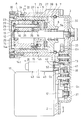
図3乃至図5に示すように、ロック機構40は、二次減速ギヤ列G2における出力側の中間ギヤ33の側面に複数の係止部としての係止孔41を同一円上に等間隔に設け、その複数の係止孔41のピッチ円上の一点に対して進退可能に設けられたロックピン42をリニアソレノイド43により進退させ、係止孔41に対するロックピン42の係合によって中間ギヤ33をロックするようにしている。
As shown in FIGS. 3 to 5, the
ここで、リニアソレノイド43は、テールキャップ45によってテール側の開口が閉塞され、ヘッドキャップ46によってヘッド側の開口が閉塞された円筒状のケース44を有し、そのケース44の内側にコイル47を組込み、そのコイル47の内径面を支持する円筒状のボビン48の内側にプランジャ49をスライド自在に組み込んでいる。
Here, the
また、ケース44内にヘッドキャップ46と軸方向で対向する磁気吸引コア50を組込み、その磁気吸引コア50とヘッドキャップ46のそれぞれにピン孔51、52を同軸上に形成し、そのピン孔51、52内にプランジャ49と別部品からなるロックピン42を挿入して、ロックピン42を軸方向の二箇所でスライド自在に支持案内している。
In addition, a
さらに、ヘッドキャップ46と磁気吸引コア50の対向面間にスプリング収容空間53を形成し、そのスプリング収容空間53内に組み込まれたリターンスプリング54によりロックピン42の外周に取付けた止め輪55を押圧して、ロックピン42およびプランジャ49を係合解除位置に向けて付勢している。
Further, a spring accommodating space 53 is formed between the facing surfaces of the
上記の構成からなるリニアソレノイド43とロックピン42の組立てユニットUは、ハウジング1と電動モータ11間に配置されてベースプレート2に取付けられる。この場合、ベースプレート2に挿入孔56を形成し、その挿入孔56にヘッドキャップ46の先端部を挿入し、そのヘッドキャップ46の外周に設けられた取付片46aをベースプレート2にねじ止めしている。
The assembly unit U of the
ここで、コイル47を支持するボビン48は、樹脂あるいは銅によって形成されている。また、プランジャ49および磁気吸引コア50のそれぞれはコイル47との間で磁気回路を形成するため、強磁性体で形成している。強磁性体として低炭素鋼を採用しているが、これに限定されるものではない。
Here, the
磁気吸引コア50は、ボビン48内に挿入される筒部50aを後端部に有し、その筒部50aの内周に形成されたテーパ孔50bに対してプランジャ49の先端部に形成されたテーパ軸部49aが嵌合可能とされている。
The
一方、ロックピン42およびヘッドキャップ46は、磁気の漏洩を防止するため、非磁性体で形成している。ここで、ロックピン42においては非磁性体としてのステンレス鋼で形成し、そのロックピン42を窒化あるいは軟窒化による表面処理によって耐摩耗性の向上を図るようにしている。なお、窒化あるいは軟窒化による表面処理に代えて、メッキ処理を施すようにしてもよい。
On the other hand, the
図4および図5に示すように、中間ギヤ33に形成された係止孔41の周方向で対向する端面の一方は、ロックピン42を後退動する方向に案内するテーパ面41aとされている。
As shown in FIGS. 4 and 5, one of the end faces facing the circumferential direction of the locking
実施の形態で示す電動式直動アクチュエータAは上記の構造からなり、図6は、その電動式直動アクチュエータAを採用した電動式ブレーキ装置Bを示す。この電動式ブレーキ装置Bにおいては、図示省略した車輪と共に回転するディスクロータ60の外周囲にキャリパ61を配置し、そのキャリパ61の一端部にディスクロータ60のアウタ側面の外周部と軸方向で対向する爪部62を設け、その爪部62にアウタ側ブレーキパッド63を取り付けている。
The electric linear actuator A shown in the embodiment has the above structure, and FIG. 6 shows an electric brake device B that employs the electric linear actuator A. In this electric brake device B, a
また、キャリパ61の他端部に電動式直動アクチュエータAのハウジングを一体に設けて、外輪部材4をディスクロータ60のインナ側面の外周部に軸方向で対向配置し、その外輪部材4の先端部にインナ側ブレーキパッド64を取り付けている。
In addition, the housing of the electric linear actuator A is integrally provided at the other end portion of the
ここで、キャリパ61は、ナックル等の静止部材に支持された図示省略したホルダにより支持されて、ディスクロータ60の軸方向に移動自在とされている。
Here, the
図6に示すような電動式ブレーキ装置Bへの電動式直動アクチュエータAの使用状態において、図1に示す電動モータ11を駆動すると、その電動モータ11のロータ軸12の回転がギヤ減速機構13により減速されて回転軸10に伝達される。
When the
回転軸10の外径面には、複数の遊星ローラ24のそれぞれ外径面が弾性接触しているため、上記回転軸10の回転により遊星ローラ24が回転軸10との接触摩擦により、自転しつつ公転する。
Since the outer diameter surfaces of the plurality of
このとき、遊星ローラ24の外径面に形成された螺旋溝25は外輪部材4の内径面に設けられた螺旋突条5に噛合しているため、その螺旋溝25と螺旋突条5の係合によって、外輪部材4が軸方向に移動し、その外輪部材4に連結一体化されたインナ側ブレーキパッド64がディスクロータ60に当接し、そのディスクロータ60を軸方向に押圧し始める。その押圧力の反力により爪部62に取付けられたアウタ側ブレーキパッド63がディスクロータ60に接近する方向に向けてキャリパ61が移動し、アウタ側ブレーキパッド63がディスクロータ60に当接して、そのアウタ側ブレーキパッド63がインナ側ブレーキパッド64とでディスクロータ60の外周部を軸方向両側から強く挟持し、ディスクロータ60に制動力が負荷される。
At this time, since the
駐車に際しては、上記のように、アウタ側ブレーキパッド63とインナ側ブレーキパッド64とがディスクロータ60を挟持する制動力の付与状態において、リニアソレノイド43のコイル47に通電する。その通電により、コイル47とプランジャ49および磁気吸引コア50の相互間で磁気回路が形成され、磁気吸引コア50からプランジャ49に付与される磁気吸引力によりプランジャ49が磁気吸引コア50に向けて移動して、その磁気吸引コア50に吸着される。
When parking, as described above, the outer
このとき、プランジャ49はロックピン42を押圧するため、ロックピン42は中間ギヤ33の側面に向けて前進する。ロックピン42の前進時、そのロックピン42に対して複数の係止孔41の一つが対向する状態にあると、図5に示すように、係止孔41にロックピン42が係合し、その係合によって中間ギヤ33がロックされる。この時、電動モータ11のロータ軸12もロックされることになるため、電動モータ11に対する通電を遮断しておくことができ、電気エネルギの無駄な消費を抑制することができる。
At this time, since the
ここで、ロックピン42の前進時、そのロックピン42と係止孔41との間に位相のずれがあると、係止孔41にロックピン42を係合させることができない。この場合、ロックピン42を前進させた状態で電動モータ11の駆動により、中間ギヤ33を制動方向(図4の矢印で示す方向)に回転させ、係止孔41をロックピン42と対向する位置まで中間ギヤ33を回転させて、係止孔41にロックピン42を係合させる。
Here, when the
上記のような係止孔41とロックピン42の係合による中間ギヤ33のロック状態、つまり、電動モータ11のロータ軸12のロック状態では、ディスクロータ60からの反力によりギヤ減速機構13のそれぞれのギヤに制動解除方向への回転力が負荷されるため、ロックピン42に傾動させるようなモーメント荷重が負荷される。
In the locked state of the
このとき、ロックピン42は、磁気吸引コア50に形成されたピン孔51とヘッドキャップ46に形成されたピン孔52のそれぞれによって軸方向の二箇所がスライド自在に支持されているため、ギヤ33からロックピン42に負荷されるモーメント荷重は磁気吸引コア50のピン孔51とヘッドキャップ46のピン孔52のそれぞれで分散して受けられることになり、ピン孔51、52の内径面を損傷させるようなことはない。
At this time, since the
ここで、ピン孔51、52とロックピン42の相互間にはロックピン42をスライド自在とするために微小な間隙が設けられている。このため、中間ギヤ33からロックピン42に負荷されるモーメント荷重により、ロックピン42は間隙の範囲内で傾動する。
Here, a minute gap is provided between the pin holes 51 and 52 and the
このとき、ロックピン42がプランジャ49と一体化されたものであると、ロックピン42と共にプランジャ49に傾きが生じ、プランジャ49の後端部での径方向への変位量は大きく、強度の弱いボビン48の内径面に大きなモーメント荷重が作用して、その内径面を損傷させることになる。
At this time, if the
しかし、実施の形態においては、ロックピン42をプランジャ49と別部品としているため、ロックピン42が傾動しても、プランジャ49は傾くことはなく、ボビン48の内径面を損傷させるようなことはない。
However, in the embodiment, since the
また、ロックピン42は、非磁性材料としてのステンレス鋼により形成しているため、コイル47の通電によって、そのコイル47、プランジャ49および磁気吸引コア50で形成される磁気回路の磁気がロックピン42に漏洩することはない。このため、プランジャ49に対する磁気吸引力の低下がなく、コイル47に対する通電によってロックピン42を中間ギヤ33に向けて確実に前進動させることができ、信頼性の高いロック動作を得ることができる。
Further, since the
図3に示すように、ヘッドキャップ46と磁気吸引コア50の対向面間にリターンスプリング54を収容するスプリング収容空間53を設けることにより、ヘッドキャップ46のピン孔52に侵入するギヤ潤滑用グリースをそのスプリング収容空間53で貯留することができるため、プランジャ49とコイル47を支持するボビン48の対向部間に形成されるクリアランスへのギヤ潤滑用グリースの侵入を防止することができる。このため、ギヤ潤滑用グリースによってプランジャ49のスライドが阻害されるのを防止することができる。
As shown in FIG. 3, by providing a spring accommodating space 53 for accommodating the
ここで、電動モータ11におけるロータ軸12のロック解除に際しては、コイル47に対する通電を解除し、電動モータ11を駆動して、中間ギヤ33を図5に示す制動方向に回転させ、ロックピン42に対する係止孔41の一側面の係合を解除し、係止孔41の他側のテーパ面41aがロックピン42の先端部を押圧する作用又はリターンスプリング54の押圧作用によってロックピン42を係止孔41から抜け出す係止解除位置まで後退動させる。
Here, when the lock of the
このとき、プランジャ49はテールキャップ45に衝撃的に当接して打撃音を発生させることになる。その打撃音の発生を抑制するため、図3では、プランジャ49の後端面にリング状の弾性部材57を取付け、その弾性部材57の弾性変形によりテールキャップ45に対する当接時の衝撃力を吸収するようにしている。
At this time, the
図1に示す電動式直動アクチュエータにおいては、回転軸10の回転運動を直線運動に変換する回転・直動変換機構として、その回転軸10の外径面とハウジング1の内径面間に遊星ローラ24を組込み、その遊星ローラ24の外径面に外輪部材4の内径面に設けられた螺旋突条5に噛合する螺旋溝25または円周溝を形成したものを示したが、回転・直動変換機構はこれに限定されるものではない。
In the electric linear actuator shown in FIG. 1, a planetary roller is provided between the outer diameter surface of the
例えば、特許文献3の図10に示されているように、回転軸の外径面に螺旋突条を設け、その回転軸の外径面とハウジングの内径面間に組み込まれた複数の遊星ローラの外径面に螺旋突条と同一ピッチで複数の円周溝を形成し、上記回転軸の回転により、螺旋突条と円周溝の係合によって遊星ローラを自転させつつ公転させて、その遊星ローラを軸方向に移動させるようにしてもよい。
For example, as shown in FIG. 10 of
4 外輪部材(スライド部材)
11 電動モータ
12 ロータ軸
13 ギヤ減速機構
33 中間ギヤ
40 ロック機構
41 係止孔(係止部)
42 ロックピン
43 リニアソレノイド
44 ケース
46 ヘッドキャップ
47 コイル
49 プランジャ
50 磁気吸引コア
51 ピン孔
52 ピン孔
53 スプリング収容空間
54 リターンスプリング
60 ディスクロータ
4 Outer ring member (slide member)
11
42
Claims (6)
前記リニアソレノイドにおけるプランジャと前記ロックピンとを別部品として端面が軸方向で対向する同軸上の配置とし、そのロックピンを非磁性材料で形成し、前記ロックピンを前記プランジャに対して傾動可能となるようにスライド自在に案内支持し、前記ロックピンにリターンスプリングの弾性力を付与してロックピンと共にプランジャを後退動させるようにしたことを特徴とする電動式直動アクチュエータ。 An electric motor, a gear reduction mechanism that decelerates and outputs the rotation of the rotor shaft of the electric motor, a slide member that is movable in the axial direction along the axis of the output gear of the gear reduction mechanism, and the output gear A rotation / linear motion conversion mechanism that converts a rotary motion into a linear motion and transmits the linear motion to the slide member; and a lock mechanism that can lock and unlock the rotation of the rotor shaft of the electric motor. A plurality of engaging portions provided in the circumferential direction of one of the plurality of gears forming the gear reduction mechanism, and the engaging portions are provided so as to be capable of moving forward and backward with respect to the engaging portions. In an electric linear actuator that includes a lock pin that engages with and locks the gear, and a linear solenoid that advances and retracts the lock pin.
With the plunger and the lock pin in the linear solenoid as separate parts, the end faces are arranged coaxially with each other facing in the axial direction, the lock pin is made of a nonmagnetic material, and the lock pin can be tilted with respect to the plunger. The electric linear actuator is characterized in that it is slidably guided and supported, and an elastic force of a return spring is applied to the lock pin so that the plunger is moved backward together with the lock pin.
前記電動式直動アクチュエータが請求項1乃至5のいずれか1項に記載の電動式直動アクチュエータからなり、その電動式直動アクチュエータのスライド部材に前記ブレーキパッドを連結したことを特徴とする電動式ブレーキ装置。 In the electric brake device in which the brake pad is linearly driven by the electric linear actuator, the disc rotor is pressed with the brake pad, and the braking force is applied to the disc rotor.
The electric linear actuator comprises the electric linear actuator according to any one of claims 1 to 5, wherein the brake pad is connected to a slide member of the electric linear actuator. Brake device.
Priority Applications (5)
| Application Number | Priority Date | Filing Date | Title |
|---|---|---|---|
| JP2013089061A JP6190146B2 (en) | 2013-04-22 | 2013-04-22 | Electric linear actuator and electric brake device |
| CN201480022964.4A CN105190080B (en) | 2013-04-22 | 2014-04-17 | Electric linear actuator and electric brake device |
| EP14788301.1A EP2990682B1 (en) | 2013-04-22 | 2014-04-17 | Electric direct-acting actuator and electric braking device |
| PCT/JP2014/060903 WO2014175153A1 (en) | 2013-04-22 | 2014-04-17 | Electric direct-acting actuator and electric braking device |
| US14/785,662 US9624994B2 (en) | 2013-04-22 | 2014-04-17 | Electric linear motion actuator and electric brake system |
Applications Claiming Priority (1)
| Application Number | Priority Date | Filing Date | Title |
|---|---|---|---|
| JP2013089061A JP6190146B2 (en) | 2013-04-22 | 2013-04-22 | Electric linear actuator and electric brake device |
Publications (2)
| Publication Number | Publication Date |
|---|---|
| JP2014211222A JP2014211222A (en) | 2014-11-13 |
| JP6190146B2 true JP6190146B2 (en) | 2017-08-30 |
Family
ID=51791732
Family Applications (1)
| Application Number | Title | Priority Date | Filing Date |
|---|---|---|---|
| JP2013089061A Active JP6190146B2 (en) | 2013-04-22 | 2013-04-22 | Electric linear actuator and electric brake device |
Country Status (5)
| Country | Link |
|---|---|
| US (1) | US9624994B2 (en) |
| EP (1) | EP2990682B1 (en) |
| JP (1) | JP6190146B2 (en) |
| CN (1) | CN105190080B (en) |
| WO (1) | WO2014175153A1 (en) |
Families Citing this family (16)
| Publication number | Priority date | Publication date | Assignee | Title |
|---|---|---|---|---|
| US9587692B2 (en) | 2015-04-01 | 2017-03-07 | Akebono Brake Industry Co., Ltd | Differential for a parking brake assembly |
| JP6679380B2 (en) * | 2016-03-30 | 2020-04-15 | Ntn株式会社 | Electric actuator |
| US10267371B2 (en) | 2016-05-16 | 2019-04-23 | Akebono Brake Industry Co., Ltd | Devices for operating a parking brake |
| JP6801998B2 (en) * | 2016-08-04 | 2020-12-16 | 株式会社Subaru | Wheel structure |
| JP6898082B2 (en) * | 2016-11-25 | 2021-07-07 | 平田機工株式会社 | Transport method and transport device |
| JP6457572B2 (en) * | 2017-03-13 | 2019-01-23 | ファナック株式会社 | Injection device |
| US10428888B2 (en) | 2017-10-30 | 2019-10-01 | Akebono Brake Industry Co., Ltd. | Brake system |
| CN110094442B (en) * | 2018-01-31 | 2020-09-25 | 上海汇众汽车制造有限公司 | Electric execution unit and electronic brake comprising same |
| JP7063195B2 (en) * | 2018-08-24 | 2022-05-09 | トヨタ自動車株式会社 | Friction brake, in-vehicle device |
| US11377083B2 (en) * | 2018-11-15 | 2022-07-05 | Mando Corporation | Electromechanical actuator package for actuating brake assembly |
| CN109624954A (en) * | 2018-12-06 | 2019-04-16 | 北京长城华冠汽车科技股份有限公司 | A kind of braking system and automobile |
| GB2579805B (en) * | 2018-12-14 | 2020-12-23 | Continental Automotive Romania Srl | Hydraulic electronic control unit |
| CN111628609B (en) * | 2019-02-28 | 2022-10-04 | 日本电产株式会社 | Brake device and power assembly |
| US11339842B2 (en) | 2019-03-26 | 2022-05-24 | Akebono Brake Industry Co., Ltd. | Brake system with torque distributing assembly |
| JP2020158044A (en) * | 2019-03-28 | 2020-10-01 | Ntn株式会社 | Electrically-driven actuator and electric brake device |
| US11628944B2 (en) | 2021-04-05 | 2023-04-18 | Honeywell International Inc. | Actuator for use in a piston engine powered aircraft actuation control system |
Family Cites Families (20)
| Publication number | Priority date | Publication date | Assignee | Title |
|---|---|---|---|---|
| GB1277986A (en) * | 1970-03-20 | 1972-06-14 | Westinghouse Electric Corp | Improvements in or relating to an electrohydraulic brake control system |
| DE3148503C2 (en) * | 1981-12-08 | 1983-11-17 | Siemens AG, 1000 Berlin und 8000 München | Plunging armature magnet system with a composite armature with high propulsive force |
| USRE32860E (en) * | 1983-12-23 | 1989-02-07 | G. W. Lisk Company, Inc. | Solenoid construction and method for making the same |
| JPS6226002U (en) * | 1985-07-31 | 1987-02-17 | ||
| JPH0626002A (en) | 1992-07-09 | 1994-02-01 | Atom Chem Paint Co Ltd | Elastic paving body and forming method therefor |
| DE4412621A1 (en) * | 1994-04-13 | 1995-10-19 | Bosch Gmbh Robert | Proportional solenoid for use in vehicle suspension dampers |
| DE19732168C2 (en) * | 1997-07-25 | 2003-06-18 | Lucas Ind Plc | Hydraulic vehicle brake with locking device and method for operating the same |
| SE0104279D0 (en) * | 2001-12-18 | 2001-12-18 | Haldex Brake Prod Ab | A parking brake arrangement in an electrically operated brake |
| JP4316955B2 (en) * | 2003-08-11 | 2009-08-19 | イーグル工業株式会社 | Capacity control valve |
| US7325564B2 (en) | 2004-03-24 | 2008-02-05 | Keihin Corporation | Linear solenoid valve |
| JP4515127B2 (en) * | 2004-03-26 | 2010-07-28 | 株式会社ケーヒン | Linear solenoid valve |
| JP2008286386A (en) * | 2007-04-16 | 2008-11-27 | Ntn Corp | Electric direct-acting actuator and electric brake device |
| JP5243018B2 (en) * | 2007-12-27 | 2013-07-24 | Ntn株式会社 | Electric linear actuator |
| DE102008010649A1 (en) * | 2008-02-22 | 2009-08-27 | Schaeffler Kg | Electromagnetic actuator unit for regulating central valve of internal combustion engine of motor vehicle, has armature and coil movable together, where armature is arranged in direction of axial adjustment produced by fields of coil on pin |
| JP5257764B2 (en) | 2008-09-11 | 2013-08-07 | Ntn株式会社 | Electric linear actuator and electric brake device |
| JP5282998B2 (en) | 2008-10-07 | 2013-09-04 | Ntn株式会社 | Electric linear actuator and electric brake device |
| JP5543766B2 (en) * | 2009-12-08 | 2014-07-09 | 株式会社東芝 | Electromagnetic actuator |
| JP5829394B2 (en) * | 2010-10-20 | 2015-12-09 | Ntn株式会社 | Electric linear actuator and electric disc brake device |
| WO2014203898A1 (en) * | 2013-06-17 | 2014-12-24 | アイシン・エィ・ダブリュ株式会社 | Parking device |
| US9381799B2 (en) * | 2014-02-25 | 2016-07-05 | GM Global Technology Operations LLC | Hybrid vehicle internal combustion engine |
-
2013
- 2013-04-22 JP JP2013089061A patent/JP6190146B2/en active Active
-
2014
- 2014-04-17 WO PCT/JP2014/060903 patent/WO2014175153A1/en active Application Filing
- 2014-04-17 US US14/785,662 patent/US9624994B2/en active Active
- 2014-04-17 EP EP14788301.1A patent/EP2990682B1/en active Active
- 2014-04-17 CN CN201480022964.4A patent/CN105190080B/en active Active
Also Published As
| Publication number | Publication date |
|---|---|
| EP2990682B1 (en) | 2017-06-07 |
| JP2014211222A (en) | 2014-11-13 |
| CN105190080A (en) | 2015-12-23 |
| EP2990682A4 (en) | 2016-07-27 |
| US9624994B2 (en) | 2017-04-18 |
| US20160076607A1 (en) | 2016-03-17 |
| CN105190080B (en) | 2017-12-15 |
| EP2990682A1 (en) | 2016-03-02 |
| WO2014175153A1 (en) | 2014-10-30 |
Similar Documents
| Publication | Publication Date | Title |
|---|---|---|
| JP6190146B2 (en) | Electric linear actuator and electric brake device | |
| JP6335443B2 (en) | Electric brake device | |
| JP6468851B2 (en) | Electric linear actuator and electric brake device | |
| JP5658046B2 (en) | Rotation transmission device | |
| EP1456564B1 (en) | Screw actuator with locking mechanism | |
| WO2014185229A1 (en) | Electric linear motion actuator and electric brake device | |
| JP2013160335A (en) | Electric direct-acting actuator and electric braking device | |
| JP2012057681A (en) | Electric linear actuator and electric disk brake device | |
| JP2015161388A (en) | Electrical-driven linear motion actuator and electrical-driven brake device | |
| WO2008154830A1 (en) | Tri-state overrunning clutch | |
| JP2011169381A (en) | Electromagnetic coupling device | |
| JP2015086886A (en) | Electrically-driven linear motion actuator and electric brake device | |
| KR101221123B1 (en) | Electric brake motor | |
| JP5946399B2 (en) | Electric disc brake device | |
| JP2020058215A (en) | Electric actuator | |
| US9163680B2 (en) | Powerless brake | |
| JP2006170416A (en) | Rotation transmitting device | |
| JP2005076718A (en) | Rotation transmitting device | |
| JP2020158044A (en) | Electrically-driven actuator and electric brake device | |
| JP2019152317A (en) | Brake device | |
| JP2006097845A (en) | Disc brake | |
| JP2019113109A (en) | Electric actuator | |
| JP2005124350A (en) | Actuator | |
| JP2009162326A (en) | Power transmission device |
Legal Events
| Date | Code | Title | Description |
|---|---|---|---|
| A621 | Written request for application examination |
Free format text: JAPANESE INTERMEDIATE CODE: A621 Effective date: 20160328 |
|
| A131 | Notification of reasons for refusal |
Free format text: JAPANESE INTERMEDIATE CODE: A131 Effective date: 20161206 |
|
| A521 | Request for written amendment filed |
Free format text: JAPANESE INTERMEDIATE CODE: A523 Effective date: 20170203 |
|
| TRDD | Decision of grant or rejection written | ||
| A01 | Written decision to grant a patent or to grant a registration (utility model) |
Free format text: JAPANESE INTERMEDIATE CODE: A01 Effective date: 20170711 |
|
| A61 | First payment of annual fees (during grant procedure) |
Free format text: JAPANESE INTERMEDIATE CODE: A61 Effective date: 20170804 |
|
| R150 | Certificate of patent or registration of utility model |
Ref document number: 6190146 Country of ref document: JP Free format text: JAPANESE INTERMEDIATE CODE: R150 |
|
| R250 | Receipt of annual fees |
Free format text: JAPANESE INTERMEDIATE CODE: R250 |
|
| R250 | Receipt of annual fees |
Free format text: JAPANESE INTERMEDIATE CODE: R250 |
|
| R250 | Receipt of annual fees |
Free format text: JAPANESE INTERMEDIATE CODE: R250 |
|
| R250 | Receipt of annual fees |
Free format text: JAPANESE INTERMEDIATE CODE: R250 |