JP2010023618A - Load receiving platform elevator - Google Patents

Load receiving platform elevator Download PDF

Info

Publication number
JP2010023618A
JP2010023618A JP2008186149A JP2008186149A JP2010023618A JP 2010023618 A JP2010023618 A JP 2010023618A JP 2008186149 A JP2008186149 A JP 2008186149A JP 2008186149 A JP2008186149 A JP 2008186149A JP 2010023618 A JP2010023618 A JP 2010023618A
Authority
JP
Japan
Prior art keywords
load receiving
platform
receiving platform
load
vehicle
Prior art date
Legal status (The legal status is an assumption and is not a legal conclusion. Google has not performed a legal analysis and makes no representation as to the accuracy of the status listed.)
Granted
Application number
JP2008186149A
Other languages
Japanese (ja)
Other versions
JP5427376B2 (en
Inventor
Yasushi Maeda
泰志 前田
Current Assignee (The listed assignees may be inaccurate. Google has not performed a legal analysis and makes no representation or warranty as to the accuracy of the list.)
Kyokuto Kaihatsu Kogyo Co Ltd
Original Assignee
Kyokuto Kaihatsu Kogyo Co Ltd
Priority date (The priority date is an assumption and is not a legal conclusion. Google has not performed a legal analysis and makes no representation as to the accuracy of the date listed.)
Filing date
Publication date
Application filed by Kyokuto Kaihatsu Kogyo Co Ltd filed Critical Kyokuto Kaihatsu Kogyo Co Ltd
Priority to JP2008186149A priority Critical patent/JP5427376B2/en
Publication of JP2010023618A publication Critical patent/JP2010023618A/en
Application granted granted Critical
Publication of JP5427376B2 publication Critical patent/JP5427376B2/en
Active legal-status Critical Current
Anticipated expiration legal-status Critical

Links

Images

Abstract

<P>PROBLEM TO BE SOLVED: To provide a load receiving platform elevator capable of simplifying a configuration for preventing a load receiving platform in a stored state from falling. <P>SOLUTION: The load receiving platform elevator 1 is mounted on a vehicle C in which a flapper 10 that rises when a vehicle travels is provided on a loading platform 11. The load receiving platform elevator includes: a load receiving platform 2 for loading goods; and a lift cylinder 5 for lifting the load receiving platform 2 from the ground to an upper position on the loading platform 11 with the supply of an operation oil. The load receiving platform 2 is mounted with a hinge part 8 to change its posture so that it takes a horizontal posture during unloading operation of goods, and takes a rising posture at the upper position when the vehicle travels. The load receiving platform 2 includes an abutting part 15 which can abut on the rising flapper 10 when the load receiving platform 2 in the rising posture at the upper position when the vehicle travels is about to fall. <P>COPYRIGHT: (C)2010,JPO&INPIT

Description

本発明は、車両に取り付けられ荷物の積み降ろしに利用される荷受台昇降装置に関する。   The present invention relates to a load receiving table lifting device that is attached to a vehicle and used for loading and unloading loads.

貨物車両に取り付けられ、荷物の積み降ろしに利用される荷受台昇降装置として、例えば特許文献1に記載のものがある。この荷受台昇降装置は、荷台に固定されたベースブラケットと、荷物を載せる荷受台と、荷受台をベースブラケットに取り付けていると共に上下回動可能であるアームと、アームを上下回動させる油圧シリンダと、油圧ユニットとを備えており、油圧ユニットから作動油が供給されることで油圧シリンダが収縮し、荷受台を荷台上に上昇させることができる。
また、荷受台は、その基部の回動中心回りに回動可能であり、荷物の積み降ろしを行なわない車両走行時では、荷受台を荷台上へ上昇させ、前記回動中心回りに荷受台を回動させることで当該荷受台を起立させた状態とする。これにより、荷受台昇降装置を荷台上でコンパクトに格納することができる。
For example, Patent Document 1 discloses a load receiving table lifting device that is attached to a cargo vehicle and used for loading and unloading loads. This load receiving device elevating device includes a base bracket fixed to the load receiving plate, a load receiving plate on which a load is placed, an arm that attaches the load receiving plate to the base bracket and can be rotated up and down, and a hydraulic cylinder that rotates the arm up and down. And a hydraulic unit. When hydraulic oil is supplied from the hydraulic unit, the hydraulic cylinder contracts, and the load receiving platform can be raised on the loading platform.
In addition, the cargo cradle can be rotated around the center of rotation of the base, and when the vehicle is traveling without loading and unloading, the cargo cradle is raised on the platform and the cradle is moved around the rotation center. It is set as the state which raised the said receiving stand by rotating. Thereby, the load receiving platform lifting device can be compactly stored on the load receiving platform.

このような荷受台昇降装置では、荷受台が不要である場合、油圧シリンダに作動油を供給することで油圧シリンダを収縮させて荷受台を荷台上に上昇させ、当該荷受台を起立させた状態として格納している。しかし、荷台上にある荷受台の自重によって油圧シリンダに伸長方向の荷重が作用し、例えば油圧ユニット内の弁において僅かな作動油の漏れが生じると、油圧シリンダ内から作動油が抜け出ることがあり、これにより、荷受台が勝手に下降するおそれがある。
そこで、起立状態にある荷受台を荷台上で保持するために、専用のロック装置が必要とされている(特許文献1及び特許文献2)。
特許文献1に記載の荷受台昇降装置では、ロック装置として、荷受台に止め具が設けられ、アームにブラケットが設けられている。荷受台を起立させた状態で、止め具とブラケットとを係合させることにより、荷受台を格納状態でロックすることができる。
また、特許文献2に記載の荷受台昇降装置は、ロック装置として、ロック爪、このロック爪を回動させる油圧シリンダを備えており、油圧シリンダの伸縮動作によってロック爪を回動させ、当該ロック爪を荷受台に係合させ、荷受台を格納状態でロックしている。
In such a loading platform lifting device, when the loading platform is not required, the hydraulic cylinder is contracted by supplying hydraulic oil to the hydraulic cylinder, the loading platform is raised on the loading platform, and the loading platform is raised. As stored. However, if the load in the extension direction acts on the hydraulic cylinder due to its own weight on the loading platform, for example, if a slight amount of hydraulic oil leaks in the valve in the hydraulic unit, the hydraulic oil may escape from the hydraulic cylinder. As a result, there is a risk that the cargo receiving platform will be lowered without permission.
Therefore, a dedicated locking device is required in order to hold the standing cradle on the cradle (Patent Document 1 and Patent Document 2).
In the load receiving platform lifting device described in Patent Document 1, as a locking device, a stop is provided on the load receiving stand, and a bracket is provided on the arm. By engaging the stopper and the bracket while the load receiving stand is raised, the load receiving stand can be locked in the retracted state.
In addition, the load receiving platform lifting device described in Patent Document 2 includes a lock claw and a hydraulic cylinder that rotates the lock claw as a lock device. The claw is engaged with the load receiving table, and the load receiving table is locked in the retracted state.

実公昭63−44272号公報(第2図参照)Japanese Utility Model Publication No. 63-44272 (see FIG. 2) 実公昭61−16177号公報(第3図参照)Japanese Utility Model Publication No. 61-16177 (see FIG. 3)

特許文献1の装置では、荷受台側とアーム側との双方にロック装置用の部材が設けられている。また、特許文献2の装置では、荷受台を昇降させる昇降用の油圧シリンダの他に、ロック爪を回動させる油圧シリンダが更に必要である。このように、特許文献1及び特許文献2のような従来の荷受台昇降装置では、格納状態にある荷受台の降下を防止するための構成が複雑化し、装置が高価なものとなってしまう。   In the device of Patent Document 1, members for a lock device are provided on both the cargo receiving side and the arm side. Moreover, in the apparatus of patent document 2, in addition to the lifting and lowering hydraulic cylinder that lifts and lowers the load receiving table, a hydraulic cylinder that rotates the lock claw is further required. As described above, in the conventional load receiving table lifting apparatus such as Patent Document 1 and Patent Document 2, the configuration for preventing the load receiving table in the retracted state from being lowered is complicated, and the apparatus becomes expensive.

そこで、本発明は前記問題点に鑑みてなされたものであり、格納状態にある荷受台の降下を防止するための構成を簡素化することができる荷受台昇降装置を提供することを目的とする。   Therefore, the present invention has been made in view of the above problems, and an object of the present invention is to provide a load receiving table lifting device capable of simplifying the configuration for preventing the load receiving table from being lowered in the retracted state. .

本発明の荷受台昇降装置は、車両走行時に起立した状態とする開閉扉が荷台上に設けられている車両の当該荷台上に取り付けられ、地上と前記荷台上との間で荷物の積み降ろしを行なう荷受台昇降装置において、荷物を載せる荷受台を有した上下動する昇降部と、作動流体が供給されることにより前記昇降部を上昇させ前記荷受台を地上から前記荷台上の上位置へと上げる流体アクチュエータを有している昇降駆動機構とを備え、前記昇降部は、荷物の積み降ろし作業時に水平姿勢となり車両走行時に前記上位置で起立姿勢となるように前記荷受台が姿勢変化可能に取り付けられている取付部と、車両走行時に前記上位置で起立姿勢にある前記荷受台が降下し始めると又は降下しようとすると、起立している前記開閉扉に当接して当該荷受台の降下を妨げる当接部とを有している。   The load receiving platform elevating device of the present invention is mounted on the load platform of the vehicle provided with an opening / closing door provided on the load platform to stand up when the vehicle travels, and loads and unloads the load between the ground and the load platform. In the loading platform lifting apparatus to be performed, a vertically moving lifting unit having a loading platform on which a load is placed, and the lifting unit is lifted by supplying a working fluid to move the loading platform from the ground to an upper position on the loading platform. An elevating drive mechanism having a fluid actuator to be raised, and the elevating part is capable of changing its attitude so that the elevating part is in a horizontal position during loading and unloading work and is in a standing position in the upper position when the vehicle is traveling When the mounted portion and the load receiving stand in the upright position at the upper position when the vehicle is running start to descend or try to descend, the load receiving stand comes into contact with the openable door And a contact portion that prevents the descent.

本発明によれば、流体アクチュエータに作動流体が供給されると、昇降部を上昇させ荷受台を荷台上の上位置へと上げる構成であるため、車両走行時において、流体アクチュエータから作動流体が抜け出ると、昇降部が自重によって下降し上位置にある荷受台は下降するおそれがあるが、このような場合であっても、車両走行時に上位置で起立姿勢にある荷受台が降下し始めると又は降下しようとすると、昇降部の当接部が、荷台で起立している開閉扉に当接して当該荷受台の降下を妨げるので、昇降部が地上へ降下してしまうのを防ぐことができる。このように、車両が既に備えている開閉扉が用いられて、格納状態にある荷受台の降下を規制することができるので、格納状態にある荷受台の降下を防止するための部材が少なくなり、構成の簡素化が可能となる。   According to the present invention, when the working fluid is supplied to the fluid actuator, the elevating unit is raised and the load receiving platform is raised to the upper position on the loading platform. Therefore, when the vehicle travels, the working fluid comes out of the fluid actuator. In such a case, even if the lifting platform is lowered by its own weight and the cargo cradle in the up position when the vehicle is running, If it is going to descend, the abutting part of the elevating part abuts on the open / close door standing on the loading platform and prevents the loading platform from descending, so that the lifting unit can be prevented from descending to the ground. In this way, since the opening / closing door already provided in the vehicle is used and the descent of the receiving platform in the retracted state can be regulated, the number of members for preventing the descending of the receiving platform in the retracted state is reduced. The configuration can be simplified.

また、前記当接部は、前記荷受台の裏面に設けられ、水平姿勢にある当該荷受台が地上に降りた際に地上に接触する接地部であるのが好ましい。
本発明によれば、荷受台の裏面に設けられ荷物の積み降ろしの際に地上に接触する接地部が、車両走行時における荷受台の降下を防止する前記当接部として兼用されているので、部品点数の低減が図れる。
Moreover, it is preferable that the said contact part is a grounding part which is provided in the back surface of the said receiving cradle, and contacts the ground when the said receiving cradle in a horizontal posture gets down on the ground.
According to the present invention, the grounding portion that is provided on the back surface of the load receiving platform and contacts the ground when loading and unloading the load is also used as the abutting portion that prevents the load receiving platform from being lowered during vehicle travel. The number of parts can be reduced.

また、前記当接部は、前記昇降部に取り付けられた非金属製の緩衝部材によって構成されているのが好ましい。この構成によれば、開閉扉に対する当接部の接触による衝撃を緩和することができる。   Moreover, it is preferable that the said contact part is comprised by the non-metallic buffer member attached to the said raising / lowering part. According to this structure, the impact by contact of the contact part with respect to an opening / closing door can be relieved.

また、本発明の荷受台昇降装置は、前記開閉扉に取り付けられ前記当接部と接触する非金属製の緩衝部材を更に備えているのが好ましい。
この構成によれば、開閉扉に対する当接部の接触による衝撃を緩和することができる。
Moreover, it is preferable that the load receiving platform lifting apparatus of the present invention further includes a non-metallic buffer member that is attached to the opening / closing door and contacts the contact portion.
According to this structure, the impact by contact of the contact part with respect to an opening / closing door can be relieved.

本発明によれば、車両が既に備えている開閉扉が用いられて、格納状態にある荷受台の降下を規制することができるので、別途、荷受台の降下防止用として多くの部材が不要であり、構成の簡素化が可能となる。   According to the present invention, since the opening / closing door already provided in the vehicle is used and the descent of the load receiving table in the retracted state can be regulated, many members are not separately required for preventing the descent of the load receiving table. Yes, the configuration can be simplified.

以下、本発明の実施の形態を図面に基づいて説明する。
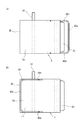
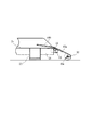
図1、図2、図3及び図4は、本発明の荷受台昇降装置の実施の一形態を示す側面図である。図5は図4に示した状態にある荷受台昇降装置の背面図である。この荷受台昇降装置1は、荷台11を備えた貨物車両Cの当該荷台11上に取り付けられ、地上と荷台11上との間で荷物の積み降ろしを行なうために利用されるものである。荷台11上の後端部には、車両走行時に起立した状態とする後部の煽戸(開閉扉)10が設けられている。また、図5において、荷台11上の車幅方向の側端部には、車両走行時に起立した状態とする側部の煽戸20が設けられている。
Hereinafter, embodiments of the present invention will be described with reference to the drawings.
1, FIG. 2, FIG. 3 and FIG. 4 are side views showing an embodiment of the load receiving platform lifting apparatus of the present invention. FIG. 5 is a rear view of the load receiving table lifting device in the state shown in FIG. The load receiving platform lifting / lowering device 1 is mounted on the loading platform 11 of the cargo vehicle C including the loading platform 11 and is used for loading and unloading loads between the ground and the loading platform 11. A rear side door (opening / closing door) 10 is provided at the rear end portion of the loading platform 11 so as to stand up when the vehicle is traveling. Further, in FIG. 5, a side door 20 is provided at a side end portion in the vehicle width direction on the loading platform 11 so as to stand in a standing state when the vehicle travels.

これら煽戸10,20それぞれは、荷台11の縁部に設けられたヒンジによって上下方向に回動して開閉可能となっていて、閉状態で荷台11の縁部から立ち上がった状態(図4と図5参照)となり、開状態で、荷台11の縁部から下方へ垂れ下がった状態となる(図1〜図3参照)。また、荷台11には、起立した煽戸10,20をその起立姿勢で固縛する固縛部(図示せず)が設けられている。固縛部は、使用者によって操作され、煽戸10,20を起立姿勢(閉状態)に拘束する固縛状態と、開状態可能とする解除状態とのいずれかに切り替えられる。なお、図5では、後部の煽戸10は開状態にある。煽戸10,20は、鋼板等によって製造されている。   Each of these doors 10 and 20 can be opened and closed by being pivoted in the vertical direction by a hinge provided at the edge of the loading platform 11, and standing up from the edge of the loading platform 11 in a closed state (see FIG. 4). 5), and in the open state, the bag 11 hangs downward from the edge of the loading platform 11 (see FIGS. 1 to 3). The loading platform 11 is provided with a securing portion (not shown) that secures the standing doors 10 and 20 in the standing posture. The lashing portion is operated by the user, and is switched between a lashing state in which the doors 10 and 20 are restrained in a standing posture (closed state) and a release state in which the sashing state is enabled. In FIG. 5, the rear door 10 is in an open state. The doors 10 and 20 are made of a steel plate or the like.

荷受台昇降装置1は荷物を載せる荷受台2を備えており、この荷受台2は、荷物を載せる載置面2aを表面に有する盤状の荷受台本体21を有している。図示している荷受台昇降装置1は、荷台11の上面11aの後端部に取り付けられており、荷受台2は、荷台11の後端部の上方の位置と、車両後方における接地位置との間を昇降する。車両前後方向が、図1〜図3の状態にある荷受台2の奥行き方向と一致しており、車幅方向(車両Cの左右方向)が、荷受台2の幅方向と一致している。   The load receiving platform lifting / lowering device 1 includes a load receiving stand 2 on which a load is placed. The load receiving stand 2 has a disk-shaped load receiving stand main body 21 having a placement surface 2a on which a load is placed. The illustrated loading platform lifting / lowering device 1 is attached to the rear end portion of the upper surface 11a of the loading platform 11, and the loading platform 2 has a position above the rear end portion of the loading platform 11 and a ground contact position behind the vehicle. Go up and down. The vehicle front-rear direction matches the depth direction of the load receiving platform 2 in the state of FIGS. 1 to 3, and the vehicle width direction (the left-right direction of the vehicle C) matches the width direction of the load receiving platform 2.

荷受台昇降装置1は、荷受台2の他に、荷台11の上面11aに取り付けられるベースブラケット(ベース部)3と、荷受台2を支持している支持体7と、ベースブラケット3と支持体7とを連結しているアーム体4と、伸縮するリフトシリンダ5と、このリフトシリンダ5を駆動するパワーユニット6とを備えている。ベースブラケット3、アーム体4及び支持体7は、荷台11の後部において、車幅方向の一方側の端部に設けられている(図5参照)。そして、荷受台2は車幅方向の中央寄りの位置に設けられている。   In addition to the load receiving platform 2, the load receiving platform lifting / lowering device 1 includes a base bracket (base portion) 3 attached to the upper surface 11 a of the load receiving platform 11, a support body 7 that supports the load receiving rack 2, a base bracket 3 and a support body. 7 is provided with an arm body 4 that is coupled to a lift cylinder 7, a lift cylinder 5 that expands and contracts, and a power unit 6 that drives the lift cylinder 5. The base bracket 3, the arm body 4, and the support body 7 are provided at the end of one side in the vehicle width direction at the rear part of the loading platform 11 (see FIG. 5). And the goods receiving stand 2 is provided in the position near the center of the vehicle width direction.

前記ベースブラケット3は、例えばボルト12により荷台11の上面11aの後部に着脱可能として取り付けられている。ボルト12によってベースブラケット3を荷台11に取り付けることから、荷受台昇降装置1の貨物車両Cへの取り付けが簡単であり、また、貨物車両C側において、ボルト孔を設ければよく大きな改造が不要である。
また、荷受台昇降装置1の不使用時では、ボルト12を外すことにより、ベースブラケット3を荷台11から取り外すことができる。これにより、荷受台昇降装置1を車両Cから取り外すことができる。荷受台昇降装置1を荷台11上に常設していると、その自重によって貨物車両Cの積載可能重量が小さくなったり、荷台11上の積み込み可能スペースが減少したりするが、取り外し構造とすることにより、これを防止することができる。これは、貨物車両Cが、積載可能重量が比較的小さく、荷台11上の積み込みスペースが比較的小さい軽トラックである場合に特に有効となる。
The base bracket 3 is detachably attached to the rear portion of the upper surface 11a of the loading platform 11 with bolts 12, for example. Since the base bracket 3 is attached to the loading platform 11 with the bolts 12, it is easy to attach the cargo receiving platform lifting / lowering device 1 to the freight vehicle C, and it is only necessary to provide a bolt hole on the freight vehicle C side, and no major modification is required. It is.
Further, when the load receiving platform lifting / lowering device 1 is not used, the base bracket 3 can be detached from the load holding platform 11 by removing the bolts 12. Thereby, the load receiving platform lifting / lowering device 1 can be detached from the vehicle C. If the loading platform lifting / lowering device 1 is permanently installed on the loading platform 11, the loadable weight of the cargo vehicle C is reduced by its own weight or the loadable space on the loading platform 11 is reduced. Therefore, this can be prevented. This is particularly effective when the cargo vehicle C is a light truck having a relatively small loadable weight and a relatively small loading space on the loading platform 11.

前記アーム体4は、第一アーム13と第二アーム14とを有しており、平行リンクを構成している。第一アーム13は、ベースブラケット3から一方向に延びている部材であり、第一アーム13の基部13aはベースブラケット3の上部に回動自在として取り付けられており、先部13bは支持体7(後述する側部支持フレーム7a)の上部に回動自在として取り付けられている。第二アーム14は、ベースブラケット3から第一アーム13に沿って延びている部材であり、第二アーム14の基部14aはベースブラケット3に回動自在として取り付けられており、先部14bは支持体7(側部支持フレーム7a)に回動自在として取り付けられている。   The arm body 4 has a first arm 13 and a second arm 14 and constitutes a parallel link. The first arm 13 is a member extending in one direction from the base bracket 3, the base portion 13 a of the first arm 13 is rotatably attached to the upper portion of the base bracket 3, and the tip portion 13 b is the support 7. It is rotatably attached to the upper part of a (side support frame 7a described later). The second arm 14 is a member extending from the base bracket 3 along the first arm 13, the base portion 14 a of the second arm 14 is rotatably attached to the base bracket 3, and the tip portion 14 b is supported. The body 7 (side support frame 7a) is rotatably attached.

そして、アーム体4は、ベースブラケット3から上方へ延びている起立位置(図1)と、車両後方でかつ地上へ向かう斜め下方に延びている後方位置(図3)との間を揺動することができる。このアーム体4によって、支持体7及び荷受台2は、荷台11後部の上方の上位置(図1)と車両後方において地上に接地する接地位置(図3)との間を昇降することができる。また、図1〜図3に示しているように、アーム体4は平行リンクを構成していることから、荷受台2(荷受台本体21)を水平姿勢としたまま昇降させることができる。以上の構成によれば、荷台11に固定されたベースブラケット3が固定部となり、荷受台2、支持体7及びアーム体4によって昇降部が構成されており、この昇降部が固定部に対して上下動可能となる。   The arm body 4 swings between a standing position (FIG. 1) extending upward from the base bracket 3 and a rear position (FIG. 3) extending rearward and obliquely downward toward the ground. be able to. By this arm body 4, the support body 7 and the load receiving platform 2 can be moved up and down between an upper position above the rear portion of the loading platform 11 (FIG. 1) and a ground contact position (FIG. 3) that contacts the ground behind the vehicle. . Moreover, as shown in FIGS. 1-3, since the arm body 4 comprises the parallel link, it can be raised / lowered with the load receiving stand 2 (load receiving stand main body 21) made into a horizontal attitude | position. According to the above configuration, the base bracket 3 fixed to the loading platform 11 serves as a fixed portion, and the lifting portion is configured by the load receiving platform 2, the support body 7, and the arm body 4, and this lifting portion is connected to the fixed portion. Can move up and down.

図5において、荷受台2は、表面が荷物を載せる載置面2aとなる前記荷受台本体21と、この荷受台本体21に取り付けられた第一の支柱部材22とを有している。この支柱部材22は、荷受台2の幅方向に直線的に延びている部材であり、荷受台本体21の裏面側に固定されていて、荷受台本体21の側部からさらに外側方へ一部が突出している部材である。また、荷受台本体21の裏面には、第二の支柱部材23が設けられている。この支柱部材23は、荷受台本体21の幅方向寸法と略同じ長さである。図示している形態では、支柱部材22,23は中空の角パイプによって構成されていて、荷受台本体21の幅方向の梁部材(強度部材)として機能している。   In FIG. 5, the load receiving platform 2 includes the load receiving table main body 21 whose surface is a placement surface 2 a on which a load is placed, and a first support member 22 attached to the load receiving table main body 21. This column member 22 is a member that linearly extends in the width direction of the cargo cradle 2, is fixed to the back side of the cargo cradle body 21, and is further partly outward from the side of the cargo cradle body 21. Is a protruding member. A second support member 23 is provided on the back surface of the cargo receiving body 21. The support member 23 has substantially the same length as the dimension in the width direction of the load receiving body 21. In the illustrated form, the support members 22 and 23 are formed of hollow square pipes and function as beam members (strength members) in the width direction of the load receiving table main body 21.

前記支持体7は、側部支持フレーム7aを有しており、この側部支持フレーム7aの下部に、ヒンジ部(取付部)8を介して前記第一の支柱部材22が取り付けられている。側部支持フレーム7aは、縦長の箱形状であり、アーム体4及びリフトシリンダ5を格納し、かつ、アーム体4及びリフトシリンダ5を機能させるために車両前方に開口している。   The support 7 has a side support frame 7a, and the first support member 22 is attached to the lower part of the side support frame 7a via a hinge part (attachment part) 8. The side support frame 7a has a vertically long box shape, and houses the arm body 4 and the lift cylinder 5 and opens to the front of the vehicle in order to make the arm body 4 and the lift cylinder 5 function.

図6は前記ヒンジ部8を説明する説明図である。ヒンジ部8は、荷受台2を姿勢変化可能として支持体7に取り付けている。ヒンジ部8は、側部支持フレーム7aに固定された第一ブラケット部8aと、支柱部材22に固定された第二ブラケット部8bと、第二ブラケット部8bを第一ブラケット部8aに回動自在として取り付けているヒンジ軸8cとを有している。ヒンジ軸8cの中心線は水平でかつ荷受台2の幅方向である。このヒンジ部8により、支柱部材22に固定された荷受台本体21は、側部支持フレーム7aに対して水平軸心a回りに回動自在となる。これにより、荷受台2を荷物の積み降ろしに利用しない車両走行時に、荷受台本体21は荷台11上の上位置で起立姿勢となり、(図4、図6(a)参照)、荷物の積み降ろし作業時に荷受台本体21は水平姿勢となることができる(図1、図6(b)参照)。   FIG. 6 is an explanatory view for explaining the hinge portion 8. The hinge portion 8 is attached to the support 7 so that the load receiving platform 2 can change its posture. The hinge portion 8 is rotatable to the first bracket portion 8a, the first bracket portion 8a fixed to the side support frame 7a, the second bracket portion 8b fixed to the column member 22, and the second bracket portion 8b. As a hinge shaft 8c. The center line of the hinge shaft 8 c is horizontal and the width direction of the load receiving platform 2. The hinge portion 8 allows the load receiving base body 21 fixed to the column member 22 to rotate about the horizontal axis a with respect to the side support frame 7a. As a result, when the vehicle travels without using the load receiving platform 2 for loading and unloading the load, the load receiving platform main body 21 is in an upright position on the loading platform 11 (see FIGS. 4 and 6A), and the loading and unloading of the load is performed. During operation, the load receiving body 21 can be in a horizontal posture (see FIGS. 1 and 6B).

図1において、第一の支柱部材22は、水平姿勢にある荷受台本体21の奥行き方向(車両前後方向)の中間部に取り付けられている。なお、荷受台本体21が起立姿勢にある場合(図4参照)は、高さ方向の中間部である。そして、この支柱部材22に前記ヒンジ部8が取り付けられていることから、側面視において、荷受台2の回動中心(水平軸心a)は、荷受台本体21の奥行き方向の中間部に位置する。この構成により、荷受台本体21の内の、前記水平軸心aよりも車両前方側の部分(荷受台2の基端部2b側の部分)は、荷受台2が起立した姿勢(図4参照)で、当該水平軸心aよりも下方に位置する。このように、荷受台本体21の一部を、水平軸心aよりも下方でかつ荷台11の上面11aの上方に位置させるために、荷台11の上面11aからの第一の支柱部材22の設置位置は高く設定されている。具体的には、図4に示しているように、起立させた煽戸10の上部と対向する高さ位置に支柱部材22が存在するように、荷受台昇降装置1は構成されている。   In FIG. 1, the first column member 22 is attached to an intermediate portion in the depth direction (vehicle longitudinal direction) of the load receiving base body 21 in a horizontal posture. In addition, when the load receiving body 21 is in the standing posture (see FIG. 4), it is an intermediate portion in the height direction. And since the said hinge part 8 is attached to this support | pillar member 22, the rotation center (horizontal axis a) of the load receiving stand 2 is located in the intermediate part of the depth direction of the load receiving stand main body 21 in side view. To do. With this configuration, a portion of the load receiving body 21 on the front side of the vehicle with respect to the horizontal axis a (a portion on the base end 2b side of the load receiving stand 2) is a posture in which the load receiving stand 2 stands (see FIG. 4). ) Is located below the horizontal axis a. In this way, in order to position a part of the cargo bed main body 21 below the horizontal axis a and above the upper surface 11a of the cargo bed 11, the first column member 22 is installed from the upper surface 11a of the cargo bed 11. The position is set high. Specifically, as shown in FIG. 4, the load receiving platform lifting / lowering device 1 is configured such that the column member 22 exists at a height position facing the upper part of the upright door 10.

そして、荷物の積み降ろしを行なう使用状態(図1〜図3の状態)とするためには、荷受台2をヒンジ部8で回動させ、荷受台本体21を水平姿勢として載置面2aが上を向く状態とする。図6において、荷受台本体21を水平姿勢に維持するために、ヒンジ部8の第一ブラケット部8aと第二ブラケット8bとの間に接触部9a及び被接触部9bが設けられている。図6では、ボルトからなる接触部9aが第二ブラケット部8bに設けられていて、荷受台本体21が水平姿勢となると、この接触部9a(ボルトの頭)が、第一ブラケット部8aの一部(被接触部9b)に当接する。これにより、荷受台本体21が水平姿勢を越えて回動し過ぎることを規制している。   And in order to make it the use state (state of FIGS. 1-3) which loads and unloads a load, the load receiving stand 2 is rotated by the hinge part 8, the load receiving stand main body 21 is made into a horizontal posture, and the mounting surface 2a Set to face up. In FIG. 6, a contact portion 9 a and a contacted portion 9 b are provided between the first bracket portion 8 a and the second bracket 8 b of the hinge portion 8 in order to maintain the load receiving table main body 21 in a horizontal posture. In FIG. 6, when the contact portion 9a made of a bolt is provided in the second bracket portion 8b and the load receiving base body 21 is in a horizontal posture, the contact portion 9a (the head of the bolt) is one of the first bracket portions 8a. It abuts on the part (contacted part 9b). This restricts the load receiving table body 21 from rotating too much beyond the horizontal posture.

そして、荷台11上の上位置にあって水平姿勢にある荷受台2をヒンジ部8において90°回動させることにより、図4及び図6(a)に示しているように、荷受台2は側部支持フレーム7aに対して折り畳まれた折り畳み状態となる。この状態では、荷受台2の基端部2bが下位置となり、先端部2cが上位置となり、基端部2bと先端部2aとが同一鉛直面上に配置される。   Then, as shown in FIG. 4 and FIG. 6 (a), the load receiving platform 2 is placed at an upper position on the loading platform 11 and rotated horizontally by 90 ° at the hinge portion 8. As shown in FIG. It will be in the folded state folded with respect to the side part support frame 7a. In this state, the base end 2b of the load receiving platform 2 is in the lower position, the front end 2c is in the upper position, and the base end 2b and the front end 2a are arranged on the same vertical plane.

また、図5において、荷受台昇降装置1は、荷受台2を前記折り畳み状態で維持するための第一のロック装置17を有している。この第一のロック装置17は、折り畳み状態にある荷受台2が後方へ倒れる方向に回動することを規制している。このロック装置17は作業者によって操作され、荷受台2を折り畳み状態に固定するロック状態と、この固定を解除する非ロック状態とに切り替えられる。
さらに、荷受台昇降装置1は、荷受台2を水平姿勢で維持するための第二のロック装置18を有している。この第二のロック装置18は、水平姿勢にある荷受台本体21が起立姿勢となる方向に回動することを規制している。このロック装置18は作業者によって操作され、荷受台2を水平姿勢に固定するロック状態と、この固定を解除する非ロック状態とに切り替えられる。
In FIG. 5, the load receiving platform lifting / lowering device 1 includes a first lock device 17 for maintaining the load receiving stand 2 in the folded state. The first locking device 17 restricts the load receiving platform 2 in the folded state from rotating in the direction of falling backward. The lock device 17 is operated by an operator, and is switched between a locked state in which the load receiving platform 2 is fixed in a folded state and an unlocked state in which the fixing is released.
Furthermore, the load receiving platform lifting / lowering device 1 has a second lock device 18 for maintaining the load receiving stand 2 in a horizontal posture. The second locking device 18 restricts the load receiving base body 21 in a horizontal posture from rotating in a direction in which it is in a standing posture. The lock device 18 is operated by an operator, and is switched between a locked state in which the load receiving platform 2 is fixed in a horizontal position and an unlocked state in which the fixation is released.

図1〜図3において、前記リフトシリンダ5は、荷受台2を昇降させるために伸縮する油圧シリンダ(流体アクチュエータ)であり、アーム体4と支持体7との間に取り付けられている。リフトシリンダ5の一端部5aは、第一アーム13に回動自在として取り付けられており、リフトシリンダ5の他端部5bは、側部支持フレーム7aの下部に回動自在として取り付けられている。   1 to 3, the lift cylinder 5 is a hydraulic cylinder (fluid actuator) that expands and contracts to raise and lower the load receiving table 2, and is attached between the arm body 4 and the support body 7. One end 5a of the lift cylinder 5 is rotatably attached to the first arm 13, and the other end 5b of the lift cylinder 5 is rotatably attached to the lower part of the side support frame 7a.

前記パワーユニット6は、リフトシリンダ5を伸縮させる油圧ユニットであり、パワーユニット6とリフトシリンダ5とにより、荷受台2を昇降駆動する昇降駆動機構を構成している。パワーユニット6がリフトシリンダ5に対して作動油(作動流体)の供給の切り替えを行なうことにより、リフトシリンダ5は伸縮動作を行なうことができる。パワーユニット6の動作は、パワーユニット6に設けられている図示していない制御装置によって制御される。作業者が側部支持フレーム7に設けられた操作部7e(図5参照)を操作することにより、前記制御装置がパワーユニット6に所定の動作を行なわせる。   The power unit 6 is a hydraulic unit that expands and contracts the lift cylinder 5, and the power unit 6 and the lift cylinder 5 constitute an elevating drive mechanism that elevates and lowers the load receiving platform 2. When the power unit 6 switches the supply of hydraulic oil (working fluid) to the lift cylinder 5, the lift cylinder 5 can perform an expansion / contraction operation. The operation of the power unit 6 is controlled by a control device (not shown) provided in the power unit 6. When the operator operates the operation unit 7e (see FIG. 5) provided on the side support frame 7, the control device causes the power unit 6 to perform a predetermined operation.

パワーユニット6は、図示しないが、作動油を溜めるタンク、作動油を吐出させるためのポンプ、このポンプを駆動するモータ、及び、リフトシリンダ5のヘッド側とロッド側とのいずれか一方に作動油を切り替えて供給するための切り替えバルブ等を一体として備えている油圧ユニットであり、このパワーユニット6は、リフトシリンダ5と共に側部支持フレーム7aに取り付けられている。   Although not shown, the power unit 6 has a tank for storing hydraulic oil, a pump for discharging hydraulic oil, a motor for driving the pump, and hydraulic oil applied to any one of the head side and the rod side of the lift cylinder 5. The hydraulic unit is integrally provided with a switching valve for switching and supplying the power unit 6. The power unit 6 is attached to the side support frame 7 a together with the lift cylinder 5.

この昇降駆動機構によれば、パワーユニット6がリフトシリンダ5のロッド側に作動油を供給することにより、リフトシリンダ5は短縮動作を行い、地上にあった荷受台2(図3)を含む前記昇降部を上昇させ、図2の状態を経て、図1のように荷受台2を荷台11の上方の上位置へと上昇させることができる。そして、パワーユニット6がリフトシリンダ5のヘッド側に作動油を供給することにより、リフトシリンダ5は伸長動作を行い、荷受台2は上位置から地上へと降下する。この昇降駆動機構により、荷受台2に載せた荷物を地上と荷台11上との間で積み降ろすための昇降動作が実行される。   According to this lift drive mechanism, the power unit 6 supplies hydraulic oil to the rod side of the lift cylinder 5, whereby the lift cylinder 5 performs a shortening operation and includes the load receiving platform 2 (FIG. 3) on the ground. As shown in FIG. 1, the loading platform 2 can be raised to the upper position above the loading platform 11 through the state shown in FIG. 2. Then, when the power unit 6 supplies hydraulic oil to the head side of the lift cylinder 5, the lift cylinder 5 performs an extension operation, and the load receiving platform 2 descends from the upper position to the ground. By this elevating drive mechanism, an elevating operation for loading and unloading the load placed on the load receiving platform 2 between the ground and the load platform 11 is executed.

そして、上位置にある荷受台2をヒンジ部8によって前記水平軸線a回りに回動させることで、荷受台2を起立姿勢(図4参照)に変化させることができる。この状態で、貨物車両Cは走行可能となる。また、貨物車両Cを走行させる際に、煽戸10を起立させ、荷台11の後部を閉状態としている。この状態において、上位置で起立姿勢にある荷受台2が、地上方向へ降下しようとすると、荷受台2が有している当接部15が、起立している煽戸10の上部に当接して当該荷受台2の降下を妨げる。   And the load receiving stand 2 can be changed to a standing posture (refer FIG. 4) by rotating the load receiving stand 2 in the upper position around the said horizontal axis line a by the hinge part 8. FIG. In this state, the freight vehicle C can run. Further, when the cargo vehicle C is driven, the door 10 is raised and the rear part of the loading platform 11 is closed. In this state, when the load receiving platform 2 in the standing position at the upper position tries to descend in the ground direction, the contact portion 15 included in the load receiving platform 2 comes into contact with the upper part of the standing door 10. This hinders the descent of the receiving platform 2.

本実施形態の当接部15は、荷受台2の裏面側の部分であって、水平姿勢にある荷受台2が地上に降りた際に当該地上に接触する接地部15aである(図3参照)。特に接地部15aは、非金属製の緩衝部材16によって構成されている。なお、図5に示しているように、荷受台2の裏面には四箇所の緩衝部材16が取り付けられていて、これらの緩衝部材16が地上に接触する接地部15aとなるが、この四つの緩衝部材16の内の荷受台2の基端部2b側にある左右の緩衝部材16が、前記当接部15としても機能している。   The contact portion 15 of the present embodiment is a portion on the back side of the load receiving platform 2 and is a grounding portion 15a that comes into contact with the ground when the horizontal load receiving platform 2 is lowered to the ground (see FIG. 3). ). In particular, the grounding portion 15a is constituted by a non-metallic buffer member 16. As shown in FIG. 5, four shock-absorbing members 16 are attached to the back surface of the load receiving platform 2, and these shock-absorbing members 16 serve as grounding portions 15a that come into contact with the ground. The left and right shock-absorbing members 16 on the base end 2 b side of the load receiving platform 2 in the shock-absorbing member 16 also function as the abutment portion 15.

緩衝部材16は、板状の部材であり、荷受台2の支柱部材22,23にボルトによって取り付けられている。緩衝部材16は、支柱部材22、23それぞれの幅方向両側部に取り付けられている。緩衝部材16の材質の具体例としては、ゴム、樹脂、木材等である。そして、前記ヒンジ部8によれば、支柱部材22は、荷受台本体21と共に水平軸心a回りに回動自在であることから、荷受台2が水平姿勢になると、緩衝部材16は支柱部材22の下面側に存在している状態となる(図1参照)。一方、荷受台2が起立姿勢になると、緩衝部材16は支柱部材22の車両後方側に存在している状態となる(図4参照)。
さらに、荷受台2が起立姿勢となっている状態では、第一の支柱部材22は、煽戸10の上部前面と対向する位置に設けられているので、第一の支柱部材22に取り付けられている左右の緩衝部材16は、煽戸10の上部前面に接触可能な配置となる。
The buffer member 16 is a plate-like member, and is attached to the column members 22 and 23 of the load receiving platform 2 with bolts. The buffer member 16 is attached to each side in the width direction of each of the support members 22 and 23. Specific examples of the material of the buffer member 16 include rubber, resin, and wood. According to the hinge portion 8, since the support member 22 is rotatable around the horizontal axis a together with the load receiving base body 21, when the load receiving base 2 is in a horizontal position, the buffer member 16 is supported by the support member 22. It exists in the state which exists in the lower surface side (refer FIG. 1). On the other hand, when the load receiving platform 2 is in the standing posture, the buffer member 16 is in a state of being present on the vehicle rear side of the column member 22 (see FIG. 4).
Furthermore, in the state where the cargo receiving platform 2 is in the standing posture, the first column member 22 is provided at a position facing the upper front surface of the door 10, so that the first column member 22 is attached to the first column member 22. The left and right shock-absorbing members 16 are arranged so as to be in contact with the upper front surface of the door 10.

図4の実施形態では、起立姿勢にある荷受台2に設けられている緩衝部材16と、起立させた煽戸10とは接触している状態にある。すなわち、格納状態とした荷受台2に対して、煽戸10を閉状態とすると、煽戸10の前面が荷受台2の緩衝部材16に当接する。
なお、他の実施形態として、図示しないが、起立姿勢にある荷受台2に設けられている緩衝部材16と、起立させた煽戸10とは隙間を有して対向している状態となっていてもよい。つまり、車両走行時において、緩衝部材16と煽戸10とが近接している状態にあってもよい。この場合、荷受台2が、荷台11の上の上位置で起立姿勢にある荷受台2が降下し始めると、当該荷受台2に設けられている緩衝部材16(当接部15)は、起立している煽戸10に当接可能となる。
In the embodiment of FIG. 4, the buffer member 16 provided on the load receiving platform 2 in the standing posture and the raised door 10 are in contact with each other. That is, when the door 10 is closed with respect to the load receiving platform 2 in the retracted state, the front surface of the door 10 contacts the buffer member 16 of the load receiving table 2.
As another embodiment, although not shown, the buffer member 16 provided on the load receiving platform 2 in the standing posture and the raised door 10 are opposed to each other with a gap. May be. That is, when the vehicle is traveling, the buffer member 16 and the door 10 may be close to each other. In this case, when the load receiving platform 2 in an upright position on the load receiving platform 2 starts to descend, the buffer member 16 (contact portion 15) provided on the load receiving platform 2 is raised. It can come into contact with the sliding door 10.

このような当接部15を備えている荷受台昇降装置1によれば、荷物の積み降ろしのために荷受台2が不要である場合、前記ヒンジ部8によって、荷受台2を荷台11上の上位置で起立姿勢として格納することができるので、荷台11上のスペースが荷受台2によって狭くなるのを防止することができ、この格納状態で貨物車両Cを走行させることができる。
そして、前記昇降駆動機構によれば、リフトシリンダ5に作動油が供給されると、荷受台2を荷台11上の上位置へと上昇させる構成であるため、車両走行状態において、パワーユニット6内のバルブ等において作動油の漏れ(抜け)が生じ、リフトシリンダ5から作動油が抜け出ると、上位置にある荷受台2が自重によって下降するおそれがある。しかし、本発明によれば、このような場合であっても、煽戸10は、前記固縛部(図示せず)によって起立した状態で拘束されていて、車両走行時に上位置で起立姿勢にある荷受台2が降下しようとすると(又は降下し始めると)、荷受台2に設けられた前記緩衝部材16が、荷台11から起立している前記煽戸10の上部前面に当接して当該荷受台2の降下を妨げるので、荷受台2が(それ以上)地上へ降下してしまうのを防ぐことができる。
According to the load receiving platform lifting / lowering device 1 having such a contact portion 15, when the load receiving platform 2 is not necessary for loading and unloading of the load, the load receiving platform 2 is placed on the load receiving platform 11 by the hinge portion 8. Since the standing position can be stored at the upper position, the space on the loading platform 11 can be prevented from being narrowed by the loading platform 2, and the cargo vehicle C can be driven in this stored state.
And according to the said raising / lowering drive mechanism, when hydraulic fluid is supplied to the lift cylinder 5, since it is the structure which raises the receiving platform 2 to the upper position on the loading platform 11, in a vehicle running state, in the power unit 6 When hydraulic oil leaks (drops) in a valve or the like and hydraulic oil comes out of the lift cylinder 5, the load receiving platform 2 at the upper position may be lowered by its own weight. However, according to the present invention, even in such a case, the door 10 is restrained in a standing state by the lashing portion (not shown), and is in a standing posture at the upper position when the vehicle is traveling. When a certain load receiving platform 2 tries to descend (or starts to descend), the cushioning member 16 provided on the load receiving platform 2 comes into contact with the upper front surface of the sliding door 10 standing from the loading platform 11 and receives the load receiving platform. Since the lowering of the platform 2 is prevented, the cargo receiving platform 2 can be prevented from descending to the ground (or more).

このように、貨物車両Cが既に備えている煽戸10が用いられて、格納状態にある荷受台2の降下を規制することができるので、従来のような荷受台の降下防止用としての多くの部材が不要であり、構成の簡素化が可能となる。
さらに、当接部15は、上下動する前記昇降部のうちの荷受台2に設けられており、この荷受台2は荷物を載せるために強固に構成されていることから、貨物車両Cが走行することで生じる振動によって当接部15が煽戸20に接触しても、荷受台2が変形してしまうことを防止することができる。
また、当接部15(板状の緩衝部材16)を、煽戸20との間で面接触させることで、接触による衝撃力が大きくても、その接触面圧を小さくすることができ、当接部15(荷受台2)及び煽戸20の変形を防止することができる。
As described above, the door 10 already provided in the cargo vehicle C is used and the descent of the load receiving platform 2 in the retracted state can be regulated. This member is unnecessary, and the configuration can be simplified.
Further, the abutment portion 15 is provided on the load receiving platform 2 of the elevating portion that moves up and down, and since the load receiving platform 2 is firmly configured to load a load, the freight vehicle C travels. Even if the contact portion 15 comes into contact with the coffin door 20 due to vibration generated by this, it is possible to prevent the load receiving platform 2 from being deformed.
In addition, by bringing the contact portion 15 (plate-shaped buffer member 16) into surface contact with the door 20, even if the impact force due to contact is large, the contact surface pressure can be reduced. Deformation of the contact portion 15 (the cargo receiving platform 2) and the door 20 can be prevented.

また、本実施形態では、荷受台11の裏面に設けられていて荷物の積み降ろしの際に地上に接触する接地部15aが、荷受台2の自重による降下を防止する当接部15として兼用されており、部品点数の低減が図れる。また、当接部15は、非金属製の緩衝部材16によって構成されているので、煽戸10に対する当接部15の接触による衝撃を緩和することができる。特に、緩衝部材16をゴム、樹脂又は木材とした場合、貨物車両Cの走行中に生じる振動によってこの緩衝部材16と煽戸10とが接触しても、当該接触による騒音(金属音)の発生を防止することができる。   Further, in the present embodiment, the grounding portion 15 a provided on the back surface of the load receiving table 11 and contacting the ground when loading and unloading the load is also used as the contact portion 15 that prevents the load receiving table 2 from being lowered due to its own weight. Therefore, the number of parts can be reduced. Moreover, since the contact part 15 is comprised by the nonmetallic buffer member 16, the impact by the contact of the contact part 15 with respect to the door 10 can be relieved. In particular, when the shock-absorbing member 16 is made of rubber, resin, or wood, even if the shock-absorbing member 16 and the door 10 come into contact with each other due to vibration generated during the traveling of the cargo vehicle C, noise (metal sound) is generated due to the contact. Can be prevented.

本発明の荷受台昇降装置1は、荷台11から取り外し可能となっているため、荷受台昇降装置1には、当該荷受台昇降装置1をクレーンなどで吊り下げるために吊り部材が設けられる。図5において、ヒンジ部8により回動させ起立姿勢とした荷受台2が、さらに車両前方側へ倒れるように回動するのを防止する規制部19が、荷受台昇降装置1には設けられている。この規制部19の一部に、前記吊り部材を取り付けることができる。
具体的に説明すると、図8において、規制部19は、荷受台2の側部に設けられた第一当接部材19aと、支持体7(側部支持フレーム7a)に設けられた第二当接部材19bとを有している。第一当接部材19aが第二当接部材19bに当接することで、起立姿勢にある荷受台2がさらに車両前方側へ倒れるように回動するのを規制している。そこで、この第二当接部材19bの上部に吊り部材19cを取り付けることができる。すなわち、第二当接部材19bの上部にネジ孔19dが形成され、このネジ孔19dにアイボルトからなる吊り部材19cを螺合させる。
この構成によれば、吊り部材19cにクレーン(図示せず)のフックを係合させることができ、荷受台昇降装置1を吊り下げることが可能となる。そして、荷受台2の回動を規制する規制部19(第二当接部材19b)を、吊り部材19cを取り付けるブラケットとして兼用していることから、部品点数を削減し、製造コストを低減することができる。
Since the load receiving platform lifting / lowering apparatus 1 of the present invention can be detached from the load receiving platform 11, the load receiving platform lifting / lowering apparatus 1 is provided with a suspension member for hanging the load receiving platform lifting / lowering apparatus 1 with a crane or the like. In FIG. 5, the load receiving platform lifting / lowering device 1 is provided with a restricting portion 19 that prevents the load receiving platform 2 that is rotated by the hinge portion 8 from being turned upside down so as to fall further toward the front side of the vehicle. Yes. The suspension member can be attached to a part of the restricting portion 19.
More specifically, in FIG. 8, the restricting portion 19 includes a first contact member 19a provided on the side portion of the load receiving platform 2 and a second contact member provided on the support body 7 (side support frame 7a). And a contact member 19b. The first abutting member 19a abuts on the second abutting member 19b, thereby restricting the load receiving platform 2 in the standing posture from rotating so as to further fall to the vehicle front side. Therefore, the suspension member 19c can be attached to the upper part of the second contact member 19b. That is, a screw hole 19d is formed in the upper part of the second contact member 19b, and a suspension member 19c made of an eyebolt is screwed into the screw hole 19d.
According to this structure, the hook of a crane (not shown) can be engaged with the suspending member 19c, and the load receiving platform lifting / lowering device 1 can be suspended. And since the control part 19 (2nd contact member 19b) which controls rotation of the load receiving stand 2 is used also as a bracket which attaches the suspension member 19c, a number of parts is reduced and manufacturing cost is reduced. Can do.

さらに、本発明の荷受台昇降装置1は、ベースブラケット3、アーム体4、昇降駆動機構、及び支持部7を荷台11に残した状態で、荷受台2を支持体7から取り外すことができる。図9は、図6(a)のヒンジ部8を右側から見た概略構成図である。荷受台2側の前記第二ブラケット部8bは、ヒンジ軸8cによって、支持体7側の前記第一ブラケット部8aに回動自在として取り付けられている。ヒンジ軸8cは、その端部に着脱可能として取り付けられているピン部材51によって、軸心(前記水平軸心a)方向(図9の矢印L方向)に抜け止めされているが、このピン部材51をヒンジ軸8cから離脱させることで、ヒンジ軸8cはヒンジ部8から抜き出すことができる。ヒンジ軸8cを抜き出すことによって、第一ブラケット部8aと第二ブラケット部8bとは分離可能となり、荷受台2を支持体7から容易に取り外すことができる。   Furthermore, the load receiving platform lifting / lowering device 1 of the present invention can remove the load receiving platform 2 from the support 7 while leaving the base bracket 3, the arm body 4, the lifting drive mechanism, and the support portion 7 on the load platform 11. FIG. 9 is a schematic configuration diagram of the hinge portion 8 of FIG. 6A viewed from the right side. The second bracket portion 8b on the load receiving platform 2 side is rotatably attached to the first bracket portion 8a on the support body 7 side by a hinge shaft 8c. The hinge shaft 8c is prevented from coming off in the direction of the shaft center (the horizontal shaft center a) (the direction of the arrow L in FIG. 9) by a pin member 51 attached to the end of the hinge shaft 8c. By detaching 51 from the hinge shaft 8c, the hinge shaft 8c can be extracted from the hinge portion 8. By extracting the hinge shaft 8 c, the first bracket portion 8 a and the second bracket portion 8 b can be separated, and the load receiving platform 2 can be easily detached from the support body 7.

図10は、図9に示したヒンジ部8を側方(図9の矢印R方向)から見た図である。図9と図10とにおいて、第一ブラケット部8aには、端部に規制板8dが設けられている。規制板8dにはヒンジ軸8cを挿通させる孔8fが形成されているとともに、前記ピン部材51のヘッド部51aが係合する係合部51bが形成されている。図10の係合部51bは切り欠きによって形成されている。ヒンジ軸8cの端部には直径方向に貫通した貫通孔8eが形成されており、この貫通孔8eにピン部材51のピン本体部51cを挿通させることによって、ヒンジ軸8cは第一ブラケット部8aから抜け止めされる。そして、ピン部材51をヒンジ軸8cの貫通孔8eに取り付けた状態で、前記ヘッド部51aが前記係合部51bに係合する。この係合によれば、荷受台2(第二ブラケット部8b)が水平軸心回りに回動しても、ヒンジ軸8cは第一ブラケット部8aに拘束されるため自由に回転することができず、ピン部材51のヘッド部51aは、常に車両後方側に存在する。   10 is a view of the hinge portion 8 shown in FIG. 9 as viewed from the side (in the direction of arrow R in FIG. 9). 9 and 10, the first bracket portion 8a is provided with a regulating plate 8d at the end. The restriction plate 8d is formed with a hole 8f through which the hinge shaft 8c is inserted, and an engaging portion 51b with which the head portion 51a of the pin member 51 is engaged. The engaging part 51b of FIG. 10 is formed by a notch. A through hole 8e penetrating in the diametrical direction is formed at the end of the hinge shaft 8c, and the hinge shaft 8c is inserted into the first bracket portion 8a by inserting the pin body 51c of the pin member 51 into the through hole 8e. It is prevented from falling out. Then, with the pin member 51 attached to the through hole 8e of the hinge shaft 8c, the head portion 51a engages with the engaging portion 51b. According to this engagement, even if the load receiving platform 2 (second bracket portion 8b) rotates around the horizontal axis, the hinge shaft 8c can be freely rotated because it is restrained by the first bracket portion 8a. First, the head portion 51a of the pin member 51 always exists on the vehicle rear side.

このため、ヘッド部51aに取り付けられたリング部51dを、作業者が車両後方から掴んでピン部材51をヒンジ軸8cから抜き出すことができ、この操作の後、ヒンジ軸8cをヒンジ部8から抜き出すことができる。仮に、ヘッド部51aが係合部51bに係合しない構成である場合、荷受台2(第二ブラケット部8b)が回動すると、ヒンジ軸8cも回動し、このヒンジ軸8cがピン部材51を連れて回転し、ピン部材51のリング部51dが車両後方以外の方向に向き、作業者はピン部材51を引き抜く作業が困難となってしまう。また、ピン部材51のヘッド部51aが下となると、ピン部材51が自重によって落下し、ヒンジ軸8cが勝手にヒンジ部8から抜け出てしまうおそれがある。しかし、本発明の前記構成によれば、これを防止することができる。   For this reason, the operator can grasp the ring part 51d attached to the head part 51a from the rear of the vehicle and extract the pin member 51 from the hinge shaft 8c. After this operation, the hinge shaft 8c is extracted from the hinge part 8. be able to. If the head portion 51a is configured not to engage with the engaging portion 51b, the hinge shaft 8c also rotates when the load receiving platform 2 (second bracket portion 8b) rotates, and the hinge shaft 8c becomes the pin member 51. , The ring portion 51d of the pin member 51 faces in a direction other than the rear of the vehicle, and it becomes difficult for the operator to pull out the pin member 51. Further, when the head portion 51a of the pin member 51 is lowered, the pin member 51 may fall due to its own weight, and the hinge shaft 8c may come out of the hinge portion 8 without permission. However, according to the configuration of the present invention, this can be prevented.

また、本発明の荷受台昇降装置1は、図11に示しているように、(小型の)耕耘機Pを荷物として地上と荷台11上との間を昇降させることができる。この耕耘機Pは本体部55と、本体部55から延び使用者が掴むハンドル56と、本体部55に取り付けられた車輪57及びロータリ58とを有している。ロータリ58は複数の刃を有しており、田畑を耕すために回転する部材である。このような耕耘機Pを荷物とするために、荷受台昇降装置1は、ロータリ58を支持するロータリサポート60を備えている。ロータリサポート60は、荷受台本体21にボルトナット(図示せず)によって着脱可能に取り付けられている。   Further, as shown in FIG. 11, the load receiving table lifting apparatus 1 of the present invention can move up and down between the ground and the loading platform 11 using a (small) tiller P as a load. The cultivator P includes a main body 55, a handle 56 extending from the main body 55 and gripped by a user, and a wheel 57 and a rotary 58 attached to the main body 55. The rotary 58 has a plurality of blades, and is a member that rotates to cultivate the field. In order to use such a power tiller P as a load, the load receiving platform lifting / lowering device 1 includes a rotary support 60 that supports the rotary 58. The rotary support 60 is detachably attached to the load receiving table main body 21 by bolts and nuts (not shown).

図12は荷受台2の平面図である。図11及び図12(a)に示しているように、ロータリサポート60は、左右の取り付けシャフト部60bと、左右の取り付けシャフト部60bを連結している中央の連結シャフト部60aとを有して平面視U字形の部材であり、パイプによって構成することができる。このロータリサポート60が荷受台2の先端部2c側に取り付けられた状態で、連結シャフト部60aの上に前記ロータリ58を載せることができる。また、ロータリサポート60は荷受台本体21に、車両前後方向に関して位置変更可能として取り付けることができ、耕耘機Pの大きさに応じて、連結シャフト部60aの前後方向位置を調整することができる。   FIG. 12 is a plan view of the cargo receiving platform 2. As shown in FIGS. 11 and 12A, the rotary support 60 includes left and right attachment shaft portions 60b and a central connection shaft portion 60a that connects the left and right attachment shaft portions 60b. It is a U-shaped member in a plan view and can be constituted by a pipe. The rotary 58 can be mounted on the connecting shaft portion 60a in a state in which the rotary support 60 is attached to the tip portion 2c side of the load receiving platform 2. Further, the rotary support 60 can be attached to the load receiving table main body 21 so that the position of the rotary support 60 can be changed in the longitudinal direction of the vehicle, and the longitudinal position of the connecting shaft portion 60a can be adjusted according to the size of the tiller P.

一方、図12(b)に示しているように、ロータリサポート60を荷受台2の後端部2c側に付け替えることで、ロータリサポート60は、荷受台2上の荷物の落下防止部材として機能することができる。つまり、ロータリサポート60は載置面2a上に載せられた状態でかつ連結シャフト部60aが荷受台2の基端部2bに位置するように、荷受台2にボルトナットによって固定される。これにより、ロータリサポート60が載置面2aから高くなった段差部となることから、載置面2a上の荷物の落下(滑り落ち、転がり落ち)を防止することができる。   On the other hand, as shown in FIG. 12 (b), the rotary support 60 functions as a load fall prevention member on the load receiving platform 2 by changing the rotary support 60 to the rear end 2 c side of the load receiving platform 2. be able to. That is, the rotary support 60 is fixed to the load receiving platform 2 with the bolt and nut so that the rotary support 60 is placed on the mounting surface 2 a and the connecting shaft portion 60 a is positioned at the base end 2 b of the load receiving platform 2. Thereby, since the rotary support 60 becomes a stepped portion that is raised from the placement surface 2a, it is possible to prevent the load on the placement surface 2a from falling (sliding down or rolling down).

また、図3において、荷受台2は、先端部2c側にスロープ部65を有している。スロープ部65は、載置面2aと地上との間の荷物の積み降ろしを容易とするために、略水平状である載置面2aと地面との間に形成される傾斜面65aを構成する。図13は、スロープ部65の説明図である。スロープ部65は荷受台本体21にスロープ用ヒンジ部66によって水平方向の軸心回りに回動自在となって取り付けられている。図14は、スロープ部65及びスロープ用ヒンジ部66を、荷受台2の裏面側から見た図であり、幅方向の左右両側部を示している。荷受台2の先端部2c側の幅方向両側にヒンジ部66が設けられている。各ヒンジ部66は、第一部材66aと第二部材66bとを有しており、第一部材66aは荷受台本体21に固定され、第二部材66bはスロープ部65に固定されている。第一部材66aは幅方向一方側(矢印J方向)へ向かって突出しているピン67aを有し、第二部材66bはピン67aを挿入させる孔67bが形成されている。ピン67aの軸心が、スロープ部65の回動中心となる。   Moreover, in FIG. 3, the goods receiving stand 2 has the slope part 65 in the front-end | tip part 2c side. The slope portion 65 constitutes an inclined surface 65a formed between the mounting surface 2a, which is substantially horizontal, and the ground in order to facilitate loading and unloading of luggage between the mounting surface 2a and the ground. . FIG. 13 is an explanatory diagram of the slope portion 65. The slope portion 65 is attached to the load receiving body 21 so as to be rotatable around a horizontal axis by a slope hinge portion 66. FIG. 14 is a view of the slope portion 65 and the slope hinge portion 66 as viewed from the back side of the load receiving platform 2 and shows both the left and right side portions in the width direction. Hinge portions 66 are provided on both sides in the width direction on the front end portion 2 c side of the load receiving platform 2. Each hinge part 66 has the 1st member 66a and the 2nd member 66b, the 1st member 66a is being fixed to the load receiving base main body 21, and the 2nd member 66b is being fixed to the slope part 65. As shown in FIG. The first member 66a has a pin 67a protruding toward one side in the width direction (arrow J direction), and the second member 66b has a hole 67b into which the pin 67a is inserted. The axis of the pin 67a is the center of rotation of the slope portion 65.

このスロープ部65の荷受台本体21への取り付けは、荷受台本体21に対してスロープ部65を幅方向他方側(矢印K方向)へ移動させることで、前記孔67bにピン67aを挿し入れることによって行なわれる。そして、荷受台本体21の幅方向一方側(図15では左側)の端部にボルト68が取り付けられている。ボルト68は幅方向一方側のヒンジ部66の近傍に取り付けられており、第二部材66bが抜け出ることを規制する。つまり、第二部材66bの孔67bから第一部材66aのピン67aが抜け出ようとすると、第二部材66bにボルト68が当接する。なお、荷受台2を起立姿勢として格納する際に、荷受台2の高さを低くするため、スロープ部65を荷受台本体21から取り外す場合には、ボルト68を荷受台本体21から取り外せばよく、スロープ部65の取り外し、及び、取り付け作業は容易である。   The slope portion 65 is attached to the load receiving body 21 by moving the slope 65 to the other side in the width direction (arrow K direction) with respect to the load receiving body 21 to insert the pin 67a into the hole 67b. Is done by. And the bolt 68 is attached to the edge part of the width direction one side (FIG. 15 left side) of the load receiving base main body 21. As shown in FIG. The bolt 68 is attached in the vicinity of the hinge portion 66 on one side in the width direction, and restricts the second member 66b from coming out. That is, when the pin 67a of the first member 66a tries to come out from the hole 67b of the second member 66b, the bolt 68 comes into contact with the second member 66b. In order to reduce the height of the load receiving platform 2 when the load receiving platform 2 is stored in the standing posture, the bolt 68 may be removed from the load receiving table main body 21 in order to remove the slope portion 65 from the load receiving table main body 21. The removal and attachment work of the slope portion 65 is easy.

図13及び図14に示しているように、前記ボルト68の頭部は、回動するスロープ部65の裏面に当接可能である。したがって、荷受台本体21からのボルト68の突出量を調整することにより、荷受台2の昇降作業時のスロープ部65(傾斜面65a)の傾斜角度を変更することができる。また、図13において、スロープ部65は、ヒンジ部66よりも先端側に存在し前記傾斜面65aを有している第一傾斜部69aと、ヒンジ部66よりも荷受台2の基端部側に存在している第二傾斜部69bとを有している。荷受台2が接地した状態及び地面から上に離れている状態では、第一傾斜部69aが下方へ回動し、第二傾斜部69bが上方へ回動し、第一傾斜部69aの裏面にボルト68の頭部が接触した状態となる。この状態では、第二傾斜部69bは載置面2aの上方にあって当該載置面2aから離れた状態となる。この第二傾斜部69bの端部が載置面2aに載せた荷物に当接可能であり、荷物が載置面2aから第一傾斜部69aへと転がり落ちる(滑り落ちる)ことを防止することができる。   As shown in FIGS. 13 and 14, the head of the bolt 68 can abut on the back surface of the rotating slope portion 65. Therefore, the inclination angle of the slope portion 65 (inclined surface 65a) during the lifting operation of the load receiving table 2 can be changed by adjusting the amount of protrusion of the bolt 68 from the load receiving table main body 21. In FIG. 13, the slope portion 65 is located on the distal end side of the hinge portion 66 and has a first inclined portion 69 a having the inclined surface 65 a, and the proximal end portion side of the load receiving platform 2 relative to the hinge portion 66. And a second inclined portion 69b existing in the. In a state where the load receiving platform 2 is grounded and away from the ground, the first inclined portion 69a is rotated downward, the second inclined portion 69b is rotated upward, and the back surface of the first inclined portion 69a is provided. The head of the bolt 68 is in contact. In this state, the second inclined portion 69b is above the placement surface 2a and is away from the placement surface 2a. The end of the second inclined portion 69b can contact the load placed on the placement surface 2a, and the load can be prevented from rolling down (sliding down) from the placement surface 2a to the first inclined portion 69a. it can.

図15は、荷受台昇降装置1と車体側バッテリBとの間の電気配線図である。荷受台昇降装置1のアーム体4の第一アーム13又は第二アーム14は中空のパイプ部材によって構成されている。図15では、第一アーム13が断面円形のパイプ部材である。第一アーム13をパイプ部材とすることにより、車体に搭載されているバッテリBと荷受台昇降装置1のパワーユニット6とを接続する電源ケーブルYを、ベースブラケット3から第二アーム14内を通し側部支持フレーム7aへ導き出すことができる。この構成によれば、アーム体4が回動しても、ベースブラケット3から側部支持フレーム7aまでの間で、電源ケーブルYが動作する部材に挟まれることを防止することができ、例えば電源ケーブルYが挟まれることによって切断され荷受台2の昇降駆動が不能となることを防ぐことができる。また、電源ケーブルYは、可撓性のある(樹脂製の)チューブ内に収納された状態で、第一アーム13内に挿通された状態とするのが好ましい。また、床板15のうちのベースブラケット3の直下部分には、バッテリBから延び床板15の下を通る前記ケーブルYを、ベースブラケット2及び第二アーム14へ導き出すための孔(図示せず)が形成されている。   FIG. 15 is an electrical wiring diagram between the load receiving table elevating device 1 and the vehicle body side battery B. The first arm 13 or the second arm 14 of the arm body 4 of the load receiving platform elevating device 1 is constituted by a hollow pipe member. In FIG. 15, the first arm 13 is a pipe member having a circular cross section. By using the first arm 13 as a pipe member, the power cable Y for connecting the battery B mounted on the vehicle body and the power unit 6 of the load receiving device lifting / lowering device 1 is passed from the base bracket 3 through the second arm 14. It can be led to the part support frame 7a. According to this configuration, even if the arm body 4 is rotated, it is possible to prevent the power cable Y from being sandwiched between the base bracket 3 and the side support frame 7a. It is possible to prevent the cable Y from being cut when the cable Y is sandwiched and from being unable to lift and lower the load receiving platform 2. Further, the power cable Y is preferably inserted into the first arm 13 while being housed in a flexible (resin) tube. In addition, a hole (not shown) for leading the cable Y extending from the battery B and passing under the floor plate 15 to the base bracket 2 and the second arm 14 is provided directly below the base bracket 3 in the floor plate 15. Is formed.

また、本発明の荷受台昇降装置は、図示する形態に限らず本発明の範囲内において他の形態のものであっても良い。前記実施形態では、当接部15が荷受台2に取り付けられている場合を説明したが、当接部15は、前記昇降部に取り付けられていればよく、例えば、支持体7やアーム体4に取り付けられていてもよい。つまり、荷受台2の昇降時に上下移動する部分に、当接部15が設けられていればよい。   Moreover, the load receiving platform lifting / lowering apparatus of the present invention is not limited to the illustrated form, but may be of another form within the scope of the present invention. In the above-described embodiment, the case where the contact portion 15 is attached to the load receiving platform 2 has been described. However, the contact portion 15 may be attached to the elevating portion, for example, the support body 7 or the arm body 4. It may be attached to. That is, the contact part 15 should just be provided in the part which moves up and down at the time of raising / lowering of the cargo receiving stand 2. As shown in FIG.

また、当接部15を、荷受台2とは別部材である非金属製の緩衝部材16として説明したが、当接部15は、荷受台2の一部であってもよい。つまり、荷受台2の第一の支柱部材22(の一部)が当接部15であってもよく、支柱部材22を煽戸10に接触させてもよい。この場合、図7に示しているように、煽戸10の内の支柱部材22(当接部15)と接触する部分に、緩衝部材30を取り付けているのが好ましい。この緩衝部材30は、非金属製であり、例えば、ゴム、樹脂又は木製とすることができる。   Moreover, although the contact part 15 was demonstrated as the nonmetallic buffer member 16 which is a member different from the cargo receiving stand 2, the contact part 15 may be a part of the cargo receiving stand 2. That is, the first strut member 22 (a part) of the load receiving platform 2 may be the contact portion 15, and the strut member 22 may be brought into contact with the door 10. In this case, as shown in FIG. 7, it is preferable that a buffer member 30 is attached to a portion of the sliding door 10 that comes into contact with the column member 22 (contact portion 15). The buffer member 30 is made of non-metal, and can be made of rubber, resin, or wood, for example.

また、前記実施形態では、荷受台昇降装置1を荷台11の後部左端に設置し、荷受台2が車両後方に降下する場合を説明したが、その取り付け位置は他の部分であってもよく、例えば、荷受台2が車両の側方へ降下するように、荷受台昇降装置1を取り付けてもよい。この場合、起立姿勢にある荷受台2が降下し始めると又は降下しようとすると、当接部15は、起立した状態にある側部の煽戸20に当接することとなる。
また、貨物車両Cは荷台11上に、図示しないが、荷箱を搭載したものであってもよく、この場合、後部の煽戸10は存在しているが、側部の煽戸20は存在していない。そして、荷受台2を使用しない状態で、荷受台昇降装置1は荷箱内に格納された状態となる。
Moreover, in the said embodiment, although the load receiving platform raising / lowering apparatus 1 was installed in the rear left end of the loading platform 11, and demonstrated the case where the load receiving platform 2 descend | falls to the vehicle rear, the attachment position may be another part, For example, the load receiving platform lifting / lowering device 1 may be attached so that the load receiving platform 2 descends to the side of the vehicle. In this case, when the load receiving platform 2 in the standing posture starts to descend or tries to descend, the contact portion 15 comes into contact with the side door 20 in the standing state.
Further, although the cargo vehicle C is not shown in the figure on the loading platform 11, a cargo box may be mounted. In this case, the rear saddle 10 is present, but the side saddle 20 is present. Not done. And in the state which does not use the load receiving stand 2, the load receiving stand raising / lowering apparatus 1 will be in the state accommodated in the cargo box.

本発明の荷受台昇降装置の実施の一形態を示す側面図である。It is a side view which shows one Embodiment of the cargo receiving stand raising / lowering apparatus of this invention. 荷受台昇降装置の側面図であり、荷受台が昇降方向の途中位置にある状態を示している。It is a side view of a load receiving table raising / lowering apparatus, and has shown the state which has a load receiving stand in the middle position of the raising / lowering direction. 荷受台昇降装置の側面図であり、荷受台が接地位置にある状態を示している。It is a side view of a load receiving table raising / lowering apparatus, and has shown the state which has a load receiving stand in a grounding position. 荷受台昇降装置の側面図であり、荷受台が上位置で起立している状態を示している。It is a side view of a load receiving table raising / lowering device, and shows a state where the load receiving stand stands at an upper position. 図4の荷受台昇降装置の背面図である。It is a rear view of the load receiving table raising / lowering apparatus of FIG. ヒンジ部(取付部)を説明する説明図である。It is explanatory drawing explaining a hinge part (attachment part). 他の実施形態の荷受台昇降装置のための煽戸の説明図である。It is explanatory drawing of the sliding door for the load receiving stand raising / lowering apparatus of other embodiment. 起立姿勢とした荷受台が車両前方側へ倒れるように回動するのを防止する規制部の説明図である。It is explanatory drawing of the control part which prevents that the load receiving stand made into the standing posture falls so that it may fall down to the vehicle front side. 図6(a)のヒンジ部を右側から見た概略構成図である。It is the schematic block diagram which looked at the hinge part of Fig.6 (a) from the right side. 図9に示したヒンジ部を側方から見た図である。It is the figure which looked at the hinge part shown in FIG. 9 from the side. 荷物として耕耘機を昇降させる場合の説明図である。It is explanatory drawing in the case of raising / lowering a tiller as a load. 荷受台の平面図である。It is a top view of a receiving stand. スロープ部の説明図である。It is explanatory drawing of a slope part. スロープ部及びスロープ用ヒンジ部を、荷受台の裏面側から見た図であり、幅方向の左右両側部を示している。It is the figure which looked at the slope part and the hinge part for slopes from the back surface side of the load receiving stand, and has shown the right and left both sides of the width direction. 荷受台昇降装置と車体側バッテリとの間の電気配線図である。It is an electrical wiring diagram between a load receiving table raising / lowering apparatus and a vehicle body side battery.

符号の説明Explanation of symbols

1 荷受台昇降装置
2 荷受台(昇降部)
5 リフトシリンダ(流体アクチュエータ)
8 ヒンジ部(取付部)
10 煽戸(開閉扉)
11 荷台
15 当接部
15a 接地部
16 緩衝部材
30 緩衝部材
C 貨物車両(車両)
1 Loading platform lifting device 2 Loading platform (lifting unit)
5 Lift cylinder (fluid actuator)
8 Hinge part (mounting part)
10 Shishido (open / close door)
11 Loading platform 15 Contact portion 15a Grounding portion 16 Buffer member 30 Buffer member C Cargo vehicle (vehicle)

Claims (4)

車両走行時に起立した状態とする開閉扉が荷台上に設けられている車両の当該荷台上に取り付けられ、地上と前記荷台上との間で荷物の積み降ろしを行なう荷受台昇降装置において、
荷物を載せる荷受台を有した上下動する昇降部と、
作動流体が供給されることにより前記昇降部を上昇させ前記荷受台を地上から前記荷台上の上位置へと上げる流体アクチュエータを有している昇降駆動機構と、を備え、
前記昇降部は、
荷物の積み降ろし作業時に水平姿勢となり車両走行時に前記上位置で起立姿勢となるように前記荷受台が姿勢変化可能に取り付けられている取付部と、
車両走行時に前記上位置で起立姿勢にある前記荷受台が降下し始めると又は降下しようとすると、起立している前記開閉扉に当接して当該荷受台の降下を妨げる当接部と、を有している
ことを特徴とする荷受台昇降装置。
In the load receiving platform lifting apparatus for mounting and unloading the load between the ground and the loading platform, which is attached to the loading platform of the vehicle provided with the opening and closing door on the loading platform to be in a standing state when the vehicle is running.
An elevating part that moves up and down with a load receiving table on which the load is placed;
An elevating drive mechanism having a fluid actuator that raises the elevating unit by being supplied with a working fluid and raises the load receiving platform from the ground to an upper position on the load platform,
The elevating part is
A mounting portion on which the load receiving base is mounted so that the posture can be changed so that the horizontal posture is set when loading and unloading work and the standing position is set at the upper position when the vehicle is traveling;
A contact portion that abuts on the open / close door to prevent the load receiving table from descending when the load receiving table in the standing position at the upper position starts to descend or tries to descend when the vehicle is running. A receiving platform lifting device characterized by that.
前記当接部は、前記荷受台の裏面に設けられ、水平姿勢にある当該荷受台が地上に降りた際に地上に接触する接地部である請求項1に記載の荷受台昇降装置。   The said contact part is a contact point raising / lowering apparatus of Claim 1 which is provided in the back surface of the said load receiving stand, and is a grounding part which contacts the ground, when the said receiving stand in a horizontal posture gets down on the ground. 前記当接部は、前記昇降部に取り付けられた非金属製の緩衝部材によって構成されている請求項1又は2に記載の荷受台昇降装置。   The said contact part is a load receiving stand raising / lowering apparatus of Claim 1 or 2 comprised by the non-metallic buffer member attached to the said raising / lowering part. 前記開閉扉に取り付けられ前記当接部と接触する非金属製の緩衝部材を更に備えている請求項1に記載の荷受台昇降装置。   The load receiving table elevating device according to claim 1, further comprising a non-metallic buffer member attached to the opening / closing door and contacting the contact portion.
JP2008186149A 2008-07-17 2008-07-17 Loading platform lifting device Active JP5427376B2 (en)

Priority Applications (1)

Application Number Priority Date Filing Date Title
JP2008186149A JP5427376B2 (en) 2008-07-17 2008-07-17 Loading platform lifting device

Applications Claiming Priority (1)

Application Number Priority Date Filing Date Title
JP2008186149A JP5427376B2 (en) 2008-07-17 2008-07-17 Loading platform lifting device

Related Child Applications (1)

Application Number Title Priority Date Filing Date
JP2009036402A Division JP2010023822A (en) 2009-02-19 2009-02-19 Load receiving platform elevator

Publications (2)

Publication Number Publication Date
JP2010023618A true JP2010023618A (en) 2010-02-04
JP5427376B2 JP5427376B2 (en) 2014-02-26

Family

ID=41729842

Family Applications (1)

Application Number Title Priority Date Filing Date
JP2008186149A Active JP5427376B2 (en) 2008-07-17 2008-07-17 Loading platform lifting device

Country Status (1)

Country Link
JP (1) JP5427376B2 (en)

Cited By (2)

* Cited by examiner, † Cited by third party
Publication number Priority date Publication date Assignee Title
JP2010120439A (en) * 2008-11-18 2010-06-03 Kyokuto Kaihatsu Kogyo Co Ltd Load receiving platform lifting device
US9782786B2 (en) 2009-05-06 2017-10-10 Durr Systems Gmbh Fluid valve, in particular a return valve for a painting system

Citations (6)

* Cited by examiner, † Cited by third party
Publication number Priority date Publication date Assignee Title
JPS5062807U (en) * 1973-10-15 1975-06-07
JPH0474137U (en) * 1990-11-12 1992-06-29
JP2001270376A (en) * 2000-03-24 2001-10-02 Kyokuto Kaihatsu Kogyo Co Ltd Deck lifting and storing device for vehicle
JP2005238865A (en) * 2004-02-24 2005-09-08 Shin Meiwa Ind Co Ltd Loading/unloading device for vehicle
JP2005313680A (en) * 2004-04-27 2005-11-10 Shin Meiwa Ind Co Ltd Loading platform for vehicle
JP2006044568A (en) * 2004-08-06 2006-02-16 Shin Meiwa Ind Co Ltd Cargo work device for vehicle

Patent Citations (6)

* Cited by examiner, † Cited by third party
Publication number Priority date Publication date Assignee Title
JPS5062807U (en) * 1973-10-15 1975-06-07
JPH0474137U (en) * 1990-11-12 1992-06-29
JP2001270376A (en) * 2000-03-24 2001-10-02 Kyokuto Kaihatsu Kogyo Co Ltd Deck lifting and storing device for vehicle
JP2005238865A (en) * 2004-02-24 2005-09-08 Shin Meiwa Ind Co Ltd Loading/unloading device for vehicle
JP2005313680A (en) * 2004-04-27 2005-11-10 Shin Meiwa Ind Co Ltd Loading platform for vehicle
JP2006044568A (en) * 2004-08-06 2006-02-16 Shin Meiwa Ind Co Ltd Cargo work device for vehicle

Cited By (3)

* Cited by examiner, † Cited by third party
Publication number Priority date Publication date Assignee Title
JP2010120439A (en) * 2008-11-18 2010-06-03 Kyokuto Kaihatsu Kogyo Co Ltd Load receiving platform lifting device
US9782786B2 (en) 2009-05-06 2017-10-10 Durr Systems Gmbh Fluid valve, in particular a return valve for a painting system
US10302215B2 (en) 2009-05-06 2019-05-28 Dürr Systems GmbH Fluid valve, in particular a return valve for a painting system

Also Published As

Publication number Publication date
JP5427376B2 (en) 2014-02-26

Similar Documents

Publication Publication Date Title
MX2008005247A (en) Mast raising structure and process for high-capacity mobile lift crane.
US4087007A (en) Cargo platform system
JP5642480B2 (en) Loading platform lifting device
JP5427376B2 (en) Loading platform lifting device
JP5225784B2 (en) Loading platform lifting device
US4576542A (en) Device for lifting removable automobile tops
JP2010023822A (en) Load receiving platform elevator
NO338223B1 (en) Lifting device for container and method using the same
JP5301324B2 (en) Loading platform lifting device and loading platform removal method
JP6366312B2 (en) Construction machinery
JP5301246B2 (en) Loading platform lifting device
JP3143930U (en) Battery replacement attachment for industrial vehicles
JP2022135150A (en) truck
JP5300541B2 (en) Loading platform lifting device and method for removing the same
JP5569557B2 (en) Construction machine step structure
RU2240239C2 (en) Device for loading-cut loads
JP3141384U (en) Rear bumper storage device in dump truck
JP5202908B2 (en) Loading platform lifting device
CN114920163B (en) Multifunctional yaw clamp dismounting tool
RU2816380C1 (en) Vehicle spare wheel lifting system
JP2593111B2 (en) Truck crane with revolving arm for hoisting and supporting long objects
JP2008303052A (en) Hanging device of self-propelled vehicle for high lift work
JPS6235752Y2 (en)
KR20230001223U (en) Scaffolding for pickup vehicles
JP2022135877A (en) truck

Legal Events

Date Code Title Description
A621 Written request for application examination

Free format text: JAPANESE INTERMEDIATE CODE: A621

Effective date: 20110412

A977 Report on retrieval

Free format text: JAPANESE INTERMEDIATE CODE: A971007

Effective date: 20120824

A131 Notification of reasons for refusal

Free format text: JAPANESE INTERMEDIATE CODE: A131

Effective date: 20120904

A521 Request for written amendment filed

Free format text: JAPANESE INTERMEDIATE CODE: A523

Effective date: 20121101

A131 Notification of reasons for refusal

Free format text: JAPANESE INTERMEDIATE CODE: A131

Effective date: 20130521

A521 Request for written amendment filed

Free format text: JAPANESE INTERMEDIATE CODE: A523

Effective date: 20130719

TRDD Decision of grant or rejection written
A01 Written decision to grant a patent or to grant a registration (utility model)

Free format text: JAPANESE INTERMEDIATE CODE: A01

Effective date: 20131112

A61 First payment of annual fees (during grant procedure)

Free format text: JAPANESE INTERMEDIATE CODE: A61

Effective date: 20131202

R150 Certificate of patent or registration of utility model

Free format text: JAPANESE INTERMEDIATE CODE: R150

Ref document number: 5427376

Country of ref document: JP

Free format text: JAPANESE INTERMEDIATE CODE: R150

S531 Written request for registration of change of domicile

Free format text: JAPANESE INTERMEDIATE CODE: R313531

R350 Written notification of registration of transfer

Free format text: JAPANESE INTERMEDIATE CODE: R350