JP5300541B2 - Loading platform lifting device and method for removing the same - Google Patents

Loading platform lifting device and method for removing the same Download PDF

Info

Publication number
JP5300541B2
JP5300541B2 JP2009064616A JP2009064616A JP5300541B2 JP 5300541 B2 JP5300541 B2 JP 5300541B2 JP 2009064616 A JP2009064616 A JP 2009064616A JP 2009064616 A JP2009064616 A JP 2009064616A JP 5300541 B2 JP5300541 B2 JP 5300541B2
Authority
JP
Japan
Prior art keywords
load receiving
platform
loading platform
main body
state
Prior art date
Legal status (The legal status is an assumption and is not a legal conclusion. Google has not performed a legal analysis and makes no representation as to the accuracy of the status listed.)
Active
Application number
JP2009064616A
Other languages
Japanese (ja)
Other versions
JP2010215116A (en
Inventor
泰志 前田
Current Assignee (The listed assignees may be inaccurate. Google has not performed a legal analysis and makes no representation or warranty as to the accuracy of the list.)
Kyokuto Kaihatsu Kogyo Co Ltd
Original Assignee
Kyokuto Kaihatsu Kogyo Co Ltd
Priority date (The priority date is an assumption and is not a legal conclusion. Google has not performed a legal analysis and makes no representation as to the accuracy of the date listed.)
Filing date
Publication date
Application filed by Kyokuto Kaihatsu Kogyo Co Ltd filed Critical Kyokuto Kaihatsu Kogyo Co Ltd
Priority to JP2009064616A priority Critical patent/JP5300541B2/en
Publication of JP2010215116A publication Critical patent/JP2010215116A/en
Application granted granted Critical
Publication of JP5300541B2 publication Critical patent/JP5300541B2/en
Active legal-status Critical Current
Anticipated expiration legal-status Critical

Links

Images

Abstract

<P>PROBLEM TO BE SOLVED: To provide a load receiving platform elevating device capable of preventing decrease of a shipping space for a load on a platform when not in use, and a removing method thereof. <P>SOLUTION: A base bracket 3 for supporting, via a support body 7 and an arm body 4, the load receiving platform 2 on which the load is placed is fixed on the platform 11 of a freight car C by a bolt 12 and a nut body 27. When the load receiving platform elevating device 1 is not in use, the load receiving platform elevating device 1 is set in a storage state or a grounding state. Then, the fixture of the base bracket 3 by the bolt 12 and the nut body 27 is canceled, and the base bracket 3 is removed from the platform 11. <P>COPYRIGHT: (C)2010,JPO&amp;INPIT

Description

本発明は、車両に取り付けられ荷物の積み降ろしに利用される荷受台昇降装置およびその取り外し方法に関する。   The present invention relates to a load receiving table lifting device which is attached to a vehicle and used for loading and unloading loads and a method for removing the load receiving table lifting device.

貨物車両に取り付けられ、荷物の積み降ろしに利用される荷受台昇降装置として、例えば特許文献1に記載のものがある。この荷受台昇降装置は、車両の荷台上に固定されたベースブラケットと、荷物を載せる荷受台と、荷受台を起伏回動可能に支持している支持体と、支持体を支持しているともにベースブラケットに上下回動可能に取り付けているアームとを備えており、アームを上下回動させることにより荷受台を地上と荷台上との間で昇降させることができる。
また、荷物の積み降ろしを行なわない車両走行時には、荷受台を荷台上へ上昇させ、荷受台を支持体に対して回動させることで当該荷受台を起立させた状態とする。これにより、荷受台昇降装置を荷台上でコンパクトに格納することができる(特許文献1)。
For example, Patent Document 1 discloses a load receiving table lifting device that is attached to a cargo vehicle and used for loading and unloading loads. The load receiving device lifting device includes a base bracket fixed on a load receiving plate of a vehicle, a load receiving table on which a load is placed, a support that supports the load receiving support so as to be able to turn up and down, and a support that supports the support. And an arm that is attached to the base bracket so as to be vertically rotatable, and by vertically rotating the arm, the load receiving platform can be moved up and down between the ground and the cargo platform.
Further, when the vehicle travels without loading / unloading of the load, the load receiving platform is raised on the loading platform, and the load receiving platform is rotated with respect to the support body so as to stand up. Thereby, the load receiving platform lifting device can be stored compactly on the load receiving platform (Patent Document 1).

実公昭63−44272号公報(第2図参照)Japanese Utility Model Publication No. 63-44272 (see FIG. 2)

しかし、このような荷受台昇降装置は車両の荷台上に常設されているため、例えば軽量の荷物を人力で積み降ろしする場合など荷受台昇降装置を使用しない場合においても、荷台上に荷受台昇降装置が存在している状態にある。このため、荷台上における荷物の積み込みスペースが減少するという問題があった。   However, since such a loading platform lifting device is permanently installed on the loading platform of the vehicle, for example, when loading and unloading a light load manually, even when the loading platform lifting device is not used, the loading platform lifting and lowering device is lifted on the loading platform. The device is in an existing state. For this reason, there has been a problem that the space for loading luggage on the loading platform is reduced.

そこで、本発明は前記問題点に鑑みてなされたものであり、荷受台昇降装置の不使用時に荷台上における荷物の積み込みスペースが減少するのを防止することができる荷受台昇降装置およびその取り外し方法を提供することを目的とする。   Accordingly, the present invention has been made in view of the above-described problems, and a load receiving platform lifting apparatus capable of preventing a load loading space on the loading platform from being reduced when the load receiving platform lifting apparatus is not used, and a method for removing the same. The purpose is to provide.

本発明の荷受台昇降装置は、車両の荷台上に取り付けられる装置本体を備えている荷受台昇降装置であって、前記装置本体は、荷物を載せる荷受台と、前記荷受台を支持している支持体と、前記支持体を支持しているアーム体と、前記荷受台を前記荷台上方の上位置と地上に接地する接地位置との間で昇降可能となるように前記アーム体を上下回動可能に支持しているベース部と、を有し、前記ベース部を前記荷台上に固定するとともに当該固定を解除可能な固定手段を備え、前記固定手段は、前記荷受台を前記接地位置とした接地状態において前記装置本体と干渉しない位置に配置され、前記装置本体が、前記接地状態で前記固定手段による固定を解除したときに前記地上で自立することを特徴とする。 The load receiving platform lifting apparatus according to the present invention is a load receiving platform lifting apparatus including a device main body mounted on a vehicle loading platform, and the device main body supports a load receiving platform on which a load is placed and the load receiving platform. The arm body is rotated up and down so that it can be moved up and down between a support body, an arm body supporting the support body, and a grounding position where the load receiving platform is grounded to the ground. A base portion that supports the base portion, and includes a fixing means that fixes the base portion on the loading platform and can release the fixing, and the fixing means sets the loading platform to the grounding position. It is arranged at a position where it does not interfere with the apparatus main body in the grounding state, and the apparatus main body is self-supporting on the ground when the fixing by the fixing means is released in the grounding state .

本発明の荷受台昇降装置によれば、装置本体のベース部を固定手段により車両の荷台上に固定および固定解除可能としたので、荷受台昇降装置の不使用時に荷受台昇降装置を荷台上から取り外すことができる。このため、荷台上における荷物の積み込みスペースが減少するのを防止することができる。
また、接地状態において装置本体と干渉することなく固定手段による固定を解除することができるので、荷受台昇降装置を接地させた状態で取り外すことができる。このため、取り外された荷受台昇降装置の全体を荷台から地上へ降ろす作業が不要になる。
また、接地状態で固定手段による固定を解除したときに装置本体が接地状態から倒れるのを防止することができるので、荷受台昇降装置の取り外し作業を安全に行うことができる。
According to the load receiving platform lifting apparatus of the present invention, the base portion of the apparatus body can be fixed and released on the vehicle loading platform by the fixing means, so that the load receiving platform lifting apparatus can be removed from the loading platform when the load receiving platform lifting apparatus is not used. Can be removed. For this reason, it can prevent that the loading space of the load on a loading platform reduces.
Further, since the fixing by the fixing means can be released without interfering with the apparatus main body in the grounded state, the load receiving platform lifting device can be removed while being grounded. For this reason, the operation | work which lowers the removed cradle raising / lowering apparatus to the ground from a cradle becomes unnecessary.
Moreover, since the apparatus main body can be prevented from falling from the grounded state when the fixing by the fixing means is released in the grounded state, the work for removing the load receiving platform lifting device can be performed safely.

本発明の荷受台昇降装置によれば、車両の荷台上に取り付けられる装置本体を備えている荷受台昇降装置であって、前記装置本体は、荷物を載せる荷受台と、前記荷受台を支持している支持体と、前記支持体を支持しているアーム体と、前記荷受台を前記荷台上方の上位置と地上に接地する接地位置との間で昇降可能となるように前記アーム体を上下回動可能に支持しているベース部と、を有し、前記ベース部を前記荷台上に固定するとともに当該固定を解除可能な固定手段を備え、前記支持体が、前記荷受台を水平姿勢と起立姿勢との間で起伏可能に支持しており、前記固定手段は、前記荷受台を前記上位置で前記起立姿勢とした格納状態において前記装置本体と干渉しない位置に配置されていることを特徴とする本発明の荷受台昇降装置によれば、格納状態において装置本体と干渉することなく固定手段による固定を解除することができるので、荷受台昇降装置を起立格納させたコンパクトな状態で取り外すことができる。このため、荷受台昇降装置の取り外し作業を省スペースで行うことができる。 According to the load receiving platform lifting apparatus of the present invention, a load receiving platform lifting apparatus including a device main body mounted on a vehicle loading platform, the device main body supporting a load receiving platform on which a load is placed, and the load receiving platform. The arm body is moved up and down so that the arm body can be moved up and down between an upper position above the loading platform and a grounding position for grounding to the ground. A base part rotatably supporting the base part, and a fixing means for fixing the base part on the cargo bed and releasing the fixation, wherein the support body has a horizontal posture. has undulating movably supported between a standing position, the fixing means, characterized in that it is arranged at a position not interfering with the apparatus main body in the storage state in which said standing position by said on position said receiving platform And According to the load receiving platform lifting apparatus of the present invention, since the fixing by the fixing means can be released without interfering with the apparatus main body in the retracted state, the load receiving lift lifting apparatus can be removed in a compact state in which it is stood and stored. . For this reason, the removal work of the load receiving table lifting device can be performed in a space-saving manner.

また、前記装置本体が、前記格納状態で前記固定手段による固定を解除したときに前記荷台上で自立することが好ましい。この場合は、格納状態で固定手段による固定を解除したときに装置本体が荷台上から倒れるのを防止することができるので、荷受台昇降装置の取り外し作業を安全に行うことができる。   Moreover, it is preferable that the apparatus main body is self-supporting on the loading platform when the fixing by the fixing means is released in the storage state. In this case, it is possible to prevent the apparatus main body from falling from above the loading platform when the fixation by the fixing means is released in the retracted state, so that the removal operation of the loading platform lifting device can be performed safely.

また、前記荷受台昇降装置は、前記接地状態で前記固定手段による固定を解除したときに、前記装置本体を当該接地状態で保持可能な保持部材をさらに備えていることが好ましい。この場合は、接地状態で固定手段による固定を解除したときに保持部材により装置本体を接地状態で保持することができるので、荷受台昇降装置の取り外し作業を安全に行うことができる。   Moreover, it is preferable that the said cargo receiving platform raising / lowering apparatus is further provided with the holding member which can hold | maintain the said apparatus main body in the said grounding state, when the fixation by the said fixing means is cancelled | released in the said grounding state. In this case, since the apparatus main body can be held in the grounded state by the holding member when the fixing by the fixing means is released in the grounded state, the work for removing the load receiving table lifting device can be performed safely.

また、本発明は、荷物を載せる荷受台と、前記荷受台を支持している支持体と、前記支持体を支持しているアーム体と、前記荷受台を車両の荷台上方の上位置と地上に接地する接地位置との間で昇降可能となるように前記アーム体を上下回動可能に支持しているとともに前記荷台上に固定されているベース部と、を有する装置本体を備えている荷受台昇降装置を前記荷台上から取り外す方法であって、前記荷受台を前記上位置で前記起立姿勢とした格納状態から固定手段による前記ベース部の固定を解除し、前記装置本体を前記荷台上から取り外すことを特徴とする。この場合は、荷受台昇降装置の不使用時に荷受台昇降装置を荷台上から取り外すことができるので、荷台上における荷物の積み込みスペースが減少するのを防止することができる。   The present invention also provides a load receiving platform on which a load is placed, a support body that supports the load receiving table, an arm body that supports the support body, an upper position above the load platform of the vehicle, and a ground surface. A load receiver comprising an apparatus main body having a base portion that supports the arm body so as to be vertically movable so as to be able to move up and down with respect to a grounding position that contacts the ground, and is fixed on the loading platform. A method for removing a platform lifting device from the loading platform, wherein the base is fixed by a fixing means from a retracted state in which the loading platform is in the upright position at the upper position, and the device body is removed from the loading platform. It is characterized by removing. In this case, since the load receiving platform lifting device can be removed from the loading platform when the load receiving platform lifting device is not used, it is possible to prevent a load space for loading on the loading platform from being reduced.

また、本発明は、荷物を載せる荷受台と、前記荷受台を支持している支持体と、前記支持体を支持しているアーム体と、前記荷受台を車両の荷台上方の上位置と地上に接地する接地位置との間で昇降可能となるように前記アーム体を上下回動可能に支持しているとともに前記荷台上に固定されているベース部と、を有する装置本体を備えている荷受台昇降装置を前記荷台上から取り外す方法であって、前記荷受台を前記接地位置まで下降させて接地状態とし、前記接地状態で固定手段による前記ベース部の固定を解除することで、前記装置本体を前記地上で自立させた状態とし、前記装置本体を前記荷台上から取り外すことを特徴とする。この場合は、荷受台昇降装置を接地させた状態で取り外すことができるので、取り外された荷受台昇降装置の全体を荷台から地上へ降ろす作業が不要になる。 The present invention also provides a load receiving platform on which a load is placed, a support body that supports the load receiving table, an arm body that supports the support body, an upper position above the load platform of the vehicle, and a ground surface. A load receiver comprising an apparatus main body having a base portion that supports the arm body so as to be vertically movable so as to be able to move up and down with respect to a grounding position that contacts the ground, and is fixed on the loading platform. A method of removing a platform lifting device from the loading platform, wherein the loading platform is lowered to the grounding position to be in a grounded state, and in the grounded state, the fixing of the base portion by the fixing means is released , and the apparatus body And the apparatus main body is removed from the cargo bed. In this case, since it can be removed while the load receiving platform lifting device is grounded, it is not necessary to lower the entire removed load receiving platform lifting device from the loading platform to the ground.

また、本発明は、荷物を載せる荷受台と、前記荷受台を支持している支持体と、前記支持体を支持しているアーム体と、前記荷受台を車両の荷台上方の上位置と地上に接地する接地位置との間で昇降可能となるように前記アーム体を上下回動可能に支持しているとともに前記荷台上に固定されているベース部と、作動流体を給排することにより前記アーム体を上下回動させる流体アクチュエータを有する昇降駆動機構と、を有する装置本体を備えている荷受台昇降装置を前記荷台上から取り外す方法であって、前記荷受台を前記流体アクチュエータにより前記接地位置まで下降させて接地状態とし、前記接地状態における前記流体アクチュエータ内の作動流体圧により、前記ベース部に対して当該ベース部を上方へ押し上げる方向に外力を作用させ、前記外力を作用させた状態で固定手段による前記ベース部の固定を解除し、前記装置本体を前記荷台上から取り外すことを特徴とする。
この場合は、接地状態における流体アクチュエータ内の作動流体圧により、ベース部に上方へ押し上げる方向の外力が作用するので、この状態で固定手段によるベース部の固定を解除したときに、ベース部を荷台の上方に浮かせることができる。したがって、接地状態において固定解除されたベース部を荷台上から持ち上げる作業が不要になるので、荷受台昇降装置の取り外し作業を容易に行うことができる。
The present invention also provides a load receiving platform on which a load is placed, a support body that supports the load receiving table, an arm body that supports the support body, an upper position above the load platform of the vehicle, and a ground surface. The arm body is supported so as to be able to move up and down so that it can be moved up and down with respect to a grounding position where it contacts the ground, and the base portion fixed on the loading platform and the working fluid are supplied and discharged, thereby A lifting / lowering drive mechanism having a fluid actuator for rotating the arm body up and down, and a method of removing a load receiving platform lifting / lowering device having an apparatus main body from the loading platform, wherein the load receiving platform is moved to the grounding position by the fluid actuator. The grounding state is lowered to a grounding state, and an external force is applied in a direction to push the base portion upward with respect to the base portion by the working fluid pressure in the fluid actuator in the grounding state. Is allowed, to release the said base portion by the fixing means in a state in which the action of the external force, characterized in that removing the device body from the said loading platform.
In this case, an external force in the upward direction acts on the base portion due to the working fluid pressure in the fluid actuator in the grounded state. Therefore, when the base portion is fixed by the fixing means in this state, the base portion is Can be floated above. This eliminates the need to lift the base part, which has been released from the fixed state in the grounding state, from the loading platform, so that it is possible to easily remove the loading platform lifting device.

本発明によれば、荷受台昇降装置の不使用時に、荷受台昇降装置を荷台上から取り外すことができるため、荷台上における荷物の載置スペースが減少するのを防止することができる。   According to the present invention, since the load receiving device lifting device can be removed from the load carrier when the load receiving device lifting device is not used, it is possible to prevent the load placement space on the load carrier from being reduced.

本発明の荷受台昇降装置の実施の一形態を示す側面図である。It is a side view which shows one Embodiment of the cargo receiving stand raising / lowering apparatus of this invention. 荷受台昇降装置の側面図であり、荷受台が昇降途中位置にある状態を示している。It is a side view of a cargo receiving platform raising / lowering apparatus, and has shown the state which has a cargo receiving platform in the middle of raising / lowering. 荷受台昇降装置の側面図であり、荷受台が接地位置にある状態を示している。It is a side view of a load receiving table raising / lowering apparatus, and has shown the state which has a load receiving stand in a contact position. 荷受台昇降装置の側面図であり、荷受台が上位置で起立している格納状態を示している。It is a side view of a load receiving table raising / lowering apparatus, and has shown the stowed state in which the load receiving stand stands in the upper position. 図4の荷受台昇降装置の背面図である。It is a rear view of the load receiving table raising / lowering apparatus of FIG. ヒンジ部を説明する説明図である。It is explanatory drawing explaining a hinge part. 荷受台を起立姿勢で維持するための起立ロック装置の説明図である。It is explanatory drawing of the standing lock apparatus for maintaining a load receiving stand with a standing posture. 荷受台を水平姿勢で維持するための水平ロック装置の説明図である。It is explanatory drawing of the horizontal lock apparatus for maintaining a load receiving stand with a horizontal attitude | position. 昇降駆動機構の油圧回路図である。It is a hydraulic circuit diagram of a raising / lowering drive mechanism. 荷受台昇降装置と車体側バッテリとの間の電気配線図である。It is an electrical wiring diagram between a load receiving table raising / lowering apparatus and a vehicle body side battery. 荷受台昇降装置の固定手段を示す平面図である。It is a top view which shows the fixing means of a load receiving table raising / lowering apparatus. 荷受台昇降装置の固定手段を分解した斜視図である。It is the perspective view which decomposed | disassembled the fixing means of the load receiving table raising / lowering apparatus. 格納状態の荷受台昇降装置からボルトを外した状態を示す側面図である。It is a side view which shows the state which removed the volt | bolt from the load receiving stand raising / lowering apparatus of the storage state. 図13を車両後方から見た背面図である。It is the rear view which looked at FIG. 13 from the vehicle back. 格納状態で取り外された荷受台昇降装置をクレーンで吊り下げた状態を示す背面図である。It is a rear view which shows the state which suspended the load receiving platform raising / lowering apparatus removed by the storage state with the crane. 接地状態の荷受台昇降装置からボルトを外した状態を示す側面図である。It is a side view which shows the state which removed the volt | bolt from the load receiving stand raising / lowering apparatus of the grounding state. 接地状態で取り外された荷受台昇降装置に対して貨物車両を前方へ移動させた状態を示す側面図である。It is a side view which shows the state which moved the freight vehicle ahead with respect to the load receiving stand raising / lowering apparatus removed in the grounding state. 接地状態で取り外された荷受台昇降装置の支持体を荷受台上に折り畳んだ状態を示す側面図である。It is a side view which shows the state which folded the support body of the load receiving device raising / lowering apparatus removed in the grounding state on the load receiving stand. 図18の状態からさらにアーム体を支持体上に折り畳んだ状態を示す側面図である。It is a side view which shows the state which further folded the arm body on the support body from the state of FIG. 他の実施形態に係る荷受台昇降装置の側面図であり、接地状態においてアーム体を保持部材により保持している状態を示している。It is a side view of the cargo receiving platform raising / lowering apparatus which concerns on other embodiment, and has shown the state which is holding the arm body by the holding member in the grounding state.

以下、本発明の実施の形態を図面に基づいて説明する。
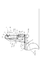
図1、図2、図3および図4は、本発明の荷受台昇降装置の一実施形態を示す側面図である。図5は、図4に示した状態にある荷受台昇降装置の背面図である。この荷受台昇降装置1は、貨物車両Cの荷台11上に取り付けられる装置本体Uを備えており、地上と荷台11上との間で荷物の積み降ろしを行なうために利用されるものである。荷台11上の後端部には、車両走行時に起立した状態とする後部の煽戸(開閉扉)10が設けられている。また、図5において、荷台11上の車幅方向の側端部には、車両走行時に起立した状態とする側部の煽戸20が設けられている。
Hereinafter, embodiments of the present invention will be described with reference to the drawings.
1, FIG. 2, FIG. 3 and FIG. 4 are side views showing an embodiment of the load receiving table lifting device of the present invention. FIG. 5 is a rear view of the load receiving table lifting device in the state shown in FIG. 4. The load receiving platform lifting / lowering device 1 includes a device main body U that is mounted on a load carrier 11 of a cargo vehicle C, and is used for loading and unloading loads between the ground and the load carrier 11. A rear side door (opening / closing door) 10 is provided at the rear end portion of the loading platform 11 so as to stand up when the vehicle is traveling. Further, in FIG. 5, a side door 20 is provided at a side end portion in the vehicle width direction on the loading platform 11 so as to stand in a standing state when the vehicle travels.

これら煽戸10,20それぞれは、荷台11の縁部に設けられたヒンジによって上下方向に回動して開閉可能となっていて、閉状態で荷台11の縁部から立ち上がった状態(図4と図5参照)となり、開状態で、荷台11の縁部から下方へ垂れ下がった状態となる(図1〜図3参照)。また、荷台11には、起立した煽戸10,20をその起立姿勢で固縛する固縛部(図示せず)が設けられている。固縛部は、使用者によって操作され、煽戸10,20を起立姿勢(閉状態)に拘束する固縛状態と、開状態可能とする解除状態とのいずれかに切り替えられる。なお、図5では、後部の煽戸10は開状態にある。煽戸10,20は、鋼板等によって製造されている。   Each of these doors 10 and 20 can be opened and closed by being pivoted in the vertical direction by a hinge provided at the edge of the loading platform 11, and standing up from the edge of the loading platform 11 in a closed state (see FIG. 4). 5), and in the open state, the bag 11 hangs downward from the edge of the loading platform 11 (see FIGS. 1 to 3). The loading platform 11 is provided with a securing portion (not shown) that secures the standing doors 10 and 20 in the standing posture. The lashing portion is operated by the user, and is switched between a lashing state in which the doors 10 and 20 are restrained in a standing posture (closed state) and a release state in which the sashing state is enabled. In FIG. 5, the rear door 10 is in an open state. The doors 10 and 20 are made of a steel plate or the like.

荷受台昇降装置1の装置本体Uは、荷物を載せる荷受台2を備えており、この荷受台2は、荷物を載せる載置面2aを表面に有する盤状の荷受台本体21を有している。図示している装置本体Uは、荷台11の上面11aの後端部に取り付けられており、荷受台2は、荷台11の後端部の上方の上位置と、車両後方において地上に接地する接地位置との間を昇降する。車両前後方向が、図1〜図3の状態にある荷受台2の奥行き方向と一致しており、車幅方向(車両Cの左右方向)が、荷受台2の幅方向と一致している。   The apparatus main body U of the load receiving platform lifting / lowering device 1 includes a load receiving platform 2 on which a load is placed. The load receiving platform 2 has a plate-shaped load receiving platform main body 21 having a mounting surface 2a on which a load is placed. Yes. The illustrated apparatus body U is attached to the rear end portion of the upper surface 11a of the loading platform 11, and the loading platform 2 is grounded to the ground above the rear end portion of the loading platform 11 and to the ground behind the vehicle. Move up and down between positions. The vehicle front-rear direction matches the depth direction of the load receiving platform 2 in the state of FIGS. 1 to 3, and the vehicle width direction (the left-right direction of the vehicle C) matches the width direction of the load receiving platform 2.

装置本体Uは、荷受台2の他に、荷台11の上面11aに取り付けられるベースブラケット(ベース部)3と、荷受台2を支持している支持体7と、ベースブラケット3と支持体7とを連結しているアーム体4と、伸縮するリフトシリンダ5と、このリフトシリンダ5を駆動するパワーユニット6とを備えている。ベースブラケット3、アーム体4および支持体7は、荷台11の後部において、車幅方向の一方側の端部に設けられている(図5参照)。そして、荷受台2は車幅方向の中央寄りの位置に設けられている。   In addition to the cargo cradle 2, the apparatus main body U includes a base bracket (base portion) 3 attached to the upper surface 11 a of the cargo cradle 11, a support 7 that supports the cargo cradle 2, a base bracket 3, and a support 7. Are connected to each other, a lift cylinder 5 that expands and contracts, and a power unit 6 that drives the lift cylinder 5. The base bracket 3, the arm body 4, and the support body 7 are provided at the end of one side in the vehicle width direction at the rear part of the loading platform 11 (see FIG. 5). And the goods receiving stand 2 is provided in the position near the center of the vehicle width direction.

前記ベースブラケット3は、固定手段としてのボルト12およびナット体27により、荷台11の上面11aの後部に固定および固定解除可能に取り付けられている。これにより、装置本体Uの貨物車両Cへの取り付けが簡単であり、また、貨物車両C側において、ボルト孔を形成すればよく、大きな改造が不要である。   The base bracket 3 is attached to a rear portion of the upper surface 11a of the loading platform 11 so as to be fixed and unfixable by a bolt 12 and a nut body 27 as fixing means. Thereby, the attachment of the apparatus main body U to the freight vehicle C is simple, and a bolt hole may be formed on the freight vehicle C side, and no major modification is required.

前記アーム体4は、第一アーム13と第二アーム14とを有しており、平行リンクを構成している。第一アーム13は、ベースブラケット3から一方向に延びている部材であり、第一アーム13の基部13aはベースブラケット3の上部に回動可能に取り付けられており、先部13bは支持体7(後述する側部支持フレーム7a)の上部に回動可能に取り付けられている。第二アーム14は、ベースブラケット3から第一アーム13に沿って延びている部材であり、第二アーム14の基部14aはベースブラケット3に回動可能に取り付けられており、先部14bは支持体7(側部支持フレーム7a)に回動可能に取り付けられている。   The arm body 4 has a first arm 13 and a second arm 14 and constitutes a parallel link. The first arm 13 is a member extending in one direction from the base bracket 3, the base portion 13 a of the first arm 13 is rotatably attached to the upper portion of the base bracket 3, and the tip portion 13 b is the support 7. It is rotatably attached to the upper part of a (side support frame 7a described later). The second arm 14 is a member extending from the base bracket 3 along the first arm 13, the base portion 14 a of the second arm 14 is rotatably attached to the base bracket 3, and the tip portion 14 b is supported. The body 7 (side support frame 7a) is rotatably attached.

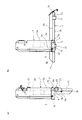
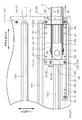
そして、アーム体4は、ベースブラケット3から上方へ延びている起立位置(図1)と、車両後方でかつ地上へ向かう斜め下方に延びている後方位置(図3)との間を揺動することができる。このアーム体4によって、支持体7および荷受台2は、荷台11後部の上面11aより上方の上位置(図1)と車両後方において地上に接地する接地位置(図3)との間を昇降することができる。また、図1〜図3に示しているように、アーム体4は平行リンクを構成していることから、荷受台2(荷受台本体21)を水平姿勢としたまま昇降させることができる。   The arm body 4 swings between a standing position (FIG. 1) extending upward from the base bracket 3 and a rear position (FIG. 3) extending rearward and obliquely downward toward the ground. be able to. With this arm body 4, the support body 7 and the load receiving platform 2 are moved up and down between an upper position (FIG. 1) above the upper surface 11 a of the rear portion of the loading platform 11 and a grounding position (FIG. 3) that contacts the ground behind the vehicle. be able to. Moreover, as shown in FIGS. 1-3, since the arm body 4 comprises the parallel link, it can be raised / lowered with the load receiving stand 2 (load receiving stand main body 21) made into a horizontal attitude | position.

図5において、荷受台2は、表面が荷物を載せる載置面2aとなる前記荷受台本体21と、この荷受台本体21に取り付けられた第一の支持部材22とを有している。この支持部材22は、荷受台2の幅方向に直線的に延びている部材であり、荷受台本体21の裏面側に固定されていて、荷受台本体21の側部からさらに外側方へ一部が突出している部材である。また、荷受台本体21の裏面には、第二の支持部材23が設けられている。この支持部材23は、荷受台本体21の幅方向寸法と略同じ長さである。図示している形態では、支持部材22,23は中空の角パイプによって構成されていて、荷受台本体21の幅方向の梁部材(強度部材)として機能している。   In FIG. 5, the load receiving platform 2 includes the load receiving platform main body 21 whose surface is a placement surface 2 a on which a load is placed, and a first support member 22 attached to the load receiving platform main body 21. The support member 22 is a member that linearly extends in the width direction of the cargo cradle 2, is fixed to the back side of the cargo cradle body 21, and is further partially outward from the side of the cargo cradle body 21. Is a protruding member. A second support member 23 is provided on the back surface of the cargo receiving body 21. The support member 23 has substantially the same length as the width direction dimension of the cargo receiving table main body 21. In the illustrated form, the support members 22 and 23 are constituted by hollow square pipes and function as beam members (strength members) in the width direction of the load receiving table main body 21.

前記支持体7は、側部支持フレーム7aを有しており、この側部支持フレーム7aの下部に、ヒンジ部8を介して前記第一の支持部材22が取り付けられている。側部支持フレーム7aは、縦長の箱形状であり、アーム体4およびリフトシリンダ5を格納し、かつ、アーム体4およびリフトシリンダ5を機能させるために車両前方に開口している。   The support 7 has a side support frame 7a, and the first support member 22 is attached to the lower part of the side support frame 7a via a hinge portion 8. The side support frame 7a has a vertically long box shape, and houses the arm body 4 and the lift cylinder 5 and opens in front of the vehicle in order to make the arm body 4 and the lift cylinder 5 function.

図6は前記ヒンジ部8を説明する説明図である。ヒンジ部8は、荷受台2を姿勢変化可能として支持体7に取り付けている。ヒンジ部8は、側部支持フレーム7aに固定された第一ブラケット部8aと、支持部材22に固定された第二ブラケット部8bと、第二ブラケット部8bを第一ブラケット部8aに回動自在として取り付けているヒンジ軸8cとを有している。ヒンジ軸8cの中心線は水平でかつ荷受台2の幅方向である。このヒンジ部8により、支持部材22に固定された荷受台本体21は、側部支持フレーム7aに対して水平軸心a回りに起伏回動自在となる。これにより、荷受台2を荷物の積み降ろしに利用しない車両走行時に、荷受台本体21は荷台11上の上位置で起立姿勢となり、(図4、図6(a)参照)、荷物の積み降ろし作業時に荷受台本体21は水平姿勢となることができる(図1、図6(b)参照)。   FIG. 6 is an explanatory view for explaining the hinge portion 8. The hinge portion 8 is attached to the support 7 so that the load receiving platform 2 can change its posture. The hinge part 8 is rotatable to the first bracket part 8a, the first bracket part 8a fixed to the side support frame 7a, the second bracket part 8b fixed to the support member 22, and the second bracket part 8b. As a hinge shaft 8c. The center line of the hinge shaft 8 c is horizontal and the width direction of the load receiving platform 2. The hinge base 8 allows the load receiving body 21 fixed to the support member 22 to swing up and down around the horizontal axis a with respect to the side support frame 7a. As a result, when the vehicle travels without using the load receiving platform 2 for loading and unloading the load, the load receiving platform main body 21 is in an upright position on the loading platform 11 (see FIGS. 4 and 6A), and the loading and unloading of the load is performed. During operation, the load receiving body 21 can be in a horizontal posture (see FIGS. 1 and 6B).

図1において、第一の支持部材22は、水平姿勢にある荷受台本体21の奥行き方向(車両前後方向)の中間部に取り付けられている。なお、荷受台本体21が起立姿勢にある場合(図4参照)は、高さ方向の中間部である。そして、この支持部材22に前記ヒンジ部8が取り付けられていることから、側面視において、荷受台2の回動中心(水平軸心a)は、荷受台本体21の奥行き方向の中間部に位置する。この構成により、荷受台本体21の内の、前記水平軸心aよりも車両前方側の部分(荷受台2の基端部2b側の部分)は、荷受台2が起立した姿勢(図4参照)で、当該水平軸心aよりも下方に位置する。このように、荷受台本体21の一部を、水平軸心aよりも下方でかつ荷台11の上面11aの上方に位置させるために、荷台11の上面11aからの第一の支持部材22の設置位置は高く設定されている。具体的には、図4に示しているように、起立させた煽戸10の上部と対向する高さ位置に支持部材22が存在するように、装置本体Uは構成されている。   In FIG. 1, the first support member 22 is attached to an intermediate portion in the depth direction (vehicle longitudinal direction) of the load receiving table main body 21 in a horizontal posture. In addition, when the load receiving body 21 is in the standing posture (see FIG. 4), it is an intermediate portion in the height direction. And since the said hinge part 8 is attached to this support member 22, the rotation center (horizontal axis a) of the load receiving stand 2 is located in the intermediate part of the depth direction of the load receiving stand main body 21 in side view. To do. With this configuration, a portion of the load receiving body 21 on the front side of the vehicle with respect to the horizontal axis a (a portion on the base end 2b side of the load receiving stand 2) is a posture in which the load receiving stand 2 stands (see FIG. 4). ) Is located below the horizontal axis a. In this way, in order to position a part of the cargo bed main body 21 below the horizontal axis a and above the upper surface 11a of the cargo bed 11, the first support member 22 is installed from the upper surface 11a of the cargo bed 11. The position is set high. Specifically, as shown in FIG. 4, the apparatus main body U is configured such that the support member 22 exists at a height position facing the upper part of the upright door 10.

そして、荷物の積み降ろしを行なう使用状態(図1〜図3の状態)とするためには、荷受台2をヒンジ部8で回動させ、荷受台本体21を水平姿勢として載置面2aが上を向く状態とする。図6において、荷受台本体21を水平姿勢に維持するために、ヒンジ部8の第一ブラケット部8aと第二ブラケット8bとの間に接触部9aおよび被接触部9bとが設けられている。図6では、ボルトからなる接触部9aが第二ブラケット部8bに設けられていて、荷受台本体21が水平姿勢となると、この接触部9a(ボルトの頭)が、第一ブラケット部8aの一部(被接触部9b)に当接する。これにより、荷受台本体21が水平姿勢を越えて回動し過ぎることを規制している。   And in order to make it the use state (state of FIGS. 1-3) which loads and unloads a load, the load receiving stand 2 is rotated by the hinge part 8, the load receiving stand main body 21 is made into a horizontal posture, and the mounting surface 2a Set to face up. In FIG. 6, a contact portion 9 a and a contacted portion 9 b are provided between the first bracket portion 8 a and the second bracket 8 b of the hinge portion 8 in order to maintain the load receiving table main body 21 in a horizontal posture. In FIG. 6, when the contact portion 9a made of a bolt is provided in the second bracket portion 8b and the load receiving base body 21 is in a horizontal posture, the contact portion 9a (the head of the bolt) is one of the first bracket portions 8a. It abuts on the part (contacted part 9b). This restricts the load receiving table body 21 from rotating too much beyond the horizontal posture.

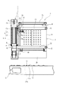
そして、荷台11上の上位置にあって水平姿勢にある荷受台2をヒンジ部8において90°回動させて起立させることにより、図4および図6(a)に示しているように、荷受台2は側部支持フレーム7aに対して折り畳まれた格納状態となる。この状態では、荷受台2の基端部2bが下位置となり、先端部2cが上位置となり、基端部2bと先端部2cとが同一鉛直面上に配置される。   Then, as shown in FIG. 4 and FIG. 6 (a), the load receiving platform 2 which is in the upper position on the loading platform 11 and is in a horizontal posture is turned by 90 ° in the hinge portion 8 to stand. The table 2 is in a retracted state folded with respect to the side support frame 7a. In this state, the base end 2b of the load receiving platform 2 is in the lower position, the front end 2c is in the upper position, and the base end 2b and the front end 2c are arranged on the same vertical plane.

また、図5において、装置本体Uは、荷受台2を前記起立姿勢で維持するための起立ロック装置17を有している。この起立ロック装置17は、起立姿勢にある荷受台2が前方および後方へ倒れる方向に回動することを規制している。具体的には、図7に示すように、起立ロック装置17は、荷受台2に設けられた係合部材17aと、支持体7に設けられた被係合部材17bとを有しており、係合部材17aおよび荷受台2の側端縁が、被係合部材17bに一体形成された前板部17b1と後板部17b2との間に挿入することにより、荷受台2は起立姿勢で維持される。   Further, in FIG. 5, the apparatus main body U has a standing lock device 17 for maintaining the load receiving stand 2 in the standing posture. The standing lock device 17 restricts the load receiving platform 2 in the standing posture from rotating in a direction that falls forward and backward. Specifically, as shown in FIG. 7, the standing lock device 17 includes an engagement member 17 a provided on the load receiving platform 2 and an engaged member 17 b provided on the support 7. The side edges of the engaging member 17a and the load receiving platform 2 are inserted between the front plate portion 17b1 and the rear plate portion 17b2 formed integrally with the engaged member 17b, so that the load receiving table 2 is maintained in a standing posture. Is done.

係合部材17aは、弾性部材(バネ)17cにより常に係合方向(図7の矢符b方向)に付勢されている。このため、荷受台2を上方回動させて起立姿勢となる直前で、係合部材17aの先端に形成された傾斜面(図示せず)が被係合部材17bの後板部17b2に当接することによって、弾性部材17cの付勢力を抗して係合方向と逆方向へ移動しながら、その後板部17b2を乗り越える。そして、係合部材17aは、被係合部材17bを乗り越えると、弾性部材17cの付勢力により係合方向へ押されて前板部17b1と後板部17b2との間に挿入される。すなわち、起立ロック装置17は、荷受台2を起立姿勢まで上方回動させたときに、荷受台2を自動的に起立姿勢で維持するロック状態となる。これにより、係合部材17aが後板部17b2に当接することにより、起立姿勢の荷受台2が前方へ倒れるのを規制することができる。また、荷受台2の前面(載置面2a)が前板部17b1に固定されたクッションゴム17b3に当接することにより、荷受台2が前方へ倒れるのを規制することができる。
また、起立ロック装置17は、係合部材17aを被係合部材17bから抜き挿し動作させる操作杆17dを有している。作業者がこの操作杆17dを操作(押し引き)することで、前記ロック状態と、このロック状態を解除する非ロック状態とに切り替えることができる。
The engaging member 17a is always urged in the engaging direction (the arrow b direction in FIG. 7) by the elastic member (spring) 17c. For this reason, an inclined surface (not shown) formed at the front end of the engaging member 17a comes into contact with the rear plate portion 17b2 of the engaged member 17b immediately before the load receiving platform 2 is rotated upward to assume the standing posture. As a result, the plate member 17b2 is then climbed over while moving in the direction opposite to the engaging direction against the urging force of the elastic member 17c. When the engaging member 17a gets over the engaged member 17b, it is pushed in the engaging direction by the urging force of the elastic member 17c and inserted between the front plate portion 17b1 and the rear plate portion 17b2. That is, the standing lock device 17 is in a locked state in which the load receiving platform 2 is automatically maintained in the standing posture when the load receiving platform 2 is rotated upward to the standing posture. Thereby, when the engaging member 17a contacts the rear plate portion 17b2, it is possible to prevent the load receiving platform 2 in the standing posture from falling forward. In addition, the front surface (mounting surface 2a) of the load receiving platform 2 abuts against the cushion rubber 17b3 fixed to the front plate portion 17b1, so that the load receiving platform 2 can be prevented from falling forward.
Further, the standing lock device 17 has an operating rod 17d that allows the engaging member 17a to be inserted and removed from the engaged member 17b. When the operator operates (pushes and pulls) the operating rod 17d, the locked state and the unlocked state for releasing the locked state can be switched.

本発明の荷受台昇降装置1は、装置本体Uが荷台11から取り外し可能となっているため、装置本体Uには、当該装置本体Uをクレーンなどで吊り下げるための吊り部材が設けられる。具体的には、図7において、起立ロック装置17の被係合部材17bの上部にアイボルトからなる吊り部材17eが取り付けられるようになっている。すなわち、被係合部材17bの上部にネジ孔17b4が形成され、このネジ孔17b4に吊り部材17eが着脱可能に固定される。この構成によれば、図15に示すように、吊り部材17eにクレーン19のフック19aを係合させることができ、装置本体Uを吊り下げることが可能となる。そして、荷受台2を格納状態に維持する起立ロック装置17を、吊り部材17eを取り付けるブラケットとして兼用していることから、部品点数を削減し、製造コストを低減することができる。   In the load receiving platform lifting / lowering apparatus 1 of the present invention, since the apparatus main body U can be detached from the load carrier 11, the apparatus main body U is provided with a suspension member for hanging the apparatus main body U with a crane or the like. Specifically, in FIG. 7, a suspension member 17 e made of an eyebolt is attached to the upper portion of the engaged member 17 b of the standing lock device 17. That is, the screw hole 17b4 is formed in the upper part of the engaged member 17b, and the suspension member 17e is detachably fixed to the screw hole 17b4. According to this configuration, as shown in FIG. 15, the hook 19a of the crane 19 can be engaged with the suspension member 17e, and the apparatus main body U can be suspended. And since the standing lock device 17 which maintains the load receiving stand 2 in the retracted state is also used as a bracket for attaching the suspension member 17e, the number of parts can be reduced and the manufacturing cost can be reduced.

さらに、図5において、装置本体Uは、荷受台2を水平姿勢で維持するための水平ロック装置18を有している。この水平ロック装置18は、水平姿勢にある荷受台本体21が起立姿勢となる方向に回動することを規制している。このロック装置18は作業者によって操作され、荷受台2を水平姿勢に維持するロック状態と、このロック状態を解除する非ロック状態とに切り替えられる。具体的には、図8に示すように、水平ロック装置18は、荷受台2に設けられた係合部材18aと、支持体7に設けられた被係合部材18bとを有しており、係合部材18aが被係合部材18bに係合することにより、荷受台2は水平姿勢で維持される。   Furthermore, in FIG. 5, the apparatus main body U has the horizontal lock apparatus 18 for maintaining the load receiving stand 2 in a horizontal attitude | position. The horizontal lock device 18 restricts the load receiving base body 21 in a horizontal posture from rotating in a direction in which it is in a standing posture. The lock device 18 is operated by an operator, and is switched between a locked state in which the load receiving platform 2 is maintained in a horizontal position and an unlocked state in which the locked state is released. Specifically, as shown in FIG. 8, the horizontal lock device 18 includes an engaging member 18 a provided on the load receiving platform 2 and an engaged member 18 b provided on the support 7. When the engaging member 18a is engaged with the engaged member 18b, the cargo receiving platform 2 is maintained in a horizontal posture.

係合部材18aは、弾性部材(バネ)18cにより常に係合方向(図8の矢符c方向)に付勢されている。このため、荷受台2を下方回動させて水平姿勢となる直前で、係合部材18aが被係合部材18bの下方から接近(図8の矢符d方向に移動)し、係合部材18aの先端に形成された傾斜面18a1が被係合部材18bに当接しながらその被係合部材18bを乗り越える。そして、係合部材18aは、被係合部材18bを乗り越えると、弾性部材18cの付勢力により係合方向へ押されて被係合部材18bに係合される。すなわち、水平ロック装置18は、荷受台2を水平姿勢まで下方回動させたときに、荷受台2を自動的に水平姿勢で維持するロック状態となる。なお、この状態で荷受台2を下降させて接地位置とした場合には、支持体7が接地位置の荷受台2に対してヒンジ部8を中心に後方へ倒れる方向へ回動することも規制することができる。
また、水平ロック装置18は、係合部材18aを被係合部材18bに係脱させる操作杆18dを有している(図5参照)。作業者がこの操作杆18dを操作(押し引き)することで、前記ロック状態と、このロック状態を解除する非ロック状態とに切り替えることができる。
The engaging member 18a is always urged in the engaging direction (the arrow c direction in FIG. 8) by an elastic member (spring) 18c. Therefore, immediately before the load receiving platform 2 is rotated downward to be in the horizontal posture, the engaging member 18a approaches (moves in the direction of the arrow d in FIG. 8) from below the engaged member 18b, and the engaging member 18a. The inclined surface 18a1 formed at the front end of the member gets over the engaged member 18b while contacting the engaged member 18b. When the engaging member 18a gets over the engaged member 18b, the engaging member 18a is pushed in the engaging direction by the urging force of the elastic member 18c and engaged with the engaged member 18b. That is, the horizontal lock device 18 is in a locked state in which the load receiving platform 2 is automatically maintained in the horizontal posture when the load receiving platform 2 is rotated downward to the horizontal posture. In this state, when the load receiving platform 2 is lowered to the grounding position, the support 7 is also restricted from rotating backward with respect to the load receiving platform 2 at the grounding position around the hinge portion 8. can do.
Further, the horizontal locking device 18 has an operating rod 18d for engaging and disengaging the engaging member 18a with the engaged member 18b (see FIG. 5). The operator can switch between the locked state and the unlocked state in which the locked state is released by operating (pushing and pulling) the operating rod 18d.

図1〜図3において、前記リフトシリンダ5は、荷受台2を昇降させるために伸縮する複動式の油圧シリンダ(流体アクチュエータ)であり、アーム体4と支持体7との間に取り付けられている。リフトシリンダ5の一端部5aは、第一アーム13に回動自在として取り付けられており、リフトシリンダ5の他端部5bは、側部支持フレーム7aの下部に回動自在として取り付けられている。
前記パワーユニット6は、リフトシリンダ5を伸縮させる油圧ユニットであり、パワーユニット6とリフトシリンダ5とにより、荷受台2を昇降駆動する昇降駆動機構Lを構成している。
1 to 3, the lift cylinder 5 is a double-acting hydraulic cylinder (fluid actuator) that expands and contracts to raise and lower the load receiving table 2, and is attached between the arm body 4 and the support body 7. Yes. One end 5a of the lift cylinder 5 is rotatably attached to the first arm 13, and the other end 5b of the lift cylinder 5 is rotatably attached to the lower part of the side support frame 7a.
The power unit 6 is a hydraulic unit that expands and contracts the lift cylinder 5, and the power unit 6 and the lift cylinder 5 constitute an elevating drive mechanism L that elevates and lowers the load receiving platform 2.

パワーユニット6がリフトシリンダ5に対して作動油(作動流体)の供給の切り替えを行なうことにより、リフトシリンダ5は伸縮動作を行うことができる。パワーユニット6の動作は、パワーユニット6に設けられている図示していない制御装置によって制御される。作業者が側部支持フレーム7に設けられた操作部7e(図5参照)を操作することにより、前記制御装置がパワーユニット6に所定の動作を行なわせる。   When the power unit 6 switches the supply of hydraulic oil (working fluid) to the lift cylinder 5, the lift cylinder 5 can perform an expansion / contraction operation. The operation of the power unit 6 is controlled by a control device (not shown) provided in the power unit 6. When the operator operates the operation unit 7e (see FIG. 5) provided on the side support frame 7, the control device causes the power unit 6 to perform a predetermined operation.

図9は、前記昇降駆動機構Lの油圧回路図を示すものである。パワーユニット6は、作動油を溜めるタンクT、作動油を吐出させるためのポンプ40、このポンプ40を駆動する正逆回転可能なモータ41、タンクT内の作動油をポンプ40に供給するための切換弁42と、リフトシリンダ5のヘッド側室5cおよびロッド側室5dの各作動油がポンプ40側へ排出(供給)されるのを規制する規制手段43としての2個の逆止弁(パイロットチェックバルブ)43a,43bと、4個のリリーフ弁44a〜44dと、逆止弁付き絞り弁45と、緊急用切換弁46とを一体として備えている油圧ユニットであり、このパワーユニット6は、リフトシリンダ5とともに側部支持フレーム7aに取り付けられている。   FIG. 9 shows a hydraulic circuit diagram of the lifting drive mechanism L. As shown in FIG. The power unit 6 includes a tank T for storing hydraulic oil, a pump 40 for discharging hydraulic oil, a motor 41 that can rotate forward and reverse, and a switch for supplying hydraulic oil in the tank T to the pump 40. Two check valves (pilot check valves) as regulating means 43 for regulating the discharge of the valve 42 and the hydraulic oil in the head side chamber 5c and the rod side chamber 5d of the lift cylinder 5 to the pump 40 side 43a, 43b, four relief valves 44a to 44d, a throttle valve 45 with a check valve, and an emergency switching valve 46 are integrated, and this power unit 6 is combined with the lift cylinder 5. It is attached to the side support frame 7a.

前記切換弁42は三位置電磁弁からなり、モータ41を停止させているときは、図9に示すように、左右のバネ42aおよび42bの各付勢力が均等に作用することにより、中立位置42Nの状態に保持されている。
この状態から、リフトシリンダ5を伸長させる際は、モータ41を正転させ、ポンプ40の吐出口(この場合は図9の左側)から吐出される作動油を、逆止弁43aを介してヘッド側室5cに供給する。このとき、前記作動油のパイロット圧が切換弁42の左位置42Lおよび逆止弁43bに作用することにより、切換弁42が左位置42Lに切り換わるとともに逆止弁43bが開いて作動油が図9の上側から下側へ流れるのを許容する。これにより、ロッド側室5d内の作動油が逆止弁43bを介してポンプ40の吸込口(この場合は図9の右側)に供給されるとともに、タンクTの作動油が油路47から吸い上げられて切換弁42を介してポンプ40の吸込口に供給され、リフトシリンダ5が伸長動作する。
The switching valve 42 is a three-position electromagnetic valve. When the motor 41 is stopped, as shown in FIG. 9, the biasing forces of the left and right springs 42a and 42b act equally, so that the neutral position 42N Is held in the state.
In this state, when the lift cylinder 5 is extended, the motor 41 is rotated in the forward direction, and the hydraulic oil discharged from the discharge port of the pump 40 (in this case, the left side in FIG. 9) is passed through the check valve 43a. Supply to the side chamber 5c. At this time, the pilot pressure of the hydraulic oil acts on the left position 42L and the check valve 43b of the switching valve 42, whereby the switching valve 42 is switched to the left position 42L and the check valve 43b is opened, so that the hydraulic oil is drawn. 9 is allowed to flow from the upper side to the lower side. As a result, the hydraulic oil in the rod side chamber 5d is supplied to the suction port of the pump 40 (in this case, the right side in FIG. 9) via the check valve 43b, and the hydraulic oil in the tank T is sucked up from the oil passage 47. Then, the air is supplied to the suction port of the pump 40 through the switching valve 42, and the lift cylinder 5 extends.

また、リフトシリンダ5を収縮させる際は、モータ41を逆転させ、ポンプ40の吐出口(この場合は図9の右側)から吐出される作動油を、逆止弁43bを介してロッド側室5dに供給する。このとき、前記作動油のパイロット圧が切換弁42の右位置42Rおよび逆止弁43aに作用することにより、切換弁42が右位置42Rに切り換わるとともに逆止弁43aが開いて作動油が図9の上側から下側へ流れるのを許容する。これにより、ヘッド側室5c内の作動油が逆止弁43aを介してポンプ40の吸込口(この場合は図9の左側)に供給されるとともに、タンクTの作動油が油路47および切換弁42を介してポンプ40の吸込口に供給され、リフトシリンダ5が収縮動作する。
さらに、モータ41を停止してポンプ40の駆動を停止すると、切換弁42には作動油のパイロット圧が作用しなくなり、切換弁42は左右のバネ42aおよび42bの各付勢力により中立位置42Nに切り換わる。この状態において、リフトシリンダ5の両側室5c,5d内の各作動油は、逆止弁43aおよび43bにより、ポンプ42側へ排出されるのを規制することができる。
Further, when the lift cylinder 5 is contracted, the motor 41 is reversely rotated, and the hydraulic oil discharged from the discharge port of the pump 40 (in this case, the right side in FIG. 9) is supplied to the rod side chamber 5d via the check valve 43b. Supply. At this time, when the pilot pressure of the hydraulic oil acts on the right position 42R and the check valve 43a of the switching valve 42, the switching valve 42 is switched to the right position 42R and the check valve 43a is opened, so that the hydraulic oil is drawn. 9 is allowed to flow from the upper side to the lower side. As a result, the hydraulic oil in the head side chamber 5c is supplied to the suction port of the pump 40 (in this case, the left side in FIG. 9) via the check valve 43a, and the hydraulic oil in the tank T is supplied to the oil passage 47 and the switching valve. The lift cylinder 5 is contracted by being supplied to the suction port of the pump 40 through 42.
Further, when the motor 41 is stopped and the driving of the pump 40 is stopped, the pilot pressure of the hydraulic oil does not act on the switching valve 42, and the switching valve 42 is moved to the neutral position 42N by the urging forces of the left and right springs 42a and 42b. Switch. In this state, the hydraulic oil in the side chambers 5c and 5d of the lift cylinder 5 can be restricted from being discharged to the pump 42 side by the check valves 43a and 43b.

この昇降駆動機構Lによれば、上述のようにパワーユニット6によりリフトシリンダ5を収縮動作させると、アーム体4が上方回動して地上にあった荷受台2(図3)が支持体7とともに上昇し、図2の状態を経て、図1のように荷受台2を荷台11の上方の上位置へと上昇させることができる。そして、パワーユニット6によりリフトシリンダ5を伸長動作させると、アーム体4が下方回動して荷受台2が支持体7とともに上位置から地上へと下降する。この昇降駆動機構Lにより、荷受台2に載せた荷物を地上と荷台11上との間で積み降ろすための昇降動作が実行される。   According to this lifting drive mechanism L, when the lift cylinder 5 is contracted by the power unit 6 as described above, the arm 4 rotates upward and the load receiving platform 2 (FIG. 3) that is on the ground together with the support 7. As shown in FIG. 1, the load receiving platform 2 can be raised to the upper position above the loading platform 11 through the state shown in FIG. 2. Then, when the lift cylinder 5 is extended by the power unit 6, the arm body 4 is rotated downward, and the load receiving platform 2 is lowered together with the support body 7 from the upper position to the ground. By this elevating drive mechanism L, an elevating operation for loading and unloading the load placed on the load receiving platform 2 between the ground and the load platform 11 is executed.

また、パワーユニット6の駆動を停止すると、逆止弁43a,43bにより、リフトシリンダ5のヘッド側室5cおよびロッド側室5d内の作動油がポンプ40側へ排出されるのが規制される。これにより、各側室5c,5d内の作動油圧によって、アーム体4を任意の回動位置で保持させることができる。したがって、荷受台2を上位置および接地位置とした状態においてパワーユニット6の駆動を停止することにより、逆止弁43a,43bは、アーム体4を前記各位置の回動位置に保持させることができる回動保持手段としての機能も兼ねている。   When the driving of the power unit 6 is stopped, the check valves 43a and 43b restrict the hydraulic oil in the head side chamber 5c and the rod side chamber 5d of the lift cylinder 5 from being discharged to the pump 40 side. Thereby, the arm body 4 can be held at an arbitrary rotational position by the hydraulic pressure in each of the side chambers 5c and 5d. Therefore, the check valve 43a, 43b can hold the arm body 4 at the rotation position of each position by stopping the driving of the power unit 6 in the state where the load receiving platform 2 is in the upper position and the ground contact position. It also functions as a rotation holding means.

そして、上位置にある荷受台2をヒンジ部8によって前記水平軸線a回りに回動させることで、荷受台2を起立姿勢(図4参照)に変化させることができる。この状態で、貨物車両Cは走行可能となる。また、貨物車両Cを走行させる際に、煽戸10を起立させ、荷台11の後部を閉状態としている。この状態において、荷受台2に裏面側に固定された当接部15が、起立している煽戸10の上部に当接することにより、上位置で起立姿勢にある荷受台2の基端部2bが、車両Cの走行中の振動等によりバタつくのを防止している。この当接部15は、ゴム,樹脂,木材等の非金属製であって、図5に示すように荷受台2の裏面側の四箇所に固定されており、水平姿勢にある荷受台2が地上に降りた際に当該地上に接触して荷受台2と地上との干渉を防止する緩衝部材としても機能している(図3参照)。   And the load receiving stand 2 can be changed to a standing posture (refer FIG. 4) by rotating the load receiving stand 2 in the upper position around the said horizontal axis line a by the hinge part 8. FIG. In this state, the freight vehicle C can run. Further, when the cargo vehicle C is driven, the door 10 is raised and the rear part of the loading platform 11 is closed. In this state, the contact portion 15 fixed to the back surface side of the load receiving platform 2 contacts the upper portion of the standing door 10 so that the base end portion 2b of the load receiving platform 2 in the upright position at the upper position. However, it prevents fluttering due to vibration or the like while the vehicle C is traveling. The abutment portion 15 is made of non-metal such as rubber, resin, wood, etc., and is fixed to four places on the back side of the load receiving platform 2 as shown in FIG. When it gets down to the ground, it also functions as a buffer member that contacts the ground and prevents interference between the load receiving platform 2 and the ground (see FIG. 3).

図10は、荷受台昇降装置1と車体側バッテリBとの間の電気配線図である。装置本体Uのアーム体4の第一アーム13または第二アーム14は中空のパイプ部材によって構成されている。図10では、第一アーム13が断面円形のパイプ部材である。第一アーム13をパイプ部材とすることにより、車両Cに搭載されているバッテリBと装置本体Uのパワーユニット6とを接続する電源ケーブルYを、ベースブラケット3から第二アーム14内を通し側部支持フレーム7aへ導き出すことができる。荷台11の上面11aのうちベースブラケット3の直下部分には、バッテリBから延び上面11aの下を通る前記ケーブルYを、ベースブラケット2および第二アーム14へ導き出すための孔(図示せず)が形成されている。また、前記ケーブルYは、荷台2側のケーブルY1と装置本体U側のケーブルY2とからなり、両ケーブルY1およびY2は、接続部16により断接可能に接続されている。このため、装置本体Uを荷台2上から取り外す際に、荷台2側のケーブルY1と装置本体U側のケーブルY2とを分離することができる。   FIG. 10 is an electrical wiring diagram between the load receiving table elevating device 1 and the vehicle body side battery B. The first arm 13 or the second arm 14 of the arm body 4 of the apparatus body U is constituted by a hollow pipe member. In FIG. 10, the first arm 13 is a pipe member having a circular cross section. By using the first arm 13 as a pipe member, the power cable Y connecting the battery B mounted on the vehicle C and the power unit 6 of the apparatus body U is passed from the base bracket 3 through the second arm 14 to the side portion. It can be led to the support frame 7a. A hole (not shown) for guiding the cable Y extending from the battery B and passing under the upper surface 11 a to the base bracket 2 and the second arm 14 is provided in a portion of the upper surface 11 a of the loading platform 11 immediately below the base bracket 3. Is formed. The cable Y includes a cable Y1 on the loading platform 2 side and a cable Y2 on the apparatus main body U side, and both the cables Y1 and Y2 are connected to each other by a connecting portion 16 so as to be connectable / disconnectable. For this reason, when removing the apparatus main body U from the loading platform 2, the cable Y1 on the loading platform 2 side and the cable Y2 on the apparatus main body U side can be separated.

装置本体Uの荷台11上への取り付け構造について説明する。図11および図12は、荷台11上にベースブラケット3を固定する前記固定手段の平面図、およびその固定手段を分解した斜視図である。荷台11の上面11aには、凸部11a1が車両前後方向に延びて形成されている。凸部11a1は、車幅方向に複数、間隔が設けられて配設されている。この凸部11a1は、荷台11の補強リブとして機能し、主として荷台11の車両前後方向の曲げ力に対抗することができる。   A structure for mounting the apparatus main body U on the loading platform 11 will be described. 11 and 12 are a plan view of the fixing means for fixing the base bracket 3 on the loading platform 11, and a perspective view in which the fixing means is disassembled. On the upper surface 11a of the loading platform 11, a convex portion 11a1 is formed extending in the vehicle front-rear direction. A plurality of the convex portions 11a1 are arranged at intervals in the vehicle width direction. The convex portion 11a1 functions as a reinforcing rib of the loading platform 11, and can mainly resist the bending force of the loading platform 11 in the vehicle front-rear direction.

ベースブラケット3は、アーム体4の基部を取り付けているブラケット本体部25と、このブラケット本体部25を荷台11に固定する基礎部26とを有している。基礎部26は、荷台11上に載せられる水平面上に配置された面状部材であり、ブラケット本体部25は、この基礎部26から上に立ち上がっている部材である。   The base bracket 3 includes a bracket main body portion 25 to which the base portion of the arm body 4 is attached, and a base portion 26 that fixes the bracket main body portion 25 to the loading platform 11. The base portion 26 is a planar member disposed on a horizontal plane that is placed on the loading platform 11, and the bracket main body portion 25 is a member that rises upward from the base portion 26.

具体的には、ブラケット本体部25は、幅方向に対向した一対の側壁部25a、前壁部25b、後壁部25c、リブ板25dを有している。側壁部25aにアーム体4の基部が軸部材によって取り付けられる。基礎部26は、前後の第一および第二平板部26a,26bと、左右の第三、第四平板部26c,26dとを有している。前部の第一平板部26aと前壁部25bとは、一枚の板がL字形に曲げられて形成されている(他の平板部及び壁部についても同様である。)そして、ベースブラケット3を構成する部材は鋼材からなり、各部材が溶接によって組み立てられており、ブラケット本体部25と基礎部26とは、一体ものとして構成されている。   Specifically, the bracket main body 25 has a pair of side wall portions 25a, a front wall portion 25b, a rear wall portion 25c, and a rib plate 25d that face each other in the width direction. A base portion of the arm body 4 is attached to the side wall portion 25a by a shaft member. The base portion 26 includes front and rear first and second flat plate portions 26a and 26b, and left and right third and fourth flat plate portions 26c and 26d. The front first flat plate portion 26a and the front wall portion 25b are formed by bending a single plate into an L shape (the same applies to other flat plate portions and wall portions). 3 are made of steel, and each member is assembled by welding, and the bracket main body 25 and the base 26 are configured as an integral unit.

図11において、基礎部26には、上下方向に貫通したボルト孔26eが複数(図11は11個)形成されている。ボルト孔26eの数は、充分な固定強さを有してベースブラケット3を荷台11に固定するために必要なボルト12の数(図11では4本)よりも多く設けられている。以下、このボルト12の数を、ボルト必要数と言う。また、ボルト必要数は、4以上が好ましく、ボルト孔26eの数よりも少ないのが好ましい。   In FIG. 11, the base portion 26 is formed with a plurality of bolt holes 26 e penetrating in the vertical direction (11 pieces in FIG. 11). The number of bolt holes 26e is larger than the number of bolts 12 (four in FIG. 11) necessary to fix the base bracket 3 to the loading platform 11 with sufficient fixing strength. Hereinafter, the number of the bolts 12 is referred to as a required number of bolts. Further, the required number of bolts is preferably 4 or more, and preferably less than the number of bolt holes 26e.

図12において、荷台11には、前記ボルト12を貫通するためのボルト孔11bが形成されている。そして、装置本体U(ベースブラケット3)を荷台11に固定するための固定手段は、第一の固定部材としての前記ボルト12と、第二の固定部材としてのナット体27とを備えている。ナット体27は、1個のナット27aと、3個のナットプレート27b,27c,27dにより構成されている。ナットプレート27bは、車幅方向に長く、ボルト12を取り付けるための複数(図12では6個)のネジ孔27b1が形成されている。このナットプレート27bは、荷台11の下であって車両最後部に配置されており、その一端部(荷台11の車幅方向内側端部)は、ネジ孔27b1にボルト12を取り付け、荷台11に固定されている。他のナットプレート27c,27dについても同様にネジ孔27c1,27d1が形成されている。   In FIG. 12, a bolt hole 11 b for penetrating the bolt 12 is formed in the loading platform 11. And the fixing means for fixing the apparatus main body U (base bracket 3) to the loading platform 11 includes the bolt 12 as the first fixing member and the nut body 27 as the second fixing member. The nut body 27 is configured by one nut 27a and three nut plates 27b, 27c, and 27d. The nut plate 27b is long in the vehicle width direction, and a plurality (six in FIG. 12) of screw holes 27b1 for attaching the bolts 12 are formed. The nut plate 27b is disposed below the loading platform 11 and at the rearmost portion of the vehicle. One end of the nut plate 27b (the inner end in the vehicle width direction of the loading platform 11) is attached to the screw hole 27b1 with bolts 12 and attached to the loading platform 11. It is fixed. Similarly, screw holes 27c1 and 27d1 are formed in the other nut plates 27c and 27d.

本実施の形態では、ナット27aおよびナットプレート27cとボルト12とにより基礎部26の第一平板部26aを、ナットプレート27bとボルト12とにより基礎部26の第二平板部26bを、ナットプレート27bおよび27dとボルト12とにより後述する補強板30を、それぞれ荷台11に固定している。これにより、装置本体Uを、荷台11に取り付けることができる。なお、装置本体Uを荷台11上から取り外す際に、第二平板部26bおよび補強板30を固定しているボルト12をナットプレート27bから外しても、ナットプレート27bの一端は、上述のように荷台11に固定されているため、ナットプレート27bが紛失するのを防止することができる(図14参照)。   In the present embodiment, the nut 27a, the nut plate 27c, and the bolt 12 serve as the first flat plate portion 26a of the base portion 26, and the nut plate 27b and the bolt 12 serve as the second flat plate portion 26b of the base portion 26 as the nut plate 27b. Reinforcing plates 30 which will be described later are fixed to the loading platform 11 by 27d and bolts 12 respectively. Thereby, the apparatus main body U can be attached to the loading platform 11. Even when the bolt 12 that fixes the second flat plate portion 26b and the reinforcing plate 30 is removed from the nut plate 27b when the apparatus body U is removed from the loading platform 11, one end of the nut plate 27b remains as described above. Since it is fixed to the loading platform 11, the nut plate 27b can be prevented from being lost (see FIG. 14).

前記装置本体Uの構成によれば、ベースブラケット3は、アーム体4を介して、荷受台2を昇降可能に搭載しており、当該荷受台2の荷重および荷受台2上の荷物の荷重を支持するものである。このため、荷受台2を昇降させる際に、ベースブラケット3が前記荷重によって車両後方(図11の右側)へ倒れるのを防止するものとして、ベースブラケット3と荷台11の上面11aとの間に補強板30が設けられている。   According to the configuration of the apparatus main body U, the base bracket 3 is mounted with the load receiving table 2 so as to be movable up and down via the arm body 4, and the load on the load receiving table 2 and the load on the load receiving table 2 are loaded. It is something to support. Therefore, when the load receiving platform 2 is moved up and down, the base bracket 3 is reinforced between the base bracket 3 and the upper surface 11a of the loading platform 11 to prevent the base bracket 3 from falling to the rear of the vehicle (right side in FIG. 11) due to the load. A plate 30 is provided.

補強板30は、断面略Z型の鋼板をベースブラケット3の前後長さよりも車両前後方向に長く形成されたものである。補強板30の下端に形成された下水平部30aは、基礎部26の第三平板部26cと、荷台11の上面11aとの間に介在しており、ボルト12とナットプレート27b,27dとにより荷台11上に固定されている。下水平部30aにはボルト12の直径よりも充分に大きな孔が貫通して形成されている。補強板30の上端に形成された上水平部30bと荷台11の上面11aとの間には作業者の手を差し込み可能なスペースが形成されており、装置本体Uを荷台11上から取り外す際に、上水平部30bを装置本体Uを持ち上げるための取手として使用される。
なお、ベースブラケット3が前記荷重によって車幅方向の内側(図11の上側)に倒れるのを防止する補強部材としては、車幅方向に延びて荷台11下に固定されている前記ナットプレート27bが、その機能を兼用している。
The reinforcing plate 30 is a steel plate having a substantially Z-shaped cross section that is longer than the longitudinal length of the base bracket 3 in the longitudinal direction of the vehicle. The lower horizontal portion 30a formed at the lower end of the reinforcing plate 30 is interposed between the third flat plate portion 26c of the base portion 26 and the upper surface 11a of the loading platform 11, and is formed by bolts 12 and nut plates 27b and 27d. It is fixed on the loading platform 11. A hole sufficiently larger than the diameter of the bolt 12 is formed through the lower horizontal portion 30a. A space into which an operator's hand can be inserted is formed between the upper horizontal portion 30 b formed at the upper end of the reinforcing plate 30 and the upper surface 11 a of the loading platform 11, and when removing the apparatus main body U from the loading platform 11. The upper horizontal portion 30b is used as a handle for lifting the apparatus main body U.
As a reinforcing member for preventing the base bracket 3 from falling inward in the vehicle width direction (upper side in FIG. 11) due to the load, the nut plate 27b extending in the vehicle width direction and fixed below the loading platform 11 is provided. , That function is also combined.

前記固定手段は、ベースブラケット3の固定のために、複数の座板28および複数の調節板29を有している。座板28は、荷台11の上面11aと基礎部26との間に介在するものであり、特に上面11aのうちの前記凸部11a1が存在していない平坦面部の上に載せられ、前記ボルト12と前記ナット体27との結合部に配設される。座板28にはボルト12の直径よりも充分に大きな孔が厚さ方向に貫通して形成されている。また、座板28の厚さは、前記平坦面部からの凸部11a1の高さ寸法と同じか当該寸法よりも小さく設定されている。このため、前記寸法よりも小さい場合には、調節板29で座板28の高さを調節するようになっている。調節板29にはボルト12の直径よりも充分に大きな溝が厚さ方向に貫通して形成されている。図12では、車幅方向内側の前後の座板28と基礎部26との間に調節板29が取り付けられている。これにより、ベースブラケット3を、座板28および調節板29を介して、ボルト12とナット体27との間に強固に締め付けることができ、ベースブラケット3を荷受台2に安定して固定することができる。   The fixing means includes a plurality of seat plates 28 and a plurality of adjustment plates 29 for fixing the base bracket 3. The seat plate 28 is interposed between the upper surface 11a of the loading platform 11 and the base portion 26. In particular, the seat plate 28 is placed on the flat surface portion of the upper surface 11a where the convex portion 11a1 does not exist, and the bolt 12 And the nut body 27. A hole sufficiently larger than the diameter of the bolt 12 is formed through the seat plate 28 in the thickness direction. Further, the thickness of the seat plate 28 is set to be the same as or smaller than the height of the convex portion 11a1 from the flat surface portion. For this reason, when it is smaller than the above-mentioned dimension, the height of the seat plate 28 is adjusted by the adjustment plate 29. A groove sufficiently larger than the diameter of the bolt 12 is formed in the adjusting plate 29 so as to penetrate in the thickness direction. In FIG. 12, an adjustment plate 29 is attached between the front and rear seat plates 28 and the base portion 26 on the inner side in the vehicle width direction. Accordingly, the base bracket 3 can be firmly tightened between the bolt 12 and the nut body 27 via the seat plate 28 and the adjustment plate 29, and the base bracket 3 can be stably fixed to the load receiving platform 2. Can do.

各ボルト12およびナット体27は、前記格納状態および水平姿勢の荷受台2を地上に接地させた接地状態(図3)において、装置本体U(ベースブラケット3、アーム体4、支持体7、昇降駆動機構L、および荷受台2)と干渉しない位置に配置されている。すなわち、各ボルト12の上方には、各ボルト12を着脱する際に工具や作業者の手を挿入することができる着脱スペースが設けられている。これにより、各ボルト12およびナット体27を、装置本体Uと干渉することなく外すことができるので、装置本体Uを格納状態および接地状態において、荷台11上から取り外すことができる。
また、前記格納状態および接地状態において、前記各ボルト12をナット体27から外したときに、装置本体Uが荷台11の上面11aで自立するように装置本体Uを構成する各機器が所定の位置に配置され、装置本体Uの重心G位置が設定されている(図14,図17参照)。
Each bolt 12 and the nut body 27 are the main body U (base bracket 3, arm body 4, support body 7, elevating / lowering) in the retracted state and the grounded state (FIG. 3) in which the load receiving stand 2 in the horizontal posture is grounded. It is arranged at a position where it does not interfere with the drive mechanism L and the cargo receiving platform 2). In other words, an attachment / detachment space is provided above each bolt 12 so that a tool or an operator's hand can be inserted when attaching / detaching each bolt 12. Thereby, since each bolt 12 and the nut body 27 can be removed without interfering with the apparatus main body U, the apparatus main body U can be removed from the loading platform 11 in the retracted state and the grounded state.
Further, in the retracted state and the grounded state, when the respective bolts 12 are removed from the nut body 27, the respective devices constituting the device body U are set at predetermined positions so that the device body U can stand on the upper surface 11a of the cargo bed 11. The center of gravity G of the apparatus main body U is set (see FIGS. 14 and 17).

次に、荷台11上に固定されている装置本体Uを荷台11から取り外す方法について、格納状態から取り外す場合と、接地状態から取り外す場合とに分けて、それぞれ図面を参照しながら詳しく説明する。
まず、使用状態にある装置本体Uを格納状態から取り外す場合は、ポンプ40を駆動させてリフトシリンダ5を収縮動作させ、荷受台2を上位置まで上昇させる(図1参照)。上昇後は、ポンプ40の駆動を停止させ、リフトシリンダ5内の作動油が逆止弁43a,43bによりポンプ40側へ排出されるのを規制する(図9参照)。
Next, a method for removing the apparatus main body U fixed on the loading platform 11 from the loading platform 11 will be described in detail with reference to the drawings for each of the removal from the retracted state and the removal from the grounded state.
First, when removing the apparatus main body U in use from the retracted state, the pump 40 is driven to cause the lift cylinder 5 to contract and raise the load receiving platform 2 to the upper position (see FIG. 1). After the rise, the drive of the pump 40 is stopped and the hydraulic oil in the lift cylinder 5 is restricted from being discharged to the pump 40 side by the check valves 43a and 43b (see FIG. 9).

この状態から、手動操作により水平ロック装置18をロック解除し、荷受台2を水平姿勢から起立姿勢まで回動させて格納状態とする(図4参照)。その際、荷受台2は、起立ロック装置17により自動的に起立姿勢で維持されたロック状態となる。また、アーム体4は、リフトシリンダ5内の作動油圧によって、ベースブラケット3に対する回動が規制され、格納状態の回動位置に保持される。   From this state, the horizontal lock device 18 is unlocked by manual operation, and the load receiving platform 2 is rotated from the horizontal posture to the standing posture to be in the retracted state (see FIG. 4). At that time, the load receiving platform 2 is automatically locked in a standing posture by the standing lock device 17. Further, the arm body 4 is restricted from rotating with respect to the base bracket 3 by the hydraulic pressure in the lift cylinder 5 and is held at the rotating position in the retracted state.

ついで、図13に示すように、電源ケーブルYの接続部16を切り離し、装置本体U側のケーブルY2の接続端部を、荷台11上に引き抜く。そして、各ボルト12をナット27aおよびナットプレート27b〜27dから外し、荷台11に対するベースブラケット3の固定を解除する。その際、各ボルト12の上方には、着脱スペースが設けられているため、各ボルト12は、装置本体Uと干渉することなく荷台11の上方へ引き出すことができる。
すると、装置本体Uは、図14に示すように、荷受台2の自重により、車両Cの右舷側に若干傾き、荷受台2の右下の角部が荷台11の上面11aに当接した状態となる。これにより、装置本体Uは、荷台11上に自立した状態で保持される。
Next, as shown in FIG. 13, the connection portion 16 of the power cable Y is disconnected, and the connection end portion of the cable Y <b> 2 on the apparatus body U side is pulled out onto the loading platform 11. And each bolt 12 is removed from the nut 27a and nut plate 27b-27d, and fixation of the base bracket 3 with respect to the loading platform 11 is cancelled | released. At that time, since a detachable space is provided above each bolt 12, each bolt 12 can be pulled out above the loading platform 11 without interfering with the apparatus main body U.
Then, as shown in FIG. 14, the apparatus main body U is slightly inclined toward the starboard side of the vehicle C due to the weight of the load receiving platform 2, and the lower right corner of the load receiving platform 2 is in contact with the upper surface 11 a of the loading platform 11. It becomes. Thereby, the apparatus main body U is hold | maintained in the state which became independent on the loading platform 11. FIG.

この自立した状態において、図7に示すように、吊り部材17eを支持体7側(被係合部材17b)に取り付ける。そして、図15に示すように、この吊り部材17eにクレーン19のフック19aを係合させ、装置本体Uを、クレーン19により吊り下げて荷台11上から地上に降ろす。これにより、格納状態にある装置本体Uの取り外し作業が完了する。   In this self-supporting state, as shown in FIG. 7, the suspension member 17e is attached to the support 7 side (the engaged member 17b). Then, as shown in FIG. 15, the hook 19 a of the crane 19 is engaged with the suspension member 17 e, and the apparatus body U is suspended by the crane 19 and lowered from the loading platform 11 to the ground. Thereby, the removal work of the apparatus main body U in the storage state is completed.

なお、クレーン19を支持体7側に係合する作業は、ベースブラケット3の固定解除後に行っているが、ベースブラケット3の固定解除前に行ってもよい。この場合、前記固定解除後に格納状態で保持されている装置本体Uに外力が作用しても、装置本体Uが倒れるのを防止することができ、その取り外し作業を安全に行うことができる。
また、クレーン19により装置本体Uを地上へ降ろしているが、人力で降ろすことも可能である。この場合、補強板30の上水平部30bを取手として使用することができるので、装置本体Uを容易に持ち上げることができる。
In addition, although the operation | work which engages the crane 19 with the support body 7 side is performed after the fixed release of the base bracket 3, you may perform it before the fixed release of the base bracket 3. FIG. In this case, even if an external force acts on the apparatus main body U held in the retracted state after the release of the fixation, the apparatus main body U can be prevented from falling down, and the removal operation can be performed safely.
Moreover, although the apparatus main body U is lowered to the ground by the crane 19, it can also be lowered manually. In this case, since the upper horizontal portion 30b of the reinforcing plate 30 can be used as a handle, the apparatus main body U can be easily lifted.

次に、格納状態にある装置本体Uを接地状態から取り外す場合について説明する。まず、煽戸10を開状態にするとともに、起立ロック装置17を手動操作によりロック解除し、起立姿勢にある荷受台2を、手動操作により水平姿勢まで回動させる(図1参照)。その際、荷受台2は、水平ロック装置18により自動的に水平姿勢で維持されたロック状態となる。この状態から、ポンプ40を駆動しリフトシリンダ5を伸長動作させると、荷受台2は水平姿勢を維持しながら下降する。   Next, the case where the apparatus main body U in the retracted state is removed from the ground state will be described. First, the door 10 is opened, and the standing lock device 17 is unlocked by manual operation, and the load receiving platform 2 in the standing posture is rotated to a horizontal posture by manual operation (see FIG. 1). At that time, the cargo receiving platform 2 is automatically locked in a horizontal posture by the horizontal lock device 18. From this state, when the pump 40 is driven and the lift cylinder 5 is extended, the load receiving platform 2 is lowered while maintaining the horizontal posture.

荷受台2が接地位置まで移動すると(図3参照)、さらに、リフトシリンダ5を伸長動作させる。このとき、荷受台2は接地しているのでそれ以上下降することはないが、リフトシリンダ5内の作動油圧により、アーム体4の基部がその先部を中心として上方へ回動しようとする。このため、アーム体4の基部に接続されているベースブラケット3には上方へ押し上げる方向に外力が作用する。このように外力を作用させた後は、ポンプ40の駆動を停し、リフトシリンダ5内の作動油が逆止弁43a,43bによりポンプ40側へ排出されるのを規制する(図9参照)。これにより、アーム体4は、リフトシリンダ5内の作動油圧によって、支持体7に対する回動が規制され、接地状態の回動位置に保持される。   When the load receiving platform 2 moves to the ground contact position (see FIG. 3), the lift cylinder 5 is further extended. At this time, since the load receiving platform 2 is in contact with the ground, it does not lower any more, but the base of the arm body 4 tends to rotate upward about its tip by the hydraulic pressure in the lift cylinder 5. For this reason, an external force acts on the base bracket 3 connected to the base of the arm body 4 in the direction of pushing upward. After the external force is applied in this way, the drive of the pump 40 is stopped and the hydraulic oil in the lift cylinder 5 is restricted from being discharged to the pump 40 side by the check valves 43a and 43b (see FIG. 9). . As a result, the arm body 4 is restricted from rotating relative to the support body 7 by the hydraulic pressure in the lift cylinder 5 and is held at the rotating position in the grounded state.

ついで、図16に示すように、電源ケーブルYの接続部16を切り離し、装置本体U側のケーブルY2の接続端部を、荷台11上に引き抜く。そして、各ボルト12をナット27aおよびナットプレート27b〜27dから外し、荷台11に対するベースブラケット3の固定を解除する。その際、各ボルト12の上方には、着脱スペースが設けられているため、各ボルト12は、アーム体4等の装置本体Uと干渉することなく荷台11の上方へ引き出すことができる。
すると、図17に示すように、ベースブラケット3には上述のようにリフトシリンダ5内の作動油圧により上方へ押し上げる外力が作用しているため、リフトシリンダ5が若干伸長することにより、ベースブラケット3は荷台11の上面11aから上方へ少し浮いた状態となる。この状態において、装置本体Uは、接地状態で自立した状態となるため、車両前後方向および車幅方向に倒れることなく荷受台2を地上に載置した安定した状態で保持される。したがって、この状態から車両Cを前方へ移動させることにより、装置本体Uを荷台11から取り外すことができる。
Next, as shown in FIG. 16, the connection portion 16 of the power cable Y is disconnected, and the connection end portion of the cable Y <b> 2 on the apparatus body U side is pulled out onto the loading platform 11. And each bolt 12 is removed from the nut 27a and nut plate 27b-27d, and fixation of the base bracket 3 with respect to the loading platform 11 is cancelled | released. At this time, since a detachable space is provided above each bolt 12, each bolt 12 can be pulled out above the loading platform 11 without interfering with the apparatus body U such as the arm body 4.
Then, as shown in FIG. 17, since the external force that pushes upward by the hydraulic pressure in the lift cylinder 5 acts on the base bracket 3 as described above, the lift bracket 5 is slightly extended, so that the base bracket 3 Is slightly lifted upward from the upper surface 11 a of the loading platform 11. In this state, since the apparatus main body U is in a self-supporting state in the grounded state, the load receiving platform 2 is held in a stable state without falling in the vehicle front-rear direction and the vehicle width direction. Therefore, the apparatus main body U can be removed from the loading platform 11 by moving the vehicle C forward from this state.

接地状態で取り外された装置本体Uは、その持ち運びを容易にするためにコンパクトに折り畳むことができる。以下、その手順について詳しく説明する。まず、図17の接地位置にある荷受台2上に支持体7を折り畳む。具体的には、操作杆18dを手動操作することにより、ロック状態の水平ロック装置18を非ロック状態に切り替える(図5,図8参照)。すると、支持体7はヒンジ部8を中心として荷受台2に対して回動可能となるので、図18に示すように、手動操作により支持体7を、アーム体4およびベースブラケット3とともに後方(図18の矢符e方向)へ回動させ、荷受台2上に折り畳む。その際、荷受台2と地上との間に枕木(図示せず)を配置しておけば、その回動作業を容易に行うことができる。   The apparatus main body U removed in the grounded state can be folded compactly in order to facilitate its carrying. The procedure will be described in detail below. First, the support body 7 is folded on the load receiving stand 2 in the ground contact position of FIG. Specifically, the horizontal locking device 18 in the locked state is switched to the unlocked state by manually operating the operating rod 18d (see FIGS. 5 and 8). Then, since the support body 7 can rotate with respect to the load receiving platform 2 around the hinge portion 8, as shown in FIG. 18, the support body 7 together with the arm body 4 and the base bracket 3 is moved backward ( It is rotated in the direction of the arrow e in FIG. At that time, if a sleeper (not shown) is arranged between the cargo receiving platform 2 and the ground, the rotating operation can be easily performed.

さらに、この状態から、支持体7上にアーム体4を折り畳む。具体的には、装置本体U側のケーブルY2を、荷台2側のケーブルY1を介してもしくは直接バッテリBに一時的に再接続し、または商用電源等の外部電源に一時的に接続し、リフトシリンダ5を収縮動作させる。すると、図19に示すように、アーム体4の基部は、その先部を中心としてベースブラケット3とともに前方(図19の矢符f方向)へ回動し、支持体7上に折り畳まれた状態となる。これにより、装置本体Uは図4の格納状態と同じコンパクトな状態となるため、その持ち運びを容易に行うことができる。なお、装置本体Uの取り外しスペースが広い場合には、装置本体Uの折り畳み作業は不要である。   Further, from this state, the arm body 4 is folded on the support body 7. Specifically, the cable Y2 on the apparatus body U side is temporarily reconnected to the battery B via the cable Y1 on the loading platform 2 side or directly, or temporarily connected to an external power source such as a commercial power source, and the lift The cylinder 5 is contracted. Then, as shown in FIG. 19, the base portion of the arm body 4 is rotated forward (in the direction of arrow f in FIG. 19) with the base bracket 3 around the tip portion, and is folded on the support body 7. It becomes. Thereby, since the apparatus main body U will be in the same compact state as the storage state of FIG. 4, it can be carried easily. In addition, when the removal space of the apparatus main body U is wide, the folding operation | work of the apparatus main body U is unnecessary.

以上、本発明の実施形態に係る荷受台昇降装置1によれば、装置本体Uのベースブラケット3を、ボルト12とナット体27とにより、貨物車両Cの荷台11上に固定および固定解除可能としたので、荷受台昇降装置1の不使用時に荷受台昇降装置1を荷台11上から取り外すことができる。このため、荷台11上における荷物の積み込みスペースが減少するのを防止することができる。これは、貨物車両Cが、荷台11上の積み込みスペースが比較的小さい軽トラックである場合に特に有効となる。   As described above, according to the load receiving platform lifting / lowering device 1 according to the embodiment of the present invention, the base bracket 3 of the device main body U can be fixed and unfixed on the load carrier 11 of the cargo vehicle C by the bolt 12 and the nut body 27. Therefore, the load receiving platform lifting / lowering device 1 can be removed from the loading platform 11 when the load receiving platform lifting / lowering device 1 is not used. For this reason, it can prevent that the loading space of the load on the loading platform 11 decreases. This is particularly effective when the cargo vehicle C is a light truck with a relatively small loading space on the loading platform 11.

また、前記格納状態で装置本体Uと干渉することなくボルト12をナット体27から外すことができるので、荷受台昇降装置1をコンパクトな格納状態で取り外すことができる。このため、荷受台昇降装置1の取り外し作業を省スペースで行うことができる。
また、前記格納状態でボルト12をナット体27から外したときに、装置本体Uが荷台11上で自立するので、ボルト12を外した際に、荷受台昇降装置1が荷台11上から倒れるのを防止することができる。このため、荷受台昇降装置1の取り外し作業を安全に行うことができる。
Moreover, since the volt | bolt 12 can be removed from the nut body 27 without interfering with the apparatus main body U in the said stored state, the load receiving platform raising / lowering apparatus 1 can be removed in a compact stored state. For this reason, the removal operation | work of the load receiving table raising / lowering apparatus 1 can be performed in space saving.
Further, when the bolt 12 is removed from the nut body 27 in the retracted state, the apparatus main body U is self-supporting on the loading platform 11, so that the loading platform lifting device 1 falls from the loading platform 11 when the bolt 12 is removed. Can be prevented. For this reason, the removal operation | work of the load receiving table raising / lowering apparatus 1 can be performed safely.

また、ボルト12は、前記接地状態で装置本体Uと干渉することなくボルト12をナット体27から外すことができるので、荷受台昇降装置1を接地状態で取り外すことができる。このため、取り外された荷受台昇降装置1の全体を荷台11上から地上へ降ろす作業が不要になる。
また、前記接地状態でボルト12をナット体27から外したときに、装置本体Uが地上で自立するので、ボルト12を外した際に、荷受台昇降装置1が接地状態から倒れるのを防止することができる。このため、荷受台昇降装置1の取り外し作業を安全に行うことができる。
Moreover, since the volt | bolt 12 can remove the volt | bolt 12 from the nut body 27, without interfering with the apparatus main body U in the said grounding state, the load receiving platform raising / lowering apparatus 1 can be removed in a grounding state. For this reason, the operation | work which drops the whole load receiving stand raising / lowering apparatus 1 from the loading platform 11 on the ground becomes unnecessary.
In addition, when the bolt 12 is removed from the nut body 27 in the grounded state, the apparatus main body U is self-supporting on the ground, so that when the bolt 12 is removed, the load receiving platform lifting / lowering device 1 is prevented from falling from the grounded state. be able to. For this reason, the removal operation | work of the load receiving table raising / lowering apparatus 1 can be performed safely.

また、前記接地状態において荷台11に固定されているベースブラケット3には、リフトシリンダ5内の作動油圧により、上方へ押し上げる方向に外力が作用するので、ボルト12とナット体27によるベースブラケット3の固定を解除したときに、ベースブラケット3を荷台11の上方に少し浮かせた状態で保持することができる。したがって、固定解除されたベースブラケット3を荷台11上から持ち上げる作業が不要になるので、荷受台昇降装置1の取り外し作業を容易に行うことができる。   In addition, an external force is applied to the base bracket 3 fixed to the loading platform 11 in the grounding state in the direction of pushing upward by the hydraulic pressure in the lift cylinder 5, so that the base bracket 3 is formed by the bolt 12 and the nut body 27. When the fixation is released, the base bracket 3 can be held in a state of being slightly lifted above the loading platform 11. Therefore, since the operation | work which lifts the base bracket 3 which was cancelled | released from the loading platform 11 becomes unnecessary, the removal operation | work of the loading platform raising / lowering apparatus 1 can be performed easily.

図20は、本発明の他の実施形態による荷受台昇降装置の側面図である。以下、この実施形態について詳しく説明する。なお、この実施形態のうち、前記実施形態と同一構成であるものは、前記実施形態と同一符号で示す。
荷受台昇降装置50は、前記接地状態においてベースブラケット3を荷台11から取り外した際に荷受台昇降装置50の装置本体Uを接地状態で保持する保持部材51を備えている。保持部材51は、前後一対の脚部52と、装置本体Uのアーム体4を下方から支持する支持部53と、前記両脚部52と支持部53とを連結する連結部54とを有している。各脚部52は、上下方向に長く形成されており、その上端部は連結部54に設けられた回転軸54aにより相互に回動自在に連結されている。また、各脚部52は、その中間部に水平方向に延びるネジ部材52aが回転自在に連結されており、ネジ部材52aの端部には操作レバー52bが取り付けられている。この操作レバー52bを回転操作することにより、両脚部52を回転軸54aを中心として回動させることができ、両脚部52間の回動角度θを調節することができる。
FIG. 20 is a side view of a load receiving table lifting apparatus according to another embodiment of the present invention. Hereinafter, this embodiment will be described in detail. In addition, in this embodiment, what has the same configuration as that of the above embodiment is indicated by the same reference numeral as that of the above embodiment.
The load receiving table lifting device 50 includes a holding member 51 that holds the device body U of the load receiving table lifting device 50 in the grounded state when the base bracket 3 is removed from the load carrier 11 in the grounded state. The holding member 51 includes a pair of front and rear leg portions 52, a support portion 53 that supports the arm body 4 of the apparatus main body U from below, and a connecting portion 54 that connects the both leg portions 52 and the support portion 53. Yes. Each leg portion 52 is formed to be long in the vertical direction, and its upper end portion is rotatably connected to each other by a rotating shaft 54 a provided in the connecting portion 54. In addition, each leg portion 52 has a screw member 52a extending in the horizontal direction rotatably connected to an intermediate portion thereof, and an operation lever 52b is attached to an end portion of the screw member 52a. By rotating the operation lever 52b, both the leg portions 52 can be rotated about the rotation shaft 54a, and the rotation angle θ between the both leg portions 52 can be adjusted.

支持部53は、上方に開口(図示せず)を有するコ字型のチャネル材により形成されおり、前記連結部54に固定されている。支持部53は、前記接地状態において、第二アーム14の長手方向の略中央部を、下方から支持するようになっている。また、操作レバー52bにより前記回動角度θを変更することにより、支持部53の上下方向の高さを調節することができる。   The support portion 53 is formed of a U-shaped channel material having an opening (not shown) on the upper side, and is fixed to the connecting portion 54. The support portion 53 is configured to support a substantially central portion in the longitudinal direction of the second arm 14 from below in the grounding state. Moreover, the vertical height of the support portion 53 can be adjusted by changing the rotation angle θ by the operation lever 52b.

次に、接地状態にある装置本体Uを荷台11から取り外す方法について、図20を参照しながら説明する。まず、前記実施形態と同様に、荷受台2を前記接地位置まで下降させる。この状態から、第二アーム14の長手方向の略中央部の下方に、保持部材51を配置する。その際、保持部材51の支持部53が第二アーム14と干渉しないように、操作レバー52bを手動操作して両脚部52の回動角度θを大きくし、支持部53の高さを予め低くしておく。   Next, a method for removing the apparatus body U in the grounded state from the loading platform 11 will be described with reference to FIG. First, similarly to the embodiment, the cargo receiving platform 2 is lowered to the ground contact position. From this state, the holding member 51 is disposed below a substantially central portion in the longitudinal direction of the second arm 14. At that time, the operating lever 52b is manually operated to increase the rotation angle θ of both the leg portions 52 so that the support portion 53 of the holding member 51 does not interfere with the second arm 14, and the height of the support portion 53 is reduced in advance. Keep it.

ついで、操作レバー52bを手動で回転操作し、前記回動角度θを小さくして支持部材53を上方へ移動させ、接地状態の回動位置にある第二アーム14を下方から当接させて支持する。この状態から、前記実施形態と同様に、電源ケーブルYの接続部16を切り離し、装置本体U側のケーブルY2の接続端部を、荷台11上に引き抜く。そして、各ボルト12をナット27aおよびナットプレート27b〜27dから外し、荷台11に対するベースブラケット3の固定を解除する(図16参照)。その際、装置本体Uは、保持部材51により接地状態で保持されているため、前方へ倒れることなく安定した状態(接地状態)で保持される。   Next, the operation lever 52b is manually rotated, the rotation angle θ is decreased, the support member 53 is moved upward, and the second arm 14 at the rotation position in the grounding state is contacted from below to support. To do. From this state, similarly to the above-described embodiment, the connection portion 16 of the power cable Y is disconnected, and the connection end portion of the cable Y2 on the apparatus body U side is pulled out onto the loading platform 11. Then, each bolt 12 is removed from the nut 27a and the nut plates 27b to 27d, and the base bracket 3 is fixed to the loading platform 11 (see FIG. 16). At that time, since the apparatus main body U is held in a grounded state by the holding member 51, it is held in a stable state (grounded state) without falling forward.

したがって、この状態から車両Cを前方へ移動させることにより、荷装置本体Uを荷台11から取り外すことができる。その後は、前記実施形態と同様に荷受台2上に、支持体7およびアーム体4を折り畳むことにより、保持部材51は不要になるため、装置本体Uがコンパクトな状態となり、その持ち運びを容易に行うことができる。なお、この実施形態では、保持部材51は、アーム体4の第二アーム14を支持しているが、第一アーム13を支持するようにしてもよい。   Therefore, the loading apparatus body U can be removed from the loading platform 11 by moving the vehicle C forward from this state. After that, by folding the support body 7 and the arm body 4 on the load receiving platform 2 in the same manner as in the above embodiment, the holding member 51 becomes unnecessary, so that the apparatus main body U becomes compact and easy to carry. It can be carried out. In this embodiment, the holding member 51 supports the second arm 14 of the arm body 4, but may support the first arm 13.

以上、この実施形態によれば、前記接地状態でボルト12をナット体27から外したときに、装置本体Uのアーム体4を持部材51により保持するようにしたので、装置本体Uに外力が作用しても、装置本体Uが接地状態から前方へ倒れるのを防止することができる。また、装置本体Uが接地状態で自立しない場合や、アーム体4を接地状態の回動位置に保持することができない場合にも有効である。   As described above, according to this embodiment, since the arm body 4 of the apparatus main body U is held by the holding member 51 when the bolt 12 is removed from the nut body 27 in the grounded state, an external force is applied to the apparatus main body U. Even if it acts, it is possible to prevent the apparatus main body U from falling forward from the grounded state. This is also effective when the apparatus body U does not stand by itself in a grounded state, or when the arm body 4 cannot be held at the rotating position in the grounded state.

なお、本発明の荷受台昇降装置は、上記各実施形態に限らず本発明の範囲内において他の形態のものであっても良い。例えば、各実施形態では、ボルト12を荷台11上に配置し、ナット体27を荷台11下方に配置しているが、両者を上下逆に配置してもよい。また、固定手段としては、ボルト12とナット体27とを用いているが、ベースブラケット3を固定および固定解除可能であれば、その他の固定構造を用いてもよい。
また、装置本体Uを格納状態および接地状態のいずれの状態においても自立するようになっているが、いずれか一方の状態のときに自立するようにしてもよい。
In addition, the load receiving platform lifting / lowering device of the present invention is not limited to the above-described embodiments, and may have other forms within the scope of the present invention. For example, in each embodiment, the bolt 12 is disposed on the loading platform 11 and the nut body 27 is disposed below the loading platform 11. However, both may be disposed upside down. Further, as the fixing means, the bolt 12 and the nut body 27 are used, but other fixing structures may be used as long as the base bracket 3 can be fixed and released.
In addition, the apparatus main body U is self-supporting in both the retracted state and the grounded state, but may be self-supporting in either state.

さらに、上記各実施形態では、リフトシリンダ5内の作動油が排出されるのを規制する規制手段43として、パイロットチェックバルブからなる逆止弁43a,43bを用いているが、通常のチェックバルブからなる逆止弁や、作動油の流れを断接可能な切換弁を用いることも可能である。
また、上記各実施形態では、荷受台昇降装置1(50)を荷台11の後部左端に設置し、荷受台2が車両後方に下降する場合を説明したが、その取り付け位置は他の部分であってもよく、例えば、荷受台2が車両の側方へ下降するように、荷受台昇降装置1を取り付けてもよい。
また、上記各実施形態では、シリンダ5をアーム体4と支持体7との間に取り付けているが、ベースブラケット3とアーム体4と間に取り付けることも可能である。
Further, in each of the above embodiments, the check valves 43a and 43b including pilot check valves are used as the restricting means 43 that restricts the hydraulic oil in the lift cylinder 5 from being discharged. It is also possible to use a check valve or a switching valve capable of connecting / disconnecting the flow of hydraulic oil.
In each of the above embodiments, the case has been described in which the load receiving platform lifting / lowering device 1 (50) is installed at the rear left end of the load loading platform 11 and the load receiving platform 2 is lowered to the rear of the vehicle. For example, you may attach the load receiving device raising / lowering apparatus 1 so that the load receiving stand 2 may descend to the side of a vehicle.
In each of the above embodiments, the cylinder 5 is attached between the arm body 4 and the support body 7, but it is also possible to attach it between the base bracket 3 and the arm body 4.

1,50 荷受台昇降装置
2 荷受台
3 ベース部
4 アーム体
5 リフトシリンダ(流体アクチュエータ)
7 支持体
11 荷台
12 ボルト(固定手段)
27 ナット体(固定手段)
51 保持部材
C 貨物車両(車両)
L 昇降駆動機構
U 装置本体
1,50 Loading platform lifting device 2 Loading platform 3 Base section 4 Arm body 5 Lift cylinder (fluid actuator)
7 Support 11 Loading platform 12 Bolt (fixing means)
27 Nut body (fixing means)
51 Holding member C Cargo vehicle (vehicle)
L Lifting drive mechanism U Device body

Claims (7)

車両の荷台上に取り付けられる装置本体を備えている荷受台昇降装置であって、
前記装置本体は、荷物を載せる荷受台と、前記荷受台を支持している支持体と、前記支持体を支持しているアーム体と、前記荷受台を前記荷台上方の上位置と地上に接地する接地位置との間で昇降可能となるように前記アーム体を上下回動可能に支持しているベース部と、を有し、
前記ベース部を前記荷台上に固定するとともに当該固定を解除可能な固定手段を備え
前記固定手段は、前記荷受台を前記接地位置とした接地状態において前記装置本体と干渉しない位置に配置され、
前記装置本体が、前記接地状態で前記固定手段による固定を解除したときに前記地上で自立することを特徴とする荷受台昇降装置。
A load receiving platform lifting device having a device main body mounted on a vehicle loading platform,
The apparatus main body includes a load receiving platform on which a load is placed, a support body that supports the load receiving table, an arm body that supports the support body, and the load receiving table that is grounded to an upper position above the loading platform and to the ground. A base portion that supports the arm body so as to be able to move up and down so as to be able to move up and down with respect to the grounding position.
A fixing means for fixing the base portion on the loading platform and capable of releasing the fixing ;
The fixing means is disposed at a position that does not interfere with the apparatus main body in a grounding state in which the load receiving table is the grounding position,
The load receiving device elevating device , wherein the device main body is self-supporting on the ground when the fixing by the fixing means is released in the grounded state .
車両の荷台上に取り付けられる装置本体を備えている荷受台昇降装置であって、
前記装置本体は、荷物を載せる荷受台と、前記荷受台を支持している支持体と、前記支持体を支持しているアーム体と、前記荷受台を前記荷台上方の上位置と地上に接地する接地位置との間で昇降可能となるように前記アーム体を上下回動可能に支持しているベース部と、を有し、
前記ベース部を前記荷台上に固定するとともに当該固定を解除可能な固定手段を備え、
前記支持体が、前記荷受台を水平姿勢と起立姿勢との間で起伏可能に支持しており、
前記固定手段は、前記荷受台を前記上位置で前記起立姿勢とした格納状態において前記装置本体と干渉しない位置に配置されていることを特徴とする荷受台昇降装置。
A load receiving platform lifting device having a device main body mounted on a vehicle loading platform,
The apparatus main body includes a load receiving platform on which a load is placed, a support body that supports the load receiving table, an arm body that supports the support body, and the load receiving table that is grounded to an upper position above the loading platform and to the ground. A base portion that supports the arm body so as to be able to move up and down so as to be able to move up and down with respect to the grounding position.
A fixing means for fixing the base portion on the loading platform and capable of releasing the fixing;
The support body supports the load receiving table so that it can rise and fall between a horizontal posture and a standing posture,
It said securing means receiving platform lifting device, characterized in that disposed in a position that does not interfere with the apparatus main body in the storage state in which said standing position by the on position the receiving platform.
前記装置本体が、前記格納状態で前記固定手段による固定を解除したときに前記荷台上で自立する請求項2に記載の荷受台昇降装置。   The load receiving platform elevating device according to claim 2, wherein the device main body self-supports on the loading platform when the fixing by the fixing means is released in the stored state. 前記接地状態で前記固定手段による固定を解除したときに、前記装置本体を当該接地状態で保持可能な保持部材をさらに備えている請求項1に記載の荷受台昇降装置。 The load receiving table lifting device according to claim 1 , further comprising a holding member capable of holding the device main body in the grounded state when the fixing by the fixing unit is released in the grounded state . 荷物を載せる荷受台と、前記荷受台を支持している支持体と、前記支持体を支持しているアーム体と、前記荷受台を車両の荷台上方の上位置と地上に接地する接地位置との間で昇降可能となるように前記アーム体を上下回動可能に支持しているとともに前記荷台上に固定されているベース部と、を有する装置本体を備えている荷受台昇降装置を前記荷台上から取り外す方法であって、
前記荷受台を前記上位置で前記起立姿勢とした格納状態から固定手段による前記ベース部の固定を解除し、
前記装置本体を前記荷台上から取り外す
ことを特徴とする荷受台昇降装置の取り外し方法
A load receiving platform on which a load is placed; a support that supports the load receiving platform; an arm that supports the support; an upper position above the loading platform of the vehicle; and a grounding position that contacts the ground. A load receiving platform lifting device including a device main body having a base portion that supports the arm body so as to be capable of moving up and down between the base body and is fixed on the loading platform. It is a method of removing from the top,
Releasing the fixing of the base portion by the fixing means from the retracted state in which the load receiving stand is in the upright position at the upper position;
Remove the device body from the loading platform
A method for removing the cargo receiving platform lifting device .
荷物を載せる荷受台と、前記荷受台を支持している支持体と、前記支持体を支持しているアーム体と、前記荷受台を車両の荷台上方の上位置と地上に接地する接地位置との間で昇降可能となるように前記アーム体を上下回動可能に支持しているとともに前記荷台上に固定されているベース部と、を有する装置本体を備えている荷受台昇降装置を前記荷台上から取り外す方法であって、
前記荷受台を前記接地位置まで下降させて接地状態とし、
前記接地状態で固定手段による前記ベース部の固定を解除することで、前記装置本体を前記地上で自立させた状態とし、
前記装置本体を前記荷台上から取り外す
ことを特徴とする荷受台昇降装置の取り外し方法
A load receiving platform on which a load is placed; a support that supports the load receiving platform; an arm that supports the support; an upper position above the loading platform of the vehicle; and a grounding position that contacts the ground. A load receiving platform lifting device including a device main body having a base portion that supports the arm body so as to be capable of moving up and down between the base body and is fixed on the loading platform. It is a method of removing from the top,
Lower the load receiving table to the grounding position to be in a grounded state,
By releasing the fixing of the base portion by the fixing means in the grounding state, the device main body is in a state of being self-supporting on the ground ,
Remove the device body from the loading platform
A method for removing the cargo receiving platform lifting device .
荷物を載せる荷受台と、前記荷受台を支持している支持体と、前記支持体を支持しているアーム体と、前記荷受台を車両の荷台上方の上位置と地上に接地する接地位置との間で昇降可能となるように前記アーム体を上下回動可能に支持しているとともに前記荷台上に固定されているベース部と、作動流体を給排することにより前記アーム体を上下回動させる流体アクチュエータを有する昇降駆動機構と、を有する装置本体を備えている荷受台昇降装置を前記荷台上から取り外す方法であって、
前記荷受台を前記流体アクチュエータにより前記接地位置まで下降させて接地状態とし、
前記接地状態における前記流体アクチュエータ内の作動流体圧により、前記ベース部に対して当該ベース部を上方へ押し上げる方向に外力を作用させ、
前記外力を作用させた状態で固定手段による前記ベース部の固定を解除し、
前記装置本体を前記荷台上から取り外す
ことを特徴とする荷受台昇降装置の取り外し方法。
A load receiving platform on which a load is placed; a support that supports the load receiving platform; an arm that supports the support; an upper position above the loading platform of the vehicle; and a grounding position that contacts the ground. The arm body is supported so as to be vertically movable so that it can be moved up and down, and the arm body is vertically rotated by supplying and discharging a working fluid, and a base portion fixed on the loading platform. A lifting drive mechanism having a fluid actuator to be removed, and a method of removing a loading platform lifting device including a device main body from the loading platform,
The load receiving table is lowered to the grounding position by the fluid actuator to be in a grounding state,
Due to the working fluid pressure in the fluid actuator in the grounding state, an external force is applied to the base portion in a direction to push the base portion upward,
Releasing the fixing of the base by the fixing means in a state where the external force is applied;
The method of removing the loading platform lifting device, wherein the device main body is removed from the loading platform.
JP2009064616A 2009-03-17 2009-03-17 Loading platform lifting device and method for removing the same Active JP5300541B2 (en)

Priority Applications (1)

Application Number Priority Date Filing Date Title
JP2009064616A JP5300541B2 (en) 2009-03-17 2009-03-17 Loading platform lifting device and method for removing the same

Applications Claiming Priority (1)

Application Number Priority Date Filing Date Title
JP2009064616A JP5300541B2 (en) 2009-03-17 2009-03-17 Loading platform lifting device and method for removing the same

Publications (2)

Publication Number Publication Date
JP2010215116A JP2010215116A (en) 2010-09-30
JP5300541B2 true JP5300541B2 (en) 2013-09-25

Family

ID=42974415

Family Applications (1)

Application Number Title Priority Date Filing Date
JP2009064616A Active JP5300541B2 (en) 2009-03-17 2009-03-17 Loading platform lifting device and method for removing the same

Country Status (1)

Country Link
JP (1) JP5300541B2 (en)

Family Cites Families (2)

* Cited by examiner, † Cited by third party
Publication number Priority date Publication date Assignee Title
JP3003740U (en) * 1994-04-30 1994-11-01 株式会社サンワ Lifting transfer device
JPH07304376A (en) * 1994-05-13 1995-11-21 Nisshin Jidosha Kogyo:Kk Transfer device

Also Published As

Publication number Publication date
JP2010215116A (en) 2010-09-30

Similar Documents

Publication Publication Date Title
CN103832310B (en) Wheel supporting mounting assembly
US6910731B2 (en) Skid steer loader with front pivoting cab having a no tool latch
US9656587B2 (en) Tiltloader for transferring cargo
JP4615555B2 (en) Lamp device and in-vehicle mobile vehicle inspection system having the lamp device
US20130075353A1 (en) Foldable Lifting Apparatus
US7901174B2 (en) Tiltable loading system and extendable platform for transferring cargo
JP2011102517A (en) Method and device for supporting work attachment front member
US20190210852A1 (en) Personnel Basket for Overhead Cranes
US20090115238A1 (en) Truck Bed Lifting Device and Method
JP5300541B2 (en) Loading platform lifting device and method for removing the same
JP5225784B2 (en) Loading platform lifting device
JP2007237783A (en) Vehicle with elevating device and elevating device
JP5427376B2 (en) Loading platform lifting device
JP2007076484A (en) Folding type cargo platform and underfloor storing type elevator device
JP6955805B1 (en) truck
JP4272895B2 (en) Vehicle door mounting and holding device
JP2019048540A (en) Dump truck
JP2010023822A (en) Load receiving platform elevator
JP5301324B2 (en) Loading platform lifting device and loading platform removal method
JP7075151B1 (en) truck
JP2016022869A (en) Tailgate lifter device
CN219117018U (en) Quick winding and unwinding devices for water supply pipe transformation
JP5202996B2 (en) Loading platform lifting device
JP3875699B2 (en) Retractable loading platform lifting device
JP4050165B2 (en) Lamp device

Legal Events

Date Code Title Description
A621 Written request for application examination

Free format text: JAPANESE INTERMEDIATE CODE: A621

Effective date: 20111208

A977 Report on retrieval

Free format text: JAPANESE INTERMEDIATE CODE: A971007

Effective date: 20130307

A131 Notification of reasons for refusal

Free format text: JAPANESE INTERMEDIATE CODE: A131

Effective date: 20130319

A521 Request for written amendment filed

Free format text: JAPANESE INTERMEDIATE CODE: A523

Effective date: 20130517

TRDD Decision of grant or rejection written
A01 Written decision to grant a patent or to grant a registration (utility model)

Free format text: JAPANESE INTERMEDIATE CODE: A01

Effective date: 20130611

A61 First payment of annual fees (during grant procedure)

Free format text: JAPANESE INTERMEDIATE CODE: A61

Effective date: 20130618

R150 Certificate of patent or registration of utility model

Ref document number: 5300541

Country of ref document: JP

Free format text: JAPANESE INTERMEDIATE CODE: R150

Free format text: JAPANESE INTERMEDIATE CODE: R150

S531 Written request for registration of change of domicile

Free format text: JAPANESE INTERMEDIATE CODE: R313531

R350 Written notification of registration of transfer

Free format text: JAPANESE INTERMEDIATE CODE: R350