JP2010023259A - Manufacturing method for liquid jetting head, and manufacturing method for liquid jetting head module - Google Patents
Manufacturing method for liquid jetting head, and manufacturing method for liquid jetting head module Download PDFInfo
- Publication number
- JP2010023259A JP2010023259A JP2008184456A JP2008184456A JP2010023259A JP 2010023259 A JP2010023259 A JP 2010023259A JP 2008184456 A JP2008184456 A JP 2008184456A JP 2008184456 A JP2008184456 A JP 2008184456A JP 2010023259 A JP2010023259 A JP 2010023259A
- Authority
- JP
- Japan
- Prior art keywords
- head
- alignment
- nozzle
- positioning portion
- alignment mark
- Prior art date
- Legal status (The legal status is an assumption and is not a legal conclusion. Google has not performed a legal analysis and makes no representation as to the accuracy of the status listed.)
- Withdrawn
Links
Images


Abstract
Description
本発明は、例えば、インクジェット式記録ヘッド等の液体噴射ヘッドの製造方法、及び、液体噴射ヘッドモジュールの製造方法に関し、特に、複数の液体噴射ヘッドを組み付けてモジュール化する際の組み付け精度を向上させることが可能な液体噴射ヘッドの製造方法、及び、液体噴射ヘッドモジュールの製造方法に関する。 The present invention relates to a method for manufacturing a liquid ejecting head such as an ink jet recording head and a method for manufacturing a liquid ejecting head module, and more particularly, improves assembly accuracy when a plurality of liquid ejecting heads are assembled into a module. The present invention relates to a method for manufacturing a liquid ejecting head and a method for manufacturing a liquid ejecting head module.
例えば、液体噴射装置は、液体を噴射可能な液体噴射ヘッドを備え、この液体噴射ヘッドから各種の液体を噴射する装置である。この液体噴射装置の代表的なものとして、例えば、液体噴射ヘッドとしてのインクジェット式記録ヘッド(以下、単に記録ヘッドという)を備え、この記録ヘッドのノズル開口から液体状のインクを記録紙等の記録媒体(噴射対象物)に対して噴射・着弾させてドットを形成することで画像等の記録を行うインクジェット式プリンタ等の画像記録装置を挙げることができる。また、近年においては、この画像記録装置に限らず、液晶ディスプレー等のカラーフィルタの製造装置等、各種の製造装置にも液体噴射装置が応用されている。 For example, a liquid ejecting apparatus is an apparatus that includes a liquid ejecting head capable of ejecting liquid and ejects various liquids from the liquid ejecting head. As a typical example of this liquid ejecting apparatus, for example, an ink jet recording head (hereinafter simply referred to as a recording head) as a liquid ejecting head is provided, and liquid ink is recorded on recording paper or the like from a nozzle opening of the recording head. An image recording apparatus such as an ink jet printer that records an image or the like by ejecting and landing on a medium (a target to be ejected) to form dots can be given. In recent years, liquid ejecting apparatuses have been applied not only to this image recording apparatus but also to various manufacturing apparatuses such as a manufacturing apparatus for color filters such as liquid crystal displays.
近年、液体噴射装置の一種であるインクジェット式記録装置(以下、プリンタ)には、ノズル開口を複数列設してなるノズル群を有する記録ヘッド(単位ヘッド)と記録媒体とが相対的に移動する第1の方向と直交する第2の方向に記録ヘッドを複数配列したヘッド群を有し、このヘッド群によって形成されるノズル群の全長が記録媒体の最大記録幅に対応したヘッドモジュールを、記録媒体に対して移動させることなくインクを噴射するように構成したものが提案されている。この構成によれば、記録ヘッドの主走査方向の移動が不要となり、例えば、記録媒体の副走査方向の搬送のみで画像等の記録を行うことができるので、シリアルヘッドを用いる構成と比較して記録時間を短縮化することができる。 In recent years, in an ink jet recording apparatus (hereinafter referred to as a printer) which is a kind of liquid ejecting apparatus, a recording head (unit head) having a nozzle group in which a plurality of nozzle openings are arranged and a recording medium move relatively. A head module having a head group in which a plurality of recording heads are arranged in a second direction orthogonal to the first direction, the total length of the nozzle group formed by the head group corresponding to the maximum recording width of the recording medium is recorded. A configuration in which ink is ejected without being moved relative to a medium has been proposed. According to this configuration, it is not necessary to move the recording head in the main scanning direction. For example, an image or the like can be recorded only by transporting the recording medium in the sub-scanning direction. Recording time can be shortened.
このように、記録ヘッドをヘッドホルダなどの保持部材に複数並べてヘッドモジュールとする構成では、これらの記録ヘッドを高精度に位置決めした状態で保持部材に配置することが肝要となる。特に、各記録ヘッドのノズル開口の平面上の位置を高精度にアライメントした状態で各記録ヘッドを取り付ける必要があった。このため、従来においては、保持部材に対して様々なアライメント方法が提案されている(例えば、特許文献1参照)。この特許文献1に提案されているアライメント方法は、ガラスなどの透明な板材に、ノズル開口の位置を規定するためのアライメントマークを形成し、この板材と保持部材との位置を固定した状態で板材上のアライメントマークを基準として各記録ヘッドのアライメントを行うものである。
As described above, in a configuration in which a plurality of recording heads are arranged on a holding member such as a head holder to form a head module, it is important to arrange these recording heads on the holding member in a state of being positioned with high accuracy. In particular, it is necessary to attach each recording head in a state where the positions of the nozzle openings of the recording heads on the plane are aligned with high accuracy. For this reason, conventionally, various alignment methods have been proposed for the holding member (see, for example, Patent Document 1). In the alignment method proposed in
上記のアライメント方法によって各記録ヘッドを取り付けた構成では、各記録ヘッドのノズル開口の位置が高精度に位置決めされるため、記録紙などの記録媒体上でのインクの着弾位置ずれが防止され、その結果、画像等の画質の低下を抑制することができる。 In the configuration in which each recording head is attached by the above alignment method, the position of the nozzle opening of each recording head is positioned with high accuracy, so that the landing position deviation of the ink on the recording medium such as recording paper is prevented. As a result, it is possible to suppress degradation of image quality such as images.
しかしながら、上記のアライメント方法によって得られたヘッドモジュールでは、例えば、複数の記録ヘッドのうち、一部の記録ヘッドに不具合が生じた場合において該当する記録ヘッドのみを交換するとき、上記のアライメントを再度行わないと位置精度が低下してしまう虞があるが、アライメントの再調整は時間や手間が掛るため修理時に行うのは現実的ではない。このため、上記のヘッドモジュールでは、一部の記録ヘッドが故障した場合にはモジュール全体を交換することが前提となり、その分、交換コストが上昇してしまうという問題があった。 However, in the head module obtained by the above alignment method, for example, when only some of the recording heads out of the plurality of recording heads are replaced, the above alignment is performed again. If it is not performed, there is a possibility that the position accuracy is lowered. However, since readjustment of alignment takes time and labor, it is not realistic to perform it at the time of repair. For this reason, in the above-described head module, it is assumed that the whole module is replaced when some of the recording heads fail, and there is a problem that the replacement cost increases accordingly.
本発明は、このような事情に鑑みてなされたものであり、その目的は、複数の液体噴射ヘッドを組み付けてモジュール化する際における各ヘッドのヘッドホルダに対する組み付け精度を向上させることが可能な液体噴射ヘッドの製造方法、及び、液体噴射ヘッドモジュールの製造方法を提供することにある。 The present invention has been made in view of such circumstances, and an object thereof is a liquid capable of improving the assembly accuracy of each head with respect to the head holder when a plurality of liquid ejecting heads are assembled into a module. It is an object to provide a method for manufacturing an ejection head and a method for manufacturing a liquid ejection head module.
本発明は、上記目的を達成するために提案されたものであり、液体を噴射するノズル開口を有し、位置決め部によってヘッドホルダに対して位置決めされた状態で該ヘッドホルダに複数取り付けられてモジュール化される液体噴射ヘッドの製造方法であって、
ノズル開口の位置を規定する第1のアライメントマークと、前記ノズル開口に対する前記位置決め部の相対的な位置を規定する第2のアライメントマークとが形成され、透視性を有するアライメント基板を設け、
液体噴射ヘッドのノズル形成面と前記アライメント基板とを対向配置した状態で、前記第1のアライメントマークと前記ノズル開口との平面上の位置を合わせるノズル位置合わせ工程と、
前記第2のアライメントマークとの平面上の位置が合う液体噴射ヘッド上の位置に前記位置決め部を配設する位置決め部配設工程と、
を含むことを特徴とする。
なお、「平面上」とは、ノズル形成面に平行な面上を意味する。
また、「配設する」とは、ヘッド本体とは別体に設けられた位置決め部をヘッド本体に対して接着等によって固定する作業、或いは、ヘッド本体に対して位置決め部として位置決め穴等を形成する作業を含む意味である。
The present invention has been proposed in order to achieve the above-described object, and has a nozzle opening for ejecting a liquid, and a plurality of modules are attached to the head holder while being positioned with respect to the head holder by a positioning portion. A method for manufacturing a liquid jet head,
A first alignment mark that defines the position of the nozzle opening and a second alignment mark that defines the relative position of the positioning portion with respect to the nozzle opening are formed, and a transparent alignment substrate is provided.
A nozzle alignment step of aligning the position of the first alignment mark and the nozzle opening on the plane in a state where the nozzle formation surface of the liquid jet head and the alignment substrate are disposed opposite to each other;
A positioning portion disposing step of disposing the positioning portion at a position on the liquid ejecting head that matches a position on the plane with the second alignment mark;
It is characterized by including.
Note that “on the plane” means a plane parallel to the nozzle forming surface.
“Arrangement” means that the positioning portion provided separately from the head body is fixed to the head body by bonding or the like, or a positioning hole or the like is formed as a positioning portion for the head body It means to include work to do.
この構成によれば、ノズル開口に対する相対位置が高精度で定められた位置決め部材を液体噴射ヘッドに配設することにより、ヘッドホルダに対して各液体噴射ヘッドを高い精度で位置決めした状態で取り付けることができる。これにより、ヘッドホルダにおいて各液体噴射ヘッドのノズル開口が本来望ましい位置に配置される。その結果、噴射対象物に対する液体の着弾位置ずれを抑制することが可能となる。 According to this configuration, the liquid ejecting head is attached to the head holder in a state in which each liquid ejecting head is positioned with high accuracy by disposing the positioning member whose relative position to the nozzle opening is determined with high precision in the liquid ejecting head. Can do. As a result, the nozzle openings of the respective liquid ejecting heads are arranged at the originally desired positions in the head holder. As a result, it is possible to suppress the deviation of the landing position of the liquid with respect to the injection target.
また、ヘッドモジュールにおける一部の液体噴射ヘッドに不具合が生じた場合に、当該液体噴射ヘッドのみを交換する際、別途アライメント工程を行わなくても位置決め部を利用して新しい液体噴射ヘッドをヘッドホルダに取り付けるだけで高精度に位置決めされる。即ち、複数の液体噴射ヘッドから構成されるヘッドモジュールにおいて液体噴射ヘッド単体の交換に対応することができ、交換コストを削減することが可能となる。 In addition, when a problem occurs in some of the liquid ejecting heads in the head module, when replacing only the liquid ejecting head, a new liquid ejecting head is installed in the head holder using the positioning unit without performing an additional alignment step. It can be positioned with high accuracy just by attaching to the. That is, in a head module composed of a plurality of liquid ejecting heads, it is possible to deal with replacement of a single liquid ejecting head, and it is possible to reduce replacement costs.
上記構成において、前記液体噴射ヘッドにおけるヘッド先端側のノズル形成面に対してヘッド基端側に後退した位置に設けられた固定面に前記位置決め部を配設する場合において、
前記ノズル形成面と前記アライメント基板とを対向配置した状態における前記アライメント基板と前記固定面上の前記位置決め部との間のギャップに相当する全長の仲介部材を設け、
前記位置決め部配設工程では、前記仲介部材と前記第2のアライメントマークとの平面上の位置を合わせ、当該位置決めされた仲介部材との平面上の位置が合う前記固定面上の位置に前記位置決め部を配設することが望ましい。
In the above configuration, in the case where the positioning unit is disposed on a fixed surface provided at a position retracted toward the head base end side with respect to the nozzle forming surface on the head front end side in the liquid jet head,
A mediating member having a full length corresponding to a gap between the alignment substrate and the positioning portion on the fixed surface in a state in which the nozzle forming surface and the alignment substrate are arranged to face each other,
In the positioning portion disposing step, the position on the plane of the mediating member and the second alignment mark is aligned, and the positioning is performed at a position on the fixed surface where the position on the plane of the positioned mediating member matches. It is desirable to dispose the part.
上記構成によれば、ヘッド先端側のノズル形成面に対してヘッド基端側に後退した位置に設けられた固定面に位置決め部を配設する場合においても、仲介部材と第2のアライメントマークとの平面上の位置を合わせ、当該位置決めされた仲介部材との平面上の位置が合う固定面上の位置に位置決め部を配設することで、第2のアライメントマークを基準として液体噴射ヘッドの固定面に対する位置決め部の配置位置を高い精度で定めることができる。 According to the above configuration, even when the positioning portion is disposed on the fixed surface provided at the position retracted toward the head base end side with respect to the nozzle forming surface on the head front end side, the mediating member and the second alignment mark The liquid ejecting head is fixed with reference to the second alignment mark by arranging the positioning portion at a position on the fixed surface where the position on the flat surface matches the position of the positioned mediating member. The arrangement position of the positioning portion with respect to the surface can be determined with high accuracy.
以下、本発明を実施するための最良の形態を、図面を参照して説明する。なお、以下に述べる実施の形態では、本発明の好適な具体例として種々の限定がされているが、本発明の範囲は、以下の説明において特に本発明を限定する旨の記載がない限り、これらの態様に限られるものではない。なお、本実施形態では、液体噴射装置の一形態である画像記録装置、詳しくは、ノズル開口群を等間隔で噴射対象物(又は記録媒体)となる記録紙の最大記録幅に相当する長さに配置した長尺な液体噴射ヘッド(以下、単に記録ヘッドという)を搭載したインクジェット式プリンタ(以下、プリンタという)を例に挙げて説明する。 The best mode for carrying out the present invention will be described below with reference to the drawings. In the embodiments described below, various limitations are made as preferred specific examples of the present invention. However, the scope of the present invention is not limited to the following description unless otherwise specified. However, the present invention is not limited to these embodiments. In the present embodiment, an image recording apparatus that is one form of the liquid ejecting apparatus, and more specifically, a length corresponding to the maximum recording width of a recording sheet that becomes an ejection target (or recording medium) at equal intervals between nozzle openings. An ink jet printer (hereinafter referred to as a printer) equipped with a long liquid ejecting head (hereinafter simply referred to as a recording head) arranged in FIG.
図1は本発明に係るプリンタ1の概略構成を説明する断面図、図2はプリンタ1におけるヘッドモジュール3の周囲の平面図である。本実施形態のプリンタ1は、搬送ユニット7による記録紙4の搬送方向(本発明における相対送り方向に相当。以下、第1方向X)に直交する方向(以下、第2方向Y)に複数の単位ヘッド11(本発明の液体噴射ヘッドの一種)を配列して構成されるヘッドモジュール3(本発明の液体噴射ヘッドモジュールの一種)と、記録紙4(噴射対象物の一種)を積層状態で収納する給紙トレイ5a及び装置下部に設けられた下段給紙カセット5bからなる給紙部5と、これらの給紙部5a,5bから給紙された記録紙4をヘッドモジュール3の下方を通過させて排紙トレイ10側に搬送する搬送ユニット7と、ヘッドモジュール3によって記録が行われ、搬送ユニット7側から排出された記録紙4を保持する排紙トレイ10とを備え、ヘッドモジュール3を第2方向Yに走査することなく記録紙4の記録領域の全幅にテキストや画像等を記録できるように構成されている。
FIG. 1 is a cross-sectional view illustrating a schematic configuration of a
また、図示しないが、筐体2の内部にはインクを貯留したインクカートリッジ(液体供給源の一種)が配置される。そして、エアポンプ等によるインクカートリッジ内の加圧によって、カートリッジ内に貯留されているインクがインク供給チューブを通じてヘッドモジュール3の各単位ヘッド11に供給(圧送)されるように構成されている。なお、記録紙4に対してヘッドモジュール3を第2方向Yに走査しながら記録を行う構成を採用することもできる。
Although not shown, an ink cartridge (a type of liquid supply source) that stores ink is disposed inside the
上記給紙トレイ5aは、上下方向に移動可能に構成されており、記録紙束の上面(最上部の記録紙4の上面)が常にピックアップローラ6と一定圧で当接するように筐体2に対する上下方向の位置が制御されている。そして、ヘッドモジュール3による記録動作の実行タイミングに応じて、記録紙束の最上部から記録紙4がピックアップローラ6により引き出され、分離ローラ12と分離パッド13とにより一枚毎に分離されて下流側へ給送されるようになっている。記録紙4は、図示しない紙センサ間を通った後、上下一対のレジストローラ14a,14bのニップ部に突き当たる。なお、下段給紙カセット5bからの記録紙4は、複数の中間ローラ15を経由してからレジストローラ14a,14bのニップ部に到達する。これにより、記録紙4の先端姿勢が揃い、記録紙4のスキューが補正される。その後、レジストローラ14a,14bは、規定のタイミングで記録紙4を互いにニップした状態で1枚ずつ搬送ユニット7側へと給送し、記録紙4が搬送ユニット7の搬送ベルト17に到達してから所定のタイミングでニップ状態を解放する。
The
搬送ユニット7は、図示しない駆動モータの駆動力によって回転される駆動ローラ18と、駆動ローラ18よりも上流側に配設された従動ローラ19と、駆動ローラ18及び従動ローラ19の間に張設される無端状の搬送ベルト17と、テンションローラ20と、押えローラ21とにより構成されている。テンションローラ20は、駆動ローラ18と、従動ローラ19との間に配設されて搬送ベルト17に内側から当接し、ばね等の付勢部材の付勢力により搬送ベルト17に張力を付与している。また、押えローラ21は、搬送ベルト17を挟んで従動ローラ19の直上に配設され、搬送ベルト上の記録紙4を搬送ベルト17側に押し付けて、記録紙4の搬送ベルト17に対する密着性を高める。
The transport unit 7 is stretched between a driving roller 18 rotated by a driving force of a driving motor (not shown), a driven
駆動ローラ18は、ヘッドモジュール3の記録動作に同期して駆動されることで搬送ベルト17を回転させ、記録紙4をヘッドモジュール3の下方を通過させて下流側へと搬送するように構成されている。また、搬送ベルト17の回転量は、エンコーダによって検出されるようになっている。そして、このエンコーダの検出信号は、エンコーダパルスとしてプリンタコントローラ9に出力される。
The driving roller 18 is configured to rotate the conveying
記録紙4に対し一方の面のみに記録を行う場合は、一方の面の記録が終了した後、搬送ユニット7から排紙トレイ10へと排紙される。一方、記録紙4の両面に記録を行う場合は、一方の面の記録が終了した後、搬送ユニット7の下流に配設されたフラッパ22により、用紙反転経路R2へ搬送される。記録紙4が用紙反転経路のUターン部Tまで到達した後、搬送方向を転換させ、記録紙4は再度レジストローラ14a,14b、搬送ベルト17へと順次送られて他方の面の記録が終了した後、搬送ユニット7から排紙トレイ10へと排紙される。
When recording is performed on only one side of the
ヘッドモジュール3は、図2に示すように、ヘッドホルダ24(ヘッド保持部材の一種)に複数の単位ヘッド11を第2方向Yに配設して構成されている。そして、複数のヘッドモジュール3、本実施形態においては4つのヘッドモジュール3a〜3dが、ヘッド長手方向を第2方向Yに揃えた姿勢で第1方向Xに一定の配置間隔でモジュール取付枠25に取り付けられている。
As shown in FIG. 2, the
図3は、単位ヘッド11の構成を説明する斜視図である。単位ヘッド11は、ノズル開口30に連通する圧力室を含むインク流路を形成する流路ユニットや、圧力室内のインクに圧力変動を生じさせる圧電振動子或いは発熱素子などの圧力発生手段(何れも図示せず)をヘッドケース31に備えており、プリンタコントローラ9側からの駆動信号を圧力発生手段に印加して圧力発生手段を駆動することにより、ノズル開口30からインク(本発明における液体の一種)を噴射して記録紙4に着弾させる記録動作を行うように構成されている。
FIG. 3 is a perspective view illustrating the configuration of the
ヘッドケース31は、中空箱体状部材であり、その先端側には、ノズル形成面26を露出させた状態で流路ユニットを固定している。また、ヘッドケース31の内部に形成された収容空部内には圧力発生手段などを収容し、先端面とは反対側の基端面側には、プリンタコントローラ9側からの駆動信号を圧力発生手段側に供給するための配線部材35や流路ユニットにインクを供給するためのインク供給路36の一部を収容するカバー部材33が配置されている。また、ヘッドケース31の基端側には、側方に向けて延びるフランジ部32(32a,32b)がノズル列方向の両側にそれぞれ形成されている。各フランジ部32のノズル形成面側の面(本発明における固定面に相当)には、ヘッドホルダ24に対する単位ヘッド11の配置位置を規定するための位置決め部38が配設されている。したがって、1つの単位ヘッド11には、ノズル列方向における一側のフランジ部32aに配設される位置決め部38aと、ノズル列方向における他側のフランジ部32bに配設される位置決め部38bの合計2つの位置決め部38が設けられている。
The
本実施形態における位置決め部38は、円筒状の筒状部37と、該筒状部37の基端側に形成された鍔部39とからなる部材であり、ヘッドケース31とは別体となっている。これに対し、ヘッドホルダ24の上面には、位置決め部38の筒状部37が嵌入するボス穴(図示せず)が単位ヘッド毎に形成されている。そして、各単位ヘッド11は、ヘッドホルダ24における各単位ヘッド11の配置領域毎に開設されているボス穴に、位置決め部38の筒状部37を嵌入して鍔部39をボス穴の開口周縁部に当接させることで、ヘッドホルダ24に対する配置位置が規定されるようになっている。このように、位置決め部38は、ヘッドホルダ24上における各単位ヘッド11の配置位置精度、ひいては各単位ヘッド11のノズル開口30の位置精度に拘る重要な部品である。このため、この位置決め部38をヘッドケース31のフランジ部32に対して精度良く配設することが肝要となる。この点の詳細については後述する。
The positioning
各単位ヘッド11のノズル形成面26には、インクを噴射するノズル開口30を第2方向Yに複数列設してノズル列27(ノズル群の一種)を構成し、このノズル列27を第1方向Xに複数形成している。1つのノズル列27は、例えば360dpiのピッチで開設された360個のノズル開口から成る。そして、各単位ヘッド11には合計2列のノズル列27が第1方向Xに並べて形成されている。
A plurality of
図2に示すように、本実施形態においては、第1のヘッドモジュール3aと第2のヘッドモジュール3bとが対となり、また、第3のヘッドモジュール3cと第4のヘッドモジュール3dとが対となっている。対を成す2つのヘッドモジュール3は、第2方向Yで見て全体としてノズル開口が360dpiで並ぶような配置間隔で単位ヘッド11が互い違いに2段の千鳥状に並ぶような配置レイアウトとなっている。なお、1つのヘッドモジュール3における単位ヘッド11の個数は、プリンタ1が対応可能な記録紙4の最大サイズに応じて決定される。モジュール取付枠25は、矩形枠体状の部材であり、金属等によって形成されている。このモジュール取付枠25の枠内は空部29となっており、この空部29内にヘッドモジュール3の各単位ヘッド11が配置されるようになっている。
As shown in FIG. 2, in the present embodiment, the
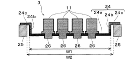
図4に示すように、ヘッドホルダ24は、第2方向Yに長尺なベースプレート24aと、このベースプレート24aの長手方向両縁部からそれぞれ上方に起立した両側の側壁部24bと、各側壁部24bの上端部から側方(ベースプレート24a側とは反対側)に延びる固定部24cとから構成される。そして、各ヘッドモジュール3は、ヘッドホルダ両側の固定部24cでモジュール取付枠25に取り付けられている。ここで、ベースプレート24aの長手方向の全長W1は、モジュール取付枠25の空部29の第2方向Yの内寸W2よりも少しだけ小さく設計されており、この空部29内にベースプレート24aが配置されるようになっている。
As shown in FIG. 4, the
ここで、上記の単位ヘッド11は、多数の部品を組み付けて構成されているため、各部品の公差が累積することにより、全体的な部品公差が大きくなる傾向にある。このため、何らの対策を施さないで各単位ヘッド11をヘッドホルダ24に単に取り付けただけでは、各単位ヘッド間でノズル開口30の相対位置がずれてしまう虞がある。その結果、記録紙4上でインクの着弾位置がずれ、これにより、記録画像等に筋が生じたりして画質が低下する可能性がある。このため、従来では、単位ヘッドを高精度に位置決めした状態でヘッドホルダに配置するアライメント作業が製造工程で行われていた。しかしながら、同一のヘッドホルダに取り付けられた複数の単位ヘッドのうち、一部の単位ヘッドにインク吐出不良などの不具合が生じた場合において該当する単位ヘッドのみを交換するとき、上記のアライメントを再調整しないと位置精度が低下してしまう虞がある。このような事情に鑑み、本発明に係るヘッドモジュール3では、単位ヘッド11を単体で交換した場合において別途アライメントを行わなくても交換前後の単位ヘッド11の位置精度の低下を抑えるようにしている。以下、この点について説明する。
Here, since the
図5は、単位ヘッド11に位置決め部38を配設する工程を説明する模式図である。位置決め部38は、上述したようにヘッドホルダ24に対する単位ヘッド11の配置位置に係わる部材であるため、単位ヘッド11に対して高い精度で位置決めした状態で配設する必要がある。このため、同図に示すように、線膨張係数が可及的に小さく、尚且つ透視性を有する(即ち、透明な)ガラスなどの板材からなるアライメント基板40を用いて単位ヘッド11に対する位置決め部38の配設位置を定める。このアライメント基板40には、ノズル開口30の位置を規定する第1のアライメントマーク41と、ノズル開口30に対する位置決め部38の相対的な位置を規定する第2のアライメントマーク42とが設けられている。これらのアライメントマーク41,42はフォトマスクを利用してスパッタリング又はエッチング等によって形成される。
FIG. 5 is a schematic diagram for explaining a process of disposing the
本実施形態における第1のアライメントマーク41は、ノズル開口30と同程度の大きさの円形のマークである。この第1のアライメントマーク41は、複数のノズル列27のうちの何れかのノズル列27の両端に位置するノズル開口30a,30bに対応してアライメント基板40に合計2つ設けられている。即ち、ノズル列27の一方の端部に位置するノズル開口30aに対応する第1のアライメントマーク41aと、ノズル列27の他方の端部に位置するノズル開口30bに対応する第2のアライメントマーク41bとがアライメント基板40に形成されている。以下、アライメントで基準となるノズル開口30a,30bを基準ノズル開口という。
なお、ノズル開口30との相対位置が高精度に規定された基準マークをノズル形成面26に形成し、アライメント基板40にはこの基準マークに対応する位置に第1のアライメントマーク41を形成する構成を採用することもできる。
The
A reference mark whose relative position with respect to the
また、本実施形態における第2のアライメントマーク42は、位置決め部38の筒状部37の外径と同程度の大きさの円とこれに外接する正方形との組み合わせから成るマークであり、2つの位置決め部38a,38bに対応して、アライメント基板40に合計2つ形成されている。即ち、ノズル列方向の一側の位置決め部38aに対応する第2のアライメントマーク42aと、ノズル列方向の他側の位置決め部38bに対応する第2のアライメントマーク42bとがアライメント基板40上に設けられている。
Further, the second alignment mark 42 in the present embodiment is a mark composed of a combination of a circle having the same size as the outer diameter of the
この第2のアライメントマーク42は、第1のアライメントマーク41に対する相対位置が高い精度で定められている。これは、アライメント基板40上にクロムなどの金属をスパッタリングで成膜し、それをフォトマスクを用いて、第1のアライメントマーク41、第2のアライメントマーク42を形成することで得られる。そして、この第1のアライメントマーク41a,41bと第2のアライメントマーク42a,42bの相対位置関係は、単位ヘッド11における基準ノズル開口30a,30bと位置決め部38a,38bの相対位置関係に対応しており、また、ヘッドホルダ24に単位ヘッド11を取り付けた状態における基準ノズル開口30a,30bと上記各ボス穴との相対位置関係にも対応している。したがって、第1のアライメントマーク41a,41bに単位ヘッド11のノズル開口30a,30bの平面上の位置を合わせた上で、第2のアライメント42a,42bに位置決め部材38a,38bの平面上の位置を合わせた状態で各位置決め部38a,38bを単位ヘッド11のフランジ部32a,32bにそれぞれ固定することで、ノズル開口30に対する位置決め部38の相対位置を高い精度で規定することが可能となる。
なお、アライメントマーク41,42の寸法や形状は例示したものには限られず、アライメントに支障がなければ任意の寸法・形状(例えば、十文字状など)のアライメントマークを採用することができる。
The second alignment mark 42 is determined with high accuracy relative to the
Note that the dimensions and shapes of the alignment marks 41 and 42 are not limited to those illustrated, and any alignment mark having an arbitrary size and shape (for example, a cross shape) can be employed as long as there is no problem in alignment.
単位ヘッド11に対する位置決め部38のアライメントは、図示しないアライメント装置において単位ヘッド11のノズル形成面26とアライメント基板40のアライメントマーク形成面とを対向配置した状態で、第1のアライメントマーク41とノズル開口30との平面上の位置を合わせるノズル位置合わせ工程と、第1のアライメントマーク41とノズル開口30の位置を合わせた状態で第2のアライメントマーク42と位置決め部38との平面上の位置を合わせた状態でフランジ部32に位置決め部38を配設(固定)する位置決め部配設工程とを経る。
The alignment of the
ノズル位置合わせ工程では、単位ヘッド11とアライメント基板40とを治具に固定し、ノズル形成面26に対してアライメント基板40を挟んで対向配置されたカメラなどの撮像手段を通じて観察しながら、単位ヘッド11とアライメント基板40の何れか一方を他方に対してX又はY方向に平行移動させながら第1のアライメントマーク41a,41bと対応するノズル開口30a,30bとの平面上の位置をそれぞれ合わせる。
In the nozzle alignment process, the
次に、位置決め部配設工程では、単位ヘッド11とアライメント基板40の相対的な位置を固定した状態で、第2のアライメントマーク42a,42bと位置決め部38a,38bの平面上の位置をそれぞれ合わせる。ここで、単位ヘッド11の先端面側に設けられたノズル形成面26に対し、位置決め部38を固定するフランジ部32の固定面は、単位ヘッド11の基端側に後退した位置に設けられている。このため、このままでは、位置決め部38と第2アライメントマーク42とが離隔した状態で位置合わせを行うことになり、位置精度が低下する虞がある。
Next, in the positioning portion disposing step, the positions of the second alignment marks 42a and 42b and the
この点に鑑み、本実施形態においては、アライメント基板40と位置決め部38との間に仲介部材44を配置してアライメントを行うことで、位置決め精度の低下を抑えている。この仲介部材44は、図5に示すように、円筒状の部材であり、位置決め部38a,38bに対応して合計2つ(44a,44b)設けられている。この仲介部材44の全長は、ノズル形成面26とアライメント基板40とを対向配置した状態におけるアライメント基板40と、フランジ部32に配置された位置決め部38との間のギャップに相当する長さに設計されている。また、仲介部材44の外径は、位置決め部38の鍔部39の外径と同程度であり、仲介部材44の内径は、位置決め部38の筒状部37の外径よりも少し大きく設計されている。したがって、仲介部材44の中心の穴に位置決め部38の筒状部37を嵌め込むことで、仲介部材44の全長方向の一端部に位置決め部38を取り付けることができるようになっている。
In view of this point, in the present embodiment, the
上記仲介部材44を用いて位置決め部38の配設工程を行う場合、まず、上記のように一端部に位置決め部38を取り付けると共に、この位置決め部38を単位ヘッド11のフランジ部32に向けた姿勢で、仲介部材44a,44bをアライメント基板40における第2のアライメントマーク42a,42bに配置する。この際、第2のアライメントマーク42に対して仲介部材44の中心の穴の位置を合わせる。これにより、第2のアライメントマーク42を基準として単位ヘッド11のフランジ部32に対する位置決め部38の配置位置を高い精度で定めることができる。そして、この状態で、位置決め部38をフランジ部32に固定する。この固定方法としては、接着やネジ留め等、種々の固定方法を採用することができる。
When performing the arrangement step of the
このようにして、アライメント基板40を利用して単位ヘッド11に位置決め部38を配設することにより、ノズル開口30に対する位置決め部38の相対位置を高い精度に設定することが可能となる。
In this manner, by arranging the
単位ヘッド11に位置決め部38を配設したならば、各単位ヘッド11をヘッドホルダ24に対して位置決めした状態で取り付ける取付工程を行う。この取付工程では、ヘッドホルダ24におけるヘッド配置領域に設けられたボス穴に、位置決め部38の筒状部37を嵌入させることで、ヘッドホルダ24に対する単位ヘッド11の配置位置が規定される。この位置決め状態で、単位ヘッド11をヘッドホルダ24に対し接着やネジ留め等で固定する。
If the
以上のように、単位ヘッド11に対し、ノズル開口30に対する相対位置が高精度で定められた位置決め部材38を配設することにより、ヘッドホルダ24に対して各単位ヘッド11を高い精度で位置決めした状態で取り付けることができる。これにより、ヘッドホルダ24において各単位ヘッド11のノズル開口30が本来望ましい位置に配置される。その結果、記録紙4等の噴射対象物に対するインクの着弾位置ずれを抑制することができ、記録画像の画質の低下を防止することが可能となる。
As described above, each
また、ヘッドモジュール2における一部の単位ヘッド11に不具合が生じた場合に、当該単位ヘッド11を交換する際、別途アライメント工程を行わなくても位置決め部38を利用して新しい単位ヘッド11をヘッドホルダ24に取り付けるだけで当該単位ヘッド11がヘッドホルダ24に対して高精度に位置決めされる。即ち、複数の単位ヘッド11から構成されるヘッドモジュールにおいて単位ヘッド単体の交換に対応することができ、交換コストを削減することが可能となる。
Further, when a problem occurs in some of the unit heads 11 in the
なお、上記実施形態においては、位置決め部38を、ヘッド本体とは別体とした構成を例示したが、これには限られない。例えば、位置決め部配設工程において、フランジ部32における第2のアライメントマーク42に対応する位置に、位置決め穴を形成することで、この位置決め穴を本発明における位置決め部として機能させることも可能である。この構成の場合、ヘッドホルダ24に位置決めボスを突設し、この位置決めボスを位置決め穴に嵌入させることで、ヘッドホルダ24に対する単位ヘッド11の配置位置が規定される。
In the above-described embodiment, the configuration in which the
また、本発明は、複数の液体噴射ヘッドから成るヘッドモジュールを備えたものであれば、液晶ディスプレー等のカラーフィルタの製造に用いられる色材噴射ヘッド、有機EL(Electro Luminescence)ディスプレー、FED(面発光ディスプレー)等の電極形成に用いられる電極材噴射ヘッド、バイオチップ(生物化学素子)の製造に用いられる生体有機物噴射ヘッド等の他の液体噴射ヘッド、及び、これを備える液体噴射装置にも適用することができる。 Moreover, if this invention is provided with the head module which consists of a some liquid ejecting head, the color material ejecting head used for manufacture of color filters, such as a liquid crystal display, an organic EL (Electro Luminescence) display, FED (surface) Applied to other liquid ejecting heads such as an electrode material ejecting head used for forming electrodes such as a light emitting display), a bioorganic material ejecting head used for manufacturing a biochip (biochemical element), and a liquid ejecting apparatus including the same. can do.
1…プリンタ,3…ヘッドモジュール,4…記録紙,11…単位ヘッド,24…ヘッドホルダ,26…ノズル形成面,30…ノズル開口,31…ヘッドケース,32…フランジ部,37…筒状部,38…位置決め部,39…鍔部,40…アライメント基板,41…第1のアライメントマーク,42…第2のアライメントマーク,44…仲介部材
DESCRIPTION OF
Claims (4)
ノズル開口の位置を規定する第1のアライメントマークと、前記ノズル開口に対する前記位置決め部の相対的な位置を規定する第2のアライメントマークとが形成され、透視性を有するアライメント基板を設け、
液体噴射ヘッドのノズル形成面と前記アライメント基板とを対向配置した状態で、前記第1のアライメントマークと前記ノズル開口との平面上の位置を合わせるノズル位置合わせ工程と、
前記第2のアライメントマークとの平面上の位置が合う液体噴射ヘッド上の位置に前記位置決め部を配設する位置決め部配設工程と、
を含むことを特徴とする液体噴射ヘッドの製造方法。 A method of manufacturing a liquid ejecting head having a nozzle opening for ejecting liquid and being attached to the head holder in a state of being positioned with respect to the head holder by a positioning unit,
A first alignment mark that defines the position of the nozzle opening and a second alignment mark that defines the relative position of the positioning portion with respect to the nozzle opening are formed, and a transparent alignment substrate is provided.
A nozzle alignment step of aligning the position of the first alignment mark and the nozzle opening on the plane in a state where the nozzle formation surface of the liquid jet head and the alignment substrate are disposed opposite to each other;
A positioning portion disposing step of disposing the positioning portion at a position on the liquid ejecting head that matches a position on the plane with the second alignment mark;
A method of manufacturing a liquid ejecting head, comprising:
前記ノズル形成面と前記アライメント基板とを対向配置した状態における前記アライメント基板と前記固定面上の前記位置決め部との間のギャップに相当する全長の仲介部材を設け、
前記位置決め部配設工程では、前記仲介部材と前記第2のアライメントマークとの平面上の位置を合わせ、当該位置決めされた仲介部材との平面上の位置が合う前記固定面上の位置に前記位置決め部を配設することを特徴とする請求項1に記載の液体噴射ヘッドの製造方法。 In the case of disposing the positioning portion on a fixed surface provided at a position retracted toward the head base end side with respect to the nozzle forming surface on the head front end side in the liquid ejecting head,
A mediating member having a full length corresponding to a gap between the alignment substrate and the positioning portion on the fixed surface in a state in which the nozzle forming surface and the alignment substrate are arranged to face each other,
In the positioning portion disposing step, the position on the plane of the mediating member and the second alignment mark is aligned, and the positioning is performed at a position on the fixed surface where the position on the plane of the positioned mediating member matches. The method of manufacturing a liquid jet head according to claim 1, wherein a portion is provided.
ノズル開口の位置を規定する第1のアライメントマークと、前記ノズル開口に対する前記位置決め部の相対的な位置を規定する第2のアライメントマークとが形成され、透視性を有するアライメント基板を設け、
液体噴射ヘッドのノズル形成面と前記アライメント基板とを対向配置した状態で、前記第1のアライメントマークと前記ノズル開口との平面上の位置を合わせるノズル位置合わせ工程と、
前記第2のアライメントマークとの平面上の位置が合う液体噴射ヘッド上の位置に前記位置決め部を配設する位置決め部配設工程と、
前記液体噴射ヘッドを、前記位置決め部によって前記ヘッドホルダに対して位置決めした状態で該ヘッドホルダに取り付ける取付工程と、
を含むことを特徴とする液体噴射ヘッドモジュールの製造方法。 A method of manufacturing a liquid ejecting head module in which a plurality of liquid ejecting heads having nozzle openings for ejecting liquid are attached to a head holder in a state where the liquid ejecting head is positioned with respect to the head holder by a positioning portion provided in the liquid ejecting head. And
A first alignment mark that defines the position of the nozzle opening and a second alignment mark that defines the relative position of the positioning portion with respect to the nozzle opening are formed, and a transparent alignment substrate is provided.
A nozzle alignment step of aligning the position of the first alignment mark and the nozzle opening on the plane in a state where the nozzle formation surface of the liquid jet head and the alignment substrate are disposed opposite to each other;
A positioning portion disposing step of disposing the positioning portion at a position on the liquid ejecting head that matches a position on the plane with the second alignment mark;
An attachment step of attaching the liquid jet head to the head holder in a state of being positioned with respect to the head holder by the positioning portion;
A method of manufacturing a liquid ejecting head module, comprising:
前記ノズル形成面と前記アライメント基板とを対向配置した状態における前記アライメント基板と前記固定面上の前記位置決め部との間のギャップに相当する全長の仲介部材を設け、
前記位置決め部配設工程では、前記仲介部材と前記第2のアライメントマークとの平面上の位置を合わせ、当該位置決めされた仲介部材との平面上の位置が合う前記固定面上の位置に前記位置決め部を配設することを特徴とする請求項3に記載の液体噴射ヘッドモジュールの製造方法。 In the case of disposing the positioning portion on a fixed surface provided at a position retracted toward the head base end side with respect to the nozzle forming surface on the head front end side in the liquid ejecting head,
A mediating member having a full length corresponding to a gap between the alignment substrate and the positioning portion on the fixed surface in a state in which the nozzle forming surface and the alignment substrate are arranged to face each other,
In the positioning portion disposing step, the position on the plane of the mediating member and the second alignment mark is aligned, and the positioning is performed at a position on the fixed surface where the position on the plane of the positioned mediating member matches. The method of manufacturing a liquid jet head module according to claim 3, wherein a portion is provided.
Priority Applications (1)
| Application Number | Priority Date | Filing Date | Title |
|---|---|---|---|
| JP2008184456A JP2010023259A (en) | 2008-07-16 | 2008-07-16 | Manufacturing method for liquid jetting head, and manufacturing method for liquid jetting head module |
Applications Claiming Priority (1)
| Application Number | Priority Date | Filing Date | Title |
|---|---|---|---|
| JP2008184456A JP2010023259A (en) | 2008-07-16 | 2008-07-16 | Manufacturing method for liquid jetting head, and manufacturing method for liquid jetting head module |
Publications (2)
| Publication Number | Publication Date |
|---|---|
| JP2010023259A true JP2010023259A (en) | 2010-02-04 |
| JP2010023259A5 JP2010023259A5 (en) | 2011-05-26 |
Family
ID=41729563
Family Applications (1)
| Application Number | Title | Priority Date | Filing Date |
|---|---|---|---|
| JP2008184456A Withdrawn JP2010023259A (en) | 2008-07-16 | 2008-07-16 | Manufacturing method for liquid jetting head, and manufacturing method for liquid jetting head module |
Country Status (1)
| Country | Link |
|---|---|
| JP (1) | JP2010023259A (en) |
Cited By (1)
| Publication number | Priority date | Publication date | Assignee | Title |
|---|---|---|---|---|
| CN103935122A (en) * | 2013-01-17 | 2014-07-23 | 三星显示有限公司 | Printing Apparatus |
-
2008
- 2008-07-16 JP JP2008184456A patent/JP2010023259A/en not_active Withdrawn
Cited By (1)
| Publication number | Priority date | Publication date | Assignee | Title |
|---|---|---|---|---|
| CN103935122A (en) * | 2013-01-17 | 2014-07-23 | 三星显示有限公司 | Printing Apparatus |
Similar Documents
| Publication | Publication Date | Title |
|---|---|---|
| JP5423019B2 (en) | Liquid discharge head unit and image forming apparatus | |
| JP6028371B2 (en) | Liquid ejecting head unit and liquid ejecting apparatus | |
| US20100026752A1 (en) | Method of manufacturing liquid ejecting head and liquid ejecting apparatus | |
| JP2009006603A (en) | Piezoelectric actuator and its manufacturing method, liquid discharge head, and image forming apparatus | |
| JP4729957B2 (en) | Droplet discharge head bar, droplet discharge apparatus, and droplet discharge head bar manufacturing method | |
| JP5338222B2 (en) | Liquid ejector | |
| JP2015136866A (en) | Liquid ejection head unit and liquid ejection device | |
| JP6146081B2 (en) | Liquid ejecting head, liquid ejecting head unit, liquid ejecting apparatus, and method of manufacturing liquid ejecting head unit | |
| JP2010069627A (en) | Liquid jet head positioning method and liquid jet head module | |
| US8393708B2 (en) | Recording device, method of positioning recording head, and method of manufacturing recording device | |
| JP2009214510A (en) | Liquid jet head and liquid jet apparatus | |
| JP5751313B2 (en) | Liquid discharge head unit and image forming apparatus | |
| JP2010069628A (en) | Liquid jet head mounting method | |
| JP2010023259A (en) | Manufacturing method for liquid jetting head, and manufacturing method for liquid jetting head module | |
| JP5316301B2 (en) | Method for manufacturing liquid jet head | |
| JP5304039B2 (en) | Liquid ejector | |
| JP2010030069A (en) | Liquid jet head module, and method of manufacturing liquid jet head module | |
| JP2009297902A (en) | Liquid jet apparatus | |
| JP6131527B2 (en) | Manufacturing method of liquid jet head unit | |
| JP4935994B2 (en) | Liquid ejecting head unit and liquid ejecting apparatus | |
| JP2010042625A (en) | Liquid jet head module and method for manufacturing liquid jet head module | |
| JP2010058359A (en) | Method of manufacturing liquid jet head | |
| JP2010069651A (en) | Liquid jet head mounting adjusting device and liquid jet head mounting adjusting method | |
| JP6341653B2 (en) | Liquid ejecting head manufacturing method, liquid ejecting head, and liquid ejecting apparatus | |
| JP5333026B2 (en) | Method for manufacturing liquid jet head |
Legal Events
| Date | Code | Title | Description |
|---|---|---|---|
| A521 | Written amendment |
Effective date: 20110408 Free format text: JAPANESE INTERMEDIATE CODE: A523 |
|
| A621 | Written request for application examination |
Effective date: 20110408 Free format text: JAPANESE INTERMEDIATE CODE: A621 |
|
| A761 | Written withdrawal of application |
Effective date: 20111219 Free format text: JAPANESE INTERMEDIATE CODE: A761 |