JP2010023189A - Reciprocating working tool - Google Patents
Reciprocating working toolInfo
- Publication number
- JP2010023189A JP2010023189A JP2008187846A JP2008187846A JP2010023189A JP 2010023189 A JP2010023189 A JP 2010023189A JP 2008187846 A JP2008187846 A JP 2008187846A JP 2008187846 A JP2008187846 A JP 2008187846A JP 2010023189 A JP2010023189 A JP 2010023189A
- Authority
- JP
- Japan
- Prior art keywords
- bevel gear
- counterweight
- axis direction
- work tool
- crank
- Prior art date
- Legal status (The legal status is an assumption and is not a legal conclusion. Google has not performed a legal analysis and makes no representation as to the accuracy of the status listed.)
- Granted
Links
- 230000033001 locomotion Effects 0.000 claims abstract description 56
- 238000000034 method Methods 0.000 claims description 8
- 238000000465 moulding Methods 0.000 claims description 2
- 230000009467 reduction Effects 0.000 abstract description 7
- 230000007246 mechanism Effects 0.000 description 17
- 238000005520 cutting process Methods 0.000 description 11
- 238000006243 chemical reaction Methods 0.000 description 4
- 230000008859 change Effects 0.000 description 3
- 230000003111 delayed effect Effects 0.000 description 3
- 239000000463 material Substances 0.000 description 3
- 238000010586 diagram Methods 0.000 description 2
- 238000003754 machining Methods 0.000 description 2
- 230000004048 modification Effects 0.000 description 2
- 238000012986 modification Methods 0.000 description 2
- 230000005540 biological transmission Effects 0.000 description 1
- 239000000470 constituent Substances 0.000 description 1
- 238000007796 conventional method Methods 0.000 description 1
- 230000000694 effects Effects 0.000 description 1
- 230000005484 gravity Effects 0.000 description 1
- 230000006872 improvement Effects 0.000 description 1
- 230000008569 process Effects 0.000 description 1
- 238000011112 process operation Methods 0.000 description 1
- 238000000926 separation method Methods 0.000 description 1
- 238000005245 sintering Methods 0.000 description 1
Images


Abstract
Description
本発明は、例えばレシプロソーやジグソー等のように先端工具が往復運動して被加工材の切断作業を行なう往復動式作業工具の防振技術に関する。 The present invention relates to a vibration isolating technique for a reciprocating work tool such as a reciprocating saw or a jigsaw in which a tip tool reciprocates to cut a workpiece.
特開2005−14111号公報(特許文献1)には、レシプロソーの構成が記載されている。この先行技術に係るレシプロソーは、先端工具が取付けられたスライダをモータによりクランクを介して往復運動させることで先端工具による切断作業を行なう際、スライダと対向して直線往復運動を行なうカウンタウェイトを備えている。すなわち、カウンタウェイトをスライドと逆向きに直線動作させ、これによりスライダが往復運動する際に発生する振動の低減を図っている。 Japanese Patent Laying-Open No. 2005-14111 (Patent Document 1) describes the configuration of a reciprocating saw. This reciprocating saw according to the prior art includes a counterweight that performs a linear reciprocating motion opposite to the slider when the cutting tool is reciprocated through a crank by means of a motor to reciprocate the slider to which the tip tool is attached. ing. That is, the counterweight is moved linearly in the direction opposite to the slide, thereby reducing the vibration generated when the slider reciprocates.
スライダの直線往復運動と逆位相でカウンタウェイトを往復運動させるレシプロソーの振動低減方式によれば、スライダの長軸方向に関し、スライダとカウンタウェイトとの間で慣性力を主体とする運動量を相殺できるため、合理的な振動の低減が可能となる。しかしながら、カウンタウェイトが運動方向を転換する際の衝突による振動が発生し、また運動方向転換によるエネルギーロスが生ずるという点で、なお改良の余地がある。
本発明は、かかる点に鑑みてなされたものであり、往復動式作業工具において、直線往復運動を伴わず円滑に作動するカウンタウェイトによる振動低減技術を提供することを目的とする。 The present invention has been made in view of this point, and an object of the present invention is to provide a vibration reduction technique using a counterweight that operates smoothly without a linear reciprocating motion in a reciprocating work tool.
上記課題を達成するため、本発明に係る往復動式作業工具の好ましい形態は、先端工具を長軸方向に往復動させて被加工材に所定の加工作業を遂行する往復動式作業工具において、先端工具の長軸方向と平行に配置されたモータの出力軸と、出力軸に設けられたピニオンと、ピニオンと噛み合い係合され、先端工具の長軸方向と交差する軸線回りに回転駆動される第1ベベルギアと、第1ベベルギアが固定され、当該第1ベベルギアの回転運動を直線運動に変換するクランクと、先端工具を保持するとともにクランクの直線運動を介して先端工具の長軸方向に直線状に往復駆動されるスライダとを有する。本発明における「往復動式作業工具」としては、木工、金工、石工等といった各種被加工材の加工作業に用いられる作業工具が包含され、さらに被加工材の切断作業に用いられるレシプロソー、あるいはジグソー等の各種作業工具が広く包含される。また、本発明における「クランク」は、典型的には、第1ベベルギアが固定される回転軸、当該回転軸の回転軸線から所定距離だけ偏心した位置に配置される偏心ピン、回転軸と偏心ピンとを互いに接合するクランク板を有して構成される。 In order to achieve the above object, a preferred embodiment of a reciprocating work tool according to the present invention is a reciprocating work tool that performs a predetermined machining operation on a workpiece by reciprocating a tip tool in a long axis direction. An output shaft of a motor arranged in parallel to the long axis direction of the tip tool, a pinion provided on the output shaft, meshingly engaged with the pinion, and driven to rotate about an axis intersecting the long axis direction of the tip tool A first bevel gear, a crank that is fixed to the first bevel gear, and that converts the rotational motion of the first bevel gear to linear motion, and that holds the tip tool and is linear in the longitudinal direction of the tip tool via the crank's linear motion And a slider that is driven back and forth. The “reciprocating work tool” in the present invention includes work tools used for various work materials such as woodwork, metalwork, masonry, etc., and reciprocating saws or jigsaws used for cutting work materials. Etc. are widely included. The “crank” in the present invention typically includes a rotating shaft to which the first bevel gear is fixed, an eccentric pin disposed at a position deviated by a predetermined distance from the rotating axis of the rotating shaft, a rotating shaft and an eccentric pin. Are configured to have crank plates that join each other.
本発明に係る往復動式作業工具の好ましい形態によれば、特徴的構成として、第1ベベルギアの回転軸線と同軸上で第1ベベルギアに対向状に配置されてピニオンと噛み合い係合され、第1ベベルギアとは反対方向に回転駆動される第2ベベルギアと、第1ベベルギアの回転軸線から所定距離だけ偏心した位置に配置されるとともに、当該第1ベベルギアと一体に回転する第1カウンタウェイトと、第2ベベルギアの回転軸線から所定距離だけ偏心した位置に配置されるとともに、当該第2ベベルギアと一体に回転する第2カウンタウェイトとを更に有する。そして、第1カウンタウェイト及び第2カウンタウェイトは、第1ベベルギアの回転軸線回りを公転運動する際、先端工具の長軸方向成分がスライダの直線運動に対して対向動作するように設定されるとともに、更には先端工具の長軸方向に関しては互いに同位相となり、先端工具の長軸方向と交差する方向に関しては当該長軸線を挟んで互いに等距離で対向するように構成された第1カウンタウェイト及び第2カウンタウェイトである。 According to a preferred embodiment of the reciprocating work tool according to the present invention, as a characteristic configuration, the first bevel gear is disposed coaxially with the rotation axis of the first bevel gear so as to be opposed to the first bevel gear and engaged with the pinion. A second bevel gear that is rotationally driven in a direction opposite to the bevel gear, a first counterweight that is disposed at a position eccentric from the rotation axis of the first bevel gear by a predetermined distance, and that rotates integrally with the first bevel gear; The second bevel gear further includes a second counterweight that is disposed at a position eccentric from the rotation axis of the two bevel gear by a predetermined distance and that rotates together with the second bevel gear. The first counterweight and the second counterweight are set so that the component in the long axis direction of the tip tool opposes the linear motion of the slider when revolving around the rotation axis of the first bevel gear. Further, a first counterweight configured to be in phase with each other with respect to the major axis direction of the tip tool, and to face each other at an equal distance across the major axis with respect to a direction intersecting with the major axis direction of the tip tool; This is the second counter weight.
なお、本発明における「第1ベベルギアと一体に回転する第1カウンタウェイト」としては、当該第1カウンタウェイトが第1ベベルギアに設けられる態様、あるいは第1ベベルギアと一体に回転するクランクに設けられる態様のいずれも好適に包含する。また、本発明における「第1カウンタウェイト」は、別部材として形成したものを第1ベベルギアまたはクランクに取付ける態様、あるいは第1ベベルギアまたはクランクに対して一体に形成する態様のいずれも好適に包含する。同様に本発明における「第2カウンタウェイト」は、別部材として形成したものを第2ベベルギアに取付ける態様、あるいは第2ベベルギアに対して一体に形成する態様のいずれも好適に包含する。 In the present invention, the “first counter weight rotating integrally with the first bevel gear” is an aspect in which the first counter weight is provided in the first bevel gear, or an aspect in which the first counter weight is provided in the crank rotating integrally with the first bevel gear. Any of these are preferably included. In addition, the “first counterweight” in the present invention suitably includes either an aspect in which a separate member is attached to the first bevel gear or the crank, or an aspect in which the first counterweight is integrally formed with the first bevel gear or the crank. . Similarly, the “second counterweight” in the present invention suitably includes both an aspect in which a separate member is attached to the second bevel gear, or an aspect in which the second counterweight is integrally formed with the second bevel gear.
本発明によれば、第1カウンタウェイトと第2カウンタウェイトがクランクの回転軸線回りの公転運動(円運動)を行う際の先端工具長軸方向成分(先端工具の長軸方向を水平とした場合の前後方向成分)の運動量が、スライダの直線運動量に対向し、これにより当該スライダの直線往復運動で生ずる振動を低減することができる。一方、先端工具長軸方向と交差する方向(先端工具の長軸方向を水平とした場合の左右方向)については、互いに反対方向に回転する第1カウンタウェイトと第2カウンタウェイトの運動量が互いに相殺され、無用な振動が発生しない。 According to the present invention, when the first counterweight and the second counterweight perform the revolving motion (circular motion) around the rotation axis of the crank, the tip tool long axis direction component (when the long axis direction of the tip tool is horizontal) The momentum of the forward and backward direction component) opposes the linear momentum of the slider, thereby reducing the vibration caused by the linear reciprocating motion of the slider. On the other hand, the momentum of the first counterweight and the second counterweight rotating in the opposite directions cancel each other in the direction intersecting the tip tool major axis direction (left and right direction when the tool tool major axis direction is horizontal). And unnecessary vibrations do not occur.
このように、本発明によれば、第1及び第2カウンタウェイトの回転運動を利用した円滑な作動による振動の低減が可能とされる。これによりカウンタウェイトが直線往復運動することで振動の低減を行なう従来方式とは異なり、カウンタウェイトが運動方向を転換する際の衝突による振動の発生、あるいは運動方向転換によるエネルギーロスの発生等の問題が解消される。 As described above, according to the present invention, it is possible to reduce vibrations by smooth operation using the rotational motion of the first and second counterweights. Unlike conventional methods that reduce vibration by counter reciprocating movement of the counterweight, problems such as generation of vibration due to collision when the counterweight changes the direction of movement, or generation of energy loss due to change of movement direction, etc. Is resolved.
本発明に係る往復動式作業工具の更なる形態によれば、第1ベベルギアの歯と第2ベベルギアの歯は、歯数が同一である。このような構成とすることで、第1ベベルギア及び第2ベベルギアを介して第1及び第2カウンタウェイトにクランクの回転軸線回りの公転運動(円運動)を行なわせる場合において、当該第1及び第2カウンタウェイト相互間の動作タイミングにずれのない簡素な構成のカウンタウェイト機構を合理的に構築することができる。 According to the further form of the reciprocating work tool according to the present invention, the teeth of the first bevel gear and the teeth of the second bevel gear have the same number of teeth. By adopting such a configuration, when the first and second counterweights perform the revolving motion (circular motion) around the rotation axis of the crank via the first bevel gear and the second bevel gear, the first and second It is possible to rationally construct a counter weight mechanism having a simple configuration with no deviation in operation timing between the two counter weights.
本発明に係る往復動式作業工具の更なる形態によれば、第1ベベルギアと第2ベベルギアは、それぞれ異なる成形方法によって形成されている。スライダの駆動に用いられる第1ベベルギアは、第2カウンタウェイトの駆動に用いられる第2ベベルギアよりも大きい負荷を受けることになる。このため、第1ベベルギアについては、強度の高い材料を用いて製造する、例えば削り出しによって形成し、他方、第1ベベルギアに比べて負荷の小さい第2ベベルギアについては、安価で簡易に製造することが可能な、例えば焼結成形方法等で成形することが好適であり、これにより、両ベベルギアの耐久性を同程度となるように設定することができる。 According to the further form of the reciprocating work tool according to the present invention, the first bevel gear and the second bevel gear are formed by different molding methods. The first bevel gear used for driving the slider receives a larger load than the second bevel gear used for driving the second counterweight. For this reason, the first bevel gear is manufactured using a material having high strength, for example, formed by cutting, while the second bevel gear having a smaller load than the first bevel gear is inexpensive and easily manufactured. For example, it is preferable to form by a sintering method, and the durability of both bevel gears can be set to be approximately the same.
本発明に係る往復動式作業工具の更なる形態によれば、クランクは、第1ベベルギアと一体に回転する回転軸と、当該回転軸の回転軸線から所定距離だけ偏心した位置に配置された偏心ピンと、回転軸の長軸方向一端部に設けられ、当該回転軸と偏心ピンとを互いに接合するクランク板を有する。そして、クランク板には、第1カウンタウェイトが取付けられ、また回転軸のクランク板側には、第2ベベルギアが配置されるとともに、当該第2ベベルギアの第1カウンタウェイトとの対向面側に第2カウンタウェイトが配置された構成とされる。かかる構成によれば、第1カウンタウェイトと第2カウンタウェイトをクランクの回転軸線方向に関して互いに近接した配置が可能とされる。これにより、クランクの長軸線方向と交差する方向に関する偶アンバランスが低減し、不要な振動発生を抑制する上で有効となる。 According to the further form of the reciprocating work tool according to the present invention, the crank is a rotation shaft that rotates integrally with the first bevel gear, and an eccentricity that is arranged at a position that is eccentric from the rotation axis of the rotation shaft by a predetermined distance. A pin and a crank plate that is provided at one end in the longitudinal direction of the rotating shaft and joins the rotating shaft and the eccentric pin to each other. A first counterweight is attached to the crank plate, and a second bevel gear is disposed on the crank plate side of the rotating shaft, and the second bevel gear has a first counterweight facing the first counterweight. Two counter weights are arranged. According to such a configuration, the first counterweight and the second counterweight can be disposed close to each other in the direction of the rotation axis of the crank. As a result, even imbalance in the direction intersecting with the long axis direction of the crank is reduced, which is effective in suppressing unnecessary vibration.
本発明に係る往復動式作業工具の更なる形態によれば、第1カウンタウェイトは、偏心ピンに嵌合されるとともに、当該嵌合部から離れた位置でクランク板に止着されている。このような構成を採用することで、偏心ピンをカウンタウェイトのクランク板に対する回り止め部材として合理的に利用できる。 According to the further form of the reciprocating work tool according to the present invention, the first counterweight is fitted to the eccentric pin and fixed to the crank plate at a position away from the fitting portion. By adopting such a configuration, the eccentric pin can be rationally used as a detent member for the counterweight crank plate.
本発明に係る往復動式作業工具の更なる形態によれば、クランクは、第1ベベルギアと一体に回転する回転軸と、当該回転軸の回転軸線から所定距離だけ偏心した位置に配置された偏心ピンと、回転軸の長軸方向一端部に設けられ、当該回転軸と偏心ピンとを互いに接合するクランク板を有する。そして、第1ベベルギアが回転軸に固定され、当該回転軸は、第1ベベルギアを挟んで両側が軸受によって回転自在に支持されている。このような構成とすることで、加工作業時に負荷トルクが作用する第1ベベルギアにつき、これを安定的に支持し、円滑な回転運動を得ることができる。 According to the further form of the reciprocating work tool according to the present invention, the crank is a rotation shaft that rotates integrally with the first bevel gear, and an eccentricity that is arranged at a position that is eccentric from the rotation axis of the rotation shaft by a predetermined distance. A pin and a crank plate that is provided at one end in the longitudinal direction of the rotating shaft and joins the rotating shaft and the eccentric pin to each other. The first bevel gear is fixed to the rotating shaft, and the rotating shaft is rotatably supported by bearings on both sides of the first bevel gear. By setting it as such a structure, about the 1st bevel gear with which load torque acts at the time of a process operation, this can be supported stably and smooth rotation motion can be obtained.
本発明によれば、往復動式作業工具において、直線往復運動を伴わず円滑に作動するカウンタウェイトによる振動低減技術が提供されることとなった。 According to the present invention, in a reciprocating work tool, a vibration reduction technique using a counterweight that operates smoothly without a linear reciprocating motion is provided.
(本発明の第1の実施形態)
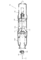
以下、本発明の実施形態につき、図1〜図5を参照しつつ詳細に説明する。本発明の実施形態は、往復動式作業工具の一例としてレシプロソーを用いて説明する。図1は本実施形態に係るレシプロソー101の全体構成を示す平断面図である。図2及び図3はレシプロソー101の全体構成を示す縦断面図であり、図2はスライダ107が前進端(図示左側)へ移動された状態が示され、図3はスライダ107が後退端(図示右側)へ移動された状態が示される。図4は本発明の主要部構成を示す拡大断面図であり、図5はカウンタウェイト143,145の動作説明図である。
(First embodiment of the present invention)
Hereinafter, embodiments of the present invention will be described in detail with reference to FIGS. The embodiment of the present invention will be described using a reciprocating saw as an example of a reciprocating work tool. FIG. 1 is a cross-sectional plan view showing the overall configuration of a
本実施の形態に係るレシプロソー101は、図1〜図3に示すように、概括的に見てレシプロソー101の外郭を構成する作業工具本体としての本体部103、当該本体部103から突出するスライダ107先端のチャック109に着脱自在に取り付けられて被加工材(便宜上特に図示しない)を切断作業するブレード111、本体部103におけるブレード111と反対側の後端部に一体状に形成されたハンドグリップ105を主体として構成されている。ブレード111は本発明における「先端工具」に対応する。
As shown in FIGS. 1 to 3, the
本体部103は、駆動モータ113を収容するモータハウジング103aと、駆動モータ113の回転出力を直線運動に変換してスライダ107に伝達する運動変換機構121を収容するギアハウジング103bによって構成されている。なお、説明の便宜上、ブレード111側(図1〜図3において左側)を前側、ハンドグリップ105側(図1〜図3において右側)を後側という。
The
モータハウジング103a内には、駆動モータ113が配設されている。駆動モータ113は、ハンドグリップ105に配置されたトリガ115が作業者により引き操作されて電気スイッチ115aがオン状態へと動作されることによって通電駆動される。駆動モータ113の通電駆動によりブレード111がスライダ107及びチャック109とともに長軸方向(前後方向)に直線状に往復運動し、被加工材を切断可能に構成される。
A
スライダ107は、ギアハウジング103bの内部空間における、ブレード111の長軸方向を水平方向としたときの上方領域に配置され、前後の軸受108a,108bを介して長軸方向(ブレード111の長軸方向)に往復動可能に支持されるとともに、ギアハウジング103b内の運動変換機構121を介してモータ軸117と接続されている。駆動モータ113は、ブレード111の長軸線の延長線の概ね真下において、モータ軸117の長軸方向がブレード111の長軸方向と平行となるように配置されている。駆動モータ113は、本発明における「モータ」に対応し、モータ軸117は、本発明における「出力軸」に対応する。
The
運動変換機構121は、モータ軸117の回転運動をスライダ107の長軸方向への直線往復運動に変換する作動機構であり、ギアハウジング103bの内部空間における、ブレード111の長軸方向を水平方向としたときの下方領域、すなわちスライダ107の概ね真下に配置されている。運動変換機構121は、水平面内で回転する駆動ベベルギア123、クランク129、スライダブロック131を主体として構成されている。駆動ベベルギア123は、本発明における「第1ベベルギア」に対応する。
The
クランク129は、ブレード111の長軸方向と交差する上下方向に延在するクランク軸129a、当該クランク軸129aの長軸方向の一端(上端)に一体に形成されたクランク板129b、及び当該クランク板129bの上面にその回転中心から所定距離だけ偏心した位置に設けられた偏心ピン129cによって構成されている。クランク軸129aは、本発明における「回転軸」に対応する。クランク軸129aは、スライダ107の概ね真下に配置されるとともに、ギアハウジング103bに上下の軸受127a,127bを介して回転自在に支持された両持ち構造として構成されている。
The
駆動ベベルギア123は、クランク軸129aの上部側(スライダ107側)に固定されるとともに、下側面部に形成された歯がモータ軸117の先端に形成されたピニオン119と噛み合い係合され、これによりクランク軸129aと共に水平面内での回転が可能とされる。偏心ピン129cは、下端側が駆動ベベルギア123に形成されたピン取付孔に上方から圧入固定されており、上端側がスライダ107の下面側に形成されたスライダブロック131のガイド溝131aに軸受133を介して下方から上向きに嵌入されている。スライダブロック131のガイド溝131aは、スライダ107の長軸方向と交差する水平方向、すなわち左右方向に延びており、当該ガイド溝131aに沿って軸受133と共に偏心ピン129cが相対的に移動可能とされている。
The
従って、駆動モータ113が通電駆動されると、モータ軸117の回転出力は、ピニオン119と噛み合い係合する駆動ベベルギア123を介してクランク軸129aへと伝達される。そして、当該クランク軸129aが回転駆動されると、偏心ピン129cがクランク軸129aの回転軸線回りに公転運動(円運動)し、当該公転運動のうち、スライダ107の長軸方向と水平面内で交差する左右方向の動作成分については、ガイド溝131aに逃がされ、スライダ107の長軸方向への動作成分のみが当該スライダ107に伝達される。これによりスライダ107は、前後方向にのみ直線状に往復運動される。なお、本体部103の先端部には切断作業時において、作業者がハンドグリップ105を把持した状態で被加工材に向って押し付けるシュー106が設けられている。
Therefore, when the
レシプロソー101には、スライダ107が直線往復運動することで発生する長軸方向の振動を低減するべくカウンタウェイト機構141が搭載される。次に当該カウンタウェイト機構141につき説明する。本実施の形態に係るカウンタウェイト機構141は、水平面内において、クランク軸129aの回転軸線回りを互いに反対方向に公転運動(円運動)を行なう2つのカウンタウェイト143,145を主体として構成される。1つのカウンタウェイト143は、駆動ベベルギア123の上側面部に取付けられ、他の1つのカウンタウェイト145は、駆動ベベルギア123と対向して配置される逆転ベベルギア147の下側面部に取付けられている。逆転ベベルギア147は、本発明における「第2ベベルギア」に対応する。駆動ベベルギア123に取付けられた駆動側カウンタウェイト143は、本発明における「第1カウンタウェイト」に対応し、逆転ベベルギア147に取付けられた逆転側カウンタウェイト145は、本発明における「第2カウンタウェイト」に対応する。すなわち、カウンタウェイト機構141は、2つのカウンタウェイト143,145と、それを駆動する2つのベベルギア123,147によって構成される。
A
ピニオン119(モータ軸117)を挟んで駆動ベベルギア123と対向して配置される逆転ベベルギア147は、クランク軸129aの下部側に軸受149を介して相対回転自在に取付けられるとともに、上側面部に形成された歯がモータ軸117のピニオン119に噛み合い係合されている。駆動ベベルギア123の上側面部には、当該駆動ベベルギア123の回転軸線から所定距離だけ偏心した位置に駆動側カウンタウェイト143が固定され、逆転ベベルギア147の下側面部には、当該逆転ベベルギア147の回転軸線から所定距離だけ偏心した位置に逆転側カウンタウェイト145が固定されており、これら駆動側及び逆転側カウンタウェイト143,145は、重量及び形状が同一に形成されるとともに、その重心から両ベベルギア123,147の回転軸線、すなわちクランク軸129aの回転軸線までの離間距離が互いに同一に設定されている。
A reverse
本実施の形態においては、対向状に配置される駆動ベベルギア123と逆転ベベルギア147が、ピニオン119を共通部品として使用する構成であり、このため、歯に関する仕様が同一に設定されている。駆動ベベルギア123と逆転ベベルギア147の歯数につき、これを同数とすることで、両ベベルギア123,147の減速比が同一に定められている。これにより駆動ベベルギア123と逆転ベベルギア147は、同軸上で互いに反対方向に同一速度で回転される構成とされる。このため、駆動側カウンタウェイト143と逆転側カウンタウェイト145が公転運動する場合における、両カウンタウェイト143,145相互間の動作タイミングにずれが生じない。更には駆動ベベルギア123と逆転ベベルギア147に関する仕様としての、モジュール、ピッチ円直径についても相互に同一に設定し、これによりピニオン119に対する噛み合い係合が共に同一条件となり、駆動ベベルギア123と逆転ベベルギア147の耐久性を同程度にすることが可能となる。
In the present embodiment, the
本実施の形態に係るカウンタウェイト機構141は、上記のように構成されている。従って、駆動ベベルギア123に取付けられた駆動側カウンタウェイト143と逆転ベベルギア147に取付けられた逆転側のカウンタウェイト145は、駆動モータ113が通電駆動され、ピニオン119を介して駆動ベベルギア123及び逆転ベベルギア147が回転駆動されるとき、クランク軸129aの回転軸線回りを互いに反対方向に公転運動(円運動)する。
The
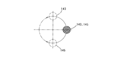
スライダ107の往復運動と、駆動側及び逆転側のカウンタウェイト143,145の公転運動に関し、レシプロソー101の前方側(先端側)へ最も移動した位置を下死点、レシプロソー101の後方(奥側)へ最も移動した位置を上死点と定義する。本実施の形態においては、スライダ107が下死点に移動されたとき、駆動側カウンタウェイト143と逆転側カウンタウェイト145が共に上死点に移動され(図2及び図4参照)、スライダ107が上死点に移動されたとき、駆動側カウンタウェイト143と逆転側カウンタウェイト145が共に下死点に移動されるように設定されている(図3参照)。
Regarding the reciprocating motion of the
従って、スライダ107が、例えば下死点から上死点へと移動するとき、駆動側カウンタウェイト143と逆転側カウンタウェイト145は、図5に矢印で示すように、共に上死点から下死点へと公転運動する。そして、駆動側及び逆転側のカウンタウェイト143,145の公転運動のうち、ブレード111の長軸方向成分の運動量がスライダ107の運動量に対しこれを相殺するように作用する。これにより、スライダ107が直線往復運動することで生ずる長軸方向、すなわち前後方向の振動を低減化することができる。このとき、駆動側及び逆転側のカウンタウェイト143,145のブレード長軸方向成分の各運動量は、互いに併合してスライダ107の運動量に対向することになる。なお、図5では駆動側カウンタウェイト143と逆転側第2カウンタウェイト145が共に上死点に置かれた状態を実線で示している。
Accordingly, when the
また、駆動側カウンタウェイト143と逆転側カウンタウェイト145は、図5に示すように、互いに反対方向に公転運動する。従って、公転運動する駆動側カウンタウェイト143と逆転側第2カウンタウェイト145の左右方向成分の運動量は、大きさが同じで反対向きとなる。このため、左右方向については、駆動側カウンタウェイト143と逆転側第2カウンタウェイト145の運動量が互いに相殺され、無用な振動の発生を抑えることが可能となる。
Further, the drive-
(本発明の第2の実施形態)
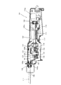
次に本発明の第2の実施形態につき、図6〜図9を参照して説明する。図6は第2の実施形態に係るレシプロソー101の全体構成を示す縦断面図であり、図7はレシプロソー101の主要部の構成を示す断面図である。図8は駆動側カウンタウェイト143の取付構造を示す平面図であり、図9は図8のA−A線断面図である。この実施の形態は、振動低減のために備えられるカウンタウェイト機構141に関する変形例であり、カウンタウェイト機構141以外については、前述した第1の実施形態と同様に構成されている。従って、第1の実施形態と同一の構成部材については、同一符号を付してその説明を省略あるいは簡略する。
(Second embodiment of the present invention)
Next, a second embodiment of the present invention will be described with reference to FIGS. FIG. 6 is a longitudinal sectional view showing the overall configuration of the reciprocating saw 101 according to the second embodiment, and FIG. 7 is a sectional view showing the configuration of the main part of the
この実施の形態では、駆動ベベルギア123がクランク軸129aの下部側に一体に回転するように取付けられ、当該駆動ベベルギア123の上側面部に形成された歯がモータ軸117のピニオン119に噛み合い係合されている。一方、逆転ベベルギア147は、クランク軸129aの上部側に軸受149を介して相対回転可能に取付けられ、その下側面部に形成された歯がモータ軸117のピニオン119に噛み合い係合されている。このように、駆動ベベルギア123と逆転ベベルギア147は、ピニオン119(モータ軸117)を挟んで対向して配置される。従って、逆転ベベルギア147は、駆動ベベルギア123に対して同軸上で反対方向に回転される。なお、駆動ベベルギア123と逆転ベベルギア147は、実施の形態と同様に、その歯数、モジュール等の歯に関する仕様が同一に設定されている。
In this embodiment, the
カウンタウェイト機構141は、駆動側カウンタウェイト143と逆転側カウンタウェイト145を有する。本実施の形態では、駆動側カウンタウェイト143は、駆動ベベルギア123と一体に回転するクランク129に取付けられている。
駆動側カウンタウェイト143の取付構造につき更に詳しく説明すると、図8及び図9に示すように、平板状のウェイト支持部材151の上面一端側に駆動側カウンタウェイト143がリベットやネジカシメ等の止着手段153により固定されている。ウェイト支持部材151は、クランク板129bの長軸方向一端面である上面に重ねられ、ネジ155により当該クランク板129bの概ね軸中心部に固定されるとともに、駆動側カウンタウェイト143の反対側に設けたピン孔151aがクランク板129b上の偏心ピン129cに対して上方から嵌合されている。かくして、駆動側カウンタウェイト143は、クランク軸129aの長軸方向上端側に対してその回転軸線から所定距離だけ偏心した位置に配置されている。
The
The
一方、逆転側カウンタウェイト145は、逆転ベベルギア147の上面側に、当該逆転ベベルギア147の回転軸線から所定距離だけ偏心した位置に取付けられている。このように、本実施の形態では、駆動側カウンタウェイト143と逆転側カウンタウェイト145は、ピニオン119(モータ出力軸117)とスライダ107との間に配置されるとともに、ウェイト支持部材151を挟んで互いに対向する近接配置構成とされる。なお、逆転側カウンタウェイト145は、少なくともウェイト支持部材151を含めた重量と回転半径の関係によって駆動側カウンタウェイト143に対して左右方向成分の運動量が互いに相殺されるように設定される。
On the other hand, the
本実施の形態に係るカウンタウェイト機構141は、上記のように構成したものであり、従って、駆動モータ113が通電駆動され、駆動ベベルギア123、クランク129を介してスライダ107が上死点と下死点との間で直線往復運動するとき、駆動側カウンタウェイト143と逆転側カウンタウェイト145は、クランク軸129aの回転軸線回りを互いに反対方向に同一速度で公転運動(円運動)する。そして、駆動側及び逆転側のカウンタウェイト143,145の公転運動のうち、ブレード111の長軸方向成分の運動量がスライダ107の運動量に対しこれを相殺するように作用し、これによりスライダ107が直線往復運動することで生ずる長軸方向、すなわち前後方向の振動を低減化することができる。
The
また、駆動側カウンタウェイト143と逆転側カウンタウェイト145は、互いに反対方向に公転運動するので、駆動側カウンタウェイト143と逆転側第2カウンタウェイト145の左右方向成分の運動量は、大きさが同じで反対向きとなる。このため、左右方向については、駆動側カウンタウェイト143と逆転側第2カウンタウェイト145の運動量が互いに相殺され、無用な振動の発生を抑えることが可能となる。このように、第2の実施形態によれば、前述した第1の実施の形態と同様の作用効果を奏する。
In addition, since the drive-
特に、この実施形態では、駆動側カウンタウェイト143と逆転側カウンタウェイト145がピニオン119とスライダ107との間において、ウェイト支持部材151を挟んで配置される構成であり、両カウンタウェイト143,145を回転軸線方向に関して互いに干渉が回避可能な僅かな距離を置いて近接して配置することが可能となる。これにより、偶アンバランスが低減される。すなわち、駆動側カウンタウェイト143と逆転側カウンタウェイト145が回転運動する際に、クランク軸129aに対して作用する当該クランク軸129aの長軸方向と交差する方向(径方向)の互いに反対向きで平行な力、すなわち偶力によるモーメントが低減されることになり、これにより不要な振動発生を抑制する上で有効となる。
In particular, in this embodiment, the drive-
また、本実施の形態では、クランク軸129aは、駆動力の伝達に用いられる駆動ベベルギア123を挟んで両側が軸受127a,127bによって支持する構成としている。このような構成とすることで、加工作業時に負荷トルクが作用する駆動ベベルギア123につき、これを安定的に支持し、円滑な回転運動を得ることができる。
In the present embodiment, the
また、本実施の形態では、ウェイト支持部材151が、ネジ155によりクランク板129bの概ね軸中心部に固定され、かつピン孔151aがクランク板129b上の偏心ピン129cに嵌合されている。すなわち、ウェイト支持部材151の取付構造につき、クランク板129b上の偏心ピン129cを回り止め部材として利用する構成としている。このため、たとえネジ155が緩んだ場合であっても駆動側カウンタウェイト143がクランク板129bと共に確実に一体となって回転される。
Further, in the present embodiment, the
次に駆動側及び逆転側カウンタウェイト143,145の駆動タイミングに関する変形例につき説明する。上述した実施の形態によれば、駆動側及び逆転側カウンタウェイト143,145は、ブレード111が取付けられたスライダ107の往復運動に対して逆位相の公転運動を行なうことで、運動量を減殺して振動を低減することができる。しかしながら、レシプロソー101にあっては、実際にブレード111を用いて被加工材を切断作業する負荷駆動状態と、切断作業に供せずにブレード111を空転状態で駆動する無負荷駆動状態とでは、ブレード111に作用する外部抵抗の有無により駆動側及び逆転側カウンタウェイト143,145による振動相殺の最適タイミングが相違することになる。負荷駆動状態では、ブレード111に切断抵抗が作用し、この切断抵抗によりブレード111を駆動するスライダ107の位相は、無負荷状態の場合に比べて遅れ側にシフトし易いからである。従って、このようなブレード111の駆動形態を考慮して駆動側及び逆転側カウンタウェイト143,145の駆動タイミングを設定することが好ましい。
Next, a modification regarding the drive timing of the drive side and reverse
そこで、上記に鑑み、ブレード111を駆動するスライダ107の往復動作と、駆動側及び逆転側カウンタウェイト143,145の公転動作の位相差が、上死点と下死点への到達タイミングが異なるように設定される。具体的には、駆動側及び逆転側カウンタウェイト143,145の公転動作の位相が、スライダ107の往復動作の位相に対して相対的に180度よりも遅れた状態となるように設定される。すなわち、スライダ107の往復動作と、駆動側及び逆転側カウンタウェイト143,145の公転動作の位相とが180度異なる逆位相の状態から見て、駆動側及び逆転側カウンタウェイト143,145の公転動作の方が遅れるように設定される。
Accordingly, in view of the above, the phase difference between the reciprocating operation of the
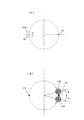
このことが図10の模式図に示される。図10の(A)がスライダ107を往復駆動するクランク129における偏心ピン129cの公転動作を示しており、図10の(B)が駆動側及び逆転側カウンタウェイト143,145の公転動作を示している。図示のように、偏心ピン129cが下死点P1にあるとき、互いに反対方向に公転動作する駆動側及び逆転側カウンタウェイト143,145は、それぞれが逆位相の状態である上死点P2に対して所定角度αだけ遅れるように設定される。そして、この遅れ角αについては、被加工材の切断作業時に頻繁に顕現する切断抵抗値を措定し、当該措定した切断抵抗値に対応する角度として定められ、例えば15度に設定される。
駆動側及び逆転側カウンタウェイト143,145の動作タイミングにつき、上記のように設定することで、切断抵抗を加味した合理的な振動低減対策が講じられる。
This is shown in the schematic diagram of FIG. 10A shows the revolution operation of the
By setting the operation timings of the driving side and reverse rotation
なお、本実施の形態では、駆動側及び逆転側のカウンタウェイト143,145を、それぞれ別部材として形成し、それを対応する部材としての駆動ベベルギア123、逆転ベベルギア147あるいはクランク129に取付ける構成としたが、駆動ベベルギア123、逆転ベベルギア147あるいはクランク129に一体に形成してもよい。
また、本実施の形態では、逆転側カウンタウェイト145を逆転ベベルギア147に直接に取付ける構成としたが、当該逆転ベベルギア147によって回転駆動される回転部材、あるいは逆転ベベルギア147と一体に回転する回転部材に逆転側カウンタウェイト145を設ける構成に変更してもよい。
また、本実施の形態は、往復動式作業工具の一例としてレシプロソー101を用いて説明したが、先端工具が往復動して被加工材を加工作業する形態、例えばジグソー等にも広く適用することが可能である。
In the present embodiment, the
In the present embodiment, the
Moreover, although this Embodiment demonstrated using the reciprocating saw 101 as an example of a reciprocating work tool, it applies widely also to the form which a tip tool reciprocates and processes a workpiece, for example, a jigsaw etc. Is possible.
101 レシプロソー(往復作動式作業工具)
103 本体部
103a モータハウジング
103b ギアハウジング
105 ハンドグリップ
106 シュー
107 スライダ
108a 前の軸受
108b 後の軸受
109 チャック
111 ブレード
113 駆動モータ
115 トリガ
115a 電気スイッチ
117 モータ軸(出力軸)
119 ピニオン
121 運動変換機構
123 駆動ベベルギア(第1ベベルギア)
127a 上の軸受
127b 下の軸受
129 クランク
129a クランク軸(回転軸)
129b クランク板
129c 偏心ピン
131 スライダブロック
131a ガイド溝
133 軸受
141 カウンタウェイト機構
143 駆動側カウンタウェイト(第1カウンタウェイト)
145 逆転側カウンタウェイト(第2カウンタウェイト)
147 逆転ベベルギア(第2ベベルギア)
149 軸受
151 ウェイト支持部
151a ピン孔
153 リベット
155 ネジ
101 Reciprocating saw (reciprocating work tool)
103 body portion 103a
119
127a Upper bearing 127b Lower bearing 129
145 Reverse counter weight (second counter weight)
147 Reversed bevel gear (second bevel gear)
149
Claims (6)
前記先端工具の長軸方向と平行に配置されたモータの出力軸と、
前記出力軸に設けられたピニオンと、
前記ピニオンと噛み合い係合され、前記先端工具の長軸方向と交差する軸線回りに回転駆動される第1ベベルギアと、
前記第1ベベルギアが固定され、当該第1ベベルギアの回転運動を直線運動に変換するクランクと、
前記先端工具を保持するとともに、前記クランクの直線運動を介して当該先端工具の長軸方向に直線状に往復駆動されるスライダと、を有し、
前記第1ベベルギアの回転軸線と同軸上で当該第1ベベルギアに対向状に配置されて前記ピニオンと噛み合い係合され、前記第1ベベルギアとは反対方向に回転駆動される第2ベベルギアと、
前記第1ベベルギアの回転軸線から所定距離だけ偏心した位置に配置されるとともに、当該第1ベベルギアと一体に回転する第1カウンタウェイトと、
前記第2ベベルギアの回転軸線から所定距離だけ偏心した位置に配置されるとともに、当該第2ベベルギアと一体に回転する第2カウンタウェイトと、を更に有し、
前記第1カウンタウェイト及び前記第2カウンタウェイトは、前記第1ベベルギアの回転軸線回りを公転運動する際、前記先端工具の長軸方向成分が前記スライダの直線運動に対して対向動作するように設定されるとともに、前記先端工具の長軸方向に関しては互いに同位相となり、前記先端工具の長軸方向と交差する方向に関しては当該長軸線を挟んで互いに等距離で対向するように構成された第1カウンタウェイト及び第2カウンタウェイトである、ことを特徴とする往復動式作業工具。 A reciprocating work tool that performs a predetermined processing operation on a workpiece by reciprocating a tip tool in a long axis direction,
An output shaft of a motor arranged in parallel with the long axis direction of the tip tool;
A pinion provided on the output shaft;
A first bevel gear meshingly engaged with the pinion and driven to rotate about an axis intersecting the longitudinal direction of the tip tool;
A crank that is fixed to the first bevel gear and converts the rotational motion of the first bevel gear to linear motion;
A slider that holds the tip tool and is driven to reciprocate linearly in the long axis direction of the tip tool through the linear motion of the crank,
A second bevel gear disposed coaxially with the rotation axis of the first bevel gear and opposed to the first bevel gear, meshingly engaged with the pinion, and driven to rotate in a direction opposite to the first bevel gear;
A first counterweight disposed at a position eccentric from the rotation axis of the first bevel gear by a predetermined distance and rotating integrally with the first bevel gear;
A second counterweight disposed at a position eccentric from the rotation axis of the second bevel gear by a predetermined distance and rotating integrally with the second bevel gear;
The first counterweight and the second counterweight are set so that the component in the long axis direction of the tip tool opposes the linear movement of the slider when revolving around the rotation axis of the first bevel gear. In addition, the first tool is configured to be in phase with each other with respect to the major axis direction of the tip tool, and to face each other at an equal distance across the major axis line with respect to the direction intersecting the major axis direction of the tip tool. A reciprocating work tool characterized by comprising a counterweight and a second counterweight.
前記第1ベベルギアの歯と第2ベベルギアの歯は、歯数が同一であることを特徴とする往復動式作業工具。 The reciprocating work tool according to claim 1,
The tooth of the first bevel gear and the tooth of the second bevel gear have the same number of teeth.
前記第1ベベルギアと前記第2ベベルギアは、それぞれ異なる成形方法によって形成されていることを特徴とする往復動式作業工具。 The reciprocating work tool according to claim 1 or 2,
A reciprocating work tool, wherein the first bevel gear and the second bevel gear are formed by different molding methods.
前記クランクは、前記第1ベベルギアと一体に回転する回転軸と、当該回転軸の回転軸線から所定距離だけ偏心した位置に配置された偏心ピンと、前記回転軸の長軸方向一端部に設けられ、当該回転軸と偏心ピンとを互いに接合するクランク板を有し、
前記クランク板には、前記第1カウンタウェイトが取付けられ、前記回転軸の前記クランク板側には前記第2ベベルギアが配置されるとともに、当該第2ベベルギアの前記第1カウンタウェイトとの対向面側に前記第2カウンタウェイトが配置されていることを特徴とする往復動式作業工具。 The reciprocating work tool according to any one of claims 1 to 3,
The crank is provided at a rotary shaft that rotates integrally with the first bevel gear, an eccentric pin that is disposed at a position that is eccentric from the rotary axis of the rotary shaft by a predetermined distance, and one end portion in the longitudinal direction of the rotary shaft, A crank plate for joining the rotary shaft and the eccentric pin to each other;
The first counter weight is attached to the crank plate, the second bevel gear is disposed on the crank plate side of the rotating shaft, and the second bevel gear is opposed to the first counter weight. The reciprocating work tool is characterized in that the second counterweight is disposed in the reciprocating work tool.
前記第1カウンタウェイトは、前記偏心ピンに嵌合されるとともに、当該嵌合部から離れた位置で前記クランク板に止着されていることを特徴とする往復動式作業工具。 The reciprocating work tool according to claim 4,
The reciprocating work tool is characterized in that the first counterweight is fitted to the eccentric pin and is fixed to the crank plate at a position away from the fitting portion.
前記クランクは、前記第1ベベルギアと一体に回転する回転軸と、当該回転軸の回転軸線から所定距離だけ偏心した位置に配置された偏心ピンと、前記回転軸の長軸方向一端部に設けられ、当該回転軸と偏心ピンとを互いに接合するクランク板を有し、
前記第1ベベルギアが前記回転軸に固定され、前記回転軸は、前記第1ベベルギアを挟んで両側が軸受によって回転自在に支持されていることを特徴とする往復動式作業工具。 A reciprocating work tool according to any one of claims 1 to 5,
The crank is provided at a rotating shaft that rotates integrally with the first bevel gear, an eccentric pin that is disposed at a position that is eccentric from the rotating axis of the rotating shaft by a predetermined distance, and one end in the longitudinal direction of the rotating shaft, A crank plate for joining the rotary shaft and the eccentric pin to each other;
A reciprocating work tool, wherein the first bevel gear is fixed to the rotating shaft, and the rotating shaft is rotatably supported by bearings on both sides of the first bevel gear.
Priority Applications (1)
| Application Number | Priority Date | Filing Date | Title |
|---|---|---|---|
| JP2008187846A JP5214357B2 (en) | 2008-07-18 | 2008-07-18 | Reciprocating work tool |
Applications Claiming Priority (1)
| Application Number | Priority Date | Filing Date | Title |
|---|---|---|---|
| JP2008187846A JP5214357B2 (en) | 2008-07-18 | 2008-07-18 | Reciprocating work tool |
Publications (2)
| Publication Number | Publication Date |
|---|---|
| JP2010023189A true JP2010023189A (en) | 2010-02-04 |
| JP5214357B2 JP5214357B2 (en) | 2013-06-19 |
Family
ID=41729507
Family Applications (1)
| Application Number | Title | Priority Date | Filing Date |
|---|---|---|---|
| JP2008187846A Active JP5214357B2 (en) | 2008-07-18 | 2008-07-18 | Reciprocating work tool |
Country Status (1)
| Country | Link |
|---|---|
| JP (1) | JP5214357B2 (en) |
Cited By (4)
| Publication number | Priority date | Publication date | Assignee | Title |
|---|---|---|---|---|
| JP2012245585A (en) * | 2011-05-27 | 2012-12-13 | Makita Corp | Cutting tool |
| WO2018221105A1 (en) * | 2017-05-31 | 2018-12-06 | 工機ホールディングス株式会社 | Reciprocating tool |
| WO2019134682A1 (en) * | 2018-01-05 | 2019-07-11 | Tti (Macao Commercial Offshore) Limited | Reciprocating saw |
| JP2019198961A (en) * | 2015-04-17 | 2019-11-21 | 株式会社マキタ | Reciprocating tool |
Citations (2)
| Publication number | Priority date | Publication date | Assignee | Title |
|---|---|---|---|---|
| JPS62144116U (en) * | 1986-03-07 | 1987-09-11 | ||
| JP2000225517A (en) * | 1998-12-04 | 2000-08-15 | Hitachi Koki Co Ltd | Reciprocating tool |
-
2008
- 2008-07-18 JP JP2008187846A patent/JP5214357B2/en active Active
Patent Citations (2)
| Publication number | Priority date | Publication date | Assignee | Title |
|---|---|---|---|---|
| JPS62144116U (en) * | 1986-03-07 | 1987-09-11 | ||
| JP2000225517A (en) * | 1998-12-04 | 2000-08-15 | Hitachi Koki Co Ltd | Reciprocating tool |
Cited By (8)
| Publication number | Priority date | Publication date | Assignee | Title |
|---|---|---|---|---|
| JP2012245585A (en) * | 2011-05-27 | 2012-12-13 | Makita Corp | Cutting tool |
| JP2019198961A (en) * | 2015-04-17 | 2019-11-21 | 株式会社マキタ | Reciprocating tool |
| WO2018221105A1 (en) * | 2017-05-31 | 2018-12-06 | 工機ホールディングス株式会社 | Reciprocating tool |
| CN110709202A (en) * | 2017-05-31 | 2020-01-17 | 工机控股株式会社 | Reciprocating tool |
| JPWO2018221105A1 (en) * | 2017-05-31 | 2020-03-26 | 工機ホールディングス株式会社 | Reciprocating power tool |
| JP7151706B2 (en) | 2017-05-31 | 2022-10-12 | 工機ホールディングス株式会社 | reciprocating tool |
| US11701722B2 (en) | 2017-05-31 | 2023-07-18 | Koki Holdings Co., Ltd. | Reciprocating tool |
| WO2019134682A1 (en) * | 2018-01-05 | 2019-07-11 | Tti (Macao Commercial Offshore) Limited | Reciprocating saw |
Also Published As
| Publication number | Publication date |
|---|---|
| JP5214357B2 (en) | 2013-06-19 |
Similar Documents
| Publication | Publication Date | Title |
|---|---|---|
| JP4405195B2 (en) | Reciprocating power tool | |
| US9724771B2 (en) | Reciprocating power tool | |
| JP7151706B2 (en) | reciprocating tool | |
| WO2015155912A1 (en) | Electrically driven tool | |
| JP6584121B2 (en) | Reciprocating tool | |
| JP4270887B2 (en) | Electric reciprocating tool | |
| US7134508B2 (en) | Rotary to reciprocating motion conversion attachment for a power rotary hand tool | |
| JP5214357B2 (en) | Reciprocating work tool | |
| WO2014205615A1 (en) | Transmission mechanism for double-blade electric saw | |
| JP2011115912A (en) | Reciprocating tool | |
| JP2013169623A (en) | Power tool | |
| WO2017142092A1 (en) | Work tool | |
| EP3757427A1 (en) | Reciprocating tool having planetary gear assembly and counterweighting assembly | |
| JP6510250B2 (en) | Work tools | |
| EP1834722A1 (en) | Reciprocating saw, timing fork and gearbox for use therewith | |
| WO2015050248A1 (en) | Reciprocating tool | |
| WO2015145912A1 (en) | Electric tool | |
| JP2012218082A (en) | Power tool | |
| JP3897653B2 (en) | Reciprocating power tool | |
| JP4004999B2 (en) | Reciprocating power tool | |
| JP5019101B2 (en) | Electric tool | |
| JP2011115913A (en) | Reciprocating tool | |
| WO2013108557A1 (en) | Reciprocating tool | |
| JP5244108B2 (en) | Rotary swivel for tube cutting machine | |
| JP2007118181A (en) | Saber saw |
Legal Events
| Date | Code | Title | Description |
|---|---|---|---|
| A621 | Written request for application examination |
Free format text: JAPANESE INTERMEDIATE CODE: A621 Effective date: 20110121 |
|
| A977 | Report on retrieval |
Free format text: JAPANESE INTERMEDIATE CODE: A971007 Effective date: 20121011 |
|
| A131 | Notification of reasons for refusal |
Free format text: JAPANESE INTERMEDIATE CODE: A131 Effective date: 20121012 |
|
| A521 | Request for written amendment filed |
Free format text: JAPANESE INTERMEDIATE CODE: A523 Effective date: 20121204 |
|
| TRDD | Decision of grant or rejection written | ||
| A01 | Written decision to grant a patent or to grant a registration (utility model) |
Free format text: JAPANESE INTERMEDIATE CODE: A01 Effective date: 20130204 |
|
| A61 | First payment of annual fees (during grant procedure) |
Free format text: JAPANESE INTERMEDIATE CODE: A61 Effective date: 20130227 |
|
| R150 | Certificate of patent or registration of utility model |
Free format text: JAPANESE INTERMEDIATE CODE: R150 Ref document number: 5214357 Country of ref document: JP Free format text: JAPANESE INTERMEDIATE CODE: R150 |
|
| FPAY | Renewal fee payment (event date is renewal date of database) |
Free format text: PAYMENT UNTIL: 20160308 Year of fee payment: 3 |
|
| R250 | Receipt of annual fees |
Free format text: JAPANESE INTERMEDIATE CODE: R250 |
|
| R250 | Receipt of annual fees |
Free format text: JAPANESE INTERMEDIATE CODE: R250 |
|
| R250 | Receipt of annual fees |
Free format text: JAPANESE INTERMEDIATE CODE: R250 |
|
| R250 | Receipt of annual fees |
Free format text: JAPANESE INTERMEDIATE CODE: R250 |
|
| R157 | Certificate of patent or utility model (correction) |
Free format text: JAPANESE INTERMEDIATE CODE: R157 |
|
| R250 | Receipt of annual fees |
Free format text: JAPANESE INTERMEDIATE CODE: R250 |
|
| R250 | Receipt of annual fees |
Free format text: JAPANESE INTERMEDIATE CODE: R250 |
|
| R250 | Receipt of annual fees |
Free format text: JAPANESE INTERMEDIATE CODE: R250 |
|
| R250 | Receipt of annual fees |
Free format text: JAPANESE INTERMEDIATE CODE: R250 |
|
| R250 | Receipt of annual fees |
Free format text: JAPANESE INTERMEDIATE CODE: R250 |