JP2010023173A - Pneumatic tool - Google Patents
Pneumatic tool Download PDFInfo
- Publication number
- JP2010023173A JP2010023173A JP2008187148A JP2008187148A JP2010023173A JP 2010023173 A JP2010023173 A JP 2010023173A JP 2008187148 A JP2008187148 A JP 2008187148A JP 2008187148 A JP2008187148 A JP 2008187148A JP 2010023173 A JP2010023173 A JP 2010023173A
- Authority
- JP
- Japan
- Prior art keywords
- arm
- fastener
- trigger
- driving
- seesaw
- Prior art date
- Legal status (The legal status is an assumption and is not a legal conclusion. Google has not performed a legal analysis and makes no representation as to the accuracy of the status listed.)
- Granted
Links
Images


Landscapes
- Portable Nailing Machines And Staplers (AREA)
Abstract
Description
本発明は、連続打ち(連打)と単発打ち(単打)とを自動的に切り替える機構を搭載し、しかもファスナーを打ち出すノーズ部の先端を被打ち込み材に押し付けた状態を維持しながら、ノーズ部をずらしてファスナーを打ち出す、いわゆるズリ打ち時に空打ちを防止することができる空気圧工具に関する。 The present invention is equipped with a mechanism for automatically switching between continuous hitting (single hitting) and single shot (single hitting), and while maintaining the state in which the tip of the nose portion for pushing out the fastener is pressed against the driven material, The present invention relates to a pneumatic tool capable of preventing idling during so-called slipping, in which a fastener is driven out by shifting.
一般に、釘打機、ネジ打ち機、タッカ等の空気圧工具を使用して被打ち込み材に釘、打ち込みネジ、ステープル等のファスナーを打ち込む場合、予めトリガを引いておいてノーズ部を被打ち込み材に押し付けたときにファスナーを打ち出す連続打ち(連打)と、まずノーズ部を被打ち込み材に押し付けた後にトリガを引くことを条件にファスナーを打ち出すことができる単発打ち(単打)とが行われる。また、施工条件に応じて連打と単打が切り替えられるように、空気圧工具には連打と単打の切り替え機構が搭載されている。いずれの場合も、ノーズ部が被打ち込み材に押し付けられなければ安全機構が解除せず、トリガの操作は無効になる。 In general, when using a pneumatic tool such as a nail driver, screwdriver, tacker or the like to drive fasteners such as nails, driving screws, staples, etc. into the driven material, pull the trigger in advance to make the nose part into the driven material. A continuous hammering (continuous hammering) in which the fastener is punched when pressed and a single hammering (single hammering) in which the fastener can be hammered on the condition that the trigger is pulled after the nose portion is pressed against the workpiece. The pneumatic tool is equipped with a mechanism for switching between continuous hitting and single hitting so that it can be switched between continuous hitting and single hitting according to the construction conditions. In any case, if the nose portion is not pressed against the driven material, the safety mechanism is not released and the trigger operation becomes invalid.
内装材の表面にファスナーを打ち込む場合、その施工状態は表面に現れて視認できるため、施工後の見た目の体裁も重要である。このような箇所にファスナーを打ち込む場合、一発ずつ狙い撃ちしやすい単打で行われることが多い。また、ファスナーがノーズ部内に内にもかかわらず空気圧工具を作動させる空打ちを行うと、被打ち込み材が仕上げ材の場合には、空打ちされたドライバが表面を傷つけてしまうので、空気圧工具には空打ち防止機構が搭載されている。 When a fastener is driven into the surface of the interior material, the construction state appears on the surface and can be visually recognized. Therefore, the appearance after construction is also important. When a fastener is driven into such a place, it is often performed with a single shot that is easy to aim at each shot. In addition, if blanking is performed to activate the pneumatic tool even though the fastener is inside the nose, if the driven material is a finishing material, the blanked driver will damage the surface. Is equipped with an anti-blank mechanism.
空打ち防止機構は、多数のファスナーを収納しておくマガジン内でファスナーが全て消費されたにもかかわらず、空気圧工具を起動させて空打ちするのを防止するものであるが、この空打ち防止機構には、マガジン内でファスナーをノーズ部に供給するプッシャの動きに連動し、プッシャがファスナーがない状態の位置まで移動したときに安全機構をロックする方式と、トリガをロックする方式とが知られている。安全機構をロックする方式では、ノーズ部の先端を被打ち込み材に押し付けた状態を維持しながらファスナーを連続的に打ち込むズリ打ちでは、安全機構は解除されっ放しになるので、その間にトリガを引くと空気圧工具は起動する。このため、空打ちは防止できない。また、トリガをロックする方式では、マガジン内にファスナーがないと、トリガを操作することができないから、空打ちを防止することができる。 The blanking prevention mechanism prevents the blanking by starting the pneumatic tool even though all the fasteners are consumed in the magazine storing a large number of fasteners. The mechanism is known to lock the safety mechanism when the pusher moves to a position where there is no fastener in conjunction with the movement of the pusher that supplies the fastener to the nose in the magazine, and to lock the trigger. It has been. In the system that locks the safety mechanism, the safety mechanism is released when the fastener is driven continuously while maintaining the state where the tip of the nose portion is pressed against the driven material. And the pneumatic tool is activated. For this reason, idle driving cannot be prevented. Further, in the method of locking the trigger, if there is no fastener in the magazine, the trigger cannot be operated, so that it is possible to prevent idle driving.
ところで、被打ち込み材がフロア材のような仕上げ材でなく、フロア材の下材を留める捨て張り作業は短時間での作業が求められるため、連打が要求される。単打モードでもズリ打ちをする場合は、比較的連続的に打つことができるので、仕上げ材でもズリ打ちが行われることが多い。現在、フロア材を施工する空気圧工具の連打単打の切り替え機構は手動で作動させるものと自動的に行うものとが知られている(特許文献1参照)。
しかしながら、従来の単打モードでズリ打ちをしたときに空打ちを防止する空圧工具はまだ開発されていない。 However, no pneumatic tool has yet been developed to prevent blanking when it is hit in the conventional single-stroke mode.
本発明は上記問題点を解消し、特にズリ打ちを行う場合にも、空打ちを防止することができる空気圧工具を提供することをその課題とする。 An object of the present invention is to solve the above-described problems, and to provide a pneumatic tool capable of preventing idling even when performing slapping.
上記課題を解決するため、請求項1に係る発明は、空気圧によって駆動する打撃機構を備えた工具本体の下部にファスナーを打ち出すノーズ部とノーズ部にファスナーをプッシャによって押圧供給するマガジンとを設けるとともに、ノーズ部に沿って摺動可能なコンタクト部を設け、コンタクト部の下端をノーズ部の先端よりも突出させ、上端には下部アームを設け、下部アームの上部には、上部アームを、起動用トリガに回動可能に設けられたコンタクトレバーに係合可能に設け、上記上部アームがコンタクトレバーを十分に突き上げたときにのみトリガの引き上げ操作を有効にして上記打撃機構を起動させるようにした空気圧工具において、上記上部アームと下部アームの間に空打ち防止アームを横向きに配置し、空打ち防止アームの一端を上部アームに係合可能に設け、他端を工具本体に設けた支軸に上下に回動可能に支持させ、空打ち防止アームの中間部の回転軸にはシーソーアームの中間部を揺動可能に設け、シーソーアームの一端を下部アームに係合可能に設け、シーソーアームの他端を工具本体に設けられた空打ち防止ピンの上端に係合させるとともに、空打ち防止ピンを横方向にスライド可能でマガジンの最後のファスナーがなくなったときのファスナー押圧用プッシャと連動して横方向にスライド可能なスライダの上部に支持し、スライダがスライドしたときには空打ち防止ピンから外れるようにしたことを特徴とする。
In order to solve the above-mentioned problem, the invention according to
請求項2に係る発明は、請求項1において、上記トリガには、連続打ちと単発打ちの切り替え機構が設けられていることを特徴とする。 According to a second aspect of the present invention, in the first aspect, the trigger is provided with a switching mechanism for continuous strike and single shot.
請求項1に係る発明によれば、上部アームと下部アームの間に空打ち防止アームを横向きに配置し、空打ち防止アームの一端を上部アームに係合可能に設け、他端を工具本体に設けた支軸に上下に回動可能に支持させ、空打ち防止アームの中間部の回転軸にはシーソーアームの中間部を揺動可能に設け、シーソーアームの一端を下部アームに係合可能に設け、シーソーアームの他端を工具本体に設けられた空打ち防止ピンの上端に係合させるとともに、空打ち防止ピンを横方向にスライド可能でマガジンの最後のファスナーがなくなったときのファスナー押圧用プッシャと連動して横方向にスライド可能なスライダの上部に支持し、スライダがスライドしたときには空打ち防止ピンから外れるようにした構成にしたから、最後のファスナーがなくなるとスライダが空打ち防止ピンから外れるので、空打ち防止ピンは支持を失なってスライダ分だけ下がってしまい、シーソーアームの支持位置も低くなってしまう。この状態でドライバガイドを被打込み材に押しつけ、下部アームを上動させても、シーソーアームは空回りするだけでほとんど上方に移動しないから、空打ち防止アームも同様にほとんど上方に回動しない。このため、上部アームもほんの僅かしか上動しないので、上部アームの上端はコンタクトレバーを十分に押し上げることはできない。したがって、ドライバガイドを押し付けた後にトリガを引き上げ操作する単発打ちの操作をしても、結局コンタクトレバーはバルブステムを押し上げることができないから、トリガの引き上げは無効になり、空気圧工具は作動しない。よって、ズリ打ちを行う場合にも、空打ちを防止することができる。 According to the first aspect of the present invention, the blanking prevention arm is disposed laterally between the upper arm and the lower arm, one end of the blanking prevention arm is provided to be engageable with the upper arm, and the other end is provided on the tool body. The support shaft is supported so that it can be pivoted up and down, and the intermediate part of the seesaw arm is swingably provided on the rotation shaft of the intermediate part of the anti-running arm so that one end of the seesaw arm can be engaged with the lower arm Provided to engage the other end of the seesaw arm with the upper end of a blanking prevention pin provided on the tool body, and to press the fastener when the last fastener of the magazine runs out. Since it is supported on the top of the slider that can slide in the horizontal direction in conjunction with the pusher, and when the slider slides, it is configured so that it can be removed from the idle pin. Since Kunar a slider is disengaged from the idle driving preventive pin, idle driving preventive pin will down by the slider component is lost the support, it becomes lower supporting position of the seesaw arm. In this state, even if the driver guide is pressed against the material to be driven and the lower arm is moved upward, the seesaw arm simply turns idle and hardly moves upward, so that the idle driving prevention arm also hardly rotates upward. For this reason, the upper arm also moves only slightly, so that the upper end of the upper arm cannot sufficiently push up the contact lever. Therefore, even if a single stroke operation is performed in which the trigger is pulled up after the driver guide is pressed, the contact lever cannot eventually push up the valve stem, so that the trigger is invalidated and the pneumatic tool does not operate. Therefore, it is possible to prevent idling even in the case of performing the hitting.
請求項2に係る発明によれば、連続打ちと単発打ちの切り替え機構が設けられている場合は、単発打ちはもちろん、連続打ちの場合も空打ちを行うことができない。 According to the second aspect of the present invention, when a switching mechanism between continuous and single shots is provided, not only single shots but also continuous shots cannot be performed.
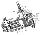
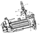
図1はステープル打ち用釘打機の斜視図で、同図において符号1は工具本体、2はグリップ、3はマガジンを示す。工具本体1の下部にはノーズ部4が設けられている。工具本体1にはグリップ2の後端から圧縮エアが供給され、圧縮エアはエアチャンバ5に貯留されている。
FIG. 1 is a perspective view of a stapling nailing machine. In FIG. 1,
上記釘打機は、トリガ6の引き上げ操作によりトリガバルブ7のバルブステム8を押し上げることにより作動させ、これにしたがってメインバルブ10のバルブ上室11に通じたエア管路12を大気に開放してバルブ上室11を減圧させ、メインバルブ10を図のように上方に開き作動させ、エアチャンバ5内の圧縮エアを打撃シリンダ13の上部に供給して打撃シリンダ13内に収容された打撃ピストン14とこれに一体的に結合したドライバ15とを下方に駆動し、マガジン3からノーズ部4に供給されたステープル(連結ステープル)sを打ち出すものである。
The nailing machine is operated by pushing up the
ステープルの打ち込み後、トリガ6を解放操作すると、トリガバルブ7が作動して、エアチャンバ5内の圧縮エアがエア管路12を経てバルブ上室11に供給される。これにより、メインバルブ10の上下端の差圧が逆転するので、メインバルブ10は下方に作動し、エアチャンバ5と打撃シリンダ13との管路が閉じ、打撃シリンダ13と排気チャンバとの管路が開かれる。この閉じ作動に伴って打撃シリンダ13内の圧縮エアが排気されるのである。
When the
なお、マガジン3にはステープルsの後端にプッシャ17が係合している。プッシャ17は常にプッシャバネ18により前方に付勢されてステープルsを押圧し、常時ノーズ部4の射出口内に送り出すように構成されている。なお、プッシャ17の上端部には突部20が形成されている。
Note that a
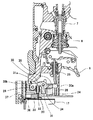
ところで、図2に示されるように、上記釘打機にはコンタクト部aが設けられている。コンタクト部aは射出口の先端が被打ち込み材に押し付けられたときに移動する部分で、ドライバガイド21とコンタクトアーム22とコンタクトボルト23と下部アーム24とから構成されている。
By the way, as shown in FIG. 2, the nailing machine is provided with a contact portion a. The contact portion a is a portion that moves when the tip of the injection port is pressed against the driven material, and includes a
ドライバガイド21はノーズ部4に沿って打ち込み方向に摺動可能に設けられ、ステープルsを打ち出すドライバ15と打ち出されたステープルsとをガイドする部材で、図示しないバネにより常時下方に付勢されている。コンタクトアーム22の一端22aはドライバガイド21に連結され、他端22bはドライバガイド21と平行に移動可能に設けられたコンタクトボルト23の中間部に螺合している。コンタクトボルト23の上端にはL字形の下部アーム24が係合されている。
The
ところで、下部アーム24の上部には上部アーム25が上下動可能に設けられている。上部アーム25の下部には係合溝26が形成され、上部アーム25の上端はトリガ6に回動自在に設けられたコンタクトレバー27の下面に係合可能に配置されている。コンタクトレバー27はトリガバルブ7のバルブステム8の下方に軸を中心に上下に回動可能に配置され、トリガ6が回動したときに、バルブステム8を押し込み可能に設けられている。
Incidentally, an
次に、上部アーム25と下部アーム24との間には空打ち防止機構bが設けられている。空打ち防止機構bは、図1に示されるように、空打ち防止アーム30とシーソーアーム31と空打ち防止ピン32とスライダ33と上記プッシャ17とから構成されている。
Next, an idle driving prevention mechanism b is provided between the
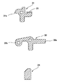
空打ち防止アーム30は、図2、図3及び図12に示されるように、上部アーム25と下部アーム24の間に横向きに配置され、その一端30aは上部アーム25の下部の係合溝26に係合可能に設けられ、他端30bは工具本体1に設けた支軸28に上下に回動可能に支持されている。
As shown in FIGS. 2, 3, and 12, the blanking
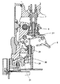
シーソーアーム31は、空打ち防止アーム30と重なるように配置され、その中間部は空打ち防止アーム30の中間部の回転軸34に揺動可能に設けられている。シーソーアーム31の一端は屈曲され、屈曲部35は下部アーム24の上端に係合可能に配置されている。また、シーソーアーム31の他端31aは工具本体1に設けられた空打ち防止ピン32の上端に係合可能に配置されている。
The
空打ち防止ピン32は圧縮バネ37により常に上方に付勢され、スライダ33の上部に支持されている。
The idling
スライダ33は横方向、つまりプッシャ17の移動方向と同じ方向にスライド可能に配置され、圧縮バネ36により常に空打ち防止ピン32を支持する方向に付勢されている。また、スライダ33は、プッシャ17の上端から突出した突部20と係合可能に配置され、最後のファスナーがなくなったときにプッシャ17が移動したときに上記突部20が係合し、さらにプッシャバネ18により上記圧縮バネ36に抗してスライドしたときには、空打ち防止ピン32の下端から外れるようになっている。
The
次に、上記釘打機を空打ち防止機構の作動態様とともに説明する。マガジン3内にステープルsが収納されているときは、プッシャ17の突部20はスライダ33に当たらないので、スライダ33は空打ち防止ピン32を支持している。この状態のとき、単打するために、図2及び図4のように、初めにドライバガイド21を被打込み材に押しつけると、ドライバガイド21自体は押し込まれて上動する。ドライバガイド21が上動すると、コンタクトアーム22とコンタクトボルト23と下部アーム24も上動する。
Next, the nailing machine will be described together with the operation mode of the idle driving prevention mechanism. When the staples s are stored in the
下部アーム24が上動すると、その上端はシーソーアーム31の一端35に当接して押し上げる。シーソーアーム31の一端35が押し上げられると、シーソーアーム31の他端31aは空打ち防止ピン32に支持されているから、ここを支点として全体が上方に移動する。シーソーアーム31が上動すると、その回転軸34も上動するから、空打ち防止アーム30も端部30bを中心に上方に回動する。空打ち防止アーム30の他端30aは上部アーム25の係合溝26に係合しているから、上部アーム25も上方に移動し、その上端はコンタクトレバー27に近接する。この状態でトリガ6を引き操作すると、図5に示されるように、コンタクトレバー27が持ち上げられ、トリガバルブ7のバルブステム8の下端に当接して押し上げる。これにより、トリガバルブ7が作動し、上述のようにメインバルブ10のバルブ上室11内の圧縮エアを排気させてメインバルブ10を開き作動させるから、ステープルsの打ちこみ作動が行なわれる。
When the
次に、ドライバガイド21を被打込み材から離すと、ドライバガイド21はバネによって下動し、コンタクトアーム22とコンタクトボルト23と下部アーム24も下動するので、シーソーアーム31も下方に移動し、空打ち防止アーム30も下方に回動するから、トリガ6を解放することにより、コンタクトレバー27はバルブステム8の下方に離れるので、トリガバルブ7は図3に示す初期状態に復帰し、メインバルブ10のバルブ上室11に圧縮エアを送るので、メインバルブ10が閉じ作動し、次のステープルs打ち込みが準備される。再びドライバガイド21を被打ち込み材に押し付けた後、トリガ6を引き上げ操作すると、次のステープル打ち込みが行われる。このようにして単打を行うことができる。
Next, when the
なお、トリガ6を引いたままドライバガイド21を被打込み材から離すと、図5に示すように、連単切り替えレバー38がトリガ爪部39に掛かり、上部アーム25の上端部位置が保持されるため、コンタクトレバー27は十分に高く押し上げられた状態が保持される。再度ステープルsの打ちこみ作動をするためには、まずトリガ6を解放しなければならない。このようにして単打が行なわれる。
If the
ところで、ステープルsを打ち込んだ後、トリガ6を解放し、ドライバガイド21を被打ち込み材に押し付けたまま横にずらして別の位置でステープル打ちを行う場合、トリガ6を解放することにより、打撃シリンダ13内の圧縮エアは排気され、メインバルブ10が閉じ作動するが、ドライバガイド21は図2と図4に示すように、被打ち込み材に押し付けられた状態になっているから、コンタクトレバー27は十分に高く押し上げられた状態が保持されている。したがって、ずらした位置で再びトリガ6を引き上げ操作すると、図5に示すようにトリガバルブ7が作動し、ステープルsの打ち込みが行われる。このようにしてズリ打ちをおこなうことができる。
By the way, when the staple s is driven, the
これに対し、ステープルsの打ちこみに当たり、初めにトリガ6を引き上げ操作すると、図6に示されるように、コンタクトレバー27が傾き、その先端は上部アーム25の上端に係合する。その後、ドライバガイド21の下端を被打込み材に押しつけてノーズ部4に対して上動させると、上述と同じ要領でコンタクトアーム22、コンタクトボルト23、下部アーム24が上動し、さらに図7のようにシーソーアーム31、空打ち防止アーム30が上部アーム25を上動させ、さらにコンタクトレバー27を上方に回動させるので、コンタクトレバー27がバルブステム8を押し上げ、これによりステープルsの打ちこみ作動が行なわれる。
On the other hand, when the
次に、トリガ6を引いたままドライバガイド21を被打込み材から離すと、図6と同じ状態になるから、再びドライバガイド21を被打込み材に押しつけると、上述と同様にして、図7のように下部アーム24が上動し、シーソーアーム31と空打ち防止アーム30が上方に回動して上部アーム25を上動させ、コンタクトレバー27を上方に回動させ、る。このとき、すでにトリガ6は引き上げ状態にあるので、コンタクトレバー27がバルブステム8を押し上げるので、トリガバルブ7、メインバルブ10が作動して次のステープルsの打ちこみ作動が行なわれる。
Next, when the
このようにして、トリガ6を引いた状態を維持したままドライバガイド21の先端を被打込み材に押しつける度にステープルsの打ちこむ連打を行なうことができる。
In this way, the staples s can be driven repeatedly each time the tip of the
上述のように、上記釘打機は連打単打が自動的に切り替えられるようになっている。 As described above, the nailing machine can automatically switch the single shot.
次に、マガジン3内にステープルが消費されるにつれてプッシャ17は前に進むので、最後のステープルsがなくなってプッシャ17がさらに前に進むと、上端の突部20がスライダ33を圧縮バネ36に抗して押し戻し方向にスライドさせ、図8に示されるように、空打ち防止ピン32の下から外す。スライダ33が空打ち防止ピン32から外れると、空打ち防止ピン32は支持を失って図9、図10のように落下するので、シーソーアーム31の他端31aの支持位置(支点)が低くなってしまう。この状態でドライバガイド21を被打込み材に押しつけ、下部アーム24を上動させても、図11に示されるように、シーソーアーム31は空回りするだけでほとんど上方に移動しないから、空打ち防止アーム30も同様にほとんど上方に回動しない。このため、上部アーム25もほんの僅かしか上動しないので、上部アーム25の上端はコンタクトレバー27を十分に押し上げることはできない。
Next, as the staple is consumed in the
したがって、トリガ6を引いた後にドライバガイド21を被打ち込み材に押し付ける連打操作をしても、ドライバガイド21を押し付けた後にトリガ6を引き上げ操作する単打操作をしても、結局は図11に示された状態となり、コンタクトレバー27はバルブステム8を押し上げることができないから、トリガバルブ7は作動しない。
Therefore, even if a continuous driving operation is performed in which the
また、単打を行うことができないから、ズリ打ちしようとしても、コンタクトレバー27が十分に回動していないので、ステープルsを打ちこむことはできない。
In addition, since a single stroke cannot be performed, the staple s cannot be driven because the
なお、コンタクト部aはドライバガイド21に限定されない。コンタクトアーム22が直接にノーズ部4の先端から突出してノーズ部4に摺動可能に設けられている構成でもよく、コンタクトボルト23を省略した構成でもよい。要するに、被打ち込み材にノーズ部4が押し付けられたことを検出するような部材であればよい。
The contact part a is not limited to the
なお、本発明はステープル用釘打機に限定されない。一般の釘打機、ネジ打ち機等の空気圧工具にも適用することができる。 The present invention is not limited to a staple nailing machine. The present invention can also be applied to pneumatic tools such as general nailing machines and screw driving machines.
3 マガジン
5 エアチャンバ
10 メインバルブ
13 打撃シリンダ
17 プッシャ
21 ドライバガイド
24 下部アーム
25 上部アーム
30 空打ち防止アーム
31 シーソーアーム
32 空打ち防止ピン
33 スライダ
3
Claims (2)
上記上部アームと下部アームの間に空打ち防止アームを横向きに配置し、空打ち防止アームの一端を上部アームに係合可能に設け、他端を工具本体に設けた支軸に上下に回動可能に支持させ、
空打ち防止アームの中間部の回転軸にはシーソーアームの中間部を揺動可能に設け、シーソーアームの一端を下部アームに係合可能に設け、
シーソーアームの他端を工具本体に設けられた空打ち防止ピンの上端に係合させるとともに、
空打ち防止ピンの下部を横方向にスライド可能でマガジンの最後のファスナーがなくなったときのファスナー押圧用プッシャと連動して横方向にスライド可能なスライダの上部に支持し、スライダがスライドしたときには空打ち防止ピンから外れるようにした
ことを特徴とする空気圧工具。 Provided with a nose part for punching fasteners at the lower part of the tool body equipped with a striking mechanism driven by air pressure, a magazine for pressing the fasteners with a pusher to the nose part, and a contact part slidable along the nose part, The lower end of the contact part protrudes from the tip of the nose part, a lower arm is provided at the upper end, and the upper arm can be engaged with a contact lever provided on the upper part of the lower arm so as to be rotatable. In the pneumatic tool provided to enable the triggering operation only when the upper arm sufficiently pushes up the contact lever and activates the striking mechanism,
A blanking prevention arm is arranged horizontally between the upper arm and the lower arm, and one end of the blanking prevention arm is provided to be engageable with the upper arm, and the other end is rotated up and down on a spindle provided on the tool body. Support as possible,
An intermediate part of the seesaw arm is swingably provided on the rotation shaft of the intermediate part of the idle arm, and one end of the seesaw arm is provided to be engageable with the lower arm.
While engaging the other end of the seesaw arm with the upper end of the anti-blank pin provided on the tool body,
The lower part of the anti-punch pin is slidable in the horizontal direction and is supported by the upper part of the slider that can be slid in the horizontal direction in conjunction with the pusher for pressing the fastener when the last fastener in the magazine is gone. A pneumatic tool characterized in that it is disengaged from the hit prevention pin.
Priority Applications (1)
| Application Number | Priority Date | Filing Date | Title |
|---|---|---|---|
| JP2008187148A JP5071286B2 (en) | 2008-07-18 | 2008-07-18 | Pneumatic tool |
Applications Claiming Priority (1)
| Application Number | Priority Date | Filing Date | Title |
|---|---|---|---|
| JP2008187148A JP5071286B2 (en) | 2008-07-18 | 2008-07-18 | Pneumatic tool |
Publications (2)
| Publication Number | Publication Date |
|---|---|
| JP2010023173A true JP2010023173A (en) | 2010-02-04 |
| JP5071286B2 JP5071286B2 (en) | 2012-11-14 |
Family
ID=41729492
Family Applications (1)
| Application Number | Title | Priority Date | Filing Date |
|---|---|---|---|
| JP2008187148A Active JP5071286B2 (en) | 2008-07-18 | 2008-07-18 | Pneumatic tool |
Country Status (1)
| Country | Link |
|---|---|
| JP (1) | JP5071286B2 (en) |
Cited By (1)
| Publication number | Priority date | Publication date | Assignee | Title |
|---|---|---|---|---|
| CN104802133A (en) * | 2015-05-14 | 2015-07-29 | 雷利锋 | Electric nail gun |
Citations (6)
| Publication number | Priority date | Publication date | Assignee | Title |
|---|---|---|---|---|
| JPS61257786A (en) * | 1985-05-09 | 1986-11-15 | 兼松日産農林株式会社 | Box nailing machine |
| JPH04210387A (en) * | 1990-11-30 | 1992-07-31 | Makita Corp | Preventing device for lost strike of nail in box nailing machine |
| JPH07246574A (en) * | 1994-03-11 | 1995-09-26 | Makita Corp | Nailing machine |
| JP2002346951A (en) * | 2001-05-25 | 2002-12-04 | Max Co Ltd | Blank shot preventing mechanism for tacker |
| JP2005118937A (en) * | 2003-10-16 | 2005-05-12 | Max Co Ltd | Unloaded shot preventing mechanism for nailing machine |
| JP2008068329A (en) * | 2006-09-12 | 2008-03-27 | Hitachi Koki Co Ltd | Fastener driver |
-
2008
- 2008-07-18 JP JP2008187148A patent/JP5071286B2/en active Active
Patent Citations (7)
| Publication number | Priority date | Publication date | Assignee | Title |
|---|---|---|---|---|
| JPS61257786A (en) * | 1985-05-09 | 1986-11-15 | 兼松日産農林株式会社 | Box nailing machine |
| JPH04210387A (en) * | 1990-11-30 | 1992-07-31 | Makita Corp | Preventing device for lost strike of nail in box nailing machine |
| JPH07246574A (en) * | 1994-03-11 | 1995-09-26 | Makita Corp | Nailing machine |
| JP2002346951A (en) * | 2001-05-25 | 2002-12-04 | Max Co Ltd | Blank shot preventing mechanism for tacker |
| JP2005118937A (en) * | 2003-10-16 | 2005-05-12 | Max Co Ltd | Unloaded shot preventing mechanism for nailing machine |
| US7600661B2 (en) * | 2003-10-16 | 2009-10-13 | Max Co., Ltd. | Nailing machine and magazine |
| JP2008068329A (en) * | 2006-09-12 | 2008-03-27 | Hitachi Koki Co Ltd | Fastener driver |
Cited By (1)
| Publication number | Priority date | Publication date | Assignee | Title |
|---|---|---|---|---|
| CN104802133A (en) * | 2015-05-14 | 2015-07-29 | 雷利锋 | Electric nail gun |
Also Published As
| Publication number | Publication date |
|---|---|
| JP5071286B2 (en) | 2012-11-14 |
Similar Documents
| Publication | Publication Date | Title |
|---|---|---|
| EP2666594B1 (en) | Fastening tool | |
| AU2009202885B2 (en) | Fastener driving device with mode selector and trigger interlock | |
| JP5034177B2 (en) | Driving tool safety device | |
| JP2727960B2 (en) | Nail driving device | |
| TWI389775B (en) | Nailing machine | |
| TWI727209B (en) | Punch tool | |
| EP1995023A1 (en) | Nailing device contact top attaching/detaching method | |
| JP4752751B2 (en) | Driving machine | |
| JP2005118937A (en) | Unloaded shot preventing mechanism for nailing machine | |
| JP4075462B2 (en) | Contact lever of trigger lever for starting nailer | |
| JP5071286B2 (en) | Pneumatic tool | |
| JP5055817B2 (en) | Contact mechanism in driving tools | |
| JP5286939B2 (en) | Driving machine | |
| JP2007075957A (en) | Single driving holding mechanism of nailing machine | |
| WO2007034850A1 (en) | Driving tool | |
| JP4461638B2 (en) | Immersion prevention mechanism in tucker | |
| JP4039369B2 (en) | Nailer starter | |
| JP2002346950A (en) | Blank shot preventing mechanism for nailer | |
| JP4052254B2 (en) | Nailer starter | |
| JPH0546854Y2 (en) | ||
| JP2556440Y2 (en) | Starter for continuous impact nailer | |
| JPH09141563A (en) | Bit slip-off preventing mechanism in drive screwdriver | |
| JP2519800Y2 (en) | Nail supply mechanism for continuous nailing machine | |
| JP4082356B2 (en) | Nailer starter | |
| JPH0727088Y2 (en) | Nail supply device for nailer |
Legal Events
| Date | Code | Title | Description |
|---|---|---|---|
| A621 | Written request for application examination |
Free format text: JAPANESE INTERMEDIATE CODE: A621 Effective date: 20100922 |
|
| TRDD | Decision of grant or rejection written | ||
| A01 | Written decision to grant a patent or to grant a registration (utility model) |
Free format text: JAPANESE INTERMEDIATE CODE: A01 Effective date: 20120724 |
|
| A01 | Written decision to grant a patent or to grant a registration (utility model) |
Free format text: JAPANESE INTERMEDIATE CODE: A01 |
|
| A61 | First payment of annual fees (during grant procedure) |
Free format text: JAPANESE INTERMEDIATE CODE: A61 Effective date: 20120806 |
|
| R150 | Certificate of patent or registration of utility model |
Ref document number: 5071286 Country of ref document: JP Free format text: JAPANESE INTERMEDIATE CODE: R150 Free format text: JAPANESE INTERMEDIATE CODE: R150 |
|
| FPAY | Renewal fee payment (event date is renewal date of database) |
Free format text: PAYMENT UNTIL: 20150831 Year of fee payment: 3 |