JP2010022073A - Information processor, and information processing method - Google Patents
Information processor, and information processing method Download PDFInfo
- Publication number
- JP2010022073A JP2010022073A JP2009248299A JP2009248299A JP2010022073A JP 2010022073 A JP2010022073 A JP 2010022073A JP 2009248299 A JP2009248299 A JP 2009248299A JP 2009248299 A JP2009248299 A JP 2009248299A JP 2010022073 A JP2010022073 A JP 2010022073A
- Authority
- JP
- Japan
- Prior art keywords
- epg
- receiver
- program guide
- electronic program
- information
- Prior art date
- Legal status (The legal status is an assumption and is not a legal conclusion. Google has not performed a legal analysis and makes no representation as to the accuracy of the status listed.)
- Granted
Links
Images


Abstract
Description
本発明は情報処理装置、および情報処理方法に関し、特に複数のシステムにおいて、統合した電子番組ガイドを得ることができるようにした情報処理装置、および情報処理方法に関する。 The present invention relates to an information processing apparatus and an information processing method, and more particularly, to an information processing apparatus and an information processing method capable of obtaining an integrated electronic program guide in a plurality of systems.
テレビジョン放送の番組を選択するための番組ガイドを画像信号に重畳して伝送し、受信側の表示装置において、これを表示するようにした、いわゆる電子番組ガイド(EPG:Electrical Program Guide)システムが知られている。 There is a so-called Electronic Program Guide (EPG) system in which a program guide for selecting a television broadcast program is transmitted by being superimposed on an image signal and displayed on a display device on the receiving side. Are known.
このEPGシステムには、例えば特表平6−504165号公報および関連する米国特許5,353,121公報に開示されているようなVBI(Vertical Blanking Interval)方式のものと、例えば特願平6−325940号として、本出願人が先に開示したデジタル直接衛星放送(DSS:Digital Satellite System(Hughes Communication社の商標)で用いられるようなデジタル衛星方式のものがある。 This EPG system includes, for example, a VBI (Vertical Blanking Interval) system disclosed in Japanese Patent Publication No. 6-504165 and related US Pat. No. 5,353,121, No. 325940 includes a digital satellite system such as that used in the digital direct satellite broadcasting (DSS: Digital Satellite System (trademark of Hughes Communication)) previously disclosed by the present applicant.
VBI方式は、通常(VHF(Very High Frequency)帯域)の地上波のテレビジョン放送において、その水平走査線の本来の画像に影響を与えない位置に、EPG(電子番組ガイド)を構成するVBIデータを挿入して、伝送するものである。受信側においては、このVBIデータを蓄積し、蓄積したVBIデータから、電子番組ガイドの表示データを生成し、モニタに表示するようにしている。 In the VBI system, in normal (VHF (Very High Frequency) band) terrestrial television broadcasting, VBI data that constitutes an EPG (electronic program guide) at a position that does not affect the original image of the horizontal scanning line. Is inserted and transmitted. On the receiving side, the VBI data is accumulated, display data of the electronic program guide is generated from the accumulated VBI data, and displayed on the monitor.
これに対して、デジタル衛星方式においては、EPGデータが、本来の画像データと共にデジタル化され、さらにパケット化されて伝送される。受信側においては、このEPGデータをメモリに蓄積し、対応する表示データを生成して、モニタに表示するようにする。 On the other hand, in the digital satellite system, the EPG data is digitized together with the original image data, and further packetized and transmitted. On the receiving side, the EPG data is stored in a memory, and corresponding display data is generated and displayed on the monitor.
いずれの方式においても、使用者は、モニタに表示された電子番組ガイドを見て、自分が視聴を希望する番組を選択することができる。 In either method, the user can select a program he / she wants to view by looking at the electronic program guide displayed on the monitor.
従来のAVシステムにおいては、例えば、地上波のテレビジョン放送を受信するシステムにおいては、このVBIのEPGを受信して、これを表示し、また、衛星放送を受信するシステムにおいては、衛星を介して伝送されるEPGを受信して、表示するようにしている。 In a conventional AV system, for example, in a system that receives a terrestrial television broadcast, the VBI EPG is received and displayed, and in a system that receives a satellite broadcast, the satellite is transmitted via a satellite. The received EPG is received and displayed.
このように、各システムにおいて、EPGが、それぞれ独立に機能しているため、例えば、所望の番組を地上波の放送でも、衛星を介した放送でもよいから視聴したい場合、その番組を放送しているか否か、放送しているのであれば、その日時などを、VBI方式のEPGで検索すると共に、もし、そのEPGに所望の番組がリストアップされていない(放送されていない)場合においては、同様の検索を衛星放送のEPGを利用して、再び行う必要がある。このため、所定の番組を迅速且つ確実に視聴することが困難となる課題があった。 As described above, since the EPG functions independently in each system, for example, if a desired program may be broadcast by terrestrial broadcasting or satellite broadcasting, the program is broadcast. If it is broadcasted, the date and time etc. are searched for in the VBI EPG, and if the desired program is not listed in the EPG (not broadcast), It is necessary to perform a similar search again using the EPG of satellite broadcasting. For this reason, there is a problem that it is difficult to view a predetermined program quickly and reliably.
本発明はこのような状況に鑑みてなされたものであり、所望の番組を、迅速且つ確実に、選択することができるようにするものである。 The present invention has been made in view of such circumstances, and enables a desired program to be selected quickly and reliably.
本発明の情報処理装置は、複数システムの電子番組ガイド情報それぞれが複数のチャンネルの番組の情報からなる、異なる複数のシステムの電子番組ガイド情報を受信する受信手段と、前記受信手段により受信された異なる複数システムの異なる複数の電子番組ガイド情報を、それぞれのフォーマットのまま記憶する記憶手段と、電子番組ガイドを表示する段階で前記記憶手段により記憶されている電子番組ガイドのフォーマットを統一し、重複するチャンネルの情報が削除された電子番組ガイドを表示するように制御する表示制御手段とを備える。 An information processing apparatus according to the present invention includes: a receiving unit configured to receive electronic program guide information of a plurality of different systems, wherein each of the electronic program guide information of a plurality of systems includes program information of a plurality of channels; The storage means for storing different electronic program guide information of different multiple systems in their respective formats, and the format of the electronic program guide stored in the storage means at the stage of displaying the electronic program guide are unified and duplicated Display control means for controlling to display the electronic program guide from which the channel information to be deleted is displayed.
視聴者の端末からの、特定の電子番組ガイド情報の提供の依頼に応じて、統合された前記電子番組ガイド情報を前記視聴者の端末に伝送する伝送手段をさらに備えるようにすることができる。 A transmission means for transmitting the integrated electronic program guide information to the viewer's terminal in response to a request for provision of specific electronic program guide information from the viewer's terminal can be further provided.
前記表示制御手段には、縦軸と横軸の一方と他方が時間軸とチャンネルで規定される電子番組ガイドとして単一のフォーマットに統合させることができる。 The display control means can be integrated into a single format as an electronic program guide in which one of the vertical axis and the horizontal axis is defined by the time axis and the channel.
前記表示制御手段には、前記電子番組ガイド情報を所定のチャンネルを指定して統合させることができる。 The display control means can integrate the electronic program guide information by designating a predetermined channel.
前記表示制御手段には、前記電子番組ガイド情報を番組の所定のカテゴリを指定して統合させることができる。 The display control means can integrate the electronic program guide information by designating a predetermined category of the program.
本発明の情報処理方法は、複数システムの電子番組ガイド情報それぞれが複数のチャンネルの番組の情報からなる、異なる複数のシステムの電子番組ガイド情報を受信する受信ステップと、前記受信ステップの処理により受信された異なる複数システムの異なる複数の電子番組ガイド情報を、それぞれのフォーマットのまま記憶する記憶ステップと、電子番組ガイドを表示する段階で前記記憶ステップの処理により記憶されている電子番組ガイドのフォーマットを統一し、重複するチャンネルの情報が削除された電子番組ガイドを表示するように制御する表示制御ステップとを含む。 The information processing method of the present invention includes a receiving step of receiving electronic program guide information of a plurality of different systems, each of which includes information of programs of a plurality of channels, and receiving by the processing of the receiving step. A storage step of storing a plurality of different electronic program guide information of different plurality of systems in their respective formats, and a format of the electronic program guide stored by the processing of the storage step at the stage of displaying the electronic program guide And a display control step for controlling to display an electronic program guide that is unified and from which information of overlapping channels is deleted.
本発明においては、複数システムの電子番組ガイド情報それぞれが複数のチャンネルの番組の情報からなる、異なる複数のシステムの電子番組ガイド情報が受信され、受信された異なる複数システムの異なる複数の電子番組ガイド情報が、それぞれのフォーマットのまま記憶される。また、電子番組ガイドを表示する段階で電子番組ガイドのフォーマットが統一され、重複するチャンネルの情報が削除された電子番組ガイドが表示される。 In the present invention, electronic program guide information of a plurality of different systems, each of which includes program information of a plurality of channels, each of which is received, and a plurality of different electronic program guides of the different systems received. Information is stored in each format. At the stage of displaying the electronic program guide, the format of the electronic program guide is unified, and the electronic program guide from which duplicate channel information is deleted is displayed.
本発明によれば、所望の番組を、迅速かつ確実に、選択させるようにすることができる。 According to the present invention, a desired program can be selected quickly and reliably.
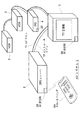
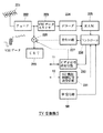
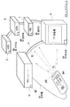
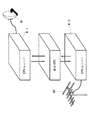
図1は、本発明の電子番組ガイドシステムを適用したAVシステムの構成例を表している。このAVシステム1においては、VCR(Video Cassete Recoder)2,3、IRD(Integrated Receiver/Decoder)4、テレビジョン(TV)受像機5およびEPGレシーバ6が、AVライン11とコントロールライン12により相互に接続されている。
FIG. 1 shows a configuration example of an AV system to which the electronic program guide system of the present invention is applied. In this
AVライン11は、コンポジットビデオ信号線、オーディオL信号線、オーディオR信号線の3本の線により構成されている。また、コントロールライン12は、後述するトランスレータ205(図2)を設けない場合においては、ワイヤードSIRCS(Wired Sony Infrared Remote Control System)の構成とすることができる。従って、これらのAV機器は、AVライン11を介して伝送されるビデオ信号とオーディオ信号を授受するビデオ信号送受信部と、コントロールライン12を介して授受されるコントロールデータを授受するAV機器制御信号送受信部とを有している。
The
また、EPGレシーバ6は、リモートコマンダ241が発生する赤外線信号(IR:Infrared)を受信するIR受信部6Bを有している。IRD4とTV受像機5は、リモートコマンダ5(図4)の発生する赤外線信号を受信するIR受信部4B,5Bを有している。
Further, the
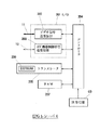
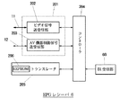
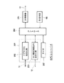
図2は、EPGレシーバ6の内部の構成例を表している。入出力(I/O)部201は、ビデオ信号送受信部202と、AV機器制御信号送受信部203とにより構成されている。ビデオ信号送受信部202は、AVライン11に対して、ビデオ信号とオーディオ信号を授受する動作を実行し、AV機器制御信号送受信部203は、コントロールライン12に対してコントロール信号を授受する処理を実行する。
FIG. 2 illustrates an internal configuration example of the
書き換え可能なメモリとしてのEEPROM(Electrically Erasable Programable Read Only Memory)206を内蔵するトランスレータ205は、AVシステム1を構成する各メーカのAV機器に対して送出するコマンドを、各メーカのAV機器において使用されるコマンドに変換する処理を行う。必要に応じて、比較的簡単に交換できるようになされているEEPROM206には、各メーカのAV機器において用いられるコマンドが記憶されている。バックアップされたRAM(Randum Access Memory)(あるいはEEPROMでもよい)207は、AVシステム1に接続されているAV機器が受信したEPGデータをデータベースとして記憶する。コントローラ204は、これらの各回路を適宜制御するようになされている。
A
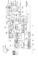
図3は、衛星放送を受信するためのIRD4の内部の構成例を示している。パラボラアンテナ61のLNB(Low Noise Block downconverter)61aより出力されたRF信号(ビットストリーム)は、フロントエンド20のチューナ21に供給され、復調される。チューナ21の出力は、QPSK復調回路22に供給され、QPSK復調される。QPSK復調回路22の出力は、エラー訂正回路23に供給され、エラーが検出、訂正され、必要に応じて補正される。
FIG. 3 shows an internal configuration example of the
CPU(Central Processor Unit)、ROM(Read Only Memory)およびRAM等からなるICカードにより構成されているCAM(Conditional Access Module)33には、暗号を解読するのに必要なキーが、解読プログラムとともに格納されている。衛星を介して送信される信号が暗号化されている場合、この暗号を解読するのにキーと解読処理が必要となる。そこで、カードリーダインタフェース32を介してCAM33からこのキーが読み出され、デマルチプレクサ(トランスポートIC)24に供給される。デマルチプレクサ24は、このキーを利用して、暗号化された信号を解読する。
The CAM (Conditional Access Module) 33, which is composed of an IC card consisting of a CPU (Central Processor Unit), ROM (Read Only Memory), RAM, etc., stores a key necessary for decrypting the cipher together with a decryption program. Has been. When a signal transmitted via a satellite is encrypted, a key and a decryption process are required to decrypt the encryption. Therefore, this key is read from the
尚、このCAM33には、暗号解読に必要なキーと解読プログラムの他、課金情報なども格納されている。
The
デマルチプレクサ24は、フロントエンド20のエラー訂正回路23の出力する信号の入力を受け、これをデータバッファメモリ(SRAM:Static Random Access Memory)35に一旦記憶させる。そして、適宜これを読み出し、解読したビデオ信号をMPEG(Moving Picture Experts Group)ビデオデコーダ25に供給し、解読したオーディオ信号をMPEGオーディオデコーダ26に供給する。
The
MPEGビデオデコーダ25は、入力されたデジタルビデオ信号をDRAM25aに適宜記憶させ、MPEG方式により圧縮されているビデオ信号のデコード処理を実行する。デコードされたビデオ信号は、NTSCエンコーダ27に供給され、NTSC方式の輝度信号(Y)、クロマ信号(C)、およびコンポジット信号(V)に変換される。輝度信号とクロマ信号は、バッファアンプ28Y,28Cを介して、それぞれSビデオ信号として出力される。また、コンポジット信号は、バッファアンプ28Vを介してAVライン11のビデオ信号線に出力される。
The
なお、このMPEGビデオデコーダ25としては、SGS−Thomson Microelectronics社のMPEG2復号化LSI(STi3500)を用いることができる。その概略は、例えば、日経PB社「日経エレクトロニクス」1994.3.14(no.603)第101頁乃至110頁に、Martin Bolton氏により紹介されている。
As the
また、MPEG2−Transportstreamに関しては、アスキー株式会社1994年8月1日発行の「最新MPEG教科書」第231頁乃至253頁に説明がなされている。
The MPEG2-Transportstream is described in
MPEGオーディオデコーダ26は、デマルチプレクサ24より供給されたデジタルオーディオ信号をDRAM26aに適宜記憶させ、MPEG方式により圧縮されているオーディオ信号のデコード処理を実行する。デコードされたオーディオ信号は、D/A変換器30においてD/A変換され、左チャンネルのオーディオ信号は、バッファアンプ31Lを介してAVライン11のオーディオL信号線に出力され、右チャンネルのオーディオ信号は、バッファアンプ31Rを介してAVライン11のオーディオ信号R信号線に出力される。
The
RFモジュレータ41は、NTSCエンコーダ27が出力するコンポジット信号と、D/A変換器30が出力するオーディオ信号とをRF信号に変換して出力する。また、このRFモジュレータ41は、TVモードが設定されたとき、ケーブルボックス等のAV機器から入力されるNTSC方式のRF信号をスルーして、VCRや他のAV機器にそのまま出力する。
The
この実施例の場合、これらのビデオ信号およびオーディオ信号が、AVライン11を介してVCR2,3、TV受像機5、EPGレシーバ6に供給されることになる。
In the case of this embodiment, these video signals and audio signals are supplied to the
CPU29は、ROM37に記憶されているプログラムに従って各種の処理を実行する。例えば、チューナ21、QPSK復調回路22、エラー訂正回路23などを制御する。また、AV機器制御信号送受信部39を制御し、コントロールライン12を介して、他のAV機器(この実施例の場合、VCR2,3、TV受像機5、EPGレシーバ6)に所定のコントロール信号を出力し、また、他のAV機器からのコントロール信号を受信する。
The
このCPU29に対しては、フロントパネル40の操作ボタンスイッチを操作して、所定の指令を直接入力することができる。また、リモートコマンダ5(図4)を操作すると、そのIR発信部51より赤外線信号が出射され、この赤外線信号がIR受信部4Bにより受光され、受光結果がCPU29に供給される。従って、リモートコマンダ5を操作することによっても、CPU29に所定の指令を入力することができる。
A predetermined command can be directly input to the
また、デマルチプレクサ24は、フロントエンド20から供給されるMPEGビデオデータとオーディオデータ以外に、EPGデータなどを取り込み、データバッファメモリ35のEPGエリア35Aに供給し、記憶させる。EPG情報は現在時刻から数十時間後までの各放送チャンネルの番組に関する情報(例えば、番組のチャンネル、トランスポンダ番号、放送時間、タイトル、カテゴリ、番組に出演している俳優名等)を含んでいる。このEPG情報は、頻繁に伝送されてくるため、EPGエリア35Aには常に最新のEPGを保持することができる。
In addition to the MPEG video data and audio data supplied from the
EEPROM38には、電源オフ後も保持しておきたいデータ(例えばチューナ21の4週間分の受信履歴、電源オフの直前に受信していたチャンネル番号(ラストチャンネル))などが適宜記憶される。そして、例えば、電源がオンされたとき、ラストチャンネルと同一のチャンネルを再び受信させる。ラストチャンネルが記憶されていない場合においては、ROM37にデフォルトとして記憶されているチャンネルが受信される。また、CPU29は、スリープモードが設定されている場合、電源オフ時であっても、フロントエンド20、デマルチプレクサ24、データバッファメモリ35など、最低限の回路を動作状態とし、受信信号に含まれる時刻情報から現在時刻を計時し、所定の時刻に各回路に所定の動作(いわゆるタイマ録音など)をさせる制御なども実行する。例えば、VCR2,3と連動して、タイマ自動録画を実行する。
The
さらに、CPU29は、所定のOSD(On−Screen Display)データを発生したいとき、MPEGビデオデコーダ25を制御する。MPEGビデオデコーダ25は、この制御に対応して所定のOSDデータを生成して、DRAM25aのOSDエリアに書き込み、さらに読み出して、出力する。これにより、所定の文字、図形などを含む電子番組ガイド、メニュー、その他を、適宜、TV受像機5に出力し、表示させることができる。
Further, the
CPU29はまた、モデム34を制御し、電話回線を介して他の装置と通信することができる。
The
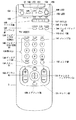
図4は、IRD4を遠隔制御するリモートコマンダ5のボタンスイッチ50の構成例を表している。セレクトボタンスイッチ131は、上下左右方向の4つの方向の他、その中間の4つの斜め方向の合計8個の方向に操作(方向操作)することができるばかりでなく、リモートコマンダ5の上面に対して垂直方向にも押下操作(セレクト操作)することができるようになされている。メニューボタンスイッチ134は、TV受像機5にメニュー画面を表示させるとき操作される。イグジットボタンスイッチ135は、元の通常の画面に戻る場合などに操作される。
FIG. 4 shows a configuration example of the button switch 50 of the
チャンネルアップダウンボタンスイッチ133は、受信する放送チャンネルの番号を、アップまたはダウンするとき操作される。ボリウムボタンスイッチ132は、ボリウムをアップまたはダウンさせるとき操作される。 The channel up / down button switch 133 is operated to increase or decrease the number of a broadcast channel to be received. The volume button switch 132 is operated when the volume is raised or lowered.
0乃至9の数字が表示されている数字ボタン(テンキー)スイッチ138は、表示されている数字を入力するとき操作される。エンタボタンスイッチ137は、数字ボタンスイッチ138の操作が完了したとき、数字入力終了の意味で、それに続いて操作される。チャンネルを切り換えたとき、新たなチャンネルの番号、コールサイン(名称)、ロゴ、メイルアイコンからなるバーナ(banner)が、3秒間表示される。このバーナには、上述したものからなる簡単な構成のものと、これらの他に、さらに、プログラム(番組)の名称、放送開始時刻、現在時刻なども含む、より詳細な構成のものの2種類があり、ディスプレイボタン136は、この表示されるバーナの種類を切り換えるとき操作される。
A numeric button (ten-key) switch 138 on which
テレビ/ビデオ切換ボタンスイッチ139は、TV受像機5の入力を、そこに内蔵されているチューナ222(図5)またはビデオ入力端子からの入力(VCR2,3などからの入力)に切り換えるとき操作される。テレビ/DSS切換ボタンスイッチ140は、地上波(VHF)を受信するテレビモードまたは衛星放送を受信するDSSモードを選択するとき操作される。数字ボタンスイッチ138を操作してチャンネルを切り換えると、切り換え前のチャンネルが記憶され、ジャンプボタンスイッチ141は、この切り換え前の元のチャンネルに戻るとき操作される。
The TV / video switching button switch 139 is operated when switching the input of the
ランゲージボタン142は、2カ国語以上の言語により放送が行われている場合において、所定の言語を選択するとき操作される。ガイドボタンスイッチ143は、メニューを介さずに、直接、電子番組ガイドをTV受像機5に表示させるとき操作される。
The
ケーブルボタンスイッチ145、テレビスイッチ146およびDSSボタンスイッチ147はファンクション切り換え用、すなわち、リモートコマンダ5から出射される赤外線信号のコードの機器カテゴリを切り換えるためのボタンスイッチである。ケーブルボタンスイッチ145は、ケーブルを介して伝送される信号をケーブルボックス(図示せず)で受信し、これをTV受像機5に表示させるとき操作され、これにより、ケーブルボックスに割り当てられた機器カテゴリのコードが赤外線信号として出射される。
The
同様に、テレビボタンスイッチ146は、TV受像機5に内蔵されているチューナにより受信した信号を表示させるとき操作される。DSSボタンスイッチ147は、衛星を介して受信した信号をIRD4で受信し、TV受像機5に表示させるとき操作される。LED148,149,150は、それぞれケーブルボタンスイッチ145、テレビボタンスイッチ146またはDSSボタンスイッチ147がオンされたとき点灯される。これにより、各種ボタンが押されたときに、どのカテゴリの機器に対して、コードが送信されたのかが示される。
Similarly, the TV button switch 146 is operated when displaying a signal received by a tuner built in the
ケーブル電源ボタンスイッチ151、テレビ電源ボタンスイッチ152、DSS電源ボタンスイッチ153がそれぞれ操作されたとき、ケーブルボックス、TV受像機5、またはIRD4の電源がオンまたはオフされる。
When the cable
ミューティングボタンスイッチ154は、TV受像機5のミューティング状態を設定または解除するとき操作される。スリープボタンスイッチ155は、所定の時刻になったとき、または所定の時間が経過したとき、自動的に電源をオフするスリープモードを設定または解除するとき操作される。
The
図5は、TV受像機5の内部の構成例を表している。チューナ222は、VHF用アンテナ221で受信した信号を復調し、復調信号を合成回路を228を介してCRT229に出力し、表示させる。また、VBIデータスライサ223は、チューナ222の出力からVBIデータを抽出し、その抽出結果をデコーダ224に出力する。デコーダ224は、VBIデータスライサ223の出力するVBIデータをデコードし、EPGデータを生成して、バックアップされたRAM(またはEEPROM)225に記憶させる。
FIG. 5 shows an internal configuration example of the
コントローラ226は、RAM225に記憶されているEPGデータを元に、発生回路227を制御し、OSDデータ(表示データ)を発生させ、合成回路228を介して、CRT229に出力し、表示させる。
The
ビデオ信号送受信部230は、AVライン11に対して、ビデオ信号とオーディオ信号を授受する処理を実行し、AV機器制御信号送受信部231は、コントロールライン12に対してコントロール信号を授受する処理を実行する。IR受信部5Bは、リモートコマンダ5からの赤外線信号を受信し、受信検知信号をコントローラ226に出力する。
The video signal transmission /
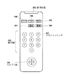
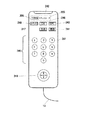
図6は、EPGレシーバ6を遠隔制御するリモートコマンダ241の構成例を表している。EPGボタンスイッチ243は、TV受像機5に統合された電子番組ガイドを表示させるとき操作される。機器ボタンスイッチ244は、統合したい電子番組ガイドを指定するとき操作される。例えば、この実施例においては、IRD4とTV受像機5が、EPGを受信する機能を有しているが、このうちの任意の機器、例えばTV受像機5の電子番組ガイドを表示させたいとき、この機器ボタンスイッチ244が操作され、それに続いて、このAVシステム1において、TV受像機5に割り当てられた番号に対応する数字を、数字ボタンスイッチ245を操作することで入力する。
FIG. 6 shows a configuration example of the
また、チャンネル(CH)、番組、または番組のカテゴリを指定したいとき、チャンネルボタンスイッチ246、番組ボタンスイッチ247、またはカテゴリボタンスイッチ248に続き、数字ボタンスイッチ245が操作される。セレクトボタンスイッチ249は、図4のリモートコマンダ5のセレクトボタンスイッチ131と同様に、方向操作とセレクト操作が行われる。
When it is desired to designate a channel (CH), a program, or a category of a program, the
いずれかのボタンスイッチが操作されたとき、その操作されたボタンスイッチに対応する赤外線信号がIR発信部242より出射され、EPGレシーバ6のIR受信部6Bにより受信されるようになされている。
When any one of the button switches is operated, an infrared signal corresponding to the operated button switch is emitted from the
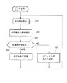
EPGレシーバ6のコントローラ204は、その電源がオンされている状態において、図7のフローチャートに示すEPGデータ記憶処理を実行する。最初にステップS21において、コントローラ204は、AVシステム1に接続されているAV機器の中から、EPGデータを受信する受信機器を選択する。例えば、最初にIRD4を選択する。次に、ステップS22に進み、コントローラ204は、ステップS21で選択した受信機器に対して、EPGデータの受信を要求する。いまの場合、コントローラ204は、AV機器制御信号送受信部203およびコントロールライン12を介して、IRD4にEPGデータの受信を要求する。
The
IRD4は、AV機器制御信号送受信部39を介して、このコマンドを受け取る。EPGレシーバ6とIRD4の製造メーカは、必ずしも同一であるとは限らない。通常、メーカが異なると、各AV機器は制御するコマンドも異なるものとなる。そこで、コントローラ204は、IRD4に対してEPGデータの受信を要求するコマンドを発生したとき、このコマンドをトランスレータ205に供給し、IRD4のメーカにおいて用いられているコマンドに変換させる。トランスレータ205は、各メーカに対応するコマンドに変換できるように、各メーカのシステムにおいて用いられるコマンドを、EEPROM206に記憶している。トランスレータ205は、このEEPROM206の記憶データに従って、コマンドをIRD4のメーカのコマンドに変換する。
The
なお、AVシステム1に、各AV機器を接続したとき、コントローラ204は、コントロールライン12を介して、各AV機器に対して、メーカ名を問い合わせ、そのメーカ名をRAM207に記憶している。そこで、このRAM207に記憶されているメーカのシステムで用いられているコマンドを、トランスレータ205に発生させる。
When each AV device is connected to the
従って、IRD4のCPU29は、AV機器制御信号送受信部39を介して、このコマンドを適正なコマンドとして受け取ることができる。そして、このコマンドを受け取ったとき、CPU29は、デマルチプレクサ24を制御し、データバッファメモリ35のEPGエリア35Aに記憶されているEPGデータを読み出させる。上述したように、EPGエリア35Aには、常に最新のEPGデータが更新され、記憶されている。
Therefore, the
CPU29は、このEPGデータを読み出すと、AV機器制御信号送受信部39、コントロールライン12を介して、EPGレシーバ6に出力する。
When reading the EPG data, the
EPGレシーバ6のコントローラ204は、AV機器制御信号送受信部203を介して、このEPGデータを受け取ることになる。
The
そして、ステップS23において、使用者がリモートコマンダ241を操作してEPGデータを記憶する条件を指定しているか否かを判定する。記憶すべき条件が特に指定されていない場合においては、ステップS25に進み、予めデフォルトとして規定されている条件で、EPGデータをRAM207に記憶させる。この場合、基本的に、全てのチャンネルの番組の、その番組を選択する上において必要な最低限の情報(例えば放送チャンネル、トランスポンダ名、番組名、放送時刻)を記憶させる。
In step S23, it is determined whether or not the user operates the
一方、ステップS23において記憶すべき条件が指定されていると判定された場合、ステップS24に進み、その指定された条件で、EPGデータがRAM207に記憶される。
On the other hand, when it is determined in step S23 that the condition to be stored is designated, the process proceeds to step S24, and the EPG data is stored in the
例えば、使用者がリモートコマンダ241を操作して、統合すべきEPG(RAM207に記憶すべきEPG)として、所定のチャンネルを指定することができる。このチャンネルの指定は、リモートコマンダ241のチャンネルボタンスイッチ246と、数字ボタンスイッチ245を操作することで行われる。また、所定のカテゴリに属する番組のEPGデータだけを、RAM207に記憶させたい場合においては、そのカテゴリを、カテゴリボタンスイッチ248と数字ボタンスイッチ245を操作することで指定する。さらに、所定の番組のEPGデータをRAM207に記憶させたい場合においては、番組ボタンスイッチ247と数字ボタンスイッチ245を操作して、その番組を特定する番号が入力される。
For example, the user can operate the
このような、記憶すべき条件が入力されている場合においては、コントローラ204は、指定された条件に従ったEPGデータをRAM207に記憶させる。
When such a condition to be stored is input, the
次に、ステップS21に戻り、他の受信機器が選択される。例えば、TV受像機5が受信機器として選択される。そして、ステップS22において、コントローラ204は、TV受像機5に対して、EPGデータの受信を要求する。この要求コマンドも、RAM207に予め記憶されているTV受像機5のメーカに対応するコマンドにトランスレータ205で変換される。そして、この変換されたコマンドが、コントロールライン12を介して、TV受像機5のAV機器制御信号送受信部231に入力される。
Next, returning to step S21, another receiving device is selected. For example, the
TV受像機5のコントローラ226は、AV機器制御信号送受信部231より、このコマンドの入力を受けたとき、RAM225に記憶されているEPGデータを読み出す。RAM225にEPGデータが記憶されていない場合においては、チューナ222を制御し、EPGデータを受信させ、RAM225に記憶させる。そして、記憶されたEPGデータを読み出し、AV機器制御信号送受信部231、コントロールライン12を介して、EPGレシーバ6に出力する。
When the
EPGレシーバ6のコントローラ204は、このEPGデータをAV機器制御信号送受信部203を介して受信したとき、上述した場合と同様に、ステップS23において、記憶条件が指定されていると判定された場合においては、ステップS24に進み、指定された条件でRAM207に、そのEPGデータを記憶させる。また、特に記憶する条件が指定されていない場合においてはステップS25に進み、デフォルトとして規定されている条件でEPGデータをRAM207に記憶させる。
When the
以上のようにして、RAM207にAVシステム1に接続されている、各AV機器に対して、EPGデータの受信が要求され、その要求に従って受信された(あるいは、予め記憶されている)EPGデータが、RAM207にまとめて記憶される。
As described above, each AV device connected to the
なお、この図7のフローチャートに示す処理においては、IRD4とTV受像機5において受信されたEPGデータは、基本的に、それぞれのフォーマットのままで、RAM207に記憶される。従って、例えば実質的に同一の番組がIRD4とTV受像機5において、異なる時刻、あるいは同一の時刻において放送される場合であっても、それぞれのEPGデータが、基本的に全てRAM207に記憶される。その結果、後述する図8のフローチャートに示す処理のように、データを統一されたフォーマットに統合して記憶する場合に較べて、RAM207の容量が多く必要となる。ただし、このようにしたとしても、後述する図10のフローチャートに示すように、表示の段階でフォーマットを統一することで、操作性を改善することができる
In the process shown in the flowchart of FIG. 7, the EPG data received by the
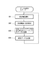
図8は、EPGデータを記憶する、他の処理例を表している。この実施例においては、ステップS31において、EPGレシーバ6のコントローラ204により、EPGデータを受信する受信機器が選択される。上述したように、例えばIRD4が選択指定される。次にステップS32に進み、コントローラ204は、ステップS31で選択指定されたIRD4に対して、EPGデータの受信を要求する。IRD4は、この要求を受けたとき、この要求に従ってEPGデータを読み出し、EPGレシーバ6に出力する。以上の処理は、図7のステップS21,S22における処理と同様の処理である。
FIG. 8 shows another example of processing for storing EPG data. In this embodiment, in step S31, the
次に、ステップS33に進み、コントローラ204は、受信したIRD4のEPGデータを所定のフォーマット(統合フォーマット)のデータに変換する。そして、ステップS34に進み、ステップS33で変換したデータをRAM207に記憶する。
In step S33, the
さらにステップS31に戻り、次のAV機器、例えばTV受像機5を選択する。そして、ステップS32においてTV受像機5に対してEPGデータの受信を要求する。TV受像機5は、この要求に従ってEPGデータを受信し、これをEPGレシーバ6に出力する。
Further, returning to step S31, the next AV device, for example, the
EPGレシーバ6のコントローラ204は、ステップS33において、受信したEPGデータを統合フォーマットのデータに変換する。そしてステップS34に進み、変換したデータをRAM207に記憶する。
In step S33, the
以上のようにして、AVシステム1に接続されているAV機器のEPGデータが統合フォーマットの状態で、RAM207に記憶される。
As described above, the EPG data of the AV device connected to the
すなわち、図7と図8に示すいずれの記憶処理の場合も、AVシステム1に接続されているAV機器が受信するEPGデータをデータベース化して、RAM207に記憶させるのであるが、図8に示す実施例の場合、統合フォーマットに変換した状態で各AV機器のEPGデータが記憶される。従って、例えばIRD4とTV受像機5において、実質的に同一の内容の番組(同一の番組名を有する番組)が、同一の時刻、あるいは異なる時刻において、放送されるものとして、EPGデータに登録されている場合、共通の情報は1つだけ記憶し、放送時間帯、放送地域などの異なる情報だけを付加的に記憶するようにする。これにより、RAM207の容量を少なくすることが可能となる。
That is, in any of the storage processes shown in FIGS. 7 and 8, the EPG data received by the AV device connected to the
同一の番組であるか否かは、その番組の番組名(タイトル)の先頭の、例えば10文字が一致するか否かから判定することができる。あるいは、VBI方式やデジタル衛星方式のEPGシステムで各番組に統一した固有のIDが付加されているときは、IDを比較することで判定することができる。 Whether or not they are the same program can be determined from whether or not, for example, 10 characters at the head of the program name (title) of the program match. Alternatively, when a unique ID is added to each program in the VBI or digital satellite EPG system, it can be determined by comparing the IDs.
あるいは、放送チャンネル名が一致しているか否かから判定することもできる。この場合、スポーツ中継等、同じ放送チャンネル名であっても、各地域(サービスエリア)毎に異なる番組(例えば、異なる野球試合の中継)が放送される可能性があるため、放送チャンネル名の一致判定の後、番組名の一致を判定し、異なる番組が存在する場合は、情報として保存しておく処理が必要となる。 Alternatively, it can be determined from whether or not the broadcast channel names match. In this case, even if the broadcast channel name is the same for sports broadcasts, etc., there is a possibility that different programs (for example, relays of different baseball games) may be broadcast for each region (service area). After the determination, it is determined whether the program names match, and if there is a different program, a process for storing it as information is required.
さらにまた、このように、フォーマットを統一化することで、所定の番組を検索することが容易となる。すなわち、このAVシステム1で受信可能な番組のEPGデータは1つの統一されたデータベースとされるので、このデータベースで1回検索行うだけで、このAVシステム1で受信可能な番組であるか否かを迅速に知ることができる。
Furthermore, by unifying the format in this way, it becomes easy to search for a predetermined program. That is, since the EPG data of a program that can be received by this
また、使用者が一度見た番組のEPGデータは、使用者の要求があれば抹消するようにすれば、RAM207の記憶領域を、より効率的に利用することが可能となる。このとき、番組名は、消去せずに残しておき、使用者が一度見た番組として、その履歴をRAM207に記憶させるようにすることもできる。このようにすれば、一度見た番組を検索することも可能になる。
Further, if the EPG data of the program once viewed by the user is deleted if requested by the user, the storage area of the
以上のようにして、EPGレシーバ6のRAM207には、常に最新のEPGデータが統合して、データベース化されて記憶される。
As described above, the latest EPG data is always integrated and stored in the
このようにEPGレシーバ6のRAM207には、異なるシステムの電子番組ガイドがデータベース化されて記憶されるのであるが、各システムの電子番組ガイドは基本的に異なっている。
As described above, the electronic program guides of different systems are stored in the
例えば、衛星放送を介して伝送される番組を受信するには、チャンネルだけでなくトランスポンダの番号も必要となる。これに対して、地上波を介して伝送される番組を選択するには、チャンネル番号だけが必要となり、トランスポンダの番号は不要である。従って、IRD4で受信するEPGデータにはトランスポンダの番号が含まれているが、TV受像機5で受信するEPGデータには、トランスポンダ番号は含まれていない。
For example, in order to receive a program transmitted via satellite broadcasting, not only a channel but also a transponder number is required. On the other hand, in order to select a program transmitted via the terrestrial wave, only the channel number is required, and the transponder number is not necessary. Therefore, the EPG data received by the
また、TV受像機5で受信する番組のEPGデータには、その番組をVCR2,3などで予約録画する場合に必要なコードが含まれているが、衛星放送の電子番組ガイドには、これらのコードが含まれていない。
Further, the EPG data of the program received by the
このような違いは、統合後のEPGデータにおいてもそのまま保持される。 Such a difference is maintained as it is in the integrated EPG data.
次に、図9のフローチャートを参照して、所望の番組を選択する場合の処理について説明する。この処理は、リモートコマンダ241のEPGボタンスイッチ243を操作したとき、その処理が開始される。
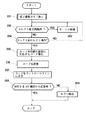
Next, processing when a desired program is selected will be described with reference to the flowchart of FIG. This process is started when the
最初にステップS51において、電子番組ガイドを表示する処理が実行される。この表示処理は、RAM207に対する記憶処理が、図7のフローチャートに示すように行われている場合においては、図10のフローチャートに示すように行われ、記憶処理が図8のフローチャートに示すように行われている場合においては、図11のフローチャートに示すように行われる。
First, in step S51, processing for displaying an electronic program guide is executed. This display process is performed as shown in the flowchart of FIG. 10 when the storage process in the
すなわち、RAM207への記憶処理が、図7のフローチャートに示すように、基本的にEPGデータを統一フォーマットに統合しない状態で行われる場合においては、図10に示すように、最初にステップS71において、RAM207に記憶されているEPGデータが読み出され、この読み出されたデータが、ステップS72において統合フォーマットのデータに変換される。そして、ステップS73において、統合フォーマットデータに変換されたEPGデータを表示する処理が実行される。
That is, when the storage processing in the
具体的には、コントローラ204は、RAM207に記憶されているIRD4のEPGデータと、TV受像機5のEPGデータとを、表示上統合されたフォーマットのデータに変換し、そのデータをAV機器制御信号送受信部203とコントロールライン12を介してTV受像機5に出力する。
Specifically, the
TV受像機5のコントローラ226は、このEPGデータをAV機器制御信号送受信部231を介して受信したとき、発生回路227を制御し、このEPGデータに対応する表示データ(OSDデータ)を発生させる。このOSDデータは、合成回路228を介してCRT229に出力され表示される。
When the
これにより、RAM207上においては統合されていないが、少なくとも表示状態においては、異なるAV機器(システム)のEPGデータが統合されたフォーマットでTV受像機5のCRT229に表示される。従って、使用者は、異なるAV機器における番組選択を同様の操作感覚で選択することが可能となる。
Thereby, although not integrated on the
なお、この電子番組ガイド表示時に、表示するEPGデータの条件をさらに設定できるようにしてもよい。 It should be noted that when displaying the electronic program guide, the conditions of the EPG data to be displayed may be further set.
一方、RAM207への記憶処理が、図8のフローチャートに示すように行われた場合、RAM207には、既に統合されたフォーマットの状態で、EPGデータが記憶されている。この場合の、図9のステップS51のEPGデータの表示処理は、図11に示すように行われる。
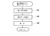
On the other hand, when the storage process in the
すなわち、最初にステップS81において、使用者は、RAM207に記憶されているEPGデータのうち、表示するEPGデータを指定する。この指定は、図7のステップS23における記録条件指定処理に対応する。すなわち、図7の実施例においては、予め条件を設定し、その条件に対応するEPGデータをRAM207に記憶させるようにしたのであるが、この実施例においては、基本的に全てのデータをRAM207に記憶させ、その中から所定の条件を指定し、その条件を満足するEPGデータを読み出すようにしている。これにより例えば、所定のカテゴリのEPGデータを指定したり、所定の番組番号を有す得る番組のEPGデータを表示させるようにすることができる。あるいはまた、EPGデータに、各番組に出演している俳優も登録されている場合においては、その俳優を指定して、その俳優が出演している番組のEPGデータを読み出すようにすることもできる。
That is, first in step S81, the user designates EPG data to be displayed among the EPG data stored in the
ステップS81でこのような指定が行われると、ステップS82において指定されたデータがRAM207から読み出され、ステップS83において、その読み出されたデータを表示する処理が実行される。
When such a designation is made in step S81, the data designated in step S82 is read from the
すなわち、コントローラ204は、指定された条件に対応するEPGデータをRAM207に記憶されているデータベースから検索し、その検索の結果得られたデータを読み出し、TV受像機5用のODSデータ発生コマンドを付加して出力する。
That is, the
TV受像機5のコントローラ226は、上述した場合と同様にして、この入力されたデータに対応するOSDデータを発生回路227に発生させ、CRT229に表示させる。
The
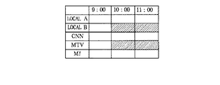
図12は、このようにして、CRT229に表示された電子番組ガイドの表示例を表している。図13(IRD4で受信した電子番組ガイド)、図14(TV受像機5で受信した電子番組ガイド)、および、図12の電子番組ガイドを比較して明らかなように、図12に示す表示例においては、図13と図14に示す電子番組ガイドが統合された状態で表示されている。
FIG. 12 shows a display example of the electronic program guide displayed on the
なお、RAM207の容量が不足する場合においては、例えば図15に示すように、EPGデータのうち1部を削除して表示するようにすることができる。
When the capacity of the
以上のようにして、図9のステップS51の電子番組ガイドの表示処理が行われると、次にステップS52に進み、リモートコマンダ241のセレクトボタンスイッチ249の方向操作が行われたか否かが判定される。方向操作が行われたと判定された場合、ステップS53に進み、操作された方向にカーソルを移動する処理が実行される。
When the electronic program guide display process in step S51 of FIG. 9 is performed as described above, the process proceeds to step S52, where it is determined whether or not the direction operation of the
すなわち、リモートコマンダ241のセレクトボタンスイッチ249を上下左右に方向操作する。すると、この方向操作に対応する赤外線信号が、IR発信部242より出射され、EPGレシーバ6のIR受信部6Bで受信される。EPGレシーバ6のコントローラ204は、IR受信部6Bを介して方向操作信号を受信したとき、トランスレータ205に、TV受像機5用のカーソル移動コマンドを発生させる。このコマンドはコントロールライン12を介してTV受像機5に伝送される。
That is, the
TV受像機5のコントローラ226は、このコマンドの入力を受けたとき、発生回路227を制御し、CRT229の電子番組ガイドに表示されているカーソル(図12)を操作方向に対応して移動させる。この電子番組ガイドには、横軸に時刻が、縦軸にチャンネルが表示され、各チャンネルの放送時刻の位置に、その番組名が表示されている。カーソルをその番組名上に移動させることで、番組を選択する。
When receiving the command, the
次に、ステップS54に進み、セレクトボタンスイッチ249がセレクト操作(押圧操作)されたか否かが判定される。セレクト操作されていなければ、ステップS52に戻り、方向操作に対応する処理に戻る。使用者は、カーソルを所定の番組上に移動させた後、その番組の選択を確定するとき、セレクトボタンスイッチ249を押圧し、セレクト操作を行う。ステップS54において、このセレクト操作が行われたと判定された場合、ステップS55に進み、コントローラ204は、そのときカーソルの位置する番組を選択するコマンドコードを発生する処理を実行する。
In step S54, it is determined whether or not the
すなわち、TV受像機5のコントローラ226は、コントロールライン12を介してセレクト操作を検知したとき、AV機器制御信号送受信部231を制御し、そのときカーソルが位置する位置情報を、コントロールライン12を介して、EPGレシーバ6に出力する。
That is, when the
EPGレシーバ6のコントローラ204は、AV機器制御信号送受信部203を介して、この位置情報の入力を受けたとき、その位置に対応する番組を判定する。コントローラ204は、TV受像機5に表示されている電子番組ガイドを自ら発生しているので、その位置情報から、そこに表示されている番組を知ることができる。
When the
そして、コントローラ204は、その番組を受信するAV機器に対して、その受信を要求するコマンドを発生する。例えば、選択されたのが、IRD4により受信される番組(すなわち、衛星を介して放送される番組)である場合においては、IRD4に対して、その受信を要求するコマンドを発生し、TV受像機5により受信される番組(すなわち、地上波により放送される番組)である場合においては、TV受像機5に対して、その受信を要求するコマンドを発生する。
Then, the
次に、ステップS56に進み、コントローラ204は、発生したコマンドをトランスレータ205に送り、送出先のAV機器(いまの場合、IRD4またはTV受像機5)のメーカに対応するコマンドコードに変換させる。そして、そのAV機器のメーカに対応するコマンドコードが、ステップS57において、コントロールライン12を介して、そのAV機器(IRD4またはTV受像機5)に送出される。
In step S56, the
このコマンド変換処理は、ステップS56において特に代表的に示されているが、上述の説明で明らかなように、EPGデータ記憶処理、カーソル移動処理などにおいても適宜行われている。 This command conversion processing is particularly representatively shown in step S56, but as is apparent from the above description, it is also appropriately performed in EPG data storage processing, cursor movement processing, and the like.
IRD4は、AV機器制御信号送受信部39を介して、この受信要求信号の入力を受けたとき、フロントエンド20を制御し、指定された番組の受信を指令する。その結果、指令に対応する番組が受信され、その映像信号がAVライン11を介して、TV受像機5に伝送される。
When receiving the reception request signal via the AV device control signal transmission /
TV受像機5は、ビデオ信号送受信部230を介して、この映像信号の入力を受けたとき、これを合成回路228を介して、CRT229に出力し、表示させる。
When receiving the video signal input via the video signal transmission /
一方、TV受像機5のコントローラ226は、受信要求信号をAV機器制御信号送受信部231を介して受信したとき、チューナ222を制御し、指定された番組の受信を指令する。その結果、チューナ222により受信された映像信号が、合成回路228を介して、CRT229に出力され、表示される。
On the other hand, when receiving the reception request signal via the AV device control signal transmission /
受信要求のコマンドの入力を受けたAV機器(IRD4またはTV受像機5)は、指定されたチャンネルの番組を受信したとき、受信が完了したことを表すステータス信号を、コントロールライン12を介して、EPGレシーバ6に出力する。
The AV device (
EPGレシーバ6のコントローラ204は、ステップS58で、このステータス信号の入力を受け、指定された番組の受信処理が完了したことを検知したとき、処理を終了する。何らかの理由で、指定した番組の受信が完了できなかった場合においては、このステータス信号の入力を受けることができない。そこで、この場合においては、ステップS59に進み、エラー処理を実行する。例えば、コントローラ204は、エラーメッセージを発生し、コントロールライン12を介して、TV受像機5に出力し、それを表示させる。
In step S58, the
以上の実施例においては、EPGレシーバ6に専用のリモートコマンダ241を介して各種の指令を入力するようにしたが、例えば図16に示すように、EPGレシーバ6にLCDパネル261と透明のタッチパネル262を設け、LCDパネル261に各種の表示を行わせ、タッチパネル262を指などで操作させ、各種の入力を行うことができるようにすることもできる。この場合においては、LCDパネル261に統合された電子番組ガイドを表示させ、タッチパネル262を操作することで、所定の番組を選択させることができる。
In the above embodiment, various commands are input to the
なお、以上の実施例においては、所定の番組を選択する動作について説明したが、選択した番組をVCR2,3などに予約録画させるようにすることも勿論可能である。
In the above embodiment, the operation of selecting a predetermined program has been described. However, it is of course possible to make the selected program be reserved and recorded in the
上記実施例においては、EPGレシーバ6を遠隔制御する専用のリモートコマンダ241を設けるようにしたが、他のAV機器、例えばIRD4(およびTV受像機5)を遠隔制御するリモートコマンダ5を用いて、EPGレシーバ6を制御するようにすることも可能である。この場合、リモートコマンダ5の各種のボタンスイッチを操作すると、その操作に対応する赤外線信号が、IR発信部51から発生される。
In the above embodiment, the dedicated
IRD4のCPU29は、IR受信部4Bを介して、このIR信号による制御信号の入力を受けると、その制御信号に対応するコマンドをリモートコントロールライン12を介して、EPGレシーバ6に出力する。EPGレシーバ6のコントローラ204は、このコマンドをAV機器制御信号送受信部203を介して受け取ると、対応する処理を実行する。
When the
この場合、EPGレシーバ6を、図2に示すように構成すれば、そのRAM207に、上述した場合と同様にして、統合したEPGデータを記憶させることができる。
In this case, if the
なお、リモートコマンダ5の出射する赤外線信号をEPGレシーバ6のIR受信部6Bで直接受信して、各種の動作を実行させるようにすることもできる。
The infrared signal emitted from the
上記実施例においては、IRD4の受信する番組のEPGデータと、TV受像機5の受信する番組のIRDデータとを、それぞれ両者とは異なる第3の統合フォーマットに統合するようにしたが、TV受像機5の番組のEPGフォーマットを、IRD4の番組のEPGフォーマットに変換することで統合したり、あるいは逆に、IRD4のEPGデータをTV受像機5のEPGフォーマットに変換して統合するようにすることもできる。
In the above embodiment, the EPG data of the program received by the
例えば、EPGレシーバ6をIRD4のリモートコマンダ5により制御するようにする場合においては、TV受像機5のEPGデータを、IRD4のEPGデータのフォーマットに変換して統合するようにすることができる。そして、この統合したEPGデータを、EPGレシーバ6のRAM207に記憶するようにすることもできるが、IRD4のEPGエリア35Aに記憶させるようにすることもできる。この場合においては、図17に示すように、EPGレシーバ6には、RAM207が不要となる。
For example, when the
このように、TV受像機5のEPGデータを、IRD4のEPGデータのフォーマットに変換して統合した場合における電子番組ガイドの表示例を、図18に示す。この表示例においても、図12に示す表示例における場合と同様に、異なる受信システムの電子番組ガイドを共通の電子番組ガイドとして利用することができる。そして、この実施例の場合、新たな第3のフォーマットとされるわけではないので、常にIRD4の電子番組ガイドを操作する感覚で、番組選択などの操作を行うことが可能となる。
FIG. 18 shows a display example of the electronic program guide when the EPG data of the
上記実施例においては、リモートコマンダ241によりEPGレシーバ6だけを遠隔制御するようにしたが、例えば、図19に示すように、EPGレシーバ6を制御線13でリモートコマンダ241と接続し、EPGレシーバ6の発生する赤外線信号で他のAV機器を直接制御するようにすることもできる。この場合、TV受像機5のIR受信部5B、IRD4のIR受信部4Bなどと同様に、VCR2,3にIR受信部2B,3Bを設ける。そして、EPGレシーバ6から他のAV機器にコマンドを出力するとき、制御線13を介してリモートコマンダ241を制御し、赤外線信号により各AV機器にコマンドを出力させるようにする。
In the above embodiment, only the
この場合、EPGレシーバ6には、例えば図20に示すように、IR制御部271を設ける。そして、トランスレータ205は、他のAV機器にコマンドを送出するとき、必要となるものであるため、EPGレシーバ6には設けずに、図21に示すように、リモートコマンダ241に内蔵させるようにする。
In this case, the
コントローラ204は、他のAV機器にコマンドを出力するとき、IR制御部271を制御し、制御線13を介してリモートコマンダ241に信号を送る。リモートコマンダ241は、コマンドの入力を受けたとき、トランスレータ205で各AV機器に対応するコマンドに変換して、赤外線信号を発生する。
When the
ただし、IRD2やTV受像機5より、EPGデータの伝送を受ける必要があるため、EPGレシーバ6を少なくともコントロールライン12で他のAV機器と接続しておく必要がある。
However, since it is necessary to receive transmission of EPG data from the
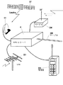
なお、図22に模式的に示すように、TV受像機5の受信するEPGデータを地上波を受信するアンテナ221で受信したり、IRD4が受信する衛星301を介して伝送される電波をアンテナ61で受信することで受信する他、例えば、ページャ304、ケーブル306、無線電話機305などを介して、その他のEPGデータを受信し、これを統合するようにすることも可能である。
As schematically shown in FIG. 22, the EPG data received by the
また、図23に示すように、EPGレシーバが複数台(EPGレシーバ6−1とEPGレシーバ6−2)存在する場合、さらに、これを結合して、1つの統合されたEPG(結合EPG)を生成し、これをEPGレシーバ6−1または6−2の一方に記憶させるか、他の装置に記憶させるようにすることができる。 Further, as shown in FIG. 23, when there are a plurality of EPG receivers (EPG receiver 6-1 and EPG receiver 6-2), these are combined to form one integrated EPG (combined EPG). Can be generated and stored in one of the EPG receivers 6-1 or 6-2, or stored in another device.
また、図24に示すように、複数のEPGレシーバが存在するとき、より優れた表示機能を有する(より優れたOSD機能を有する)EPGレシーバを用いて、具体的な表示を行わせるようにすることもできる。 Also, as shown in FIG. 24, when there are a plurality of EPG receivers, a specific display is performed using an EPG receiver having a better display function (having a better OSD function). You can also
例えば、図24の実施例においては、アンテナ221で地上波を受信し、そのEPGデータを受信するEPGレシーバ6−2より、アンテナ61を介して衛星から放送されてくる電波を受信して、そのEPGデータを受信するレシーバ6−1の方が、より高度の表示機能を有している。この場合、EPGレシーバ6−2とEPGレシーバ6−1で受信されたEPGデータに基づいて統合されたデータベース351を生成するが、受像機5にこのデータベース351に統合されたEPGデータに対応する表示を行わせるとき、その制御は、EPGレシーバ6−2ではなく、EPGレシーバ6−1を用いて行うようにする。これにより、表示機能の劣るEPGレシーバ6−2のEPGデータも、より高度の表示機能を実質的に有するものとなる。
For example, in the embodiment of FIG. 24, a radio wave broadcast from a satellite is received via an
以上の実施例においては、各家庭において異なるシステムのEPGデータを統合するようにしたが、図25に示すように、所定の中継基地局321において、アンテナ322乃至324、ケーブル325などを介して、各種の独立したEPGデータを受信し、これを統合するようにすることができる。そして、中継基地局321は、例えば、電話線330を介して、各家庭から特定の統合されたEPGデータの提供の依頼を受け、依頼を受けた統合されたEPGデータを、アンテナ326,327,328、あるいはケーブル329を介して、各家庭に伝送するようにすることができる。
In the above embodiment, EPG data of different systems is integrated in each home, but as shown in FIG. 25, in a predetermined
この場合、中継基地局321が、そのサービスエリア(地域)内のEPGデータだけを抽出することができるようにするため、郵便番号(ZIPコード)などのポスタルコード(郵便物を配送する地域を特定するための郵便物配布地域情報)をEPGデータに含めて伝送するようにすることができる。受信側では、サービスエリア内のポスタルコードを指定し、サービスエリア内のポスタルコードを有するEPGデータのみを抽出する。そして、抽出したEPGデータだけを統合する。
In this case, in order to enable the
また、例えば、米国においては、衛星を介して伝送されてくるEPGデータの番組の放送時刻には、夏時間補正(Daylight Savings Time Correction)の為のオフセット情報が含まれている。さらに米国においては、PST(Pacific Standard Time)、MSD(Mountain Standard Time)、CST(Central Standard Time)、EST(East Standard Time)の4つの標準時があるので、各地域で用いられるEPGの放送時刻は4つの標準時の内の視聴者の地域に応じた何れかの標準時で表示しなければならず、その為にタイムゾーン補正を施す必要がある。そして各標準時は、グリニッジ標準時からのオフセット値で表されている。中継基地局321は、そのサービスエリアに応じて、このオフセット値の補正を行い、さらに、衛星を介して伝送されてくるオフセット情報に基づいて夏時間補正を行い、これにより統合したEPGデータとすることができる。
For example, in the United States, the broadcast time of a program of EPG data transmitted via a satellite includes offset information for daylight savings time correction. Furthermore, in the United States, there are four standard times: PST (Pacific Standard Time), MSD (Mountain Standard Time), CST (Central Standard Time), and EST (East Standard Time). It must be displayed in any one of the four standard times according to the viewer's area, and it is necessary to correct the time zone for that purpose. Each standard time is represented by an offset value from Greenwich Mean Time. The
なお、EPGレシーバ6に、AVシステム1のすべてのEPGデータを受信する専用の受信回路を内蔵させることもできる。
The
1 AVシステム, 2,3 VCR, 4 IRD, 5 テレビジョン受像機, 6 EPGレシーバ, 11 AVライン, 12 コントロールライン, 202 ビデオ信号送受信部, 203 AV機器制御信号送受信部, 205 トランスレータ, 206 EEPROM, 207 RAM 1 AV system, 2, 3 VCR, 4 IRD, 5 Television receiver, 6 EPG receiver, 11 AV line, 12 Control line, 202 Video signal transmission / reception unit, 203 AV equipment control signal transmission / reception unit, 205 Translator, 206 EEPROM, 207 RAM
Claims (6)
前記受信手段により受信された異なる複数システムの異なる複数の電子番組ガイド情報を、それぞれのフォーマットのまま記憶する記憶手段と、
電子番組ガイドを表示する段階で前記記憶手段により記憶されている電子番組ガイドのフォーマットを統一し、重複するチャンネルの情報が削除された電子番組ガイドを表示するように制御する表示制御手段と
を備える情報処理装置。 Receiving means for receiving electronic program guide information of a plurality of different systems, each of the electronic program guide information of a plurality of systems comprising information of programs of a plurality of channels;
Storage means for storing a plurality of different electronic program guide information of different systems received by the receiving means in their respective formats;
Display control means for controlling so as to display the electronic program guide from which the information of the overlapping channel is deleted by unifying the format of the electronic program guide stored in the storage means at the stage of displaying the electronic program guide. Information processing device.
ことを特徴とする請求項1に記載の情報処理装置。 The transmission apparatus according to claim 1, further comprising a transmission unit configured to transmit the integrated electronic program guide information to the viewer terminal in response to a request for provision of specific electronic program guide information from the viewer terminal. The information processing apparatus according to 1.
ことを特徴とする請求項1に記載の情報処理装置。 2. The information processing apparatus according to claim 1, wherein the display control unit is integrated into a single format as an electronic program guide in which one of the vertical axis and the horizontal axis is defined by a time axis and a channel.
ことを特徴とする請求項1に記載の情報処理装置。 The information processing apparatus according to claim 1, wherein the display control unit integrates the electronic program guide information by designating a predetermined channel.
ことを特徴とする請求項1に記載の情報処理装置。 The information processing apparatus according to claim 1, wherein the display control unit integrates the electronic program guide information by designating a predetermined category of a program.
前記受信ステップの処理により受信された異なる複数システムの異なる複数の電子番組ガイド情報を、それぞれのフォーマットのまま記憶する記憶ステップと、
電子番組ガイドを表示する段階で前記記憶ステップの処理により記憶されている電子番組ガイドのフォーマットを統一し、重複するチャンネルの情報が削除された電子番組ガイドを表示するように制御する表示制御ステップと
を含む情報処理方法。 A receiving step of receiving electronic program guide information of a plurality of different systems, each of the electronic program guide information of a plurality of systems comprising information of programs of a plurality of channels;
Storing a plurality of different electronic program guide information of different systems received by the process of the receiving step in their respective formats;
A display control step for controlling to display the electronic program guide from which the information of the overlapping channel is deleted by unifying the format of the electronic program guide stored by the processing of the storing step at the stage of displaying the electronic program guide; Information processing method including:
Priority Applications (1)
| Application Number | Priority Date | Filing Date | Title |
|---|---|---|---|
| JP2009248299A JP4666099B2 (en) | 2009-10-28 | 2009-10-28 | Information processing apparatus and information processing method |
Applications Claiming Priority (1)
| Application Number | Priority Date | Filing Date | Title |
|---|---|---|---|
| JP2009248299A JP4666099B2 (en) | 2009-10-28 | 2009-10-28 | Information processing apparatus and information processing method |
Related Parent Applications (1)
| Application Number | Title | Priority Date | Filing Date |
|---|---|---|---|
| JP2007011664A Division JP4554624B2 (en) | 2007-01-22 | 2007-01-22 | Information processing apparatus and information processing method |
Publications (2)
| Publication Number | Publication Date |
|---|---|
| JP2010022073A true JP2010022073A (en) | 2010-01-28 |
| JP4666099B2 JP4666099B2 (en) | 2011-04-06 |
Family
ID=41706429
Family Applications (1)
| Application Number | Title | Priority Date | Filing Date |
|---|---|---|---|
| JP2009248299A Expired - Lifetime JP4666099B2 (en) | 2009-10-28 | 2009-10-28 | Information processing apparatus and information processing method |
Country Status (1)
| Country | Link |
|---|---|
| JP (1) | JP4666099B2 (en) |
Cited By (1)
| Publication number | Priority date | Publication date | Assignee | Title |
|---|---|---|---|---|
| WO2011096332A1 (en) | 2010-02-03 | 2011-08-11 | 日本電気株式会社 | Base station, mobile communication system and system information transmitting method |
Citations (9)
| Publication number | Priority date | Publication date | Assignee | Title |
|---|---|---|---|---|
| JPS61129984A (en) * | 1984-11-29 | 1986-06-17 | Sony Corp | Receiver for tv broadcasting |
| JPS61133785A (en) * | 1984-12-03 | 1986-06-21 | Sony Corp | Receiver of television broadcast |
| JPS63244982A (en) * | 1987-03-30 | 1988-10-12 | Nec Corp | Individual selective calling receiver incorporated television receiver |
| JPH0583688A (en) * | 1991-09-19 | 1993-04-02 | Toshiba Corp | Teletext receiver |
| JPH05122674A (en) * | 1991-10-28 | 1993-05-18 | Pioneer Electron Corp | Catv system |
| JPH06319140A (en) * | 1993-08-06 | 1994-11-15 | C Harvey John | Signal processing method |
| JPH08502155A (en) * | 1992-08-07 | 1996-03-05 | エヌビイエル・コミュニケーションズ・インコーポレーテッド | Video distribution network |
| JPH08275077A (en) * | 1995-03-31 | 1996-10-18 | Sony Corp | Electronic program guide system and electronic program guide display method |
| JPH08317979A (en) * | 1994-02-28 | 1996-12-03 | Carmeli Adahan | Pump suitable for artificial respiratory apparatus and its exhaust valve assembly |
-
2009
- 2009-10-28 JP JP2009248299A patent/JP4666099B2/en not_active Expired - Lifetime
Patent Citations (9)
| Publication number | Priority date | Publication date | Assignee | Title |
|---|---|---|---|---|
| JPS61129984A (en) * | 1984-11-29 | 1986-06-17 | Sony Corp | Receiver for tv broadcasting |
| JPS61133785A (en) * | 1984-12-03 | 1986-06-21 | Sony Corp | Receiver of television broadcast |
| JPS63244982A (en) * | 1987-03-30 | 1988-10-12 | Nec Corp | Individual selective calling receiver incorporated television receiver |
| JPH0583688A (en) * | 1991-09-19 | 1993-04-02 | Toshiba Corp | Teletext receiver |
| JPH05122674A (en) * | 1991-10-28 | 1993-05-18 | Pioneer Electron Corp | Catv system |
| JPH08502155A (en) * | 1992-08-07 | 1996-03-05 | エヌビイエル・コミュニケーションズ・インコーポレーテッド | Video distribution network |
| JPH06319140A (en) * | 1993-08-06 | 1994-11-15 | C Harvey John | Signal processing method |
| JPH08317979A (en) * | 1994-02-28 | 1996-12-03 | Carmeli Adahan | Pump suitable for artificial respiratory apparatus and its exhaust valve assembly |
| JPH08275077A (en) * | 1995-03-31 | 1996-10-18 | Sony Corp | Electronic program guide system and electronic program guide display method |
Cited By (1)
| Publication number | Priority date | Publication date | Assignee | Title |
|---|---|---|---|---|
| WO2011096332A1 (en) | 2010-02-03 | 2011-08-11 | 日本電気株式会社 | Base station, mobile communication system and system information transmitting method |
Also Published As
| Publication number | Publication date |
|---|---|
| JP4666099B2 (en) | 2011-04-06 |
Similar Documents
| Publication | Publication Date | Title |
|---|---|---|
| JP3372004B2 (en) | Electronic program guide device, electronic program guide system, and electronic program guide method | |
| US7224323B2 (en) | Bi-directional communication system, display apparatus, base apparatus and bi-directional communication method | |
| US5886691A (en) | Display control method for display having buttons representing selectable voting items in which only marks assigned to selected items continue to be displayed upon selection | |
| US6084643A (en) | Receiving equipment and method of using the same | |
| JP3685277B2 (en) | Image display control apparatus and method | |
| JP3931344B2 (en) | Electronic program guide information processing method | |
| JP3539453B2 (en) | Electronic program guide display control apparatus and method | |
| JP3646887B2 (en) | Electronic program guide transmission apparatus and method, and electronic program guide reception apparatus and method | |
| JP4666099B2 (en) | Information processing apparatus and information processing method | |
| JP3240051B2 (en) | Electronic program guide data processing method | |
| JP3862148B2 (en) | Electronic program guide data processing method | |
| JP4554624B2 (en) | Information processing apparatus and information processing method | |
| JP4341644B2 (en) | Display control apparatus and method | |
| JP3562051B2 (en) | Electronic program guide display control apparatus and method | |
| JP4229061B2 (en) | Image display control apparatus and method | |
| US20050175320A1 (en) | Broadcast program recording system, broadcast program recording method and broadcast program recording control method | |
| JP3611001B2 (en) | Receiving method and receiving apparatus | |
| JP3646296B2 (en) | Image display control apparatus and method | |
| JP3662295B2 (en) | Electronic program guide transmission apparatus and method, and electronic program guide reception apparatus and method | |
| JP2000295585A (en) | System and display method for electronic program guide | |
| JP3539452B2 (en) | Electronic program guide display control apparatus and method | |
| JP3603288B2 (en) | Operation control apparatus and method | |
| JP4364073B2 (en) | Electronic program guide transmission apparatus and method | |
| JP3922582B2 (en) | Display control apparatus and method | |
| JP4688169B2 (en) | Receiving apparatus and receiving method |
Legal Events
| Date | Code | Title | Description |
|---|---|---|---|
| A621 | Written request for application examination |
Free format text: JAPANESE INTERMEDIATE CODE: A621 Effective date: 20091030 |
|
| A131 | Notification of reasons for refusal |
Free format text: JAPANESE INTERMEDIATE CODE: A131 Effective date: 20100406 |
|
| A521 | Written amendment |
Free format text: JAPANESE INTERMEDIATE CODE: A523 Effective date: 20100607 |
|
| A131 | Notification of reasons for refusal |
Free format text: JAPANESE INTERMEDIATE CODE: A131 Effective date: 20100930 |
|
| A521 | Written amendment |
Free format text: JAPANESE INTERMEDIATE CODE: A523 Effective date: 20101119 |
|
| TRDD | Decision of grant or rejection written | ||
| A01 | Written decision to grant a patent or to grant a registration (utility model) |
Free format text: JAPANESE INTERMEDIATE CODE: A01 Effective date: 20101214 |
|
| A01 | Written decision to grant a patent or to grant a registration (utility model) |
Free format text: JAPANESE INTERMEDIATE CODE: A01 |
|
| A61 | First payment of annual fees (during grant procedure) |
Free format text: JAPANESE INTERMEDIATE CODE: A61 Effective date: 20101227 |
|
| FPAY | Renewal fee payment (event date is renewal date of database) |
Free format text: PAYMENT UNTIL: 20140121 Year of fee payment: 3 |
|
| FPAY | Renewal fee payment (event date is renewal date of database) |
Free format text: PAYMENT UNTIL: 20140121 Year of fee payment: 3 |
|
| R250 | Receipt of annual fees |
Free format text: JAPANESE INTERMEDIATE CODE: R250 |
|
| R250 | Receipt of annual fees |
Free format text: JAPANESE INTERMEDIATE CODE: R250 |
|
| EXPY | Cancellation because of completion of term |