JP2010021096A - Temperature distribution measuring device, fuel cell system, and fuel cell evaluation device - Google Patents
Temperature distribution measuring device, fuel cell system, and fuel cell evaluation device Download PDFInfo
- Publication number
- JP2010021096A JP2010021096A JP2008182409A JP2008182409A JP2010021096A JP 2010021096 A JP2010021096 A JP 2010021096A JP 2008182409 A JP2008182409 A JP 2008182409A JP 2008182409 A JP2008182409 A JP 2008182409A JP 2010021096 A JP2010021096 A JP 2010021096A
- Authority
- JP
- Japan
- Prior art keywords
- temperature distribution
- fuel cell
- distribution measuring
- measuring device
- substrate
- Prior art date
- Legal status (The legal status is an assumption and is not a legal conclusion. Google has not performed a legal analysis and makes no representation as to the accuracy of the status listed.)
- Granted
Links
Images


Classifications
-
- Y—GENERAL TAGGING OF NEW TECHNOLOGICAL DEVELOPMENTS; GENERAL TAGGING OF CROSS-SECTIONAL TECHNOLOGIES SPANNING OVER SEVERAL SECTIONS OF THE IPC; TECHNICAL SUBJECTS COVERED BY FORMER USPC CROSS-REFERENCE ART COLLECTIONS [XRACs] AND DIGESTS
- Y02—TECHNOLOGIES OR APPLICATIONS FOR MITIGATION OR ADAPTATION AGAINST CLIMATE CHANGE
- Y02E—REDUCTION OF GREENHOUSE GAS [GHG] EMISSIONS, RELATED TO ENERGY GENERATION, TRANSMISSION OR DISTRIBUTION
- Y02E60/00—Enabling technologies; Technologies with a potential or indirect contribution to GHG emissions mitigation
- Y02E60/30—Hydrogen technology
- Y02E60/50—Fuel cells
Abstract
Description
本発明は、燃料電池のセル間に挟持され、当該セル面内の温度分布を測定するための温度分布測定装置に関し、特に、薄型・軽量であって、かつ、燃料電池の内部抵抗を高めることを防いで発電に悪影響を及ぼすことなく、セル面内の温度分布を測定可能な温度分布測定装置、および当該温度分布測定装置を用いる燃料電池システム、ならびに当該温度分布測定装置を用いて燃料電池の性能評価を行う燃料電池評価装置に関するものである。 The present invention relates to a temperature distribution measuring device that is sandwiched between cells of a fuel cell and measures the temperature distribution in the cell surface, and in particular, is thin and lightweight, and increases the internal resistance of the fuel cell. The temperature distribution measuring device capable of measuring the temperature distribution in the cell surface without adversely affecting the power generation, the fuel cell system using the temperature distribution measuring device, and the fuel cell using the temperature distribution measuring device The present invention relates to a fuel cell evaluation apparatus that performs performance evaluation.
従来、燃料電池内部の温度測定は、特許文献1に開示されているように抵抗体を用いて、あるいは、特許文献2に開示されているようにシース熱電対を用いて行われていた。簡単に説明すると、まず特許文献1では、燃料電池のセル間に挟まれている電流測定装置100内に電流測定用抵抗体121が複数設けられた第2基板120が備えられており、この電流測定用抵抗体121を用いてセルの電流(電流分布)を測定している(特許文献1の図3参照)。そして、電流測定用抵抗体121の温度特性を補正するために、電流測定装置100内に温度測定用抵抗体141が複数設けられた第4基板140が備えられており、この温度測定用抵抗体141を用いてセルの温度(温度分布)を測定していることが開示されている(特許文献1の図6参照)。次に、引用文献2では、測温側先端に絶縁膜をコーティングしたシース熱電対を用いてセルの温度を測定することが開示されている(特許文献2の図5参照)。
特許文献1における抵抗体を用いる方法では、電流測定のために抵抗体を用いるため、燃料電池の内部抵抗が高くなり、発電に悪影響を与えるという問題を生じる。また、電流測定用抵抗体の温度特性を補正するために抵抗体による温度測定を行うため、定電流印加回路と温度測定用抵抗体の電圧測定回路とが必要になり、回路が複雑になるという問題を生じる。
In the method using the resistor in
また、特許文献2におけるシース熱電対を用いる方法では、当該シース熱電対を挟み込むために、当該シース熱電対を挟む電極間の密着性に悪影響を与えるという問題を生じる。また、発電時、燃料電池のセル間には2〜3(A/cm2)程度の電流密度で電流が流れており、上記シース熱電対を用いて直接測定を行えば、発電された電流による計測器の破損、および発電への悪影響が懸念される。すなわち、上記シース熱電対をそのまま実際に用いることは困難であるという問題を生じる。
Moreover, in the method using the sheath thermocouple in
本発明は、上記の問題点を鑑みてなされたものであり、その目的は、薄型・軽量であって、かつ、燃料電池の内部抵抗を高めることを防いで発電に悪影響を及ぼすことなく、セル面内の温度分布を測定可能な温度分布測定装置、および当該温度分布測定装置を用いる燃料電池システム、ならびに当該温度分布測定装置を用いて燃料電池の性能評価を行う燃料電池評価装置を提供することにある。 The present invention has been made in view of the above-mentioned problems, and its object is to achieve a cell that is thin and lightweight and prevents an increase in internal resistance of the fuel cell without adversely affecting power generation. To provide a temperature distribution measuring device capable of measuring an in-plane temperature distribution, a fuel cell system using the temperature distribution measuring device, and a fuel cell evaluation device for evaluating the performance of the fuel cell using the temperature distribution measuring device. It is in.
本発明に係る温度分布測定装置は、上記課題を解決するために、燃料電池の積層されたセル間に配置され、当該セル面内の温度分布を測定するための温度分布測定装置であって、複数の絶縁体を積層してなる基板と、上記基板の両面に上記セルに接触するように設けられ、かつ互いが電気的に接続されている一対の電極と、上記基板における内層に形成され、かつ、上記セルおよび上記電極とは電気的に接続されていない、熱電対を構成する複数の金属パターンとを備えていることを特徴としている。 In order to solve the above problems, a temperature distribution measuring apparatus according to the present invention is a temperature distribution measuring apparatus that is disposed between stacked cells of a fuel cell and measures the temperature distribution in the cell plane, A substrate formed by laminating a plurality of insulators, a pair of electrodes provided on both surfaces of the substrate so as to be in contact with the cell, and electrically connected to each other; and an inner layer of the substrate; And the said cell and the said electrode are provided with the some metal pattern which comprises the thermocouple which is not electrically connected.
また、本発明に係る燃料電池システムは、上記課題を解決するために、上記および下記の温度分布測定装置が積層されたセル間に配置されている燃料電池と、上記温度分布測定装置における熱電対から電圧を測定する電圧測定部と、上記電圧測定部にて測定された電圧に基づき、上記熱電対の熱起電力特性と室温とから温度を算出するとともに、当該算出した温度に基づき温度分布を生成する演算部とを備えていることを特徴としている。 In order to solve the above problems, a fuel cell system according to the present invention includes a fuel cell arranged between cells in which the above and below described temperature distribution measuring devices are stacked, and a thermocouple in the temperature distribution measuring device. Based on the voltage measured by the voltage measuring unit and the voltage measured by the voltage measuring unit, the temperature is calculated from the thermoelectromotive force characteristics of the thermocouple and the room temperature, and the temperature distribution is calculated based on the calculated temperature. It is characterized by comprising a calculation unit for generation.
また、本発明に係る燃料電池評価装置は、上記課題を解決するために、燃料電池の性能評価を行う燃料電池評価装置であって、燃料電池の積層されたセル間に配置されている、上記および下記の温度分布測定装置における熱電対から電圧を測定する電圧測定部と、上記電圧測定部にて測定された電圧に基づき、上記熱電対の熱起電力特性と室温とから温度を算出するとともに、当該算出した温度に基づき温度分布を生成し、この生成した温度分布を用いて上記燃料電池の性能評価を行う評価部とを備えていることを特徴としている。 The fuel cell evaluation apparatus according to the present invention is a fuel cell evaluation apparatus that performs performance evaluation of a fuel cell in order to solve the above-described problems, and is disposed between stacked cells of the fuel cell. And calculating the temperature from the thermoelectromotive force characteristics of the thermocouple and the room temperature based on the voltage measurement unit for measuring the voltage from the thermocouple in the temperature distribution measuring device described below and the voltage measured by the voltage measurement unit. And an evaluation unit that generates a temperature distribution based on the calculated temperature and evaluates the performance of the fuel cell using the generated temperature distribution.
上記の構成によれば、本発明に係る温度分布測定装置は、燃料電池のセル間に配置されるものであって、基板に、熱電対を構成する複数の金属パターンが、上記セル、および上記基板と上記セルとの電気的接続のための電極と電気的に接続されないようにして形成されている。このように、上記温度分布測定装置は、基板に熱電対を構成する金属パターンを設けて温度測定を行うために薄型・軽量が可能であり、それゆえ上記温度分布測定装置がセル間に配置されていても燃料電池の薄型・軽量を実現できる。また、以上の構成により、燃料電池の内部抵抗を高めることがなく、燃料電池の発電に悪影響を及ぼすことがない。 According to the above configuration, the temperature distribution measuring device according to the present invention is disposed between cells of a fuel cell, and a plurality of metal patterns constituting a thermocouple are formed on the substrate, the cell, and the above It is formed so as not to be electrically connected to an electrode for electrical connection between the substrate and the cell. As described above, the temperature distribution measuring apparatus can be thin and lightweight because the metal pattern constituting the thermocouple is provided on the substrate to perform temperature measurement. Therefore, the temperature distribution measuring apparatus is disposed between the cells. Even so, the fuel cell can be made thinner and lighter. Further, the above configuration does not increase the internal resistance of the fuel cell and does not adversely affect the power generation of the fuel cell.
以上のことから、薄型・軽量であって、かつ、燃料電池の内部抵抗を高めることを防いで発電に悪影響を及ぼすことなく、セル面内の温度分布を測定可能な温度分布測定装置、および当該温度分布測定装置を用いる燃料電池システム、ならびに当該温度分布測定装置を用いて燃料電池の性能評価を行う燃料電池評価装置を提供することができるという効果を奏する。 From the above, a temperature distribution measuring device that is thin and lightweight and that can measure the temperature distribution in the cell plane without adversely affecting power generation by preventing the increase in internal resistance of the fuel cell, and There is an effect that it is possible to provide a fuel cell system that uses a temperature distribution measuring device and a fuel cell evaluation device that performs performance evaluation of the fuel cell using the temperature distribution measuring device.
本発明に係る温度分布測定装置は、上記基板の上記電極を形成した面の面積は、上記セル面の面積と比較して大きく形成されており、かつ、上記基板の両面における上記セル面より大きい部分には、上記熱電対を構成する金属パターンと電気的に接続されている、上記熱電対の電極となる金属パターンが設けられていることが好ましい。 In the temperature distribution measuring apparatus according to the present invention, the area of the surface of the substrate on which the electrodes are formed is formed larger than the area of the cell surface, and is larger than the cell surface on both surfaces of the substrate. The portion is preferably provided with a metal pattern serving as an electrode of the thermocouple, which is electrically connected to the metal pattern constituting the thermocouple.
本発明に係る温度分布測定装置は、上記電極として、隣接するセルのセパレータを用いることが好ましい。 The temperature distribution measuring apparatus according to the present invention preferably uses a separator of an adjacent cell as the electrode.
上記の構成によれば、上記温度分布測定装置のさらなる薄型化・軽量化が可能であり、それゆえ上記温度分布測定装置が搭載される燃料電池のさらなる薄型化・軽量化を実現できる。 According to the above configuration, the temperature distribution measuring device can be further reduced in thickness and weight, and therefore, the fuel cell in which the temperature distribution measuring device is mounted can be further reduced in thickness and weight.
本発明に係る温度分布測定装置は、燃料電池の積層されたセル間に配置され、当該セル面内の温度分布を測定するための温度分布測定装置であって、複数の絶縁体を積層してなる基板と、上記基板の両面に上記セルに接触するように設けられ、かつ互いが電気的に接続されている一対の電極と、上記基板における内層に形成され、かつ、上記セルおよび上記電極とは電気的に接続されていない、熱電対を構成する複数の金属パターンとを備えていることを特徴としている。 A temperature distribution measuring apparatus according to the present invention is a temperature distribution measuring apparatus that is disposed between stacked cells of a fuel cell and measures a temperature distribution in the cell plane, and includes a plurality of insulators stacked. A pair of electrodes provided on both sides of the substrate so as to be in contact with the cell and electrically connected to each other, an inner layer of the substrate, and the cell and the electrode. Is provided with a plurality of metal patterns constituting a thermocouple that are not electrically connected.
また、本発明に係る燃料電池システムは、上記および下記の温度分布測定装置が積層されたセル間に配置されている燃料電池と、上記温度分布測定装置における熱電対から電圧を測定する電圧測定部と、上記電圧測定部にて測定された電圧に基づき、上記熱電対の熱起電力特性と室温とから温度を算出するとともに、当該算出した温度に基づき温度分布を生成する演算部とを備えていることを特徴としている。 In addition, the fuel cell system according to the present invention includes a fuel cell disposed between cells in which the temperature distribution measuring devices described above and below are stacked, and a voltage measuring unit that measures a voltage from a thermocouple in the temperature distribution measuring device. And calculating a temperature from the thermoelectromotive force characteristics of the thermocouple and room temperature based on the voltage measured by the voltage measuring unit, and a calculation unit that generates a temperature distribution based on the calculated temperature. It is characterized by being.
また、本発明に係る燃料電池評価装置は、燃料電池の性能評価を行う燃料電池評価装置であって、燃料電池の積層されたセル間に配置されている、上記および下記の温度分布測定装置における熱電対から電圧を測定する電圧測定部と、上記電圧測定部にて測定された電圧に基づき、上記熱電対の熱起電力特性と室温とから温度を算出するとともに、当該算出した温度に基づき温度分布を生成し、この生成した温度分布を用いて上記燃料電池の性能評価を行う評価部とを備えていることを特徴としている。 A fuel cell evaluation apparatus according to the present invention is a fuel cell evaluation apparatus that evaluates the performance of a fuel cell, and is a temperature distribution measurement apparatus described above and below that is disposed between stacked cells of the fuel cell. Based on the voltage measured by the thermocouple and the voltage measured by the voltage measuring unit, the temperature is calculated from the thermoelectromotive force characteristics of the thermocouple and the room temperature, and the temperature is calculated based on the calculated temperature. An evaluation unit that generates a distribution and performs performance evaluation of the fuel cell using the generated temperature distribution.
上記の構成によれば、本発明に係る温度分布測定装置は、燃料電池のセル間に配置されるものであって、基板に、熱電対を構成する複数の金属パターンが、上記セル、および上記基板と上記セルとの電気的接続のための電極と電気的に接続されないようにして形成されている。このように、上記温度分布測定装置は、基板に熱電対を構成する金属パターンを設けて温度測定を行うために薄型・軽量が可能であり、それゆえ上記温度分布測定装置がセル間に配置されていても燃料電池の薄型・軽量を実現できる。また、以上の構成により、燃料電池の内部抵抗を高めることがなく、燃料電池の発電に悪影響を及ぼすことがない。 According to the above configuration, the temperature distribution measuring device according to the present invention is disposed between cells of a fuel cell, and a plurality of metal patterns constituting a thermocouple are formed on the substrate, the cell, and the above It is formed so as not to be electrically connected to an electrode for electrical connection between the substrate and the cell. As described above, the temperature distribution measuring apparatus can be thin and lightweight because the metal pattern constituting the thermocouple is provided on the substrate to perform temperature measurement. Therefore, the temperature distribution measuring apparatus is disposed between the cells. Even so, the fuel cell can be made thinner and lighter. Further, the above configuration does not increase the internal resistance of the fuel cell and does not adversely affect the power generation of the fuel cell.
以上のことから、薄型・軽量であって、かつ、燃料電池の内部抵抗を高めることを防いで発電に悪影響を及ぼすことなく、セル面内の温度分布を測定可能な温度分布測定装置、および当該温度分布測定装置を用いる燃料電池システム、ならびに当該温度分布測定装置を用いて燃料電池の性能評価を行う燃料電池評価装置を提供することができるという効果を奏する。 From the above, a temperature distribution measuring device that is thin and lightweight and that can measure the temperature distribution in the cell plane without adversely affecting power generation by preventing the increase in internal resistance of the fuel cell, and There is an effect that it is possible to provide a fuel cell system that uses a temperature distribution measuring device and a fuel cell evaluation device that performs performance evaluation of the fuel cell using the temperature distribution measuring device.
本発明の実施形態について図1〜図12を用いて説明すると以下の通りである。 An embodiment of the present invention will be described below with reference to FIGS.
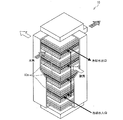
図1は本実施形態に係る燃料電池システム150の概略構成を、図2は燃料電池10の概略構造を、図3は燃料電池10のセル10aの概略構造を、図4はセル10aに、本実施形態に係る温度分布測定装置140が配置されている様子を示している。
1 shows a schematic configuration of a
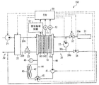
(燃料電池システムの構成)
燃料電池システム150は、水素と酸素との電気化学反応を利用して電力を発生する燃料電池10を備えている。燃料電池システム150は、例えば電気自動車に適用される。燃料電池10は、図示しない電気負荷や2次電池等の電気機器に電力を供給するものである。因みに、電気自動車の場合、車両走行駆動源としての電動モータが電気負荷に相当している。
(Configuration of fuel cell system)
The
本実施形態では燃料電池10として固体高分子電解質型燃料電池を用いており、基本単位となるセル10aが複数個(最大400個程度)積層され、且つ電気的に直列接続されている(図2参照)。セル10aは、図3に示すように、空気(酸素)が供給される空気極(正極)1と、水素が供給される燃料極(負極)2と、空気極1と燃料極2との間に挟持されている電解質膜3とを備えている。また、セル10aは、各セル10aに供給される空気と水素との通路を区切るために、かつ、各セル10aを電気的に接続するためのセパレータ4が設けられている。空気極1および燃料極2は、カーボンからなる電極部分と、例えば白金などの触媒部分とで構成されている。燃料電池10では、以下の水素と酸素との電気化学反応が起こり電気エネルギが発生する。
(負極側)H2→2H++2e−
(正極側)2H++1/2O2+2e−→H2O
そして、燃料電池10の出力電圧を検出する電圧センサ11と燃料電池10の出力電流を検出する電流センサ12とが設けられている。
In this embodiment, a solid polymer electrolyte fuel cell is used as the
(Negative electrode side) H 2 → 2H + + 2e −
(Positive electrode side) 2H + + 1 / 2O 2 + 2e − → H 2 O
A voltage sensor 11 that detects the output voltage of the
積層されたセル10a間には、図4に示すように、セル10a面内の温度分布を測定する温度分布測定装置140が設けられている。温度分布測定装置140は、隣り合うセル10aに挟まれて配置されており、隣り合うセル10aと電気的に直列接続されている。温度分布測定装置140から測定した電位差信号は、後述の信号処理回路51に入力される。温度分布測定装置140については後述する。なお、図4における温度分布測定装置140の位置については単なる一例に過ぎない。
Between the
図1に戻り、燃料電池システム150には、燃料電池10の空気極1側に空気を供給するための空気流路20と、燃料電池10の燃料極2側に水素を供給するための水素流路30とが設けられている。ここで、空気流路20における燃料電池10より上流側を空気供給流路20aといい、下流側を空気排出流路20bという。また、水素流路30における燃料電池10より上流側を水素供給流路30aといい、下流側を水素排出流路30bという。
Returning to FIG. 1, the
空気供給流路20aの最上流部には、大気中から吸入した空気を燃料電池10に圧送するための空気ポンプ21が設けられ、空気供給流路20aにおける空気ポンプ21と燃料電池10との間には、空気への加湿を行う加湿器22が設けられている。また、空気排出流路20bには、燃料電池10内の空気の圧力を調整するための空気調圧弁23が設けられている。
An
水素供給流路30aの最上流部には、水素が充填された高圧水素タンク31が設けられ、水素供給流路30aにおける高圧水素タンク31と燃料電池10との間には、燃料電池10に供給される水素の圧力を調整するための水素調圧弁32が設けられている。
A high-
水素排出流路30bには、水素供給流路30aにおける水素調圧弁32の下流側に接続されて閉ループを構成する水素循環流路30cが分岐して設けられており、これにより水素流路30内で水素を循環させて、未反応の水素を燃料電池10に再供給するようにしている。そして、水素循環流路30cには、水素流路30内で水素を循環させるための水素ポンプ33が設けられている。
The
燃料電池10は発電効率確保のために運転中一定温度(例えば80℃程度)に維持する必要がある。このため、燃料電池10を冷却するための冷却システムが設けられている。冷却システムには、燃料電池10に冷却水(熱媒体)を循環させる冷却水経路40、冷却水を循環させるウォータポンプ41、ファン42を備えたラジエータ(放熱器)43が設けられている。
The
冷却水経路40には、冷却水をラジエータ43をバイパスさせるためのバイパス経路44が設けられている。冷却水経路40とバイパス経路44との合流点には、バイパス経路44に流れる冷却水流量を調整するための流路切替弁45が設けられている。また、冷却水経路40における燃料電池10の出口側近傍には、燃料電池10から流出した冷却水の温度を検出する温度検出手段としての温度センサ46が設けられている。この温度センサ46により冷却水温度を検出することで、燃料電池10の温度を間接的に検出することができる。
The cooling
また、燃料電池システム150には、各種制御を行う制御部(ECU)50が設けられている。制御部50は、CPU、ROM、RAM等からなる周知のマイクロコンピュータとその周辺回路とによって構成されている。そして、制御部50には、電圧センサ11から出力電圧を検出した検出信号、電流センサ12から出力電流を検出した検出信号、および後述する信号処理回路51からの信号が入力される。また、制御部50は、演算結果に基づいて、空気ポンプ21、加湿器22、空気調圧弁23、水素調圧弁32、水素ポンプ33、ウォータポンプ41、流路切替弁45等に制御信号を出力する。
The
また、燃料電池システム150には、温度分布測定装置140から測定された電圧信号を処理する信号処理回路51が設けられている。信号処理回路51は、温度分布測定装置140から電圧センサ(電圧測定部)(不図示)によって測定された電圧信号を演算処理し、上記熱電対の熱起電力特性と室温とからセル10a面内の温度を測定する。信号処理回路51は、測定した温度値を制御部50に出力し、制御部50では、セル10aの面内における温度分布を検出する。また、制御部50は、この検出した温度分布を用いて電流密度分布に対応する分布を生成する。但し、この場合、セル10aの電解質膜3の特性が一様で、セル10a面内の冷却能力が一様である必要はある。なお、特許請求の範囲に記載した、本発明の燃料電池システムにおける演算部は、制御部50および信号処理回路51に相当する。
In addition, the
(温度分布測定装置の構成)
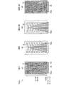
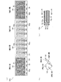
次に、温度分布測定装置140について図5〜図12を用いて説明する。図5は、温度分布測定装置140の一例である温度分布測定装置140aの構成を示しており、(a)はその平面図であり、(b)はその斜視図であり、(c)はその断面図である。なお、図5(a)は、温度分布測定装置140aを分解した状態で示している。
(Configuration of temperature distribution measuring device)
Next, the temperature
温度分布測定装置140aは、3枚の基板141〜143を順に積層した積層基板で構成されている。基板141〜143は、セル10aと同様な形状(例えば長方形状)および寸法を有するが、その一面のサイズは、セル10aと後述する熱電対とが電気的に接続されないようにするために、セル10aのサイズと比較してやや大きく形成されている。具体的には、長方形状である基板141〜143の長辺側の長さをセル10aのそれと比較してやや大きく形成している。なお、特許請求の範囲に記載した、本発明の温度分布測定装置における基板は、基板141〜143を順に積層した積層基板に相当する。
The temperature
基板141〜143としては、プリント基板に使用する、ガラスエポキシ等の絶縁材料、あるいはPET(ポリエチレンテレフタレート)フィルムを用いることができ、本実施形態ではガラスエポキシによって形成した。なお、基板141〜143には、空気、水素、冷却水がそれぞれ通過するマニホールドが形成されているが、ここではその図示を省略している。また、基板141〜143は、絶縁性接着剤を介在させてホットプレスにより一体化されている。
As the
基板141〜143には、セル10aの大きさと同一の範囲に、基板を貫通するスルーホールTH1が形成されている。このスルーホールTH1は、周知のドリルなどによって形成すればよい。基板141には、その表面(基板142と対向する面とは反対側の面)に、かつ、セル10aの大きさと同一の範囲に、電極D1が形成されている。基板143には、その裏面(基板142と対向する面とは反対側の面)に、かつ、セル10aの大きさと同一の範囲に、電極D2が形成されている。電極D1,D2は、温度分布測定装置140がセル10a間に配置されたときに隣接するセル10aと接触し、セル10aと電気的に接続される。また、電極D1,D2は、電極D1,D2の形成材料が埋め込まれたスルーホールTH1によって、互いが電気的に接続される。つまり、電極D1,D2は、セル10aと温度分布測定装置140aとの電気的接続を図るものである。電極D1,D2としては、一般的な電子機器用プリント基板に使用される銅を用いることができ、電解めっき、無電解めっきによって形成すればよい。また、電極D1,D2には、接触抵抗の低減のために、金メッキを施すこともできる。
In the
基板141には、上述のセル10aよりやや大きく形成された部分に、基板を貫通するスルーホールTH2aが形成されるとともに、その表面側に、上記熱電対の電極D3としての金属パターンがスルーホールTH2aから基板端に向かって形成されている。また、基板143には、上述のセル10aよりやや大きく形成された部分に、基板を貫通するスルーホールTH2bが形成されるとともに、その裏面側に、上記熱電対の電極D4としての金属パターンがスルーホールTH2bから基板端に向かって形成されている。
On the
基板142の表面(基板141と対向する面)には、全体的に、金属パターンPaが形成され、この金属パターンPaは、金属パターンPaの形成材料が埋め込まれたスルーホールTH2aと接続されている。また、基板142には、基板を貫通するスルーホールTH2cが形成される。基板143の表面(基板142と対向する面)には、全体的に、金属パターンPbが形成され、この金属パターンPbは、金属パターンPbの形成材料が埋め込まれたスルーホールTH2bと接続されている。金属パターンPa,Pbは、金属パターンPa,Pbのいずれかの形成材料が埋め込まれたスルーホールTH2cによって接続されている。
A metal pattern Pa is entirely formed on the surface of the substrate 142 (a surface facing the substrate 141), and this metal pattern Pa is connected to a through hole TH2a in which a material for forming the metal pattern Pa is embedded. . In addition, a through hole TH2c penetrating the substrate is formed in the
金属パターンPa,PbおよびスルーホールTH2a〜TH2cは、上記熱電対を構成している。電極D3,D4は、上述のように上記熱電対の電極である。金属パターンPa,Pbの形成材料は、熱電対を構成する周知の材料である銅−コンスタンタンを用いることができるが、これに限らず熱起電力が発生する材料であれば用いることができる。スルーホールTH2a〜TH2cは、スルーホールTH1と同様に、周知のドリルなどによって形成すればよい。また、金属パターンPa,Pbは、メッキ法によって形成した後、周知のフォトリソグラフィ技術を用いて整形すればよい。 The metal patterns Pa and Pb and the through holes TH2a to TH2c constitute the thermocouple. The electrodes D3 and D4 are the electrodes of the thermocouple as described above. As a material for forming the metal patterns Pa and Pb, copper-constantan, which is a well-known material constituting a thermocouple, can be used, but not limited thereto, any material that generates a thermoelectromotive force can be used. The through holes TH2a to TH2c may be formed by a well-known drill or the like, similarly to the through hole TH1. Further, the metal patterns Pa and Pb may be formed by using a well-known photolithography technique after being formed by a plating method.
(燃料電池システムの動作)
燃料電池10に水素および空気の供給が開始されることで、燃料電池10の発電が開始される。燃料電池10の発電が開始されたことにより、温度分布測定装置140aにおける、金属パターンPa,PbおよびスルーホールTH2a〜TH2cによって構成した熱電対に熱起電力が発生する。この熱起電力による電圧を図示しない電圧センサによって測定し、この測定した電圧を信号処理回路51に入力する。信号処理回路51は、上記電圧センサによって測定された電圧に基づき、上記熱電対の熱起電力特性と室温とから温度を算出し、測定した温度値を制御部50に出力する。制御部50は、信号処理回路51に入力された温度値に基づき、セル10aの面内における温度分布を検出する。また、制御部50は、この検出した温度分布を用いて電流密度分布に対応する分布を生成する。
(Operation of fuel cell system)
When the supply of hydrogen and air to the
制御部50は、生成したセル10aの面内における温度分布および電流密度分布に対応する分布に基づいて燃料電池10の発電特性を確認し、空気供給制御、冷却制御等を行い、また、発電劣化特性を確認する。燃料電池10では、空気や水素の燃料ガスの出入口における燃料ガスの温度差(特に空気極1において酸素の濃度が下がる)、冷却水出入口における冷却水の温度差などによって発電効率が変化するため、セル10aの面内における温度分布を測定して発電特性を確認する必要がある。また、発電劣化特性は、燃料電池10が劣化すると、同一電流密度において、発電量が低下し、発熱量が増加するため、セル10aの面内における温度分布を測定することで確認することができる。また、温度分布測定装置140は、以上のような制御に用いられるため、セル10aにおいてセル数枚の間隔で挿入されることが好ましい。また、このため、上記熱電対は、30×10cm2のセル10aの面内に100点ほど構成することが好ましい。
The
以上のように、本実施形態における温度分布測定装置140は、基板に熱電対を構成する金属パターンPa,Pb等を設けて温度測定を行うために薄型化・軽量化が可能であり、それゆえ温度分布測定装置140がセル10a間に配置されていても燃料電池10の薄型・軽量を実現できる。これにより、燃料電池10が搭載された電気自動車において、その運動性能を確保することができる。
As described above, the temperature
また、基板を積層基板としてその内層に金属パターンPa,Pbを設け、かつ、上記基板のサイズを大きくして上記熱電対の電極D3,D4等を形成することで、上記熱電対がセル10a、および上記基板とセル10aとの電気的接続のための電極D1,D2と電気的に接続されないように構成している。この構成により、燃料電池10の発電に悪影響を及ぼすことなく温度測定を行うことができる。また、以上の構成により、燃料電池10の内部抵抗を高めることを防いで、燃料電池10の発電に悪影響を及ぼすことなく温度測定を行うことができる。
Further, the substrate is a laminated substrate, and metal patterns Pa and Pb are provided in the inner layer, and the size of the substrate is increased to form the electrodes D3 and D4 of the thermocouple. And it is comprised so that it may not electrically connect with the electrodes D1 and D2 for the electrical connection of the said board | substrate and the
また、温度分布測定装置140では、温度測定の際に、電極D1,D2面方向の熱伝導による影響が懸念されるが、電極D1,D2は隣接するセル10aに接触するため、比較的短時間で熱平衡状態となり、それゆえ温度測定の信頼性は確保できる。また、燃料電池では、水素漏洩の防止のためセル間での充分な気密が必要であり、そのために約400kgの締結加重でセルの面方向に力が加えられている。そのため、この力によって電極D1,D2には弾性変形が生じ、これにより、電極D1,D2と熱電対との間では良好な熱接触が得られ、この点からも温度測定の信頼性は確保できる。
In the temperature
また、本実施形態における燃料電池システム150は、温度分布測定装置140により得られた温度分布および電流密度分布に対応する分布に基づいて燃料電池10の発電状態を推定し、空気供給制御、冷却制御等を行い、また、発電劣化特性を確認することができる。このように、燃料電池システム150は、温度分布測定装置140を備えて各種制御を行えるために、従来の燃料電池システムと比較して、薄型化・軽量化を維持しつつも、燃料電池システムの効率および信頼性をより大きく向上させることができる。
In addition, the
(温度分布測定装置の構成例)
図6は、温度分布測定装置140aの変更例である温度分布測定装置140aaの構成を示している。
(Configuration example of temperature distribution measuring device)
FIG. 6 shows a configuration of a temperature distribution measuring device 140aa which is a modified example of the temperature
温度分布測定装置140aでは、上述のように、長方形状である基板141〜143の長辺側の長さをセル10aのそれと比較してやや大きく形成している。これに対し、温度分布測定装置140aaは、温度分布測定装置140aと同様の構成を有しているが、同図に示すように、基板141〜143の長辺側の長さをセル10aのそれと比較して一部のみやや大きく形成し、その部分に電極D3,D4およびスルーホールTH2a,TH2bなどを設けている。換言すれば、電極D3,D4およびスルーホールTH2a,TH2bなどを一箇所に集めて設け、その箇所だけ基板を大きく形成する。
In the temperature
図7は、温度分布測定装置140の他の例である温度分布測定装置140bの構成を示している。なお、図7は、温度分布測定装置140bを分解した状態で示している。また、説明の便宜上、温度分布測定装置140aの部材と同一の機能を有する部材には同一の部材番号を付している。
FIG. 7 shows a configuration of a temperature
温度分布測定装置140bは、3枚の基板141a〜143aを順に積層した積層基板で構成されている。基板141a〜143aは、セル10aと同様な形状(例えば長方形状)および寸法を有するが、その一面のサイズは、セル10aと後述する熱電対とが電気的に接続されないようにするために、セル10aのサイズと比較してやや大きく形成されている。具体的には、長方形状である基板141a〜143aの短辺側の長さをセル10aのそれと比較してやや大きく形成している。温度分布測定装置140bは、この点について、また、この点による金属パターンの変更(詳細は後述)のみが、温度分布測定装置140aとは異なっている。
The temperature
基板141a〜143aとしては、プリント基板に使用する、ガラスエポキシ等の絶縁材料、あるいはPETフィルムを用いることができ、本実施形態ではガラスエポキシによって形成した。なお、基板141a〜143aには、空気、水素、冷却水がそれぞれ通過するマニホールドが形成されているが、ここではその図示を省略している。また、基板141a〜143aは、絶縁性接着剤を介在させてホットプレスにより一体化されている。
As the
基板141a〜143aには、セル10aの大きさと同一の範囲に、基板を貫通するスルーホールTH1が形成されている。このスルーホールTH1は、周知のドリルなどによって形成すればよい。基板141aには、その表面(基板142aと対向する面とは反対側の面)に、かつ、セル10aの大きさと同一の範囲に、電極D1が形成されている。基板143aには、その裏面(基板142aと対向する面とは反対側の面)に、かつ、セル10aの大きさと同一の範囲に、電極D2が形成されている。電極D1,D2は、温度分布測定装置140bがセル10a間に配置されたときに隣接するセル10aと接触し、セル10aと電気的に接続される。また、電極D1,D2は、電極D1,D2の形成材料が埋め込まれたスルーホールTH1によって、互いが電気的に接続される。つまり、電極D1,D2は、セル10aと温度分布測定装置140bとの電気的接続を図るものである。電極D1,D2としては、一般的な電子機器用プリント基板に使用される銅を用いることができ、電解めっき、無電解めっきによって形成すればよい。また、電極D1,D2には、接触抵抗の低減のために、金メッキを施すこともできる。
Through holes TH1 penetrating the substrate are formed in the
基板141aには、上述のセル10aよりやや大きく形成された部分に、基板を貫通するスルーホールTH2aが形成されるとともに、その表面側に、上記熱電対の電極D3としての金属パターンがスルーホールTH2aから基板端に向かって形成されている。また、基板143aには、上述のセル10aよりやや大きく形成された部分に、基板を貫通するスルーホールTH2bが形成されるとともに、その裏面側に、上記熱電対の電極D4としての金属パターンがスルーホールTH2bから基板端に向かって形成されている。
In the
基板142aの表面(基板141aと対向する面)には、全体的に、金属パターンPaaが形成され、この金属パターンPaaは、金属パターンPaaの形成材料が埋め込まれたスルーホールTH2aと接続されている。また、基板142aには、基板を貫通するスルーホールTH2cが形成される。基板143aの表面(基板142aと対向する面)には、全体的に、金属パターンPbaが形成され、この金属パターンPbaは、金属パターンPbaの形成材料が埋め込まれたスルーホールTH2bと接続されている。金属パターンPaa,Pbaは、金属パターンPaa,Pbaのいずれかの形成材料が埋め込まれたスルーホールTH2cによって接続されている。
A metal pattern Paa is formed on the entire surface of the
金属パターンPaa,PbaおよびスルーホールTH2a〜TH2cは、上記熱電対を構成している。電極D3,D4は、上述のように上記熱電対の電極である。金属パターンPaa,Pbaの形成材料は、熱電対を構成する周知の材料である銅−コンスタンタンを用いることができるが、これに限らず熱起電力が発生する材料であれば用いることができる。スルーホールTH2a〜TH2cは、スルーホールTH1と同様に、周知のドリルなどによって形成すればよい。また、金属パターンPaa,Pbaは、メッキ法によって形成した後、周知のフォトリソグラフィ技術を用いて整形すればよい。金属パターンPaa,Pbaは、温度分布測定装置140aにおける金属パターンPa,Pbに対し、基板141a〜143aの短辺側の長さをやや大きく形成していることによってその形状を変更した点のみが異なるものである。
The metal patterns Paa and Pba and the through holes TH2a to TH2c constitute the thermocouple. The electrodes D3 and D4 are the electrodes of the thermocouple as described above. As a material for forming the metal patterns Paa and Pba, copper-constantan, which is a well-known material constituting a thermocouple, can be used, but not limited to this, any material that generates a thermoelectromotive force can be used. The through holes TH2a to TH2c may be formed by a well-known drill or the like, similarly to the through hole TH1. The metal patterns Paa and Pba may be formed by a plating method and then shaped using a well-known photolithography technique. The metal patterns Paa and Pba are different from the metal patterns Pa and Pb in the temperature
温度分布測定装置140bよる温度分布測定方法ならびに効果については、温度分布測定装置140aによるそれと同様であるので、ここではその説明を省略する。
Since the temperature distribution measuring method and effect by the temperature
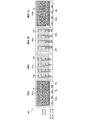
次に、図8は、温度分布測定装置140bの変更例である温度分布測定装置140baの構成を示している。
Next, FIG. 8 shows a configuration of a temperature distribution measuring device 140ba which is a modified example of the temperature
温度分布測定装置140baは、同図に示すように、温度分布測定装置140aaと同様に、電極D3,D4およびスルーホールTH2a,TH2bを一箇所に集めて設け、その箇所のみ基板を大きく形成している。なお、温度分布測定装置140baでは、上記箇所に合わせて金属パターンPaa,Pbaの形成状態も変更しているため、上記箇所以外の箇所もやや大きく形成している。 As shown in the figure, the temperature distribution measuring device 140ba is provided with the electrodes D3 and D4 and the through holes TH2a and TH2b gathered in one place, and a large substrate is formed only at that place, as with the temperature distribution measuring device 140aa. Yes. In the temperature distribution measuring device 140ba, since the formation state of the metal patterns Paa and Pba is changed in accordance with the above-mentioned places, the places other than the above-mentioned places are formed slightly larger.
次に、図9は、温度分布測定装置140の他の例である温度分布測定装置140cの構成を示しており、(a)はその平面図であり、(b)は温度分布測定装置140cにおける基板145,146を積層する様子を示す図であり、(c)はその断面図である。なお、説明の便宜上、温度分布測定装置140a,140bの部材と同一の機能を有する部材には同一の部材番号を付し、その説明を省略する。
Next, FIG. 9 shows a configuration of a temperature
温度分布測定装置140cは、2枚の基板145,146を順に積層した積層基板で構成されている。基板145は、基板141aと同様な構成であるが、その裏面(基板146と対向する面)に金属パターンPaaが形成されている。基板146は、基板143aと同様な構成である。温度分布測定装置140bにおけるスルーホールTH2cは形成されない。
The temperature
温度分布測定装置140cよる温度測定方法ならびに効果については、温度分布測定装置140aによるそれと同様であるので、ここではその説明を省略する。但し、温度分布測定装置140cは、温度分布測定装置140a,140bと比較して構成が簡素化されているので、より薄型化・軽量化を実現できるとともに、より燃料電池10の内部抵抗を高めることを防いで、燃料電池10の発電に悪影響を及ぼすことなく温度測定を行うことができる。
Since the temperature measurement method and effect by the temperature
次に、図10は、温度分布測定装置140cの変更例である温度分布測定装置140caの構成を示している。
Next, FIG. 10 shows a configuration of a temperature distribution measuring device 140ca that is a modified example of the temperature
温度分布測定装置140caは、同図に示すように、温度分布測定装置140baと同様に、電極D3,D4およびスルーホールTH2a,TH2bを一箇所に集めて設け、その箇所だけ基板を大きく形成している。なお、温度分布測定装置140caでは、上記箇所に合わせて金属パターンPaa,Pbaの形成状態も変更しているため、上記箇所以外の箇所もやや大きく形成している。 As shown in the figure, the temperature distribution measuring device 140ca is provided with the electrodes D3 and D4 and the through holes TH2a and TH2b gathered in one place, and the substrate is greatly formed only in that place, as with the temperature distribution measuring device 140ba. Yes. In the temperature distribution measuring device 140ca, the formation state of the metal patterns Paa and Pba is changed in accordance with the above locations, so that the locations other than the above locations are formed slightly larger.
次に、図11(a)は温度分布測定装置140の他の例である温度分布測定装置140dの構成を示しており、図11(b)は温度分布測定装置140の他の例である温度分布測定装置140eの構成を示している。なお、説明の便宜上、温度分布測定装置140a〜140cの部材と同一の機能を有する部材には同一の部材番号を付し、その説明を省略する。
Next, FIG. 11A shows a configuration of a temperature
温度分布測定装置140dは、温度分布測定装置140a,140bにおける電極D1,D2に代えて、導体A,Bによって積層基板を挟みこむとともに、スルーホールTH1を貫通孔に変更して、当該貫通孔を導体A,Bのいずれかによって埋め込んでいる。温度分布測定装置140eは、温度分布測定装置140cにおける電極D1,D2に代えて、導体A,Bによって積層基板を挟みこむとともに、スルーホールTH1を貫通孔に変更して、当該貫通孔を導体A,Bのいずれかによって埋め込んでいる。このような構成とすることにより、導体A,Bに溝を形成すればセパレータ4として使用することができるため、温度分布測定装置140a〜140cと比較して、より薄型化・軽量化を実現できる。
The temperature
(燃料電池評価装置)
次に、本実施形態に係る燃料電池評価装置200について、図12を用いて説明する。図12は、燃料電池評価装置200の概略構成を示している。燃料電池評価装置200は、温度分布測定装置140を用い、燃料電池の適切な発電条件および燃料電池の温度特性の試験、ならびに発電による劣化の解析などを行う。
(Fuel cell evaluation device)
Next, the fuel
燃料電池評価装置200は、一般的な燃料電池評価装置と同様の構成・機能を有するものであるが、簡単に説明すると、温度分布測定装置140を用いた燃料電池(FC)201と、燃料電池201に燃料ガスを供給するガスライン202と、ガスライン202上に設けられ、上記燃料ガスの流量を制御するマスフローコントローラ203と、燃料電池201に冷却水を供給する/燃料電池201から冷却水を排出する冷却水ライン204とを備えている。上記燃料ガスとしては、水素、空気(酸素)、および窒素であり、当該窒素は、水素および空気に加えられる。また、上記窒素は、起電力が発生しないようにパージ用にも使用される。
The fuel
また、燃料電池評価装置200は、上記窒素が加えられた水素のガスライン202上、および上記窒素が加えられた空気のガスライン202上に設けられ、燃料電池201における電解質膜の加湿量を制御するための加湿器205と、加湿器205の後段に設けられ、燃料電池201に加えられる空気および水素の温度を制御するためのヒータ206と、ヒータ206と燃料電池201の燃料入口との間、および燃料電池201の燃料出口に設けられる、温度センサ(TC)、湿度センサ(DP)、および圧力センサ(P)などのセンサ類207と、燃料電池201に接続され、モータや電動機などの負荷を模擬して、発電状況を再現する電子負荷(EL)208と、燃料電池201の燃料出口から排出されたガスを冷却し、発生した水蒸気・水分を液化させる熱交換器209と、熱交換器209にて液化させた水分を分析・軽量する生成水回収器210とを備えている。なお、センサ類207は、試験の内容によって、設けるセンサ、設ける場所が変更される。
The fuel
また、燃料電池評価装置200は、温度分布測定装置140における熱電対から電圧を測定する電圧センサ(電圧測定部)(不図示)と、当該電圧センサによって測定された電圧信号を演算処理し、上記熱電対の熱起電力特性と室温とから燃料電池201のセル面内の温度を測定するとともに、この測定した温度値から上記セル面内における温度分布を検出する。そして、この検出した温度分布を用いて一般的な手法により上記試験ならびに上記劣化解析などの燃料電池201の性能評価を行う評価部(不図示)とを備えている。
Further, the fuel
本発明は上述した各実施形態に限定されるものではなく、請求項に示した範囲で種々の変更が可能であり、異なる実施形態にそれぞれ開示された技術的手段を適宜組み合わせて得られる実施形態についても本発明の技術的範囲に含まれる。 The present invention is not limited to the above-described embodiments, and various modifications are possible within the scope shown in the claims, and embodiments obtained by appropriately combining technical means disclosed in different embodiments. Is also included in the technical scope of the present invention.
本発明に係る温度分布測定装置は、燃料電池の薄型・小型を維持し、かつ、燃料電池の内部抵抗を高めることを防いで発電に悪影響を及ぼすことなくセル面内の温度分布を測定可能であるから、上記温度分布測定装置は、発電特性や発電劣化特性の確認などのために、燃料電池システムおよび燃料電池評価装置に好適に用いることができる。また、上記温度分布測定装置を備える燃料電池システムは、自動車に好適に用いることができる。 The temperature distribution measuring apparatus according to the present invention can measure the temperature distribution in the cell plane without adversely affecting power generation by keeping the fuel cell thin and small and preventing the internal resistance of the fuel cell from being increased. Therefore, the temperature distribution measuring device can be suitably used for a fuel cell system and a fuel cell evaluation device for confirmation of power generation characteristics and power generation deterioration characteristics. Moreover, a fuel cell system provided with the said temperature distribution measuring apparatus can be used suitably for a motor vehicle.
4 セパレータ
10 燃料電池
10a 燃料電池のセル
50 制御部(演算部)
51 信号処理回路(演算部)
140 温度分布測定装置
150 燃料電池システム
200 燃料電池評価装置
D1、D2 電極
Pa、Paa、Pb、Pba 金属パターン
4
51 Signal processing circuit (calculation unit)
140 Temperature
Claims (5)
複数の絶縁体を積層してなる基板と、
上記基板の両面に上記セルに接触するように設けられ、かつ互いが電気的に接続されている一対の電極と、
上記基板における内層に形成され、かつ、上記セルおよび上記電極とは電気的に接続されていない、熱電対を構成する複数の金属パターンとを備えていることを特徴とする温度分布測定装置。 A temperature distribution measuring device that is disposed between stacked cells of a fuel cell and measures the temperature distribution in the cell plane,
A substrate formed by laminating a plurality of insulators;
A pair of electrodes provided on both sides of the substrate in contact with the cell and electrically connected to each other;
A temperature distribution measuring apparatus comprising: a plurality of metal patterns forming a thermocouple that are formed in an inner layer of the substrate and are not electrically connected to the cell and the electrode.
上記温度分布測定装置における熱電対から電圧を測定する電圧測定部と、
上記電圧測定部にて測定された電圧に基づき、上記熱電対の熱起電力特性と室温とから温度を算出するとともに、当該算出した温度に基づき温度分布を生成する演算部とを備えていることを特徴とする燃料電池システム。 A fuel cell arranged between cells in which the temperature distribution measuring device according to any one of claims 1 to 3 is stacked;
A voltage measuring unit for measuring a voltage from a thermocouple in the temperature distribution measuring device;
Based on the voltage measured by the voltage measurement unit, a temperature is calculated from the thermoelectromotive force characteristics of the thermocouple and room temperature, and a calculation unit is provided that generates a temperature distribution based on the calculated temperature. A fuel cell system.
燃料電池の積層されたセル間に配置されている、請求項1〜3のいずれか一項に記載の温度分布測定装置における熱電対から電圧を測定する電圧測定部と、
上記電圧測定部にて測定された電圧に基づき、上記熱電対の熱起電力特性と室温とから温度を算出するとともに、当該算出した温度に基づき温度分布を生成し、この生成した温度分布を用いて上記燃料電池の性能評価を行う評価部とを備えていることを特徴とする燃料電池評価装置。 A fuel cell evaluation device for evaluating the performance of a fuel cell,
A voltage measuring unit that measures a voltage from a thermocouple in the temperature distribution measuring device according to any one of claims 1 to 3, which is disposed between the stacked cells of the fuel cell,
Based on the voltage measured by the voltage measuring unit, the temperature is calculated from the thermoelectromotive force characteristics of the thermocouple and the room temperature, and a temperature distribution is generated based on the calculated temperature, and the generated temperature distribution is used. And a fuel cell evaluation apparatus comprising: an evaluation unit that performs performance evaluation of the fuel cell.
Priority Applications (1)
| Application Number | Priority Date | Filing Date | Title |
|---|---|---|---|
| JP2008182409A JP5090277B2 (en) | 2008-07-14 | 2008-07-14 | Temperature distribution measuring device, fuel cell system, and fuel cell evaluation device |
Applications Claiming Priority (1)
| Application Number | Priority Date | Filing Date | Title |
|---|---|---|---|
| JP2008182409A JP5090277B2 (en) | 2008-07-14 | 2008-07-14 | Temperature distribution measuring device, fuel cell system, and fuel cell evaluation device |
Publications (2)
| Publication Number | Publication Date |
|---|---|
| JP2010021096A true JP2010021096A (en) | 2010-01-28 |
| JP5090277B2 JP5090277B2 (en) | 2012-12-05 |
Family
ID=41705770
Family Applications (1)
| Application Number | Title | Priority Date | Filing Date |
|---|---|---|---|
| JP2008182409A Expired - Fee Related JP5090277B2 (en) | 2008-07-14 | 2008-07-14 | Temperature distribution measuring device, fuel cell system, and fuel cell evaluation device |
Country Status (1)
| Country | Link |
|---|---|
| JP (1) | JP5090277B2 (en) |
Cited By (4)
| Publication number | Priority date | Publication date | Assignee | Title |
|---|---|---|---|---|
| CN102157743A (en) * | 2011-02-18 | 2011-08-17 | 北京工业大学 | Transient temperature distribution sensor in fuel cell |
| WO2012081872A2 (en) * | 2010-12-13 | 2012-06-21 | 두산중공업 주식회사 | Device for measuring the temperature distribution of a fuel cell |
| KR101283022B1 (en) | 2011-06-10 | 2013-07-08 | 현대자동차주식회사 | Fuel cell stack |
| JP2014203710A (en) * | 2013-04-05 | 2014-10-27 | トヨタ自動車株式会社 | Fuel cell inspection instrument and inspection device using the same |
Citations (7)
| Publication number | Priority date | Publication date | Assignee | Title |
|---|---|---|---|---|
| JPS6296831A (en) * | 1985-10-23 | 1987-05-06 | Eikou Seiki Sangyo Kk | Heat flowmeter sensor and manufacture thereof |
| JPH07249423A (en) * | 1994-03-10 | 1995-09-26 | Toshiba Corp | Fuel cell power generating device |
| JPH09223512A (en) * | 1996-02-16 | 1997-08-26 | Fuji Electric Co Ltd | Abnormality monitoring method of fuel cell and device therefor |
| JP2003014553A (en) * | 2001-06-27 | 2003-01-15 | Denso Corp | Temperature sensor and its manufacturing method |
| JP2006331731A (en) * | 2005-05-24 | 2006-12-07 | Kri Inc | Film-electrode assembly and polymer electrolyte fuel cell using the same |
| JP2007242339A (en) * | 2006-03-07 | 2007-09-20 | Nissan Motor Co Ltd | Fuel cell system, humidity degree measuring method of fuel cell, and purge control method of fuel cell |
| JP2007280643A (en) * | 2006-04-03 | 2007-10-25 | Denso Corp | Current measuring device |
-
2008
- 2008-07-14 JP JP2008182409A patent/JP5090277B2/en not_active Expired - Fee Related
Patent Citations (7)
| Publication number | Priority date | Publication date | Assignee | Title |
|---|---|---|---|---|
| JPS6296831A (en) * | 1985-10-23 | 1987-05-06 | Eikou Seiki Sangyo Kk | Heat flowmeter sensor and manufacture thereof |
| JPH07249423A (en) * | 1994-03-10 | 1995-09-26 | Toshiba Corp | Fuel cell power generating device |
| JPH09223512A (en) * | 1996-02-16 | 1997-08-26 | Fuji Electric Co Ltd | Abnormality monitoring method of fuel cell and device therefor |
| JP2003014553A (en) * | 2001-06-27 | 2003-01-15 | Denso Corp | Temperature sensor and its manufacturing method |
| JP2006331731A (en) * | 2005-05-24 | 2006-12-07 | Kri Inc | Film-electrode assembly and polymer electrolyte fuel cell using the same |
| JP2007242339A (en) * | 2006-03-07 | 2007-09-20 | Nissan Motor Co Ltd | Fuel cell system, humidity degree measuring method of fuel cell, and purge control method of fuel cell |
| JP2007280643A (en) * | 2006-04-03 | 2007-10-25 | Denso Corp | Current measuring device |
Cited By (6)
| Publication number | Priority date | Publication date | Assignee | Title |
|---|---|---|---|---|
| WO2012081872A2 (en) * | 2010-12-13 | 2012-06-21 | 두산중공업 주식회사 | Device for measuring the temperature distribution of a fuel cell |
| WO2012081872A3 (en) * | 2010-12-13 | 2012-10-04 | 두산중공업 주식회사 | Device for measuring the temperature distribution of a fuel cell |
| US9354127B2 (en) | 2010-12-13 | 2016-05-31 | Doosan Heavy Industries & Construction Co., Ltd. | Device for measuring temperature distribution of fuel cell |
| CN102157743A (en) * | 2011-02-18 | 2011-08-17 | 北京工业大学 | Transient temperature distribution sensor in fuel cell |
| KR101283022B1 (en) | 2011-06-10 | 2013-07-08 | 현대자동차주식회사 | Fuel cell stack |
| JP2014203710A (en) * | 2013-04-05 | 2014-10-27 | トヨタ自動車株式会社 | Fuel cell inspection instrument and inspection device using the same |
Also Published As
| Publication number | Publication date |
|---|---|
| JP5090277B2 (en) | 2012-12-05 |
Similar Documents
| Publication | Publication Date | Title |
|---|---|---|
| JP4967421B2 (en) | Current measuring device | |
| JP5186986B2 (en) | Fuel cell impedance measurement device | |
| JP5146225B2 (en) | Current measuring device | |
| JP2009081117A (en) | Current density distribution sensor, manufacturing method thereof, and fuel cell system | |
| JP5488162B2 (en) | Current distribution measuring device, abnormality handling method thereof, and fuel cell system | |
| JP2010103071A (en) | Current measuring device | |
| JP5090277B2 (en) | Temperature distribution measuring device, fuel cell system, and fuel cell evaluation device | |
| US9660283B2 (en) | Current measurement device | |
| JP5494436B2 (en) | Current measuring device | |
| JP4967381B2 (en) | Fuel cell system, fuel cell wetness measuring method, fuel cell purge control method | |
| JP5206258B2 (en) | Current measuring device | |
| JP5987639B2 (en) | Current measuring device | |
| JP2012058180A (en) | Gas concentration measuring apparatus | |
| JP2010080174A (en) | Resistance value measuring device | |
| JP5555976B2 (en) | Current measuring device | |
| JP5708219B2 (en) | Current measuring device | |
| JP2009016157A (en) | Current measurement device | |
| JP5605213B2 (en) | Fuel cell impedance measurement device | |
| JP6459873B2 (en) | Current measuring device | |
| JP5076953B2 (en) | CURRENT MEASURING DEVICE, FUEL CELL MANUFACTURING METHOD, AND FUEL CELL SYSTEM | |
| JP5141286B2 (en) | Fuel cell system | |
| JP6350066B2 (en) | Current measuring device | |
| JP6120078B2 (en) | Current measuring device | |
| JP7174680B2 (en) | Separator, power generation cell, fuel cell stack and liquid detection device | |
| JP2008123960A (en) | Fuel cell |
Legal Events
| Date | Code | Title | Description |
|---|---|---|---|
| A621 | Written request for application examination |
Free format text: JAPANESE INTERMEDIATE CODE: A621 Effective date: 20100225 |
|
| A131 | Notification of reasons for refusal |
Free format text: JAPANESE INTERMEDIATE CODE: A131 Effective date: 20120703 |
|
| A521 | Request for written amendment filed |
Free format text: JAPANESE INTERMEDIATE CODE: A523 Effective date: 20120809 |
|
| TRDD | Decision of grant or rejection written | ||
| A01 | Written decision to grant a patent or to grant a registration (utility model) |
Free format text: JAPANESE INTERMEDIATE CODE: A01 Effective date: 20120904 |
|
| A01 | Written decision to grant a patent or to grant a registration (utility model) |
Free format text: JAPANESE INTERMEDIATE CODE: A01 |
|
| A61 | First payment of annual fees (during grant procedure) |
Free format text: JAPANESE INTERMEDIATE CODE: A61 Effective date: 20120912 |
|
| FPAY | Renewal fee payment (event date is renewal date of database) |
Free format text: PAYMENT UNTIL: 20150921 Year of fee payment: 3 |
|
| R150 | Certificate of patent or registration of utility model |
Ref document number: 5090277 Country of ref document: JP Free format text: JAPANESE INTERMEDIATE CODE: R150 Free format text: JAPANESE INTERMEDIATE CODE: R150 |
|
| R250 | Receipt of annual fees |
Free format text: JAPANESE INTERMEDIATE CODE: R250 |
|
| R250 | Receipt of annual fees |
Free format text: JAPANESE INTERMEDIATE CODE: R250 |
|
| R250 | Receipt of annual fees |
Free format text: JAPANESE INTERMEDIATE CODE: R250 |
|
| R250 | Receipt of annual fees |
Free format text: JAPANESE INTERMEDIATE CODE: R250 |
|
| R250 | Receipt of annual fees |
Free format text: JAPANESE INTERMEDIATE CODE: R250 |
|
| R250 | Receipt of annual fees |
Free format text: JAPANESE INTERMEDIATE CODE: R250 |
|
| LAPS | Cancellation because of no payment of annual fees |