JP2010020573A - System for managing life cycle of equipment and method therefor - Google Patents
System for managing life cycle of equipment and method therefor Download PDFInfo
- Publication number
- JP2010020573A JP2010020573A JP2008180887A JP2008180887A JP2010020573A JP 2010020573 A JP2010020573 A JP 2010020573A JP 2008180887 A JP2008180887 A JP 2008180887A JP 2008180887 A JP2008180887 A JP 2008180887A JP 2010020573 A JP2010020573 A JP 2010020573A
- Authority
- JP
- Japan
- Prior art keywords
- equipment
- deterioration
- facility
- degree
- installation
- Prior art date
- Legal status (The legal status is an assumption and is not a legal conclusion. Google has not performed a legal analysis and makes no representation as to the accuracy of the status listed.)
- Pending
Links
Images


Classifications
-
- Y04S10/54—
Abstract
Description
本発明は、設備を保守・点検するための技術に係り、特に配電設備を保守・点検するための技術に関する。 The present invention relates to a technique for maintaining / inspecting equipment, and more particularly to a technique for maintaining / inspecting power distribution equipment.
配電設備は、一度使用したものを保守、点検し、全く異なった場所にて再度使いまわすという特色がある。従来の設備保守、点検作業は、その対象とする設備については、担当地域についてエリアわけを行い、エリアごとに順次点検するという方法によって実施していた。 Distribution equipment is characterized by maintaining and inspecting what has been used once and then reusing it at a completely different location. Conventional facility maintenance and inspection work is performed by a method in which the target facility is divided into areas for the area in charge and sequentially inspected for each area.
従来の設備保守、点検作業は、エリアごとに順次点検するため、設備の劣化度を意識しておらず、新しいもの、古いものに関わらず点検を実施しており、非効率であった。また、その点検作業ごとに修理コストもばらつきが生じ、経営上問題視されていた。 The conventional equipment maintenance and inspection work is inefficient because it is inspected for each area sequentially, and is not aware of the degree of deterioration of the equipment, and checks whether it is new or old. In addition, the repair cost varies depending on the inspection work, which has been regarded as a management problem.
本発明の目的は、各配電設備の劣化度に基づいて、保守、点検すべき対象の配電設備を選択することで、効率的な作業が可能となるシステムおよび方法を提供することである。 An object of the present invention is to provide a system and a method that enable efficient work by selecting a distribution facility to be maintained and inspected based on the degree of deterioration of each distribution facility.
また、本発明の目的は、点検作業ごとの作業量、コスト、人件費や修理コストについて平準化することができるシステムおよび方法を提供することである。 Moreover, the objective of this invention is providing the system and method which can equalize about the work amount for every inspection work, cost, a labor cost, and repair cost.
また、本発明の目的は、各設備の劣化度情報を蓄積することで、各劣化要素の重要度や設備、部品の耐久度の算出精度を向上させることができるシステムおよび方法を提供することである。 In addition, an object of the present invention is to provide a system and method that can improve the calculation accuracy of the importance of each deterioration factor and the durability of equipment and parts by accumulating the deterioration degree information of each equipment. is there.
上記の課題を解決するためには、本発明では、各設備の設置場所および各設置場所での設置期間から各設備の劣化度を算出し、設備に対する作業時点での劣化度が耐久度を越える設備または設備を同じ設置場所で使用しつづけた場合に設備に対する次回の作業時点での劣化度が耐久度を越える設備の少なくとも1つを、優先的に保守、点検すべき設備として出力することを特徴とする。 In order to solve the above problems, in the present invention, the degree of deterioration of each equipment is calculated from the installation location of each equipment and the installation period at each installation place, and the degree of deterioration at the time of work on the equipment exceeds the durability. If the equipment or equipment continues to be used at the same installation location, output at least one of the equipment whose deterioration level exceeds the durability at the time of the next work on the equipment as the equipment to be preferentially maintained and inspected. Features.
本発明によれば、各配電設備の劣化度から保守、点検すべき優先度を算出することができ、優先度の高い配電設備を対象に保守、点検することで、効率的な作業が可能となる。 According to the present invention, priority to be maintained and inspected can be calculated from the degree of deterioration of each distribution facility, and efficient work is possible by maintaining and inspecting distribution facilities with high priority. Become.
また、本発明によれば、点検作業ごとの作業量、コスト、人件費や修理コストについて平準化することができる。 Further, according to the present invention, it is possible to level the work amount, cost, labor cost, and repair cost for each inspection work.
また、本発明によれば、各設備の劣化度情報を蓄積することで、各劣化要素の重要度や設備、部品の耐久度の算出精度を向上させることができる。 Further, according to the present invention, by accumulating the deterioration degree information of each facility, it is possible to improve the calculation accuracy of the importance of each deterioration element and the durability of each facility and component.
本発明では、使いまわしも含めたその設備について設置環境をもとに劣化度を算出し、保守、点検すべき優先度が判断可能な情報を提供し、その優先度に応じて、保守、点検すればよい。こうすることで、故障しやすい状態の設備から優先的に保守、点検することができる。加えて、余分な点検作業を省くことができる。 In the present invention, the degree of deterioration is calculated based on the installation environment for the equipment including re-use, and information that can determine the priority to be maintained and inspected is provided, and maintenance and inspection are performed according to the priority. do it. By doing so, it is possible to preferentially maintain and inspect equipment that is prone to failure. In addition, extra inspection work can be omitted.
保守、点検すべき優先度を判断するためには、設定されている設備の詳細情報を管理する設備情報管理機能、故障した設備情報を管理する故障履歴管理機能、塩害、雷害といった設備の劣化要素情報を管理する劣化要素管理機能、設備情報および劣化要素情報を入力として各設備の劣化度を算出する設備劣化度算出機能、故障履歴情報および劣化要素情報を入力として各設備の耐久限度を算出するリミット算出機能、劣化要素の各項目の劣化単価を算出する劣化度設定機能、設備情報および劣化度より保守、点検すべき優先度を付与する保守点検優先度表示機能からなるコンピュータシステムを用いる。
以下、本発明の実施の形態について図面により詳細に説明する。
In order to determine the priority to be maintained and inspected, the equipment information management function that manages the detailed information on the set equipment, the fault history management function that manages faulty equipment information, the deterioration of equipment such as salt damage and lightning damage Degradation element management function to manage element information, facility deterioration degree calculation function to calculate the degree of deterioration of each facility using facility information and deterioration element information as input, failure history information and deterioration element information as inputs to calculate durability limit of each facility A computer system is used which includes a limit calculation function to perform, a deterioration level setting function for calculating a deterioration unit price of each item of deterioration elements, and a maintenance inspection priority display function for giving priority to be maintained and inspected based on the facility information and the deterioration level.
Hereinafter, embodiments of the present invention will be described in detail with reference to the drawings.
図1は、本発明を適用した設備管理システムのシステムイメージを示したものである。図1において、100は、設備管理システムである。設備管理システムとして独立させているが、既存の配電系システムと同一システム内でもよい。設備管理システム100は、故障履歴データベース110、設備情報データベース120、劣化要素データベース130、設備耐久度データベース140、設備情報管理機能150、故障履歴管理機能160、劣化要素管理機能170、設備劣化度算出機能180、リミット算出機能190、劣化度設定機能200、保守点検優先度表示機能210を有する。
FIG. 1 shows a system image of an equipment management system to which the present invention is applied. In FIG. 1, 100 is an equipment management system. Although it is made independent as an equipment management system, it may be in the same system as an existing distribution system. The
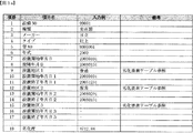
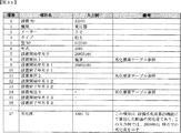
設備情報管理機能150は、設備の設置、撤去、再設置時にその設備に関する情報を設備情報データベース120に登録する。図3bに、設備情報データベースのデータ構成図を示す。設備情報データベース120は、「設備NO」、「種類」、「メーカー」、「タイプ」、「型NO」、「年式」、「設置開始年月日」、「故障年月日」、「設置地区1」、「設置開始年月日1」、「設置終了年月日1」、「設置地区2」、「設置開始年月日2」、「設置終了年月日2」、「設置地区3」、「設置開始年月日3」、「設置終了年月日3」、・・・、「劣化度」を保持する。
The facility
故障履歴管理機能170は、故障した設備を故障履歴データベース110に登録する。図3aに、故障履歴データベース110のデータ構成図を示す。故障履歴データベース110は、「設備NO」、「種類」、「メーカー」、「タイプ」、「型NO」、「年式」、「設置開始年月日」、「故障年月日」、「設置地区1」、「設置開始年月日1」、「設置終了年月日1」、「設置地区2」、「設置開始年月日2」、「設置終了年月日2」、「設置地区3」、「設置開始年月日3」、「設置終了年月日3」、・・・、「劣化度」を保持する。
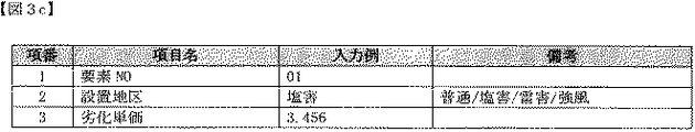
劣化要素管理機能170は、設備を劣化させる地区とその1日あたりの劣化単価を劣化要素データベースに登録する。図3cに、劣化要素データベースのデータ構成図を示す。劣化要素データベース130は、「要素NO」「設置地区」「劣化単価」を保持する。
The failure
The degradation
設備劣化度算出機能150は、設備情報データベース120と劣化要素データベース130を参照し、各設備の劣化度を算出する機能である。この算出した劣化度を使用して、設備情報データベース120の「劣化度」項目を更新する。
The equipment deterioration
リミット算出機能190は、故障履歴データベース110を参照し、種類やメーカー、タイプといった項目と劣化度項目の値を使用して、劣化度の平均値を算出し、それを設備の耐久度として、設備耐久度データベース140に登録する機能である。図3dに、設備耐久度データベースのデータ構成図を示す。設備耐久度データベースは、「耐久度NO」、「種類」、「メーカー」、「タイプ」、「型NO」、「年式」、「耐久度」を保持する。
The
劣化度設定機能200は、故障履歴データベース110を参照し、設置開始年月日および故障年月日の値から、設備が設置されていた期間を算出し、それぞれの設置地区に応じた期間から劣化単価を算出する。この算出式は、線形多項式となるため、各式より算出した劣化単価については、平均をとることで、より精緻化をはかることができる。
The degradation
保守点検優先度表示機能210は、設備劣化度算出機能180にて設定された劣化度、リミット算出機能190による各設備の耐久度である設備耐久度データベース140内のデータを入力とし、設備情報データベース120を参照し、各設備について耐久度を超過しているか否かの判定、および次回の保守点検日に耐久度を超過するか否かの判定を行う。また、劣化度について降順に並べ優先度を順に付与する。保守、点検時は、この保守点検優先度表示機能による表示結果をもとに対象設備を決定することができる。
The maintenance inspection
設備管理システムは、所謂コンピュータであり、処理装置(CPU)と、記憶装置(メモリ、ハードディスクドライブ)、外部のネットワークと通信可能な通信装置と、これらを接続するバスまたは内部ネットワークを備える。設備管理システムは、入力装置や表示装置を備えるのが好ましい。故障履歴データベース110、設備情報データベース120、劣化要素データベース130、設備耐久度データベース140は、記憶装置(主にハードディスクドライブ)上に構築(記憶)される。設備情報管理機能150、故障履歴管理機能160、劣化要素管理機能170、設備劣化度算出機能180、リミット算出機能190、劣化度設定機能200、保守点検優先度表示機能210は、処理装置が、記憶装置(主にメモリ)上に展開(記憶)されたプログラムに従って、動作(例えば、記憶装置(主にメモリ)上でデータを処理)することによって実現される。
The equipment management system is a so-called computer, and includes a processing device (CPU), a storage device (memory, hard disk drive), a communication device capable of communicating with an external network, and a bus or an internal network connecting them. The facility management system preferably includes an input device and a display device. The
次に、各機能を使用した処理の流れを図2に従って説明する。図2では、使用者と設備管理システムと簡略化しているが、この使用者からの入力という処理は、配電システムといったシステムからのデータ連けいによる入力処理でもかまわない。
まず、図2aは、設備故障時の処理フローを示す。システムの使用者は、故障した設備情報を設備管理システムに入力する(ステップ301)。設備情報とは、「設備NO」、「種類」、「メーカー」、「タイプ」、「型NO」、「年式」、「設置開始年月日」、「故障年月日」、「設置地区1」、「設置開始年月日1」、「設置終了年月日1」、「設置地区2」、「設置開始年月日2」、「設置終了年月日2」、「設置地区3」、「設置開始年月日3」、「設置終了年月日3」、・・・、「劣化度」をいう。設備管理システムでは、故障履歴管理機能160にて、入力された情報を故障履歴データベース110に登録する(ステップ302)。故障履歴データベース110に登録したため、設備情報管理機能150にて、故障した設備情報を設備情報データベース120から削除する(ステップ303)。最後に、劣化度設定機能200を使用して、故障した設備の設置地区、設置期間、設置開始年月日、故障年月日をもとに、既存の故障履歴データベース110の設備の情報を使用して、各劣化要素(例えば、普通、塩害、雷害、強風)の劣化単価(単位期間あたりの劣化度)を算出する。これは、各設備ごとに、劣化単価を変数とした連立線形多項式となる。具体的には以下のようになる。まず、各劣化要素の基準となる普通地区の劣化単価を1として、普通地区に設置されている設備の劣化度を算出する。具体的には、設備1が普通地区にT1期間、設備2が普通地区にT2期間設置されて故障した場合、
設備1の劣化度:T1×1=T1
設備2の劣化度:T2×1=T2
となる。劣化度は設置期間に比例する。ここで、設備3が設備1と同種の設備であった場合で、設備3は、塩害地区にT3期間設置されて故障した場合、塩害地区による劣化単価をXとすると、
設備3の劣化度:T3×X=T1
となり、X=T1/T3により塩害による劣化単価を求めることができる。通常、塩害地区の故障までの設置期間は、普通地区の故障までの設置期間よりも短いため、Xは1よりも大きい値となる。同種というのは、設備の種類、メーカー、タイプ、型NO、年式が同一の事を指す。このように、普通地区におかれていた設備を基準とし、各地区の劣化単価を求める。比較しやすいように、普通地区の故障した設備情報を、予め定めておくのが好ましい。
Next, the flow of processing using each function will be described with reference to FIG. In FIG. 2, the user and the equipment management system are simplified, but the input process from the user may be an input process based on data connection from a system such as a power distribution system.
First, FIG. 2a shows a processing flow at the time of equipment failure. The user of the system inputs the failed facility information into the facility management system (step 301). Equipment information includes "equipment NO", "type", "manufacturer", "type", "type NO", "year", "date of installation", "failure date", "installation area" 1 ”,“ Installation start date 1 ”,“ Installation end date 1 ”,“
Degradation of equipment 1: T1 x 1 = T1
Degradation of equipment 2: T2 x 1 = T2
It becomes. The degree of deterioration is proportional to the installation period. Here, when the
Degradation of equipment 3: T3 x X = T1
Thus, the unit cost of deterioration due to salt damage can be obtained by X = T1 / T3. Usually, since the installation period until the failure in the salt damage area is shorter than the installation period until the failure in the normal area, X is a value larger than 1. The same type means that the equipment type, manufacturer, type, type NO, and year are the same. In this way, the deterioration unit price of each district is obtained based on the equipment that was in the ordinary district. In order to make comparison easier, it is preferable to predetermine the facility information in the normal area that has failed.
また、設備4が設備1と同種の設備であった場合で、設備4は、塩害地区にT41期間、雷害地区にT42期間設置されて故障した場合、塩害地区による劣化単価をX、雷害地区による劣化単価をYとすると、
設備4の劣化度:T41×X+T42×Y=T1
となる。塩害地区の劣化単価X=T1/T3であるから、雷害地区による
劣化単価Y=T3(T1-T41)/(T3×T42)と求めることができる。このようにして劣化単価を求めて行くわけであるが、故障した設備が増加すると、劣化単価が一意に定まらない。この場合は、それぞれの劣化単価ごとに平均をとることで、より精度の高い劣化単価を設定していく。たとえば、設備5が設備1と同種の設備であった場合で、設備5は、普通地区にT51期間、雷害地区にT52期間設置されて故障した場合、雷害地区による劣化単価をYとすると、
設備4の劣化度:T51×1+T52×Y=T1
となる。したがって、雷害地区による劣化単価Y=(T1-T51)/T52となり、先ほど設
備4のときに求めた雷害地区による劣化単価Yの値と異なる場合がある。この場合
は、設備4で求めた劣化単価と設備5で求めた劣化単価の平均をとり、より精度の高
い値にするのである。この平均後の値を、各劣化要素の劣化単価とし、劣化要素データベース130の劣化単価を更新する。また、算出した劣化単価を使用して各設備がそれぞれの設置地区に設置されていた期間をかけることで、各設備の劣化度を計算し、故障履歴データベース110の劣化度項目を更新する(ステップ304)。
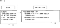
次に、図2bは、設備新規設置時および取り外しまたは、再設置時の処理フローを示す。使用者は、まず、設備情報を入力する(ステップ401)。ここでいう設備情報とは、新規に設置した設備であったり、取り外した設備、または点検後再設置した設備情報である。設備管理システムでは、設備情報管理機能150にて、設備NOを検索キーとして検索し、ヒットしなければ、新規の設備と判断して、設備情報データベース120に追加し、ヒットした場合、取り外しまたは再設置と判断し、該当設備NOのレコードを更新する(ステップ402)。
次に、図2cは、劣化要素の追加、更新時の処理フローを示す。これは、基本的な劣化要素である、塩害、雷害、強風以外の新規に劣化要素となる地区や事象が発生した場合である。使用者は、新しい劣化要素を入力する(ステップ501)。設備管理システムは、劣化要素管理機能170にて、劣化要素データベース130に入力された項目を追加する(ステップ502)。劣化単価については、初期値1(普通地区の劣化単価と同一の劣化単価)を設定する。これは、その劣化要素地区に設置され、故障設備が発生するたびに値が設定され、精緻化されていく。
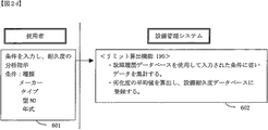
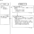
次に、図2dは、設備耐久度分析時の処理フローを示す。使用者は、設備の種類、メーカー、タイプ、型NO、年式といった分析したい条件を入力する(ステップ601)。設備管理システム100では、リミット算出機能190にて、故障履歴データベース110を使用して、入力された条件に従い、劣化度を集計する。具体的には、入力された条件をキー項目として、故障履歴データベース110を検索し、合致した1または複数の設備の劣化度項目の値を読み出し、読み出した劣化度について平均値を算出する。劣化度が最小値であった設備は、その入力条件のなかで、最も劣化度が小さかったにもかかわらず故障した設備であり、劣化度が最大値であった設備は、その入力条件のなかで、最も劣化度が大きかった設備である。これは、与えらた条件に合致する設備であっても、個体ごとに故障したときの劣化度が異なるためである。そのため保守点検計画に役立てるためには、このような個体ごとのばらつきを考慮し、与えらた条件に合致する設備の劣化度の平均値をとり、これを耐久度として扱う。平均の代わりに、標準偏差を用いてもよい。設備の劣化度がこの耐久度と同値になると、故障すると想定されるということを意味する。(ステップ602)
最後に、図2eは、保守点検作業計画時の処理フローを示す。使用者は、保守点検作業年月日、および次回作業年月日を入力する(ステップ701)。設備管理システムでは、設備劣化度算出機能180にて、設備情報データベース120を参照し、各設備について、作業年月日時点での劣化度、次回作業予定日での劣化度を算出する(ステップ702)。これは、各設備が、その設備劣化度算出機能180を使用した時点で設置されている設置地区にそのまま設置されていると仮定して、劣化度を計算する。例えば、次回作業予定日までの残り期間に劣化単価を乗算することによって計算することができる。その後、保守点検優先度表示機能210にて、故障履歴データベース110を参照し、設備劣化度算出機能180の算出結果である劣化度が、保守点検作業年月日で設備の耐久度を超えている設備、次回作業年月日で、同じ場所で使用し続けた場合、設備の耐久度を超えると想定される設備を出力する。これは、設備情報データベース120を検索し、各設備の現在設置されている設置地区を判定し、その設置地区の劣化単価と、次回作業年月日と保守点検作業年月日の間隔から次回作業年月日までの期間を算出し、それらをかけることで、次回作業年月日までに増加する劣化度を算出する。この増加する劣化度と保守点検作業年月日時の劣化度を足すことで次回作業年月日の劣化度を想定する。加えて、これら以外の設備について劣化度の降順でソートし出力する(ステップ703)。使用者は、この出力結果をもとに劣化度が耐久度を超えると予想された設備のみを保守、点検すべき設備として選定する。
In addition, when
Degradation of equipment 4: T41 × X + T42 × Y = T1
It becomes. Since the deterioration unit price X = T1 / T3 in the salt damage area, it can be determined that the deterioration unit price Y = T3 (T1-T41) / (T3 × T42) in the lightning damage area. In this way, the deterioration unit price is obtained. However, when the number of failed facilities increases, the deterioration unit price cannot be uniquely determined. In this case, a more accurate deterioration unit price is set by taking an average for each deterioration unit price. For example, if the
Degradation of equipment 4: T51 x 1 + T52 x Y = T1
It becomes. Therefore, the deterioration unit price Y due to lightning damage is Y = (T1-T51) / T52, which may be different from the value of the deterioration unit price Y due to lightning damage previously obtained for the
Next, FIG. 2b shows a processing flow at the time of new installation and removal or re-installation of equipment. The user first inputs equipment information (step 401). The equipment information here is equipment that has been newly installed, equipment that has been removed, or equipment that has been reinstalled after inspection. In the equipment management system, the equipment
Next, FIG. 2c shows a processing flow at the time of adding and updating deterioration elements. This is the case when a new area or event that becomes a deterioration factor other than the basic deterioration factors, such as salt damage, lightning damage, and strong wind, occurs. The user inputs a new deterioration factor (step 501). The facility management system adds items input to the
Next, FIG. 2d shows a processing flow at the time of equipment durability analysis. The user inputs conditions to be analyzed such as the type of equipment, manufacturer, type, type NO, and year (step 601). In the
Finally, FIG. 2e shows a processing flow at the time of maintenance inspection work planning. The user inputs the maintenance inspection work date and the next work date (step 701). In the equipment management system, the equipment deterioration
ただし、劣化度が耐久度を超えると予想された設備を基準に設備点検地区を選定し、その設備点検地区内で劣化度が耐久度を越えないが耐久度に近い(例えば、耐久度の80%を越えた場合の)設備も併せて保守、点検すべき設備として選定してもよい。これにより、より効率的に保守、点検を行うことができる。 However, an equipment inspection area is selected based on equipment that is expected to have a degree of deterioration exceeding the durability, and the deterioration degree does not exceed the durability within the equipment inspection area, but is close to the durability (for example, 80% of durability). You may also select equipment that should be maintained and inspected. Thereby, maintenance and inspection can be performed more efficiently.
尚、本発明は、配電設備に限らず、複数の場所で使いまわされる設備(機器)に適用可能である。 In addition, this invention is applicable not only to a power distribution installation but the installation (apparatus) reused in several places.
本発明は、配電設備を保守・点検するためのシステムに適用可能である。 The present invention is applicable to a system for maintaining / inspecting power distribution equipment.
100‥設備管理システム、110‥故障履歴データベース、120‥設備情報データベース、130‥劣化要素データベース、140‥設備耐久度データベース、150‥設備情報管理機能、160‥故障履歴管理機能、170‥劣化要素管理機能、180‥設備劣化度算出機能、190‥リミット算出機能、200‥劣化度設定機能、210‥保守点検優先度表示機能
DESCRIPTION OF
Claims (6)
設備に対する作業時点での劣化度が耐久度を越える設備または設備を同じ設置場所で使用しつづけた場合に設備に対する次回の作業時点での劣化度が前記耐久度を越える設備の少なくとも1つを、優先的に保守、点検すべき設備として出力する手段とを備えることを特徴とする設備のライフサイクルマネジメントシステム。 Means for calculating the degree of deterioration of each facility from the installation location of each facility and the installation period at each location;
When the equipment or equipment whose degree of deterioration at the time of work on the equipment exceeds the durability or the equipment is continuously used at the same installation location, at least one of the equipment whose degree of deterioration at the time of the next work on the equipment exceeds the above-mentioned durability, A facility life cycle management system comprising a means for outputting as a facility to be preferentially maintained and inspected.
前記劣化度を算出する手段は、基準となる設置場所の故障までの期間と対象となる設置地区の故障までの期間とに基づいて、前記基準となる設置場所に対する前記対象となる設置地区の単位期間あたりの劣化度を算出し、前記単位期間あたりの劣化度に前記設置期間を乗算することにより、前記劣化度を算出することを特徴とする設備のライフサイクルマネジメントシステム。 In the life cycle management system according to claim 1,
The means for calculating the degree of deterioration is a unit of the target installation area with respect to the reference installation location based on a period until failure of the reference installation location and a period until failure of the target installation district. A facility life cycle management system, wherein a deterioration degree per period is calculated, and the deterioration degree is calculated by multiplying the deterioration degree per unit period by the installation period.
複数の設備の劣化度の平均値から前記耐久度を算出する手段を備えることを特徴とする設備のライフサイクルマネジメントシステム。 In the life cycle management system according to claim 1 or 2,
A facility life cycle management system comprising means for calculating the durability from an average value of deterioration degrees of a plurality of facilities.
設備に対する作業時点での劣化度が耐久度を越える設備または設備を同じ設置場所で使用しつづけた場合に設備に対する次回の作業時点での劣化度が前記耐久度を越える設備の少なくとも1つを、優先的に保守、点検すべき設備として出力することを特徴とする設備のライフサイクルマネジメント方法。 Calculate the degree of deterioration of each facility from the installation location of each facility and the installation period at each location.
When the equipment or equipment whose degree of deterioration at the time of work on the equipment exceeds the durability or the equipment is continuously used at the same installation location, at least one of the equipment whose degree of deterioration at the time of the next work on the equipment exceeds the above-mentioned durability, A life cycle management method for equipment, characterized in that it is output as equipment to be preferentially maintained and inspected.
前記記憶装置は、各設備の設置場所および各設置場所での設置期間を記憶し、
前記処理装置は、前記記憶装置から前記各設備の設置場所および各設置場所での設置期間を読み出し、前記各設備の設置場所および各設置場所での設置期間から各設備の劣化度を算出し、各設備について、前記設備に対する作業時点での劣化度が前記耐久度を越えるか否かまたはまたは設備を同じ設置場所で使用しつづけた場合に前記設備に対する次回の作業時点での劣化度が前記耐久度を越えるか否かの少なくとも1つを判定し、前記設備に対する作業時点での劣化度が前記耐久度を越える設備または前記設備を同じ設置場所で使用しつづけた場合に前記設備に対する次回の作業時点での劣化度が前記耐久度を越える設備の少なくとも1つを出力することを特徴とする設備のライフサイクルマネジメントシステム。 A processing device and a storage device;
The storage device stores the installation location of each facility and the installation period at each installation location,
The processing device reads the installation location of each facility and the installation period at each installation location from the storage device, calculates the degree of deterioration of each facility from the installation location of each facility and the installation period at each installation location, For each facility, whether or not the degree of deterioration at the time of work on the equipment exceeds the durability, or when the equipment continues to be used at the same installation location, the degree of deterioration at the time of the next work on the equipment is the durability. If at least one of whether or not it exceeds the degree of deterioration and the degree of deterioration at the time of work on the equipment exceeds the durability, or if the equipment continues to be used at the same installation location, the next work on the equipment A facility life cycle management system that outputs at least one of the facilities whose degree of deterioration at the time exceeds the durability.
前記記憶装置が、各設備の設置場所および各設置場所での設置期間を記憶しており、
前記処理装置が、前記記憶装置から前記各設備の設置場所および各設置場所での設置期間を読み出し、前記各設備の設置場所および各設置場所での設置期間から各設備の劣化度を算出し、
前記処理装置が、各設備について、前記設備に対する作業時点での劣化度が前記耐久度を越えるか否かまたはまたは設備を同じ設置場所で使用しつづけた場合に前記設備に対する次回の作業時点での劣化度が前記耐久度を越えるか否かの少なくとも1つを判定し、
前記処理装置が、前記設備に対する作業時点での劣化度が前記耐久度を越える設備または前記設備を同じ設置場所で使用しつづけた場合に前記設備に対する次回の作業時点での劣化度が前記耐久度を越える設備の少なくとも1つを出力することを特徴とする設備のライフサイクルマネジメント方法。 In a life cycle management method for equipment executed on a computer having a processing device and a storage device,
The storage device stores the installation location of each facility and the installation period at each installation location,
The processing device reads the installation location of each facility and the installation period at each installation location from the storage device, calculates the deterioration degree of each facility from the installation location of each facility and the installation period at each installation location,
For each facility, the processing device determines whether the degradation level at the time of work on the facility exceeds the durability, or if the facility continues to be used at the same installation location, Determining at least one of whether the degree of deterioration exceeds the durability,
When the processing device continues to use the equipment having the degree of deterioration at the time of work on the equipment exceeding the durability or the equipment at the same installation location, the degree of deterioration at the time of the next work on the equipment is the degree of durability. A life cycle management method for equipment, characterized in that at least one of the equipment exceeding the above is output.
Priority Applications (1)
| Application Number | Priority Date | Filing Date | Title |
|---|---|---|---|
| JP2008180887A JP2010020573A (en) | 2008-07-11 | 2008-07-11 | System for managing life cycle of equipment and method therefor |
Applications Claiming Priority (1)
| Application Number | Priority Date | Filing Date | Title |
|---|---|---|---|
| JP2008180887A JP2010020573A (en) | 2008-07-11 | 2008-07-11 | System for managing life cycle of equipment and method therefor |
Publications (1)
| Publication Number | Publication Date |
|---|---|
| JP2010020573A true JP2010020573A (en) | 2010-01-28 |
Family
ID=41705394
Family Applications (1)
| Application Number | Title | Priority Date | Filing Date |
|---|---|---|---|
| JP2008180887A Pending JP2010020573A (en) | 2008-07-11 | 2008-07-11 | System for managing life cycle of equipment and method therefor |
Country Status (1)
| Country | Link |
|---|---|
| JP (1) | JP2010020573A (en) |
Cited By (4)
| Publication number | Priority date | Publication date | Assignee | Title |
|---|---|---|---|---|
| JP2013025346A (en) * | 2011-07-15 | 2013-02-04 | Hitachi Ltd | Management system and management method |
| JP2015087881A (en) * | 2013-10-29 | 2015-05-07 | 京セラ株式会社 | Equipment management system, equipment management device and equipment management method |
| WO2016088180A1 (en) * | 2014-12-01 | 2016-06-09 | 東京電力ホールディングス株式会社 | Facility maintenance and management method |
| WO2020008490A1 (en) * | 2018-07-02 | 2020-01-09 | 株式会社東芝 | Electric power equipment planning assistance system |
Citations (4)
| Publication number | Priority date | Publication date | Assignee | Title |
|---|---|---|---|---|
| JPH11141352A (en) * | 1997-11-07 | 1999-05-25 | Hitachi Ltd | Maintenance managing device and method for gas turbine high temperature components |
| JP2000124094A (en) * | 1998-10-20 | 2000-04-28 | Dainippon Screen Mfg Co Ltd | Substrate-treating apparatus and method for predicting failures thereof |
| JP2006149873A (en) * | 2004-11-30 | 2006-06-15 | Toshiba Corp | Medical device control apparatus, method, and program |
| JP2007316826A (en) * | 2006-05-24 | 2007-12-06 | Chugoku Electric Power Co Inc:The | Article deterioration diagnostic system and article degradation diagnostic method |
-
2008
- 2008-07-11 JP JP2008180887A patent/JP2010020573A/en active Pending
Patent Citations (4)
| Publication number | Priority date | Publication date | Assignee | Title |
|---|---|---|---|---|
| JPH11141352A (en) * | 1997-11-07 | 1999-05-25 | Hitachi Ltd | Maintenance managing device and method for gas turbine high temperature components |
| JP2000124094A (en) * | 1998-10-20 | 2000-04-28 | Dainippon Screen Mfg Co Ltd | Substrate-treating apparatus and method for predicting failures thereof |
| JP2006149873A (en) * | 2004-11-30 | 2006-06-15 | Toshiba Corp | Medical device control apparatus, method, and program |
| JP2007316826A (en) * | 2006-05-24 | 2007-12-06 | Chugoku Electric Power Co Inc:The | Article deterioration diagnostic system and article degradation diagnostic method |
Cited By (5)
| Publication number | Priority date | Publication date | Assignee | Title |
|---|---|---|---|---|
| JP2013025346A (en) * | 2011-07-15 | 2013-02-04 | Hitachi Ltd | Management system and management method |
| JP2015087881A (en) * | 2013-10-29 | 2015-05-07 | 京セラ株式会社 | Equipment management system, equipment management device and equipment management method |
| WO2016088180A1 (en) * | 2014-12-01 | 2016-06-09 | 東京電力ホールディングス株式会社 | Facility maintenance and management method |
| JPWO2016088180A1 (en) * | 2014-12-01 | 2017-04-27 | 東京電力ホールディングス株式会社 | Equipment maintenance management method |
| WO2020008490A1 (en) * | 2018-07-02 | 2020-01-09 | 株式会社東芝 | Electric power equipment planning assistance system |
Similar Documents
| Publication | Publication Date | Title |
|---|---|---|
| CN108510221B (en) | Inventory management system having functions of inventory management and preventive maintenance | |
| CN104966141B (en) | Method and system for updating a model used to generate an industrial asset health profile | |
| JP5844978B2 (en) | System and method for monitoring a gas turbine | |
| JP6865189B2 (en) | Failure probability evaluation system and method | |
| US9514577B2 (en) | Integrating economic considerations to develop a component replacement policy based on a cumulative wear-based indicator for a vehicular component | |
| JP5463885B2 (en) | Batch job processing time estimation program, method and apparatus | |
| JP6143994B2 (en) | Remote monitoring device, remote monitoring maintenance system, remote monitoring method, and remote monitoring program | |
| JP2005182465A (en) | Maintenance support method and program | |
| WO2018105104A1 (en) | Failure risk index estimation device and failure risk index estimation method | |
| Zheng et al. | Optimal maintenance policy for a system with preventive repair and two types of failures | |
| JP6359960B2 (en) | Failure prediction apparatus, failure prediction method, and failure prediction program | |
| CN104919380A (en) | Profiling transformer of power system | |
| JP2016095751A (en) | Abnormality unit identification program, abnormality unit identification method and abnormality unit identification system | |
| US11796992B2 (en) | Condition-based method for malfunction prediction | |
| JP4078671B2 (en) | Plant maintenance management method | |
| JP5752621B2 (en) | Demand forecasting device, demand forecasting program, and demand forecasting method | |
| JP2010020573A (en) | System for managing life cycle of equipment and method therefor | |
| Cao et al. | Optimization of condition-based maintenance for multi-state deterioration systems under random shock | |
| EP3663874A1 (en) | Method and system for optimizing a manufacturing process based on a surrogate model of a part | |
| CN115689207A (en) | Wind power plant operation and maintenance management method and device, computer equipment and storage medium | |
| JP5864847B2 (en) | Maintenance management system and maintenance management method | |
| CN113887990A (en) | Electrical equipment maintenance decision optimization method | |
| Grobbelaar et al. | Determining the cost of predictive component replacement in order to assist with maintenance decision-making | |
| CN113177653A (en) | System and method for predictive analytics of assets | |
| CN113221324A (en) | Life cycle prediction method and life cycle prediction system for parking lot equipment |
Legal Events
| Date | Code | Title | Description |
|---|---|---|---|
| A621 | Written request for application examination |
Free format text: JAPANESE INTERMEDIATE CODE: A621 Effective date: 20110118 |
|
| A977 | Report on retrieval |
Free format text: JAPANESE INTERMEDIATE CODE: A971007 Effective date: 20120614 |
|
| A131 | Notification of reasons for refusal |
Free format text: JAPANESE INTERMEDIATE CODE: A131 Effective date: 20120703 |
|
| A02 | Decision of refusal |
Free format text: JAPANESE INTERMEDIATE CODE: A02 Effective date: 20121106 |