JP2010019829A - Pressure sensor - Google Patents
Pressure sensor Download PDFInfo
- Publication number
- JP2010019829A JP2010019829A JP2009027765A JP2009027765A JP2010019829A JP 2010019829 A JP2010019829 A JP 2010019829A JP 2009027765 A JP2009027765 A JP 2009027765A JP 2009027765 A JP2009027765 A JP 2009027765A JP 2010019829 A JP2010019829 A JP 2010019829A
- Authority
- JP
- Japan
- Prior art keywords
- pressure
- housing
- diaphragm
- sensitive element
- pressure sensor
- Prior art date
- Legal status (The legal status is an assumption and is not a legal conclusion. Google has not performed a legal analysis and makes no representation as to the accuracy of the status listed.)
- Withdrawn
Links
- 238000001514 detection method Methods 0.000 claims abstract description 70
- 239000000853 adhesive Substances 0.000 claims abstract description 61
- 230000001070 adhesive effect Effects 0.000 claims abstract description 61
- 230000005540 biological transmission Effects 0.000 claims abstract description 54
- 238000006073 displacement reaction Methods 0.000 claims abstract description 5
- TWNQGVIAIRXVLR-UHFFFAOYSA-N oxo(oxoalumanyloxy)alumane Chemical compound O=[Al]O[Al]=O TWNQGVIAIRXVLR-UHFFFAOYSA-N 0.000 claims description 10
- 150000001875 compounds Chemical class 0.000 claims description 5
- 238000007789 sealing Methods 0.000 claims 2
- 230000035945 sensitivity Effects 0.000 abstract description 13
- 239000012790 adhesive layer Substances 0.000 description 48
- 239000003921 oil Substances 0.000 description 28
- 239000007788 liquid Substances 0.000 description 25
- VYPSYNLAJGMNEJ-UHFFFAOYSA-N silicon dioxide Inorganic materials O=[Si]=O VYPSYNLAJGMNEJ-UHFFFAOYSA-N 0.000 description 12
- NJPPVKZQTLUDBO-UHFFFAOYSA-N novaluron Chemical compound C1=C(Cl)C(OC(F)(F)C(OC(F)(F)F)F)=CC=C1NC(=O)NC(=O)C1=C(F)C=CC=C1F NJPPVKZQTLUDBO-UHFFFAOYSA-N 0.000 description 11
- 230000006835 compression Effects 0.000 description 9
- 238000007906 compression Methods 0.000 description 9
- 230000008859 change Effects 0.000 description 8
- 238000000034 method Methods 0.000 description 8
- 241000405147 Hermes Species 0.000 description 7
- 239000000463 material Substances 0.000 description 7
- 235000012239 silicon dioxide Nutrition 0.000 description 7
- 239000000919 ceramic Substances 0.000 description 6
- 229910052751 metal Inorganic materials 0.000 description 5
- 239000002184 metal Substances 0.000 description 5
- 239000010453 quartz Substances 0.000 description 5
- 239000011324 bead Substances 0.000 description 4
- 230000002093 peripheral effect Effects 0.000 description 4
- 230000003014 reinforcing effect Effects 0.000 description 4
- 239000000758 substrate Substances 0.000 description 4
- BPQQTUXANYXVAA-UHFFFAOYSA-N Orthosilicate Chemical compound [O-][Si]([O-])([O-])[O-] BPQQTUXANYXVAA-UHFFFAOYSA-N 0.000 description 3
- 239000013078 crystal Substances 0.000 description 3
- 238000010586 diagram Methods 0.000 description 3
- 230000008569 process Effects 0.000 description 3
- 229920005989 resin Polymers 0.000 description 3
- 239000011347 resin Substances 0.000 description 3
- 239000000377 silicon dioxide Substances 0.000 description 3
- XLYOFNOQVPJJNP-UHFFFAOYSA-N water Substances O XLYOFNOQVPJJNP-UHFFFAOYSA-N 0.000 description 3
- 239000004593 Epoxy Substances 0.000 description 2
- PXHVJJICTQNCMI-UHFFFAOYSA-N Nickel Chemical compound [Ni] PXHVJJICTQNCMI-UHFFFAOYSA-N 0.000 description 2
- 239000004115 Sodium Silicate Substances 0.000 description 2
- MCMNRKCIXSYSNV-UHFFFAOYSA-N Zirconium dioxide Chemical compound O=[Zr]=O MCMNRKCIXSYSNV-UHFFFAOYSA-N 0.000 description 2
- 230000009471 action Effects 0.000 description 2
- PNEYBMLMFCGWSK-UHFFFAOYSA-N aluminium oxide Inorganic materials [O-2].[O-2].[O-2].[Al+3].[Al+3] PNEYBMLMFCGWSK-UHFFFAOYSA-N 0.000 description 2
- ILRRQNADMUWWFW-UHFFFAOYSA-K aluminium phosphate Chemical compound O1[Al]2OP1(=O)O2 ILRRQNADMUWWFW-UHFFFAOYSA-K 0.000 description 2
- 238000009530 blood pressure measurement Methods 0.000 description 2
- 230000000694 effects Effects 0.000 description 2
- 229920006332 epoxy adhesive Polymers 0.000 description 2
- 238000007689 inspection Methods 0.000 description 2
- 238000009434 installation Methods 0.000 description 2
- 238000004519 manufacturing process Methods 0.000 description 2
- 230000010355 oscillation Effects 0.000 description 2
- 229920001296 polysiloxane Polymers 0.000 description 2
- 238000003825 pressing Methods 0.000 description 2
- 230000002787 reinforcement Effects 0.000 description 2
- 238000010008 shearing Methods 0.000 description 2
- NTHWMYGWWRZVTN-UHFFFAOYSA-N sodium silicate Chemical compound [Na+].[Na+].[O-][Si]([O-])=O NTHWMYGWWRZVTN-UHFFFAOYSA-N 0.000 description 2
- 229910052911 sodium silicate Inorganic materials 0.000 description 2
- 229910001220 stainless steel Inorganic materials 0.000 description 2
- 239000010935 stainless steel Substances 0.000 description 2
- WSMQKESQZFQMFW-UHFFFAOYSA-N 5-methyl-pyrazole-3-carboxylic acid Chemical compound CC1=CC(C(O)=O)=NN1 WSMQKESQZFQMFW-UHFFFAOYSA-N 0.000 description 1
- NIXOWILDQLNWCW-UHFFFAOYSA-N Acrylic acid Chemical compound OC(=O)C=C NIXOWILDQLNWCW-UHFFFAOYSA-N 0.000 description 1
- 239000004111 Potassium silicate Substances 0.000 description 1
- 229910052782 aluminium Inorganic materials 0.000 description 1
- XAGFODPZIPBFFR-UHFFFAOYSA-N aluminium Chemical compound [Al] XAGFODPZIPBFFR-UHFFFAOYSA-N 0.000 description 1
- 238000005452 bending Methods 0.000 description 1
- 230000008901 benefit Effects 0.000 description 1
- 230000007797 corrosion Effects 0.000 description 1
- 238000005260 corrosion Methods 0.000 description 1
- 230000008878 coupling Effects 0.000 description 1
- 238000010168 coupling process Methods 0.000 description 1
- 238000005859 coupling reaction Methods 0.000 description 1
- 239000002178 crystalline material Substances 0.000 description 1
- 230000006866 deterioration Effects 0.000 description 1
- 238000005516 engineering process Methods 0.000 description 1
- 238000005530 etching Methods 0.000 description 1
- 238000002474 experimental method Methods 0.000 description 1
- 239000001023 inorganic pigment Substances 0.000 description 1
- 238000005304 joining Methods 0.000 description 1
- 239000010410 layer Substances 0.000 description 1
- GQYHUHYESMUTHG-UHFFFAOYSA-N lithium niobate Chemical compound [Li+].[O-][Nb](=O)=O GQYHUHYESMUTHG-UHFFFAOYSA-N 0.000 description 1
- 230000007774 longterm Effects 0.000 description 1
- 239000000395 magnesium oxide Substances 0.000 description 1
- CPLXHLVBOLITMK-UHFFFAOYSA-N magnesium oxide Inorganic materials [Mg]=O CPLXHLVBOLITMK-UHFFFAOYSA-N 0.000 description 1
- AXZKOIWUVFPNLO-UHFFFAOYSA-N magnesium;oxygen(2-) Chemical compound [O-2].[Mg+2] AXZKOIWUVFPNLO-UHFFFAOYSA-N 0.000 description 1
- 238000005259 measurement Methods 0.000 description 1
- 230000007246 mechanism Effects 0.000 description 1
- 230000004048 modification Effects 0.000 description 1
- 238000012986 modification Methods 0.000 description 1
- 239000010705 motor oil Substances 0.000 description 1
- 229910052759 nickel Inorganic materials 0.000 description 1
- 150000002816 nickel compounds Chemical class 0.000 description 1
- 238000000206 photolithography Methods 0.000 description 1
- NNHHDJVEYQHLHG-UHFFFAOYSA-N potassium silicate Chemical compound [K+].[K+].[O-][Si]([O-])=O NNHHDJVEYQHLHG-UHFFFAOYSA-N 0.000 description 1
- 229910052913 potassium silicate Inorganic materials 0.000 description 1
- 235000019353 potassium silicate Nutrition 0.000 description 1
- 238000012545 processing Methods 0.000 description 1
- 239000004576 sand Substances 0.000 description 1
- 229910052710 silicon Inorganic materials 0.000 description 1
- 239000010703 silicon Substances 0.000 description 1
- 229920002545 silicone oil Polymers 0.000 description 1
- 238000004088 simulation Methods 0.000 description 1
- 235000019795 sodium metasilicate Nutrition 0.000 description 1
- 238000003860 storage Methods 0.000 description 1
- 239000000725 suspension Substances 0.000 description 1
- 238000013022 venting Methods 0.000 description 1
- 238000003466 welding Methods 0.000 description 1
- GFQYVLUOOAAOGM-UHFFFAOYSA-N zirconium(iv) silicate Chemical compound [Zr+4].[O-][Si]([O-])([O-])[O-] GFQYVLUOOAAOGM-UHFFFAOYSA-N 0.000 description 1
Images

Classifications
-
- G—PHYSICS
- G01—MEASURING; TESTING
- G01L—MEASURING FORCE, STRESS, TORQUE, WORK, MECHANICAL POWER, MECHANICAL EFFICIENCY, OR FLUID PRESSURE
- G01L9/00—Measuring steady of quasi-steady pressure of fluid or fluent solid material by electric or magnetic pressure-sensitive elements; Transmitting or indicating the displacement of mechanical pressure-sensitive elements, used to measure the steady or quasi-steady pressure of a fluid or fluent solid material, by electric or magnetic means
- G01L9/0001—Transmitting or indicating the displacement of elastically deformable gauges by electric, electro-mechanical, magnetic or electro-magnetic means
- G01L9/0008—Transmitting or indicating the displacement of elastically deformable gauges by electric, electro-mechanical, magnetic or electro-magnetic means using vibrations
- G01L9/0022—Transmitting or indicating the displacement of elastically deformable gauges by electric, electro-mechanical, magnetic or electro-magnetic means using vibrations of a piezoelectric element
Landscapes
- Physics & Mathematics (AREA)
- General Physics & Mathematics (AREA)
- Measuring Fluid Pressure (AREA)
Abstract
【課題】小型化が可能で感度の良い圧力センサーを提供する。
【解決手段】ハウジング12と、前記ハウジング12の口金22を封止し、一面が受圧面であるダイアフラム32と、前記ハウジング12の内部から前記ダイアフラム32の他面の中央部に接続した力伝達手段34と、力の検出方向を検出軸とする感圧素子38とを有し、前記力伝達手段34の変位方向及び前記検出軸の方向は前記受圧面に対してほぼ垂直であり、前記感圧素子38の一端は前記ハウジング12に、他端は前記力伝達手段34に、接着手段を介して支持固定され、前記接着手段が無機系接着剤40である。
【選択図】 図1A pressure sensor that can be miniaturized and has high sensitivity is provided.
SOLUTION: A housing 12, a base 22 of the housing 12, and a diaphragm 32 whose one surface is a pressure receiving surface, and a force transmitting means connected from the inside of the housing 12 to a central portion of the other surface of the diaphragm 32. 34 and a pressure sensitive element 38 having a detection direction of force as a detection axis, the displacement direction of the force transmission means 34 and the direction of the detection axis are substantially perpendicular to the pressure receiving surface, One end of the element 38 is supported and fixed to the housing 12 and the other end to the force transmission means 34 via an adhesive means, and the adhesive means is an inorganic adhesive 40.
[Selection] Figure 1
Description
本発明は、圧力センサーに関し、特に受圧媒体としてのオイルを使用しない圧力センサーであって、感圧素子の支持部に起因した圧力検出の誤差を減少させる技術に関する。 The present invention relates to a pressure sensor, and more particularly to a technique that does not use oil as a pressure-receiving medium and that reduces errors in pressure detection caused by a support portion of a pressure-sensitive element.
従来から、水圧計、気圧計、差圧計などとして圧電振動素子を感圧素子として使用した圧力センサーが知られている。前記圧電振動素子は、例えば、板状の圧電基板上に電極パターンが形成され、力の検出方向に検出軸を設定しており、前記検出軸の方向に圧力が加わると、前記圧電振動子の共振周波数が変化し、前記共振周波数の変化から圧力を検出する。特許文献1〜3には、感圧素子として圧電振動素子を用いた圧力センサーが開示されている。圧力導入口によりベローズに圧力が加わると前記ベローズの有効面積に応じた力がピボット(撓みヒンジ)を支点とした力伝達手段を介して圧電振動素子に圧縮或いは引張力として力Fが加わる。前記圧電振動子には、前記力Fに応じた応力が生じることになり、前記応力により共振周波数が変化する。前記圧力センサーは、圧電振動子に生じる共振周波数の変化を検出することにより圧力を測定するものである。 Conventionally, a pressure sensor using a piezoelectric vibration element as a pressure-sensitive element is known as a water pressure gauge, a barometer, a differential pressure gauge, or the like. In the piezoelectric vibration element, for example, an electrode pattern is formed on a plate-shaped piezoelectric substrate, and a detection axis is set in the force detection direction. When pressure is applied in the direction of the detection axis, The resonance frequency changes, and the pressure is detected from the change in the resonance frequency. Patent Documents 1 to 3 disclose a pressure sensor using a piezoelectric vibration element as a pressure sensitive element. When pressure is applied to the bellows through the pressure inlet, a force F corresponding to the effective area of the bellows is applied as a compression or tensile force to the piezoelectric vibration element via force transmission means with a pivot (flexible hinge) as a fulcrum. A stress corresponding to the force F is generated in the piezoelectric vibrator, and the resonance frequency changes due to the stress. The pressure sensor measures pressure by detecting a change in resonance frequency generated in the piezoelectric vibrator.
以下に、従来の圧力センサーを、特許文献1などに開示されている例を用いて説明する。図8は従来の圧力センサーの構造を示した模式図である。
図8(a)に示す従来の圧力センサー501は、対向して配置された第1及び第2の圧力入力口502、503を有する筐体504と、筐体504の内部に力伝達部材505とを備え、力伝達部材505の一端を挟むように第1のベローズ506、および第2のベローズ507を接続している。そして、第1のベローズ506の他端を第1の圧力入力口502に接続して測定対象圧力を導入するようにし、第2のベローズ507の他端を第2の圧力入力口503に接続して大気圧を導入するようにしている。さらに、力伝達部材505の他端と基板508のピボット(支点)ではない方の端部との間に、感圧素子として双音叉型振動子509を配置している。
Below, the conventional pressure sensor is demonstrated using the example currently disclosed by patent document 1. FIG. 8 is a schematic diagram showing the structure of a conventional pressure sensor.
A
ここで、圧力センサーにおいて、高精度に圧力を検出する場合、検出対象側のベローズの内部には、液体が充填されている。前記液体としては、ベローズの内部や内部の蛇腹部分に気泡が入り込んだり、溜まらないようにするため、一般的に粘性の高いシリコンオイルなどのオイルが用いられている。 Here, when the pressure sensor detects the pressure with high accuracy, the bellows on the detection target side is filled with liquid. As the liquid, in order to prevent bubbles from entering or collecting in the bellows or the bellows portion of the bellows, oil such as silicone oil having high viscosity is generally used.
このように、第1のベローズ506の内部には、粘性のあるオイル510が充填されており、圧力測定の対象が液体の場合には、第1の圧力入力口502に開けられた開口部511により液体とオイル510とが接触して相対する構造となっている。なお、開口部511はオイル510が外部に漏れないような開口径が設定されている。
As described above, the
このような構成の圧力センサー501においては、圧力測定の対象となる液体より圧力Fが第1のベローズ506の内部に充填されているオイル510に加わると、第1のベローズ506を経て圧力Fが、力伝達部材505の一端に加わる。一方、第2のベローズ507には、大気圧が加わっており、大気圧に相当する力が力伝達部材505の一端に加わっている。
In the
この結果、力伝達部材505の他端を介して、圧力測定の対象となる液体より加わった圧力Fと大気圧による圧力の差圧に相当する力が基板508のピボットを支点にして、双音叉型振動子509に圧縮力、或いは引張力として加わる。双音叉型振動子509に圧縮力、或いは引張力が加わると、双音叉型振動子509には応力が生じ、前記応力の大きさに応じて共振周波数が変化するので、その共振周波数を測定することにより、圧力Fの大きさを検出することができる。
As a result, the force corresponding to the pressure difference between the pressure F applied from the liquid whose pressure is to be measured via the other end of the
一方、特許文献4には、前述の圧力センサーで用いるようなピボット(撓みヒンジ)を支点とした揺動レバーを用いた高価な力伝達手段(カンチレバー)を用いない構造のものが提示されている。これは、センサハウジング内に一直線上に2つのベローズを配列して間に台座を挟み込み、それぞれのベローズに導入される圧力の差に起因する圧力変動を台座の挙動で検出しようとするものである。このため、第1のベローズの一端と第2のベローズの一端との間に振動子接着用台座を挟み込み、第2のベローズの外周側にて、前記台座と第2のベローズの他端側のハウジング壁面とに感圧素子の両端の各々を固定する。そして、第2のベローズを間に挟む線対称位置に補強板を配置し、当該補強板の両端の各々を前記台座と前記ハウジング壁面とに固定してなる構造を採用している。 On the other hand, Patent Document 4 proposes a structure that does not use expensive force transmission means (cantilever) using a swing lever with a pivot (flexible hinge) as a fulcrum as used in the pressure sensor described above. . This is an arrangement in which two bellows are arranged in a straight line in the sensor housing, a pedestal is sandwiched between them, and pressure fluctuation caused by the difference in pressure introduced to each bellows is detected by the behavior of the pedestal. . For this reason, the vibrator bonding pedestal is sandwiched between one end of the first bellows and one end of the second bellows, and on the outer peripheral side of the second bellows, on the other end side of the pedestal and the second bellows. Each of both ends of the pressure sensitive element is fixed to the housing wall surface. And the structure which arrange | positions a reinforcement board in the line symmetrical position which pinches | interposes a 2nd bellows, and fixes each of the both ends of the said reinforcement board to the said base and the said housing wall surface is employ | adopted.
更に、特許文献5においては、特許文献4に開示された前記圧力センサーに関し、ベローズの圧力検出軸方向と直交する方向からの衝撃に対する強度が弱いという課題を解決するために、圧力検出軸方向と直交する方向に前記台座とハウジングとを補強用弾性部材(いわゆるバネ)を用いて連結してなる圧力センサーが提案されている。 Further, in Patent Document 5, with respect to the pressure sensor disclosed in Patent Document 4, in order to solve the problem that the strength against impact from a direction orthogonal to the pressure detection axis direction of the bellows is weak, A pressure sensor has been proposed in which the pedestal and the housing are connected in a direction orthogonal to each other by using a reinforcing elastic member (so-called spring).
次に、特許文献6、7には、エンジン内部の油圧を検出するためにエンジンブロックに固定して使用する圧力センサーが開示されている。この圧力センサーは印加された圧力に応じた電気信号を出力するセンシング部、圧力を受圧する受圧用ダイアフラム部、ダイアフラムからセンシング部へ圧力を伝達するための圧力伝達部材とからなり、具体的には、中空金属ステムの一方の端面に受圧用の第1ダイアフラムを設け、他方の端面に検出用の第2ダイアフラムを設け、ステム内にて前記第1、第2ダイアフラム間に力伝達部材を介在させている。力伝達部材は金属あるいはセラミックからなるシャフトであり、これを一対のダイアフラム間にプレストレスを与えた状態で介在させるようにしている。そして、第2ダイアフラムの外端面に圧力検出素子としての歪ゲージ機能をもつチップを貼り付け、第1ダイアフラムで受けた圧力を力伝達部材で第2ダイアフラムに伝達し、第2ダイアフラムの変形を歪ゲージチップにより電気信号に変換することでエンジン油圧を検出するようにしている。 Next, Patent Documents 6 and 7 disclose pressure sensors that are used by being fixed to an engine block in order to detect the oil pressure inside the engine. This pressure sensor is composed of a sensing unit that outputs an electrical signal corresponding to an applied pressure, a pressure receiving diaphragm unit that receives pressure, and a pressure transmission member that transmits pressure from the diaphragm to the sensing unit. A first diaphragm for pressure reception is provided on one end face of the hollow metal stem, a second diaphragm for detection is provided on the other end face, and a force transmission member is interposed between the first and second diaphragms in the stem. ing. The force transmission member is a shaft made of metal or ceramic, and is interposed between the pair of diaphragms with a prestress applied. Then, a chip having a strain gauge function as a pressure detecting element is attached to the outer end surface of the second diaphragm, and the pressure received by the first diaphragm is transmitted to the second diaphragm by the force transmission member, and the deformation of the second diaphragm is distorted. The engine oil pressure is detected by converting it into an electrical signal using a gauge chip.
しかしながら、特許文献1〜3の発明においては、図8に示す如き圧力センサー501のように、第1のベローズ506に充填されているオイル510は圧力センサー501を構成する要素、例えば、力伝達部材505や双音叉型振動子509などに比べて熱膨張係数が大きいので、圧力センサー501を構成する各部材に温度変化による熱歪みが生じることとなる。このような熱歪みが不要な応力として双音叉型振動子509に作用するので、測定した圧力値に誤差が生じることとなり圧力センサーの特性を悪化させるという問題があった。
However, in the inventions of Patent Documents 1 to 3, like the
また、第1のベローズ506に充填されているオイル510は、圧力測定の対象となる液体と接触して相対しているが、圧力センサーの設置方法によりオイル510が圧力測定に対象となる液体側に流出したり、液体が第1のベローズ506側に流入することもあるので、第1のベローズ506に充填されているオイル510内に気泡が発生する場合がある。オイル510内に気泡が発生すると、圧力の伝達媒体として機能しているオイル510は、力伝達部材505を経由して双音叉型振動子に安定して力を伝達することができないので、圧力測定に誤差を生ずる可能性がある。
In addition, the
さらに、上述したように、オイル510は、圧力測定の対象となる液体と接触して相対しているため、圧力センサーの設置方法によりオイル510が圧力測定の対象となる液体側に流出する可能性があり、異物の混入を嫌う清浄な液体の圧力測定を行う場合の用途には、オイル510を使用した従来の如き圧力センサーを使用することができないという問題があった。
Further, as described above, since the
さらにまた、従来の如き圧力センサー501は、力伝達部材505が、複雑な構造をしており、圧力センサーを小型化する際に、障害となっている。また、力伝達部材505はくびれ部の細い撓みヒンジを必要とする構造をしているので高コストな部品となるため圧力センサーの製造コストを上昇させるという問題があった。
Furthermore, in the
さらにまた、従来の如き圧力センサー501は、カンチレバー型の力伝達部材505が、複雑な構造をしており、圧力センサーを小型化する際に、障害となっている。また、力伝達部材505はくびれ部の細い撓みヒンジを必要とする構造をしているので高コストな部品となるため圧力センサーの製造コストを上昇させるという問題があった。
Furthermore, in the
特許文献4や5が提案している圧力センサーは、姿勢が傾くと、ベローズに垂れが生じてしまうので、感圧素子(双音叉振動子)に加わる力に変化が生じてしまい、それによって共振周波数も変動してしまうという問題があった。 The pressure sensor proposed in Patent Documents 4 and 5 causes the bellows to sag when the posture is tilted, which causes a change in the force applied to the pressure-sensitive element (double tuning fork vibrator), thereby causing resonance. There was a problem that the frequency also fluctuated.
更に、圧力センサーの圧力導入口に内部にオイルが充填されたパイプを接続し、当該パイプの他端を被測定液体に接触させる構造のため、特許文献1〜3で掲げたようにベローズやパイプに充填されているオイルが、圧力測定の対象となる液体と接触して相対しているので、圧力センサーの設置方法によりオイルが圧力測定の対象となる液体側に流出したり、液体がベローズ側に流入することもあるので、ベローズに充填されているオイル内に気泡が発生する場合があり、オイル内に気泡が発生すると、圧力の伝達媒体として機能しているオイルが、台座を経由して双音叉型振動子に安定して伝達することができないので、圧力測定に誤差を生ずる問題があった。 Furthermore, because of the structure in which a pipe filled with oil is connected to the pressure introduction port of the pressure sensor and the other end of the pipe is brought into contact with the liquid to be measured, a bellows or pipe as described in Patent Documents 1 to 3 Since the oil filled in is in contact with the liquid whose pressure is to be measured, the oil flows out to the liquid whose pressure is to be measured by the installation method of the pressure sensor, or the liquid is on the bellows side. In some cases, bubbles may be generated in the oil filled in the bellows. When bubbles are generated in the oil, the oil functioning as a pressure transmission medium passes through the pedestal. There is a problem that an error is caused in the pressure measurement because it cannot be stably transmitted to the double tuning fork vibrator.
特許文献5については、ベローズに挟まれた台座をハウジング側面に板バネからなる補強用弾性部材で支持する構成のため、ベローズの軸方向移動に伴う台座の挙動を抑制する力が作用することは否めない。このため、圧力検出感度は劣化してしまう可能性がある。また、支持を堅固にするために補強用弾性部材の硬さを硬くしてしまうと、ベローズの動きを抑止してしまうことになり、圧力検出感度を劣化させてしまうという問題があった。 With respect to Patent Document 5, since the base sandwiched between the bellows is supported by a reinforcing elastic member made of a leaf spring on the side of the housing, a force that suppresses the behavior of the base accompanying the axial movement of the bellows is applied. can not deny. For this reason, pressure detection sensitivity may deteriorate. In addition, if the hardness of the reinforcing elastic member is increased in order to make the support firm, the movement of the bellows is suppressed, and the pressure detection sensitivity is deteriorated.
更に、特許文献4や5では補強板がベローズを挟んで線対称位置に感圧素子と対向配置されているので、ベローズの動きを抑止してしまうことになり、圧力検出感度を劣化させてしまうという問題があった。 Furthermore, in Patent Documents 4 and 5, since the reinforcing plate is disposed opposite to the pressure sensitive element in a line-symmetrical position with the bellows in between, the movement of the bellows is suppressed, and the pressure detection sensitivity is deteriorated. There was a problem.
特許文献6や7において、ダイアフラムとシャフトとはプレストレスを与えた状態で接触しているが、圧力センサーが高温高圧化で使用されるので、リジッドに固定してしまうと各部材の熱膨張の違いにより、機構が破壊されてしまう恐れがあるため、当該熱膨張を考慮して、ダイアフラムとシャフトとは点で接触しているに過ぎず、接着剤等の接着手段を用いて接着はされていない。従って、圧力変動によりダイアフラムとシャフトが稼動する際、点接触部がずれてしまう可能性が非常に高く、接触点がずれる過程で、ダイアフラムとシャフトの双方に作用している力が漏洩してしまうため、精度の高い圧力検出を行うことができないという問題があった。また、そもそも特許文献6,7に記載の圧力センサーは圧力センサーが高温高圧化で使用されるので、受圧部とセンシング部との間に距離をおいてセンシング部のチップ等への熱的影響を回避するために、できるだけ力伝達部材が長いことが望ましいもので、小型化を図る技術への適用には好ましくないものであった。加えて、特許文献6,7の場合には、一対のダイアフラム間にシャフトを介在させて力の伝達を行っているが、センシング部のダイアフラムにセンサチップを取り付けた構成であるため、ダイアフラムの性状が受圧側とセンシング部側で異なるため、計測精度を高くすることができないという大きな欠点があった。 In Patent Documents 6 and 7, the diaphragm and the shaft are in contact with each other in a prestressed state, but since the pressure sensor is used at high temperature and high pressure, if it is fixed to the rigid, the thermal expansion of each member will occur. Since the mechanism may be destroyed due to the difference, the diaphragm and the shaft are merely in contact with each other in consideration of the thermal expansion, and are bonded using an adhesive means such as an adhesive. Absent. Therefore, when the diaphragm and the shaft are operated due to pressure fluctuation, the point contact portion is very likely to be displaced, and the force acting on both the diaphragm and the shaft leaks in the process of shifting the contact point. Therefore, there is a problem that pressure detection with high accuracy cannot be performed. In the first place, since the pressure sensor described in Patent Documents 6 and 7 is used at high temperature and high pressure, the thermal effect on the chip of the sensing unit is made with a distance between the pressure receiving unit and the sensing unit. In order to avoid this, it is desirable that the force transmission member is as long as possible, which is not preferable for application to a technology for miniaturization. In addition, in Patent Documents 6 and 7, force is transmitted by interposing a shaft between a pair of diaphragms. However, since the sensor chip is attached to the diaphragm of the sensing unit, the properties of the diaphragm However, since there is a difference between the pressure receiving side and the sensing unit side, there is a major drawback that the measurement accuracy cannot be increased.
そこで、本発明は前述の如き様々な問題点に鑑みてなされたものであって、即ち、歩留まりが良く、小型化が可能で、感度の良い高精度な圧力センサーを提供することを目的とする。特に、受圧媒体としてのオイルを使用しない圧力センサーであって、感圧素子の取付部が剛結合となるようにして結合部の弾性作用が感圧素子の感度を低下させないようにした圧力センサーを提供することを目的とする。 Therefore, the present invention has been made in view of the various problems as described above. That is, it is an object of the present invention to provide a high-precision pressure sensor with good yield, small size, and high sensitivity. . In particular, a pressure sensor that does not use oil as a pressure-receiving medium, the pressure sensor mounting portion being rigidly coupled so that the elastic action of the coupling portion does not reduce the sensitivity of the pressure sensitive element. The purpose is to provide.
本発明は、上述の課題を少なくとも一部を解決するためになされたものであり、以下の適用例として実現することが可能である。
[適用例1]ハウジングと、前記ハウジングに形成した口金部に開口させた圧力入力口と、前記圧力入力口を封止し、一面が受圧面であるダイアフラムと、前記ハウジングの内部から前記ダイアフラムの他面の中央部に接続した力伝達手段と、力の検出方向を検出軸とする感圧素子とを有し、前記力伝達手段の変位方向及び前記検出軸の方向は前記受圧面に対してほぼ垂直であり、前記感圧素子の一端は前記ハウジングに、他端は前記力伝達手段に、接着手段を介して支持固定され、前記接着手段が無機系接着剤であることを特徴とする圧力センサー。
SUMMARY An advantage of some aspects of the invention is to solve at least a part of the problems described above, and the invention can be implemented as the following application examples.
[Application Example 1] A housing, a pressure input port opened in a cap portion formed in the housing, a diaphragm in which the pressure input port is sealed and one surface is a pressure receiving surface, and the diaphragm from the inside of the housing A force transmitting means connected to the central portion of the other surface; and a pressure-sensitive element having a detection direction of the force as a detection axis. Pressure is characterized by being substantially vertical, one end of the pressure sensitive element is supported and fixed to the housing, the other end is supported to the force transmission means via an adhesive means, and the adhesive means is an inorganic adhesive. sensor.
上記構成により、感圧素子と、ハウジング及び力伝達素子との間に無機系接着剤による接着層が形成される。そしてダイアフラムが受圧した圧力は力伝達手段を介して圧縮力或いは引張力として感圧素子に加わり、そのときに接着層には接着層の接着面と平行な方向にせん断応力が掛かることになる。しかし、接着層は無機系接着剤によりリジッドに形成されるため、上述のせん断応力は接着層で吸収・緩和されずに、確実に感圧素子に伝達されるため、圧力検出の誤差が改善された高精度な圧力センサーを構築できる。 With the above configuration, an adhesive layer made of an inorganic adhesive is formed between the pressure-sensitive element, the housing, and the force transmission element. The pressure received by the diaphragm is applied to the pressure-sensitive element as a compressive force or a tensile force through the force transmitting means, and at that time, the adhesive layer is subjected to a shear stress in a direction parallel to the adhesive surface of the adhesive layer. However, since the adhesive layer is rigidly formed with an inorganic adhesive, the above-mentioned shear stress is not absorbed or relaxed by the adhesive layer, but is reliably transmitted to the pressure sensitive element, so that the pressure detection error is improved. A highly accurate pressure sensor can be constructed.
[適用例2]前記無機系接着剤は、酸化アルミニウムとSi化合物とを含むことを特徴とする適用例1に記載の圧力センサー。
これらの無機系接着剤の有する熱膨張係数は、水晶等の圧電素子の熱膨張係数に近い値を有するので、これらを用いることにより温度特性に優れた圧力センサーを構築できる。
Application Example 2 The pressure sensor according to Application Example 1, wherein the inorganic adhesive includes aluminum oxide and a Si compound.
Since the thermal expansion coefficient of these inorganic adhesives has a value close to the thermal expansion coefficient of a piezoelectric element such as quartz, a pressure sensor having excellent temperature characteristics can be constructed by using these.
[適用例3]前記感圧素子は、両端部に設けた基部を有し、前記両端部に設けた基部の間に振動部を有することを特徴とする適用例1または2に記載の圧力センサー。 Application Example 3 The pressure sensor according to Application Example 1 or 2, wherein the pressure-sensitive element has a base portion provided at both ends, and a vibration portion is provided between the base portions provided at both ends. .
このように構成される感圧素子は、伸長・圧縮応力に対する共振周波数の変化が極めて大きく共振周波数の可変幅が大きいので、わずかな圧力差を検出するような分解能力に優れる圧力センサーを構築できる。 The pressure-sensitive element configured in this way has a very large resonance frequency change with respect to elongation / compression stress and a large variable range of the resonance frequency, so that it is possible to construct a pressure sensor with excellent disassembly capability that detects a slight pressure difference. .
[適用例4]圧力入力口を有するハウジングと、当該ハウジングの前記圧力入力口を封止し外面が受圧面であるダイアフラムと、前記ハウジング内部にて前記ダイアフラムの中央領域に接続され当該ダイアフラムに連動してその受圧面と垂直方向に動く力伝達手段と、この力伝達手段と前記ハウジングに接続されて検出軸を前記ダイアフラムの受圧面と垂直な軸に沿って設定した感圧素子とを有してなり、前記感圧素子は、その基部が無機系接着剤により前記力伝達手段と前記ハウジングダイアフラムに接着されていることを特徴とする圧力センサー。 Application Example 4 A housing having a pressure input port, a diaphragm that seals the pressure input port of the housing and whose outer surface is a pressure receiving surface, and is connected to a central region of the diaphragm inside the housing and interlocks with the diaphragm A force transmitting means that moves in a direction perpendicular to the pressure receiving surface, and a pressure sensitive element that is connected to the force transmitting means and the housing and has a detection axis set along an axis perpendicular to the pressure receiving surface of the diaphragm. The pressure sensor is characterized in that the base of the pressure sensitive element is bonded to the force transmission means and the housing diaphragm by an inorganic adhesive.
上記構成により、感圧素子と、ハウジング及び力伝達素子との間に無機系接着剤による接着層が形成される。そしてダイアフラムが受圧した圧力は力伝達手段を介して圧縮力或いは引張力として感圧素子に加わり、そのときに接着層には接着層の接着面と平行な方向にせん断応力または接着層の厚み方向に圧縮または引張力が掛かることになる。しかし、接着層は無機系接着剤によりリジッドに形成されるため、上述のせん断応力また圧縮・引張力は接着層で吸収・緩和されずに、確実に感圧素子に伝達されるため、圧力検出の誤差が改善された高精度な圧力センサーを構築できる。 With the above configuration, an adhesive layer made of an inorganic adhesive is formed between the pressure-sensitive element, the housing, and the force transmission element. The pressure received by the diaphragm is applied to the pressure-sensitive element as a compressive force or a tensile force through the force transmission means, and at that time, the adhesive layer has shear stress or a thickness direction of the adhesive layer in a direction parallel to the adhesive surface of the adhesive layer. A compressive or tensile force is applied. However, since the adhesive layer is rigidly formed with an inorganic adhesive, the above-mentioned shear stress or compression / tensile force is not absorbed or relaxed by the adhesive layer, but is reliably transmitted to the pressure sensitive element, so pressure detection A highly accurate pressure sensor with improved error can be constructed.
[適用例5]ハウジングと、当該ハウジングの対向する端面板に同軸上に設けられた一対の圧力入力口と、前記圧力入力口を封止し外面が受圧面である第1、第2のダイアフラムと、前記ハウジング内部にて前記ダイアフラムの内面の中央領域同士を接続する力伝達手段と、この力伝達手段の途中に一端を接続され他端を前記ハウジングに接続するとともに、検出軸を前記ダイアフラムの受圧面と垂直な軸と平行に配列された感圧素子とを有してなり、前記感圧素子は、その基部が無機系接着剤により前記力伝達手段と前記ハウジングダイアフラムに接着されていることを特徴とする圧力センサー。 Application Example 5 A housing, a pair of pressure input ports provided coaxially on opposite end plates of the housing, and first and second diaphragms that seal the pressure input port and have an outer surface as a pressure receiving surface And a force transmission means for connecting central regions of the inner surfaces of the diaphragm inside the housing, one end connected to the middle of the force transmission means, the other end connected to the housing, and a detection shaft for the diaphragm A pressure-sensitive element arranged in parallel with an axis perpendicular to the pressure-receiving surface, and the base of the pressure-sensitive element is bonded to the force transmission means and the housing diaphragm by an inorganic adhesive. Features a pressure sensor.
上記構成により、感圧素子と、ハウジング及び力伝達素子との間に無機系接着剤による接着層が形成される。そしてダイアフラムが受圧した圧力は力伝達手段を介して圧縮力或いは引張力として感圧素子に加わり、そのときに接着層には接着層の接着面と平行な方向にせん断応力が掛かることになる。しかし、接着層は無機系接着剤によりリジッドに形成されるため、上述のせん断応力は接着層で吸収・緩和されずに、確実に感圧素子に伝達されるため、圧力検出の誤差が改善された高精度な圧力センサーを構築できる。 With the above configuration, an adhesive layer made of an inorganic adhesive is formed between the pressure-sensitive element, the housing, and the force transmission element. The pressure received by the diaphragm is applied to the pressure-sensitive element as a compressive force or a tensile force through the force transmitting means, and at that time, the adhesive layer is subjected to a shear stress in a direction parallel to the adhesive surface of the adhesive layer. However, since the adhesive layer is rigidly formed with an inorganic adhesive, the above-mentioned shear stress is not absorbed or relaxed by the adhesive layer, but is reliably transmitted to the pressure sensitive element, so that the pressure detection error is improved. A highly accurate pressure sensor can be constructed.
[適用例6]ハウジングと、当該ハウジングの端面板に設けられた圧力入力口と、前記圧力入力口を封止し外面が受圧面であるダイアフラムと、前記ハウジング内部にて前記ダイアフラムの内面の中央領域に当該ダイアフラムの受圧面と垂直な軸線上に配置され対向するハウジング端面板と接続される力伝達手段と、この力伝達手段の途中に一端を接続され他端を前記ハウジングに接続するとともに、検出軸を前記ダイアフラムの受圧面と垂直な軸と同軸に設定した感圧素子とを有してなり、前記感圧素子は、その基部が無機系接着剤により前記力伝達手段と前記ハウジングダイアフラムに接着されていることを特徴とする圧力センサー。 Application Example 6 A housing, a pressure input port provided in an end face plate of the housing, a diaphragm that seals the pressure input port and whose outer surface is a pressure receiving surface, and a center of the inner surface of the diaphragm inside the housing A force transmitting means connected to the housing end face plate disposed on the axis perpendicular to the pressure receiving surface of the diaphragm in the region, and one end connected to the middle of the force transmitting means and the other end connected to the housing; A pressure-sensitive element having a detection axis set coaxially with an axis perpendicular to the pressure-receiving surface of the diaphragm. The pressure-sensitive element has a base portion attached to the force transmission means and the housing diaphragm by an inorganic adhesive. Pressure sensor characterized by being bonded.
上記構成により、感圧素子と、ハウジング及び力伝達素子との間に無機系接着剤による接着層が形成される。そしてダイアフラムが受圧した圧力は力伝達手段を介して圧縮力或いは引張力として感圧素子に加わり、そのときに接着層には接着層の厚み方向に圧縮または引張力が掛かることになる。しかし、接着層は無機系接着剤によりリジッドに形成されるため、上述のせん断応力は接着層で吸収・緩和されずに、確実に感圧素子に伝達されるため、圧力検出の誤差が改善された高精度な圧力センサーを構築できる。 With the above configuration, an adhesive layer made of an inorganic adhesive is formed between the pressure-sensitive element, the housing, and the force transmission element. The pressure received by the diaphragm is applied to the pressure-sensitive element as a compressive force or a tensile force through the force transmitting means, and at that time, the adhesive layer is subjected to a compressive or tensile force in the thickness direction of the adhesive layer. However, since the adhesive layer is rigidly formed with an inorganic adhesive, the above-mentioned shear stress is not absorbed or relaxed by the adhesive layer, but is reliably transmitted to the pressure sensitive element, so that the pressure detection error is improved. A highly accurate pressure sensor can be constructed.
[適用例7]前記ハウジングの内部には前記検出軸と平行に支柱を設けたことを特徴とする適用例4〜6のいずれか1例に記載の圧力センサー。
この構成により、感圧素子には検出軸方向の力のみを作用させることができるので、検出精度を向上させることができる。
Application Example 7 The pressure sensor according to any one of Application Examples 4 to 6, wherein a column is provided in the housing in parallel with the detection shaft.
With this configuration, only the force in the detection axis direction can be applied to the pressure sensitive element, so that the detection accuracy can be improved.
[適用例8]前記力伝達手段をセンターシャフトにより形成し、感圧素子を前記センターシャフトと平行に配置したことを特徴とする適用例4〜6のいずれか1例に記載の圧力センサー。
この構成により、ハウジング高さを小さくでき、小型化を促進させることができる。
Application Example 8 The pressure sensor according to any one of Application Examples 4 to 6, wherein the force transmission means is formed by a center shaft, and a pressure sensitive element is arranged in parallel to the center shaft.
With this configuration, the height of the housing can be reduced, and downsizing can be promoted.
[適用例9]前記ダイアフラムは前記ハウジングの端面板の外面に形成された凹陥部に嵌着されて前記端面板と同一平面上に配列してなることを特徴とする適用例4〜7のいずれか1例に記載の圧力センサー。 [Application Example 9] Any of Application Examples 4 to 7, wherein the diaphragm is fitted in a recessed portion formed on an outer surface of the end face plate of the housing and arranged on the same plane as the end face plate. Or the pressure sensor described in one example.
これにより、ハウジングに突起部を設けることが不要となり、ハウジング高さを小さくでき、小型化を促進させることができる。 Thereby, it becomes unnecessary to provide a protrusion on the housing, the height of the housing can be reduced, and the miniaturization can be promoted.
[適用例10]互いに対向する端面板を形成する第1、第2の部材とこれらの周囲を取り囲んで側面部材を形成する第3の部材とによって形成されたハウジングと、前記第1、第2部材に開口された圧力入力口を封止する第1、第2のダイアフラムと、前記ハウジング内にて前記第1、第2ダイアフラム同士をその中央領域で連結して一体化され力の伝達を可能としたセンターシャフトと、このセンターシャフトに固定された可動台と前記ハウジング内面部に設けた固定台とに両端部が取り付けられ検出軸を前記センターシャフトと平行に設定された感圧素子と、前記センターシャフトの周囲に配置され第1、第2の部材同士を連結する複数の支柱を有してなり、前記感圧素子は、その端部無機系接着剤により前記力伝達手段と前記ハウジングダイアフラムに接着されていることを特徴とする圧力センサー。 Application Example 10 A housing formed by first and second members forming end face plates facing each other and a third member forming a side member surrounding these members, and the first and second members. The first and second diaphragms that seal the pressure input port opened in the member and the first and second diaphragms in the housing are connected together in the central region to integrate and transmit force. A center shaft, a movable base fixed to the center shaft, and a pressure sensitive element having both ends attached to a fixed base provided on the inner surface of the housing and a detection axis set parallel to the center shaft, The pressure-sensitive element is arranged around the center shaft and connects the first and second members. The pressure-sensitive element has an inorganic adhesive at its end, and the force transmission means and the housing A pressure sensor, characterized in that it is bonded to the diaphragm.
この構成により、相対圧センサーとしてオイルレスで小型の圧力センサーとすることができるとともに、感圧素子には検出軸方向の力のみを作用させることが可能で、検出精度が向上する。 With this configuration, the relative pressure sensor can be an oilless and small pressure sensor, and only the force in the detection axis direction can be applied to the pressure sensitive element, thereby improving the detection accuracy.
[適用例11]互いに対向する端面板を形成する第1、第2の部材とこれらの周囲を取り囲んで側面部材を形成する第3の部材とによって形成されたハウジングと、前記第1の部材に開口された圧力入力口を封止する第1ダイアフラムと、前記ハウジング内にて前記第1ダイアフラムの中央領域で連結して一体化され力の伝達を可能としたセンターシャフトと、このセンターシャフトの端部に固定された可動受け台と前記第2部材内面部に設けた固定受け台とに両端部が取り付けられ検出軸を前記センターシャフトと同軸に設定された感圧素子と、前記センターシャフトの周囲に配置され第1、第2の部材同士を連結する複数の支柱を有してなり、前記感圧素子は、その端部無機系接着剤により前記力伝達手段と前記ハウジングダイアフラムに接着されていることを特徴とする圧力センサー。 Application Example 11 A housing formed by first and second members forming end plates facing each other and a third member surrounding the periphery of the first and second members and forming side members, and the first member A first diaphragm that seals the pressure input port that is opened; a center shaft that is connected and integrated in the central region of the first diaphragm in the housing; and an end of the center shaft. A pressure-sensitive element having both ends attached to a movable cradle fixed to a part and a fixed cradle provided on the inner surface of the second member and having a detection axis set coaxially with the center shaft, and a periphery of the center shaft The pressure-sensitive element has a plurality of struts connecting the first and second members, and the pressure transmitting element and the housing diaphragm are formed by an inorganic adhesive at the end. A pressure sensor, characterized in that it is bonded.
このような構成により、絶対圧センサーとしてオイルレスで小型の圧力センサーとすることができるとともに、感圧素子には検出軸方向の力のみを作用させることが可能で、検出精度が向上する。 With such a configuration, the absolute pressure sensor can be an oilless and small pressure sensor, and only the force in the detection axis direction can be applied to the pressure sensitive element, thereby improving the detection accuracy.
以下、本発明に係る圧力センサーを図に示した実施形態を用いて詳細に説明する。但し、この実施形態に記載される構成要素、種類、組み合わせ、形状、その相対配置などは特定的な記載がない限り、この発明の範囲をそれのみに限定する主旨ではなく単なる説明例に過ぎない。 Hereinafter, a pressure sensor according to the present invention will be described in detail with reference to embodiments shown in the drawings. However, the components, types, combinations, shapes, relative arrangements, and the like described in this embodiment are merely illustrative examples and not intended to limit the scope of the present invention only unless otherwise specified. .
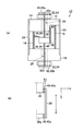
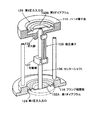
図1に本発明に係る圧力センサーの第1実施形態を示す。図1(a)は圧力センサーの概要図、図1(b)は感圧素子38の支持構造を示す部分詳細図である。第1実施形態に係る圧力センサー10は円筒形の外形を有し、ハウジング12、ダイアフラム32、力伝達手段34であるセンターシャフト36、感圧素子38から構成される。
FIG. 1 shows a first embodiment of a pressure sensor according to the present invention. FIG. 1A is a schematic diagram of a pressure sensor, and FIG. 1B is a partial detailed view showing a support structure of the pressure
ハウジング12は、内部を真空に封止して後述の各構成要素を収容するものである。これにより圧力センサー10は、感圧素子38のQ値を高め、安定した共振周波数を確保することができるので、圧力センサー10の長期安定性を確保することができる。
The
またハウジング12は上端面板を構成する円盤状の第1部材14、下端面板を構成する円盤上の第2部材16、第1部材14と第2部材16とを接合する支柱18、第1部材14及び第2部材16の側面を覆う円筒側壁を形成する第3部材20とから全体の外形が構成されている。第1部材14及び第2部材16は同一の直径を有する部材である。第1部材14及び第2部材16は、同心円を構成する位置に、それぞれ外部に突出する口金22を突出させ、この口金22に第1圧力入力口24、第2圧力入力口26を開口させている。そして第1部材14及び第1圧力入力口24(第2部材16及び第2圧力入力口26)を連通する貫通孔28が、前記同心円の中心位置に形成されている。
The
支柱18は、一定の剛性を有し、第1部材14及び第2部材16の互いに対向する位置に形成され、支柱18の断面の外形に倣った形状のダボ穴(不図示)に差し込んで接合することで、第1部材14、第2部材16、及び支柱18との間で剛性を獲得し、圧力センサー10の組み立て時、及び使用時に後述の感圧素子38に対する不要な歪みを抑えることができる。なお、図示では2本の支柱18が記載されているが、1本または3本以上用いてもよい。
The
ハウジング12の材質は、熱膨張による圧力センサー10の誤差を緩和するため、支柱18及び感圧素子38を収容する部分の周囲を熱膨張係数の小さい金属もしくはセラミックとすることが望ましい。
The material of the
そして、第1圧力入力口24および第2圧力入力口26には、測定対象の液体もしくは気体の圧力に応じて撓むダイアフラム32(第1ダイアフラム32a、第2ダイアフラム32b)が取り付けられ、貫通孔28を封止して外部に露出している。 The first pressure input port 24 and the second pressure input port 26 are attached with diaphragms 32 (first diaphragm 32a and second diaphragm 32b) that bend according to the pressure of the liquid or gas to be measured. 28 is sealed and exposed to the outside.
ダイアフラム32(第1ダイアフラム32a、第2ダイアフラム32b)は、一面が外部に面した受圧面となっており、前記受圧面が被測定圧力としての外部からの圧力を受けて撓み変形し、ダイアフラム32の他面の中央部32c、32dに接触(接続)している後述の力伝達手段34であるセンターシャフト36の端面に力を印加するものである。ダイアフラム32の材料は、ステンレスのような金属やセラミックなどの耐腐食性に優れたものがよく、また、水晶のような単結晶体やその他の非結晶体でもよい。またこのようなダイアフラム32は、プレス加工のように残留応力の発生がなく、小型化に有利なフォトリソグラフィー技法とエッチング技法とを用いて形成してもよい。
The diaphragm 32 (first diaphragm 32a, second diaphragm 32b) is a pressure receiving surface with one surface facing the outside, and the pressure receiving surface is deformed by receiving pressure from the outside as a pressure to be measured. A force is applied to an end surface of a center shaft 36 which is a force transmission means 34 described later that is in contact (connected) with the
なお、ダイアフラムは、液体やガス等により腐食しないように、外部に露出する表面をコーティングしてもよい。例えば、金属製のダイアフラムであれば、ニッケルの化合物をコーティングしてもよいし、ダイアフラムが水晶のような圧電結晶体であれば珪素をコーティングすればよい。 The diaphragm may be coated on the surface exposed to the outside so as not to be corroded by liquid or gas. For example, a nickel diaphragm may be coated with a nickel compound, and if the diaphragm is a piezoelectric crystal such as quartz, silicon may be coated.
第1ダイアフラム32aと第2ダイアフラム32bとの間には、力伝達手段34であるセンターシャフト36が貫通孔28を挿通して取り付けられ、センターシャフト36の両端部は第1ダイアフラム32aの中央部32c、及び第2ダイアフラム32bの中央部32dの面とそれぞれ垂直に接合している。よって、ダイアフラム32に圧力がかかってもセンターシャフト36と第1ダイアフラム32a及び第2ダイアフラム32bとの変位の方向は同じとなる。このとき圧力の高い側のダイアフラム32がハウジング12の内側に変位し、圧力の低い側のダイアフラム32がハウジング12の外側に変位するが、センターシャフト36の長さは変わらないので、変位の絶対値は両側で一致する。またセンターシャフト36の所定の位置には可動部材36aが固定され、この可動部材36aもセンターシャフト36と同じ変位方向を持つ。
Between the first diaphragm 32a and the second diaphragm 32b, a center shaft 36, which is a force transmission means 34, is inserted through the through
センターシャフト36は、強度が安定した材質であるステンレス、或いはアルミニウム、または加工のしやすいセラミックなどを、圧力センサーの用途に応じて選択して使用することにより、精度の高い安定した圧力センサーを構成することができる。特にセンターシャフト36の材料を熱膨張係数の小さい金属やセラミックにすると、圧力センサーの温度特性は、ほとんど感圧素子の温度特性に依存することになる。さらにセンターシャフト36の両端部は円形で、その中心をダイアフラム32の中心(中央部32c、32dの中心)と整合させて接続することが望ましい。
The center shaft 36 is a highly accurate and stable pressure sensor by selecting and using stainless steel, aluminum, which is a material with stable strength, or ceramic that can be easily processed according to the application of the pressure sensor. can do. In particular, when the material of the center shaft 36 is a metal or ceramic having a small thermal expansion coefficient, the temperature characteristics of the pressure sensor almost depend on the temperature characteristics of the pressure sensitive element. Furthermore, both ends of the center shaft 36 are circular, and it is desirable to connect the centers thereof with the centers of the diaphragms 32 (centers of the
感圧素子38は、水晶、ニオブ酸リチウム、タンタル酸リチウム等の圧電材料を用い、双音叉型圧電振動子、SAW共振子、厚みすべり振動子等として形成されたものである。感圧素子38は、可動部材36aと、第1部材14の固定部材30のそれぞれに感圧素子38の両端部を接続して支持されている。このとき、感圧素子38は力の検出方向を検出軸として設定しており、感圧素子38の前記両端部を結ぶ方向は前記検出軸と平行関係にある。また感圧素子38はハウジング12に取り付けられた発振回路(不図示)と電気的に接続され、発振回路(不図示)からの交流電圧により固有の共振周波数により振動する。そして、感圧素子38は可動部材38aからの伸長(引張)応力または圧縮応力を受けることにより共振周波数が変動する。特に双音叉型圧電振動子は、厚みすべり振動子などに比べて、伸長・圧縮応力に対する共振周波数の変化が極めて大きく共振周波数の可変幅が大きいので、わずかな圧力差を検出するような分解能力に優れる圧力センサーにおいては好適である。双音叉型圧電振動子は、伸長応力を受けると振動腕(振動部)の振幅幅が小さくなるので共振周波数が高くなり、圧縮応力を受けると振動腕(振動部)の振幅幅が大きくなるので共振周波数は低くなる。なお、双音叉型圧電振動子の圧電基板としては温度特性に優れた水晶が望ましい。
The pressure
このように構成した圧力センサーは、図1に示したように、例えば口金22の外周を雄ネジ構造とし、前記雄ネジに対応する雌ネジとなる取付金具42などを用いて測定対象となる液体もしくは気体の収容容器に取り付け、いずれか一方のダイアフラム32を、直接、測定対象に接触させる。取付金具42は測定対象となる液体等の圧力の大きさや、収容容器の構造により、所定の形状や肉厚のものが必要である。 As shown in FIG. 1, the pressure sensor configured as described above has a male screw structure on the outer periphery of the base 22, for example, and a liquid to be measured using a mounting bracket 42 that is a female screw corresponding to the male screw. Or it attaches to a gas container and either diaphragm 32 is made to contact a measuring object directly. The mounting bracket 42 needs to have a predetermined shape and thickness depending on the pressure level of the liquid to be measured and the structure of the storage container.
以上、説明したように、第1実施形態にかかる圧力センサーによれば、構成要素としてオイルを用いないので、オイル漏れ等の問題は生じない。そして、力伝達手段34は感圧素子38の端面方向からのみ力を伝達する動きをするため、圧力センサー10の感度を向上させることができた。
As described above, according to the pressure sensor according to the first embodiment, since oil is not used as a component, problems such as oil leakage do not occur. The force transmitting means 34 moves to transmit force only from the direction of the end face of the pressure
しかしながら、ここで、圧力センサーの感度が向上した反面、内在していた以下に示す如き別の問題が浮き彫りになった。
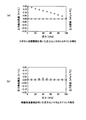
図1(b)に示すように、感圧素子38は、可動部材36aと、第1部材14の固定部材30のそれぞれに感圧素子38の両端部を、接着層40aを介して、支持されている。本願発明者は、当初、前述の特許文献1〜3に記載された圧力センサーで一般的に用いられているエポキシ系やシリコーン系の樹脂製接着剤を用いて感圧素子38の支持固定を試みた。図2(a)はエポキシ系接着剤を用いた場合の圧力センサー10の感度に係るヒステリシス特性を示すグラフである。圧力センサー10の第1圧力入力口24を大気雰囲気中に設置し、第1ダイアフラム32aに加わる圧力を大気圧(1atm=101325Pa≒101.3kPa)とし、一方、第2圧力入力口26を被測定圧力対象となる液体の中に浸し第2ダイアフラム32bに加わる圧力を101.3kPaとして、第1ダイアフラム32aと第2ダイアフラム32bとに加わる圧力の差、即ち差圧をゼロとしたところを基準とした。図2(a)は、前記差圧0Paの状態から100kPaとなるところまで第2圧力入力口26の第2ダイアフラム32bに圧力をかけていき、そのときに感圧素子38で検出する圧力と前記差圧との検出誤差と、ならびに100kPaに到達した後、前記差圧を100kPaから0Paまで低下させていったときに感圧素子38で検出する圧力と前記差圧との検出誤差とを、100kPaで除算したフルスケール(F.S.)の値を縦軸にプロットしたものである。
However, while the sensitivity of the pressure sensor has been improved, the following inherent problems have been highlighted.
As shown in FIG. 1B, the pressure-
エポキシ系接着剤を用いた場合、圧力を掛けていく段階では、検出誤差は観測されないが、逆に100kPaから下げていくほど、検出誤差が顕著に大きくなっていくことが観測されヒステリシス特性を有していることが判明した。 In the case of using an epoxy adhesive, no detection error is observed at the stage of applying pressure, but conversely, as the pressure is lowered from 100 kPa, it is observed that the detection error increases remarkably and has a hysteresis characteristic. Turned out to be.
この原因として、図1(b)に示すように力の検出軸方向をx軸とし、接着層40aの厚み方向をy軸とすると、ダイアフラム32が受圧した圧力はセンターシャフト36と可動部材36aを介して圧縮力或いは引張力Fとして感圧素子38に加わり、そのときに接着層40aに加わる力Fはx軸に平行な方向(接着層40aの接着面と平行な方向)に加わるのでせん断力として作用し、接着層40aにはせん断応力が生じることとなる。一方、接着層40aはエポキシ系の柔らかい樹脂接着剤であるため粘弾性変形し易い性質を有しているため、前記せん断応力を吸収し緩和してしまうので、その分だけ感圧素子38の感度を鈍らせてしまうという問題が起きているものと考えられる。
As a cause of this, when the force detection axis direction is the x axis and the thickness direction of the
それに対して、図8の如き従来構造においては、図8(b)に示すように、ベローズ506が受圧した圧力は力伝達部材505を介して力Fとして感圧素子38に伝達されることになるが、そのときに接着層40bに加わる力FはピボットPを支点として紙面に対して垂直方向を回転軸として円弧を描く方向に作用することになるので、力Fはx軸方向の成分とy軸方向の成分とに分力されることになる。x軸に平行な方向に加わる力Fxはせん断力として、y軸に平行な方向に加わる力Fyは圧縮力(或いは引張力)として作用する。従って、接着層40bにはせん断応力と圧縮応力(或いは引張応力)が生じることになる。このとき、前述の通り前記せん断応力は接着層40bの樹脂接着剤の粘弾性変形の影響により吸収されて緩和してしまうが、接着層40bの厚み方向については、接着層40bが感圧素子509と力伝達部材505とにより挟まれていることから粘弾性変形し難いため、圧縮応力(或いは引張応力)がほぼそのまま感圧素子509に伝達されるので、図1の構造に比べて圧力検出に影響を与えるほどの感度の劣化が生じなかったものと推察される。
On the other hand, in the conventional structure as shown in FIG. 8, the pressure received by the
本願発明者は、図1に示す如き構造を有する圧力センサー10においては、感圧素子38を支持固定する接着層40aを形成する接着手段の種類としては、感圧素子38をリジッドに固定することが妥当であると考え、無機系接着剤を採用することにより前述の如き課題を克服することができるのではないかということに思い至った。
In the
以下、詳細に説明するように、本願発明者はシミュレーションと実験を繰り返した結果、無機系接着剤40としては、酸化アルミニウムとSi化合物を含む接着剤が好適であることに想到した。特に本実施形態においては、商品名で示すと、(株)スリーボンド社製ThreeBondo3732(酸化アルミニウム、オルガノポリシロキサン縮合物を主成分とした無機系接着剤)、東亞合成(株)製アロンセラミックC、D(酸化アルミニウム、ケイ酸塩、ケイ砂地無機骨材、水を主成分とした無機系接着剤)、テルニック工業(株)社製ベタック820NF(W)、840A、900C(ケイ酸ナトリウム、酸化アルミニウム、二酸化ケイ素を主成分とする無機系接着剤)、ベタック1800LB(第一燐酸アルミニウム、二酸化ケイ素、無機顔料を含む水生懸濁液を主成分とする無機系接着剤)、アレムコプロダクト社製(輸入元:(株)オーデック)セラマボンド503(酸化アルミニウム、第一燐酸アルミニウム、水を主成分とする無機系接着剤)、セラマボンド552(アルミナ、ケイ酸塩を主成分とした無機系接着剤)、セラマボンド569(酸化アルミニウム、ケイ酸カリウムを主成分とした無機系接着剤)、セラマボンド571(メタケイ酸ナトリウムを主成分とした無機系接着剤)、セラマボンド671(酸化マグネシウム、アルミナを主成分とした無機系接着剤)、アレムコプロダクト社製(輸入元:(株)オーデック)ウルトラテンプ(ジルコニア、ケイ酸ジルコニウム、ケイ酸塩を主成分とした無機系接着剤)等が好適である。
Hereinafter, as described in detail, the inventor of the present application has repeated simulations and experiments, and as a result, has come up with the idea that an adhesive containing aluminum oxide and a Si compound is suitable as the
これらの無機系接着剤40の有する熱膨張係数は、水晶等の圧電素子の熱膨張係数に近い値を有するので、これらを用いることにより温度特性に優れた圧力センサーを構築できる。図2(b)は無機系接着剤40を用いた場合の圧力センサー10の圧力検出の感度に関わるヒステリシス特性を示す。このように、無機系接着剤を用いると、圧力を掛けていく過程、並びに圧力を100kPaから下げていく過程共に、検出誤差は観測されずヒステリシス特性が大幅に改善されていることが確認できた。つまり、接着層40aのx軸方向にせん断力が生じても接着層40aで吸収、緩和されずに、確実に感圧素子38に圧縮力(或いは引張力)として伝達されていることが分かった。
Since the thermal expansion coefficient of these
よって本実施形態のように、感圧素子と他の部材との間に形成される接着層にせん断方向の応力が掛かる場合には、無機系接着剤を使用することにより、ヒステリシス特性が解消されて、圧力センサーの圧力検出の誤差が改善され、特に低圧力領域(僅かな圧力変化)においては誤差を顕著に改善することができるので、極めて高精度な圧力センサーを提供することができる。 Therefore, as in this embodiment, when stress in the shear direction is applied to the adhesive layer formed between the pressure-sensitive element and another member, the hysteresis characteristic is eliminated by using an inorganic adhesive. Thus, the pressure detection error of the pressure sensor is improved, and particularly in the low pressure region (slight pressure change), the error can be remarkably improved, so that a highly accurate pressure sensor can be provided.
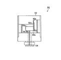
図3に第2実施形態に係る圧力センサー50を示す。第1実施形態の圧力センサー10は、大気圧をゼロ基準として表したゲージ圧を測定するものであったが、第2実施形態に係る圧力センサー50は真空状態をゼロ基準とした絶対圧力を測定するため、ハウジング52に接続された一つのダイアフラム54と、ダイアフラム54に接続され力伝達手段56であるセンターシャフト58と、センターシャフト58に固定される可動部材58a、ハウジング52に固定された固定部材52a、両端を可動部材58a及び固定部材52aに接続して支持された感圧素子60を有し、ハウジング52内部が真空封止された構成である。
FIG. 3 shows a
外部圧力が真空の場合は、ダイアフラム54に係る圧力はゼロとなり、ダイアフラム54は平板状になっている。そして、外部圧力が一定の圧力を有する場合は、ダイアフラム54はハウジング52内部側に変位し、これに伴いセンターシャフト58及び可動部材58aが変位することにより、感圧素子60の端面方向から圧縮力として加わることになる。
接着層40aの構造並びに材料は、前述の第1実施形態と同様であるため説明を省略する。
When the external pressure is vacuum, the pressure applied to the
Since the structure and material of the
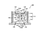
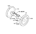
図4に第3実施形態に係る圧力センサー100を示し、図5、図6に同圧力センサーの部分破断斜視図、主要部品斜視図を示している。図示の第3実施形態の例は、第1実施形態に示した相対圧検出のための圧力センサー(図1)の変形例である。
FIG. 4 shows a
この圧力センサー100は、中空円筒体からなるハウジング112を有している。このハウジング112は第1部材(上端面板)をハーメ端子台114とするとともに、第2部材(下端面板)をフランジ端面板116とし、第3部材である円筒側壁120によって離隔配置した端面板の周囲を取り囲んで中空密閉容器として構成したものである。ハーメ端子台114とフランジ端面板116との各外面部には、ハウジング内部空間と連通する第1圧力入力口124、第2圧力入力口126が凹陥部として形成されており、その底板部分にハウジング112の軸芯と同芯の貫通孔128が穿設されて、内外を連通している。この圧力入力口124,126の凹陥部にはそれぞれ第1ダイアフラム132A、第2ダイアフラム132Bが嵌着され、その周囲の円筒部端縁をハーメ端子台114とフランジ端面板116とに一体的に溶着結合(ビード部130)し、これによって内外を遮蔽するようにされている。ハーメ端子台114側の第1ダイアフラム132Aは大気圧設定用であり、フランジ端面板116の第2ダイアフラム132Bは受圧用としている。このようなハウジング112も、内外が遮断された状態となっているとともに、図示しない空気抜き手段により内部を真空状態に保持できるようにしているのは第1実施形態と同様である。
The
前記ハウジング112の内部には、前記第1、第2のダイアフラム132A、132Bの内面の中央領域を相互に接続するセンターシャフト(力伝達手段)136がハウジング112の軸芯に沿って配置され、前記貫通孔128を貫通して両者を接着連結している。そして、このセンターシャフト136の途中には感圧素子受け台としての可動部137が一体的に設けられており、この可動部137に対して、検出軸を前記第1、第2ダイアフラム132(132A、132B)の受圧面と垂直な軸と平行に設定した双音叉型振動子からなる感圧素子138の一方の基部を取り付けるようにしている。感圧素子138の他方の基部は前記ハウジング112のハーメ端子台114に設けられている内側に突出した感圧素子受け台としてのボス部139に接続するようにしている。これにより、受圧用第2ダイアフラム132Bと大気圧用第1ダイアフラム132Aが受けた圧力の差圧によりセンターシャフト136が軸方向移動すると、これに追随して可動部137が位置を変動し、この力が感圧素子138の検出軸方向への作用力を発生させるようにしている。
Inside the
ダイアフラム132(132A、132B)は、外部圧力を受けて撓み変形する円盤状のダイアフラム本体(中央部)140と、当該ダイアフラム本体(中央部)140の周縁に一体的に設けられセンサーハウジング112の圧力入力口124、126の内壁面に嵌着可能な円筒部142とからなる。そして、この円筒部142の端縁に設けられた前記センサーハウジング112との溶着部(ビード部)130と前記ダイアフラム本体140の撓み基点となるダイアフラム本体外周縁部144との間に段差壁を形成している。特に、この実施形態では、溶着部(ビード部)130を、センサーハウジング112の圧力入力口124、126の開口縁部に接する前記円筒部先端縁とし、前記センサーハウジング112の開口縁に溶着するようにしたものである。
The diaphragm 132 (132A, 132B) is a disc-shaped diaphragm main body (center portion) 140 that is bent and deformed by receiving external pressure, and the pressure of the
上記ハウジング112の内部には、前記センターシャフト136と平行であって、その周囲に複数の支柱146が配置されている。これらは第2部材であるフランジ端面板116と第1部材であるハーメ端子台114との間隔を一定に保持し、外力によるハウジング112の変形や任意の姿勢によって検出精度が低下しないようにしているのは第1実施形態と同様である。
A plurality of
この第3実施形態では、特に、上部端面板をハーメ端子台114とし、これにはハーメ端子148をハーメ端子台114に貫通させ、感圧素子138の信号を外部に取り出すようにしている。
In the third embodiment, in particular, the upper end plate is the Herme
このような構成に加えて、本実施形態では、双音叉型振動子からなる実施形態の感圧素子138は、その一端側の取付基部を上記可動部137に固定し、他端側の取付基部を上述したハーメ端子台114のボス部139に固定するようにしている。感圧素子138の固定のために、酸化アルミニウムとSi化合物を含む無機系接着剤が用いられ、接着層150として感圧素子138の基部とその接合対象面との間に介在している。これにより圧力検査によって繰返しボス部139に対して可動部137が近接離反動作をして、接着層150に当該接着層150の接着面と平行な方向にせん断応力が掛かることになる。しかし、接着層150は無機系接着剤によりリジッドに形成されるため、上述のせん断応力は接着層で吸収・緩和されずに、確実に感圧素子138に伝達されるため、圧力検出の誤差が改善された高精度な圧力センサーとすることができる。したがって、相対圧センサーとしてオイルレスで小型の圧力センサーとすることができるとともに、感圧素子138には検出軸方向の力のみを作用させることが可能で、検出精度が向上する。
In addition to such a configuration, in the present embodiment, the pressure-
このような第3実施形態によれば、一対のダイアフラム132同士はセンターシャフト136により連結され、センターシャフト136の途中に設けた可動部137がダイアフラム132の挙動に応じて一体的にシャフト軸方向に移動し(これが一対のダイアフラム132A,132Bが受ける圧力差に起因する動きとなる。)、双音叉型振動子である感圧素子138の検出軸方向に作用する力に応じた動きとなる。したがって、オイルを用いることなく、検出精度の高い圧力センサーを構成でき、かつ小型で組み立てが容易な構造となる。また、フランジ端面板116、ハーメ端子台114、並びに円筒側壁120が真空容器としてのハウジング112を形成し、ハーメ端子台114と第1ダイアフラム132Aが一体とされ、フランジ端面板116と第2ダイアフラム132Bとが一体とされ、組み立てが簡便に行えるようにしている。この圧力センサー100を測定対象液体へ沈める(浸す)容器に取り付けるには、フランジ端面板116を測定対象液体容器に第2ダイアフラム132Bの周囲を囲むように配置されたOリングを介して面接合してボルト締めにより取り付ける。この取付作業に際して、第1実施形態のようにセンターシャフトを連結したダイアフラムを備えた口金部分で捩じ込みする構成とならないので、センターシャフトの伸びに起因して感圧素子へ引っ張り力を与えるような不具合を防止できる。
According to the third embodiment, the pair of diaphragms 132 are connected to each other by the
なお、この第3実施形態でも、センターシャフト136と感圧素子固定用受け台としての可動部137は、一つの部材から切削加工された一体のものであっても良い。そうすることにより可動部137がシャフトの固定部でブレたり、ずれることがなくなる。
In the third embodiment as well, the
また、第3実施形態では、ダイアフラム132をハーメ端子台114とフランジ端面板116の外面に凹陥部として形成した圧力入力口124,126に嵌着して取り付けるため、ハウジング112には外部への突出部分が無くなり、高さ寸法を短くすることができて、小型化を促進することができるものとなっている。
In the third embodiment, the diaphragm 132 is fitted and attached to the
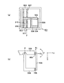
次に、図7には、第4実施形態に係る圧力センサー200の断面図を示している。図示の例は、絶対圧検出のための圧力センサーとした例である。すなわち、第3実施形態の大気圧検出用の第1ダイアフラム132Aを取り除いて、単に第1部材をハーメ端子台としてハウジングを密閉するように形成したものである。そして、特にセンターシャフトと感圧素子を同芯配置し、これらを受圧用ダイアフラムの中央領域を通る軸線上に配置した点が先の実施形態と異なる。
Next, FIG. 7 shows a cross-sectional view of a
この圧力センサー200は、中空円筒体からなるハウジング212を有している。このハウジング212は第1部材(上端面板)をハーメ端子台214とするとともに、第2部材(下端面板)を構成する端面板を第3実施形態と同様なフランジ端面板216とし、第3のケースである円筒側壁220によって離隔配置した端面板の周囲を取り囲んで中空密閉容器として構成している。フランジ端面板216には、内部空間と連通する圧力入力口226がハウジング212の軸芯と同芯に貫通されて、凹陥部を形成してその中央部に貫通孔228を形成し、凹陥部にダイアフラム232を嵌着してハウジングの内外を遮蔽している。ダイアフラム232は圧力入力口226の凹陥部内壁に接着されて一体的に結合している。ダイアフラム232は測定対象液体の受圧用である。ハーメ端子台214には圧力流入口もダイアフラムも省略された端面板として構成されている。このようなハウジング212も、内外が遮断された状態となっているとともに、図示しない空気抜き手段により内部を真空状態に保持できるようにしているのは他の実施形態と同様である。
The
前記ハウジング212の内部には、前記ダイアフラム232の内面の中央領域240にセンターシャフト(力伝達手段)236が垂直に立設されており、これはハウジング212の軸芯に沿って配置されている。そして、このセンターシャフト236の先端部には感圧素子受け台としての可動部237が一体的に設けられており、この可動部237に検出軸をセンターシャフト236と同軸となるように設定した双音叉型振動子からなる感圧素子238の一端部を取り付けるようにしている。感圧素子238の他端部は前記ハウジング212のハーメ端子台214の中央領域に設けられている内側に突出した台座215に接続するようにしている。これにより、受圧用ダイアフラム232が測定対象液体の圧力を受けることにより撓むと、センターシャフト236が軸方向に移動し、これに追随して可動部237に連結された感圧素子238の検出軸方向への作用力を発生させるようにしている。
Inside the housing 212, a center shaft (force transmission means) 236 is erected vertically in a central region 240 on the inner surface of the
この第4実施形態においても、感圧素子238の固定のために、酸化アルミニウムとSi化合物を含む無機系接着剤が用いられるようになっており、接着層250が感圧素子238の検出軸方向の両端基部先端部とその接合対象面との間に介在している。これにより圧力検査によって感圧素子238が圧縮・引張力を受けても、接着層250の厚み方向に圧縮または引張力が掛かることになる。しかし、接着層250は無機系接着剤によりリジッドに形成されるため、上述の圧縮または引張力は接着層250で吸収・緩和されずに、剛体結合層となって確実に感圧素子238に伝達されるため、圧力検出の誤差が改善され、感度を高く保つことができる。このようなことから、絶対圧センサーとしてオイルレスで小型の圧力センサーとすることができるとともに、感圧素子には検出軸方向の力のみを作用させることが可能で、検出精度が向上する。
Also in the fourth embodiment, an inorganic adhesive containing aluminum oxide and a Si compound is used for fixing the pressure
なお、上記ハウジング212の内部には、前記センターシャフト236と平行であって、その周囲に複数の支柱246が配置されている。これらは第2部材であるフランジ端面板216と第1部材であるハーメ端子台214との間隔を一定に保持し、外力によるハウジング212の変形や任意の姿勢によって検出精度が低下しないようにしているのは他の実施形態と同様である。
Note that a plurality of
この第4実施形態も第3実施形態と同様に、上部端面板をハーメ端子台214とし、これには図示しないハーメ端子248を端子台214に貫通させ、感圧素子238の信号を外部に取り出すようにしている。
In the fourth embodiment, similarly to the third embodiment, the upper end face plate is used as a hermetic
このような第4実施形態によれば、フランジ端面板216、ハーメ端子台214、並びに円筒側壁220が真空容器としてのハウジング212を形成し、フランジ端面板216とダイアフラム232とが一体とされ、組み立てが簡便に行えるようにしている。受圧用のダイアフラム232とセンターシャフト236とは同心的に一直線上に連結され、センターシャフト236の先端に設けた可動部237がダイアフラム232の挙動に応じてシャフト軸方向に移動し、双音叉型振動子である感圧素子238の検出軸方向に作用する力を生じさせる。したがって、オイルを用いることなく、検出精度の高い圧力センサーを構成でき、かつ小型で組み立てが容易な構造となる。
According to the fourth embodiment, the flange
なお、この第4実施形態でも、センターシャフト236と感圧素子固定用受け台としての可動部237は、一つの部材から切削加工された一体のものであっても良い。そうすることにより可動部237がシャフトの固定部でぶれたり、ずれることがなくなる。
In the fourth embodiment as well, the
10………圧力センサー、12………ハウジング、14………第1部材、16………第2部材、18………支柱、20………第3部材、22………口金、24………第1圧力入力口、26………第2圧力入力口、28………貫通孔、30………固定部材、32………ダイアフラム、34………力伝達手段、36………センターシャフト、38………感圧素子、40………無機系接着剤、42………取付金具、50………圧力センサー、52………ハウジング、54………ダイアフラム、56………力伝達手段、58………センターシャフト、60………感圧素子、100………圧力センサー、102………第1の圧力入力口、103………第2の圧力入力口、104………筐体、105………力伝達部材、106………第1のベローズ、107………第2のベローズ、108………基板、109………双音叉型振動子、110………オイル、111………開口部、112………ハウジング、114………ハーメ端子台、116………フランジ端面板、124………第1圧力入力口、126………第2圧力入力口、128………貫通孔、130………ビード部、132A………第1ダイアフラム、132B………第2ダイアフラム、136………センターシャフト、137………可動部、138………感圧素子、139………ボス部、140………ダイアフラム本体、142………円筒部、144………ダイアフラム本体外周縁部、146………支柱、148………ハーメ端子、150………接着層、200………圧力センサー、212………ハウジング、214………ハーメ端子台、215………台座、216………フランジ端面板、226………圧力入力口、228………貫通孔、232………ダイアフラム、236………センターシャフト、237………可動部、238………感圧素子、246………支柱、248………ハーメ端子、250………接着層。
10 ......... Pressure sensor, 12 ......... Housing, 14 ......... First member, 16 ......... Second member, 18 ......... Posts, 20 ......... Third member, 22 ......... Base, 24 ......... First pressure input port, 26 ......... Second pressure input port, 28 ......... Through hole, 30 ......... Fixing member, 32 ......... Diaphragm, 34 ......... Force transmitting means, 36 ... ... Center shaft, 38 ... Pressure-sensitive element, 40 ... Inorganic adhesive, 42 ... Mounting bracket, 50 ... Pressure sensor, 52 ... Housing, 54 ... Diaphragm, 56 ... ... Force transmission means 58...
Claims (11)
前記ハウジングに形成した口金部に開口させた圧力入力口と、
前記圧力入力口を封止し、一面が受圧面であるダイアフラムと、
前記ハウジングの内部から前記ダイアフラムの他面の中央部に接続した力伝達手段と、
力の検出方向を検出軸とする感圧素子とを有し、
前記力伝達手段の変位方向及び前記検出軸の方向は前記受圧面に対してほぼ垂直であり、
前記感圧素子の一端は前記ハウジングに、他端は前記力伝達手段に、接着手段を介して支持固定され、
前記接着手段が無機系接着剤であることを特徴とする圧力センサー。 A housing;
A pressure input port opened in a base portion formed in the housing;
Sealing the pressure input port, a diaphragm whose one surface is a pressure receiving surface;
Force transmitting means connected from the inside of the housing to the center of the other surface of the diaphragm;
A pressure-sensitive element having the detection direction of force as a detection axis,
The displacement direction of the force transmission means and the direction of the detection axis are substantially perpendicular to the pressure receiving surface,
One end of the pressure-sensitive element is supported and fixed to the housing and the other end to the force transmission means via an adhesive means,
The pressure sensor, wherein the bonding means is an inorganic adhesive.
両端部に設けた基部を有し、
前記両端部に設けた基部の間に振動部を有することを特徴とする請求項1または2に記載の圧力センサー。 The pressure sensitive element is:
Having a base provided at both ends,
The pressure sensor according to claim 1, further comprising a vibrating portion between base portions provided at both ends.
当該ハウジングの前記圧力入力口を封止し外面が受圧面であるダイアフラムと、
前記ハウジング内部にて前記ダイアフラムの中央領域に接続され当該ダイアフラムに連動してその受圧面と垂直方向に動く力伝達手段と、
この力伝達手段と前記ハウジングに接続されて検出軸を前記ダイアフラムの受圧面と垂直な軸に沿って設定した感圧素子とを有してなり、
前記感圧素子は、その基部が無機系接着剤により前記力伝達手段と前記ハウジングダイアフラムに接着されていることを特徴とする圧力センサー。 A housing having a pressure input port;
A diaphragm whose outer surface is a pressure receiving surface that seals the pressure input port of the housing;
A force transmission means connected to a central region of the diaphragm inside the housing and moving in a direction perpendicular to the pressure receiving surface in conjunction with the diaphragm;
The force transmission means and a pressure sensitive element connected to the housing and having a detection axis set along an axis perpendicular to the pressure receiving surface of the diaphragm,
The pressure sensor is characterized in that the base of the pressure sensitive element is bonded to the force transmitting means and the housing diaphragm by an inorganic adhesive.
当該ハウジングの対向する端面板に同軸上に設けられた一対の圧力入力口と、
前記圧力入力口を封止し外面が受圧面である第1、第2のダイアフラムと、
前記ハウジング内部にて前記ダイアフラムの内面の中央領域同士を接続する力伝達手段と、
この力伝達手段の途中に一端を接続され他端を前記ハウジングに接続するとともに、検出軸を前記ダイアフラムの受圧面と垂直な軸と平行に配列された感圧素子とを有してなり、
前記感圧素子は、その基部が無機系接着剤により前記力伝達手段と前記ハウジングダイアフラムに接着されていることを特徴とする圧力センサー。 A housing;
A pair of pressure input ports provided coaxially on opposite end plates of the housing;
First and second diaphragms that seal the pressure input port and whose outer surface is a pressure receiving surface;
A force transmission means for connecting central regions of the inner surface of the diaphragm inside the housing;
One end is connected in the middle of the force transmission means, the other end is connected to the housing, and a detection shaft is arranged in parallel with an axis perpendicular to the pressure receiving surface of the diaphragm,
The pressure sensor is characterized in that the base of the pressure sensitive element is bonded to the force transmitting means and the housing diaphragm by an inorganic adhesive.
当該ハウジングの端面板に設けられた圧力入力口と、
前記圧力入力口を封止し外面が受圧面であるダイアフラムと、
前記ハウジング内部にて前記ダイアフラムの内面の中央領域に当該ダイアフラムの受圧面と垂直な軸線上に配置され対向するハウジング端面板と接続される力伝達手段と、
この力伝達手段の途中に一端を接続され他端を前記ハウジングに接続するとともに、
検出軸を前記ダイアフラムの受圧面と垂直な軸と同軸に設定した感圧素子とを有してなり、
前記感圧素子は、その基部が無機系接着剤により前記力伝達手段と前記ハウジングダイアフラムに接着されていることを特徴とする圧力センサー。 A housing;
A pressure input port provided in an end plate of the housing;
A diaphragm that seals the pressure input port and whose outer surface is a pressure-receiving surface;
A force transmission means disposed on the axis perpendicular to the pressure receiving surface of the diaphragm in the central region of the inner surface of the diaphragm inside the housing and connected to an opposing housing end face plate;
One end is connected in the middle of this force transmission means and the other end is connected to the housing,
A pressure sensitive element having a detection axis set coaxially with an axis perpendicular to the pressure receiving surface of the diaphragm;
The pressure sensor is characterized in that the base of the pressure sensitive element is bonded to the force transmitting means and the housing diaphragm by an inorganic adhesive.
感圧素子を前記センターシャフトと平行に配置したことを特徴とする請求項4〜6のいずれか1項に記載の圧力センサー。 The force transmission means is formed by a center shaft;
The pressure sensor according to any one of claims 4 to 6, wherein a pressure sensitive element is arranged in parallel with the center shaft.
前記第1、第2部材に開口された圧力入力口を封止する第1、第2のダイアフラムと、
前記ハウジング内にて前記第1、第2ダイアフラム同士をその中央領域で連結して一体化され力の伝達を可能としたセンターシャフトと、
このセンターシャフトに固定された可動台と前記ハウジング内面部に設けた固定台とに両端部が取り付けられ検出軸を前記センターシャフトと平行に設定された感圧素子と、
前記センターシャフトの周囲に配置され第1、第2の部材同士を連結する複数のガイドセンターシャフトを有してなり、
前記感圧素子は、その基部が無機系接着剤により前記力伝達手段と前記ハウジングダイアフラムに接着されていることを特徴とする圧力センサー。 A housing formed by first and second members forming end plates facing each other and a third member surrounding the periphery and forming a side member;
First and second diaphragms for sealing pressure input ports opened in the first and second members;
A center shaft in which the first and second diaphragms are connected to each other in the central region in the housing and integrated to enable transmission of force;
A pressure sensitive element having both ends attached to a movable base fixed to the center shaft and a fixed base provided on the inner surface of the housing, and a detection axis set parallel to the center shaft;
It has a plurality of guide center shafts arranged around the center shaft and connecting the first and second members,
The pressure sensor is characterized in that the base of the pressure sensitive element is bonded to the force transmitting means and the housing diaphragm by an inorganic adhesive.
前記第1の部材に開口された圧力入力口を封止する第1ダイアフラムと、前記ハウジング内にて前記第1ダイアフラムの中央領域で連結して一体化され力の伝達を可能としたセンターシャフトと、
このセンターシャフトの端部に固定された可動受け台と前記第2部材内面部に設けた固定受け台とに両端部が取り付けられ検出軸を前記センターシャフトと同軸に設定された感圧素子と、
前記センターシャフトの周囲に配置され第1、第2の部材同士を連結する複数のガイドシャフトを有してなり、
前記感圧素子は、その基部が無機系接着剤により前記力伝達手段と前記ハウジングダイアフラムに接着されていることを特徴とする圧力センサー。 A housing formed by first and second members forming end plates facing each other and a third member surrounding the periphery and forming a side member;
A first diaphragm that seals a pressure input port opened in the first member; and a center shaft that is connected and integrated in a central region of the first diaphragm in the housing to transmit force. ,
A pressure-sensitive element having both ends attached to a movable cradle fixed to the end of the center shaft and a fixed cradle provided on the inner surface of the second member, and a detection axis set coaxially with the center shaft;
It has a plurality of guide shafts arranged around the center shaft and connecting the first and second members.
The pressure sensor is characterized in that the base of the pressure sensitive element is bonded to the force transmitting means and the housing diaphragm by an inorganic adhesive.
Priority Applications (3)
| Application Number | Priority Date | Filing Date | Title |
|---|---|---|---|
| JP2009027765A JP2010019829A (en) | 2008-06-11 | 2009-02-09 | Pressure sensor |
| US12/480,226 US7895896B2 (en) | 2008-06-11 | 2009-06-08 | Pressure sensor |
| CN200910147417XA CN101603871B (en) | 2008-06-11 | 2009-06-10 | Pressure sensor |
Applications Claiming Priority (2)
| Application Number | Priority Date | Filing Date | Title |
|---|---|---|---|
| JP2008153257 | 2008-06-11 | ||
| JP2009027765A JP2010019829A (en) | 2008-06-11 | 2009-02-09 | Pressure sensor |
Publications (1)
| Publication Number | Publication Date |
|---|---|
| JP2010019829A true JP2010019829A (en) | 2010-01-28 |
Family
ID=41413529
Family Applications (1)
| Application Number | Title | Priority Date | Filing Date |
|---|---|---|---|
| JP2009027765A Withdrawn JP2010019829A (en) | 2008-06-11 | 2009-02-09 | Pressure sensor |
Country Status (3)
| Country | Link |
|---|---|
| US (1) | US7895896B2 (en) |
| JP (1) | JP2010019829A (en) |
| CN (1) | CN101603871B (en) |
Cited By (3)
| Publication number | Priority date | Publication date | Assignee | Title |
|---|---|---|---|---|
| KR101114673B1 (en) * | 2009-08-28 | 2012-03-13 | 세이코 엡슨 가부시키가이샤 | Pressure sensor |
| JP2013104753A (en) * | 2011-11-11 | 2013-05-30 | Seiko Epson Corp | Physical quantity detector |
| JP2018531594A (en) * | 2015-09-11 | 2018-11-01 | フィリップ・モーリス・プロダクツ・ソシエテ・アノニム | Multi-segment components for aerosol generating articles |
Families Citing this family (10)
| Publication number | Priority date | Publication date | Assignee | Title |
|---|---|---|---|---|
| JP2010019828A (en) * | 2008-06-11 | 2010-01-28 | Epson Toyocom Corp | Diaphragm for pressure sensor, and pressure sensor |
| JP2012058024A (en) * | 2010-09-07 | 2012-03-22 | Seiko Epson Corp | Pressure sensor |
| JP2012073163A (en) | 2010-09-29 | 2012-04-12 | Seiko Epson Corp | Pressure sensor |
| JP2012093135A (en) * | 2010-10-25 | 2012-05-17 | Seiko Epson Corp | Pressure sensor |
| CN107543688B (en) * | 2016-11-14 | 2019-03-22 | 北京卫星环境工程研究所 | Rocket launching section rectifies internal mask pressure simulation experiment system |
| WO2020079773A1 (en) * | 2018-10-17 | 2020-04-23 | Q’z株式会社 | Pressure meter |
| CN109682530B (en) * | 2018-12-24 | 2024-03-22 | 武汉中航传感技术有限责任公司 | Layered differential pressure sensor |
| CN113358262B (en) * | 2021-07-22 | 2023-02-28 | 中车大同电力机车有限公司 | Ferrule type joint pull-out force detection device and method |
| CN114295260B (en) * | 2021-12-29 | 2024-03-26 | 福建省锅炉压力容器检验研究院 | Weld joint residual stress reliability simulation test device |
| CN116296033B (en) * | 2023-02-16 | 2025-11-11 | 四川新川航空仪器有限责任公司 | Diaphragm assembly and sensor |
Citations (4)
| Publication number | Priority date | Publication date | Assignee | Title |
|---|---|---|---|---|
| JPS60231129A (en) * | 1984-05-01 | 1985-11-16 | Kyowa Dengiyou:Kk | Pressure converter |
| JPH07253374A (en) * | 1994-03-14 | 1995-10-03 | Nippondenso Co Ltd | Pressure detection device |
| JP2005172761A (en) * | 2003-12-15 | 2005-06-30 | Denso Corp | Pressure sensor |
| JP2008020337A (en) * | 2006-07-13 | 2008-01-31 | Epson Toyocom Corp | Pressure sensor |
Family Cites Families (29)
| Publication number | Priority date | Publication date | Assignee | Title |
|---|---|---|---|---|
| US4215570A (en) * | 1979-04-20 | 1980-08-05 | The United States Of America As Represented By The United States Department Of Energy | Miniature quartz resonator force transducer |
| DE2935476B2 (en) * | 1979-09-01 | 1981-07-09 | Hottinger Baldwin Messtechnik Gmbh, 6100 Darmstadt | Liquid-filled differential pressure transducer |
| US4321500A (en) * | 1979-12-17 | 1982-03-23 | Paroscientific, Inc. | Longitudinal isolation system for flexurally vibrating force transducers |
| US4406966A (en) * | 1980-01-28 | 1983-09-27 | Paroscientific, Inc. | Isolating and temperature compensating system for resonators |
| US4382385A (en) * | 1980-04-17 | 1983-05-10 | Paroscientific, Inc. | Digital differential pressure transducer |
| US4372173A (en) * | 1980-10-20 | 1983-02-08 | Quartex, Inc. | Resonator force transducer |
| US4384495A (en) * | 1980-11-17 | 1983-05-24 | Quartex, Inc. | Mounting system for applying forces to load-sensitive resonators |
| US4455874A (en) * | 1981-12-28 | 1984-06-26 | Paroscientific, Inc. | Digital pressure transducer |
| JPS649331U (en) | 1987-07-07 | 1989-01-19 | ||
| JPS6486608A (en) | 1987-09-28 | 1989-03-31 | Toyo Communication Equip | Structure of piezoelectric vibrator |
| JPH02228534A (en) | 1989-03-02 | 1990-09-11 | Toyo Commun Equip Co Ltd | Pressure sensor |
| JPH0719981A (en) | 1993-06-01 | 1995-01-20 | Nippondenso Co Ltd | High-temperature pressure sensor |
| JPH08159900A (en) | 1994-12-05 | 1996-06-21 | Fuji Electric Co Ltd | Method for manufacturing pressure-sensitive diaphragm for pressure sensor |
| US6497152B2 (en) * | 2001-02-23 | 2002-12-24 | Paroscientific, Inc. | Method for eliminating output discontinuities in digital pressure transducers and digital pressure transducer employing same |
| US6595054B2 (en) * | 2001-05-14 | 2003-07-22 | Paroscientific, Inc. | Digital angular rate and acceleration sensor |
| US6813960B1 (en) * | 2002-08-19 | 2004-11-09 | Southwest Research Institute | Asymmetrical column assembly for high-cycle fatigue test machines |
| JP4638659B2 (en) | 2003-05-21 | 2011-02-23 | 株式会社豊田中央研究所 | Pressure sensor |
| JP2005017050A (en) | 2003-06-25 | 2005-01-20 | Toyo Commun Equip Co Ltd | Quartz pressure sensor and water level meter using it |
| JP4586441B2 (en) | 2003-09-24 | 2010-11-24 | エプソントヨコム株式会社 | Pressure sensor |
| US6938334B2 (en) * | 2003-10-31 | 2005-09-06 | Honeywell International, Inc. | Vibrating beam accelerometer two-wafer fabrication process |
| JP2006194736A (en) | 2005-01-13 | 2006-07-27 | Denso Corp | Pressure detection device and its manufacturing method |
| JP2007057395A (en) | 2005-08-24 | 2007-03-08 | Epson Toyocom Corp | Pressure sensor |
| JP2007132697A (en) | 2005-11-08 | 2007-05-31 | Denso Corp | Pressure sensor |
| US7467553B2 (en) * | 2005-12-22 | 2008-12-23 | Honeywell International Inc. | Capacitively coupled resonator drive |
| JP2008232886A (en) | 2007-03-22 | 2008-10-02 | Epson Toyocom Corp | Pressure sensor |
| JP2010019826A (en) * | 2008-03-25 | 2010-01-28 | Epson Toyocom Corp | Pressure sensor |
| JP2010019827A (en) * | 2008-06-11 | 2010-01-28 | Epson Toyocom Corp | Pressure sensor |
| JP2010019828A (en) * | 2008-06-11 | 2010-01-28 | Epson Toyocom Corp | Diaphragm for pressure sensor, and pressure sensor |
| JP4756394B2 (en) * | 2009-03-04 | 2011-08-24 | セイコーエプソン株式会社 | pressure sensor |
-
2009
- 2009-02-09 JP JP2009027765A patent/JP2010019829A/en not_active Withdrawn
- 2009-06-08 US US12/480,226 patent/US7895896B2/en not_active Expired - Fee Related
- 2009-06-10 CN CN200910147417XA patent/CN101603871B/en not_active Expired - Fee Related
Patent Citations (4)
| Publication number | Priority date | Publication date | Assignee | Title |
|---|---|---|---|---|
| JPS60231129A (en) * | 1984-05-01 | 1985-11-16 | Kyowa Dengiyou:Kk | Pressure converter |
| JPH07253374A (en) * | 1994-03-14 | 1995-10-03 | Nippondenso Co Ltd | Pressure detection device |
| JP2005172761A (en) * | 2003-12-15 | 2005-06-30 | Denso Corp | Pressure sensor |
| JP2008020337A (en) * | 2006-07-13 | 2008-01-31 | Epson Toyocom Corp | Pressure sensor |
Cited By (5)
| Publication number | Priority date | Publication date | Assignee | Title |
|---|---|---|---|---|
| KR101114673B1 (en) * | 2009-08-28 | 2012-03-13 | 세이코 엡슨 가부시키가이샤 | Pressure sensor |
| JP2013104753A (en) * | 2011-11-11 | 2013-05-30 | Seiko Epson Corp | Physical quantity detector |
| JP2018531594A (en) * | 2015-09-11 | 2018-11-01 | フィリップ・モーリス・プロダクツ・ソシエテ・アノニム | Multi-segment components for aerosol generating articles |
| JP2019088315A (en) * | 2015-09-11 | 2019-06-13 | フィリップ・モーリス・プロダクツ・ソシエテ・アノニム | Multi-segment component for aerosol-generating article |
| US10729169B2 (en) | 2015-09-11 | 2020-08-04 | Philip Morris Products S.A. | Multi-segment component for an aerosol-generating article |
Also Published As
| Publication number | Publication date |
|---|---|
| CN101603871B (en) | 2011-11-02 |
| CN101603871A (en) | 2009-12-16 |
| US7895896B2 (en) | 2011-03-01 |
| US20090308164A1 (en) | 2009-12-17 |
Similar Documents
| Publication | Publication Date | Title |
|---|---|---|
| CN101603870B (en) | Diaphragm for pressure sensor and pressure sensor | |
| JP2010019829A (en) | Pressure sensor | |
| CN101603869B (en) | Pressure sensor | |
| US7942062B2 (en) | Pressure sensor and method for manufacturing the same | |
| CN101545816B (en) | Pressure sensor | |
| US8297124B2 (en) | Pressure sensor | |
| JP4756394B2 (en) | pressure sensor | |
| JP5915103B2 (en) | Physical quantity detector | |
| JP2012093135A (en) | Pressure sensor | |
| JP2012037415A (en) | Pressure sensor | |
| JP2012168204A (en) | Pressure sensor | |
| JP2010025582A (en) | Pressure sensor | |
| JP2011013190A (en) | Force detector and housing for force detector | |
| JP2010014572A (en) | Pressure sensor | |
| KR101114673B1 (en) | Pressure sensor | |
| JP2012058063A (en) | Pressure sensor | |
| JP2010210544A (en) | Pressure sensor | |
| JP2011013010A (en) | Method of manufacturing force detector and force detector | |
| JP2011027523A (en) | Pressure sensor | |
| TW201105942A (en) | Pressure sensor |
Legal Events
| Date | Code | Title | Description |
|---|---|---|---|
| A621 | Written request for application examination |
Free format text: JAPANESE INTERMEDIATE CODE: A621 Effective date: 20101020 |
|
| A711 | Notification of change in applicant |
Free format text: JAPANESE INTERMEDIATE CODE: A712 Effective date: 20110729 |
|
| RD03 | Notification of appointment of power of attorney |
Free format text: JAPANESE INTERMEDIATE CODE: A7423 Effective date: 20110729 |
|
| A521 | Request for written amendment filed |
Free format text: JAPANESE INTERMEDIATE CODE: A523 Effective date: 20110819 |
|
| A521 | Request for written amendment filed |
Free format text: JAPANESE INTERMEDIATE CODE: A523 Effective date: 20110915 |
|
| A131 | Notification of reasons for refusal |
Free format text: JAPANESE INTERMEDIATE CODE: A131 Effective date: 20120514 |
|
| A977 | Report on retrieval |
Free format text: JAPANESE INTERMEDIATE CODE: A971007 Effective date: 20120516 |
|
| A761 | Written withdrawal of application |
Free format text: JAPANESE INTERMEDIATE CODE: A761 Effective date: 20120625 |