JP2010019472A - Air conditioner - Google Patents

Air conditioner Download PDF

Info

Publication number
JP2010019472A
JP2010019472A JP2008179476A JP2008179476A JP2010019472A JP 2010019472 A JP2010019472 A JP 2010019472A JP 2008179476 A JP2008179476 A JP 2008179476A JP 2008179476 A JP2008179476 A JP 2008179476A JP 2010019472 A JP2010019472 A JP 2010019472A
Authority
JP
Japan
Prior art keywords
refrigerant
indoor
unit
expansion
pipe
Prior art date
Legal status (The legal status is an assumption and is not a legal conclusion. Google has not performed a legal analysis and makes no representation as to the accuracy of the status listed.)
Granted
Application number
JP2008179476A
Other languages
Japanese (ja)
Other versions
JP5217710B2 (en
Inventor
Shingo Onishi
新吾 大西
Current Assignee (The listed assignees may be inaccurate. Google has not performed a legal analysis and makes no representation or warranty as to the accuracy of the list.)
Daikin Industries Ltd
Original Assignee
Daikin Industries Ltd
Priority date (The priority date is an assumption and is not a legal conclusion. Google has not performed a legal analysis and makes no representation as to the accuracy of the date listed.)
Filing date
Publication date
Application filed by Daikin Industries Ltd filed Critical Daikin Industries Ltd
Priority to JP2008179476A priority Critical patent/JP5217710B2/en
Publication of JP2010019472A publication Critical patent/JP2010019472A/en
Application granted granted Critical
Publication of JP5217710B2 publication Critical patent/JP5217710B2/en
Active legal-status Critical Current
Anticipated expiration legal-status Critical

Links

Images

Classifications

    • YGENERAL TAGGING OF NEW TECHNOLOGICAL DEVELOPMENTS; GENERAL TAGGING OF CROSS-SECTIONAL TECHNOLOGIES SPANNING OVER SEVERAL SECTIONS OF THE IPC; TECHNICAL SUBJECTS COVERED BY FORMER USPC CROSS-REFERENCE ART COLLECTIONS [XRACs] AND DIGESTS
    • Y02TECHNOLOGIES OR APPLICATIONS FOR MITIGATION OR ADAPTATION AGAINST CLIMATE CHANGE
    • Y02BCLIMATE CHANGE MITIGATION TECHNOLOGIES RELATED TO BUILDINGS, e.g. HOUSING, HOUSE APPLIANCES OR RELATED END-USER APPLICATIONS
    • Y02B30/00Energy efficient heating, ventilation or air conditioning [HVAC]
    • Y02B30/70Efficient control or regulation technologies, e.g. for control of refrigerant flow, motor or heating

Landscapes

  • Other Air-Conditioning Systems (AREA)
  • Air Conditioning Control Device (AREA)

Abstract

<P>PROBLEM TO BE SOLVED: To hardly cause a problem of a sound when a refrigerant passes through electric expansion valves in an air conditioner constituted by connecting a plurality of indoor units to an outdoor unit. <P>SOLUTION: The air conditioner 1 constituted by connecting the plurality of indoor units 3, 4, 5 to the outdoor unit 2 is constituted to provide electric expansion valves 31, 41, 51 for controlling the flow rate of a refrigerant flowing through the respective indoor units 3, 4, 5, as expansion units 6, 7, 8 different from the indoor units 3, 4, 5 and to control the opening of the electric expansion valves 31, 41, 51 of the expansion units 6, 7, 8 according to instructions from the indoor units 3, 4, 5. <P>COPYRIGHT: (C)2010,JPO&INPIT

Description

本発明は、空気調和装置、特に、室外ユニットと複数の室内ユニットとが接続されることによって構成される空気調和装置に関する。   The present invention relates to an air conditioner, and more particularly to an air conditioner configured by connecting an outdoor unit and a plurality of indoor units.

従来より、室外ユニットと複数の室内ユニットとが接続されることによって構成される空気調和装置がある。このような空気調和装置では、各室内ユニット内に電動膨張弁が設けられており、各室内ユニットを流れる冷媒の流量を制御することができるようになっている。
特開2006−23072号公報
Conventionally, there is an air conditioner configured by connecting an outdoor unit and a plurality of indoor units. In such an air conditioner, an electric expansion valve is provided in each indoor unit, and the flow rate of the refrigerant flowing through each indoor unit can be controlled.
JP 2006-23072 A

しかし、このような空気調和装置では、冷媒が室内ユニットの電動膨張弁を通過する際の音が、室内ユニットが配置された空調空間における不快な聴感の原因となるという問題がある。   However, in such an air conditioner, there is a problem that sound when the refrigerant passes through the electric expansion valve of the indoor unit causes unpleasant audibility in the air-conditioned space in which the indoor unit is arranged.

本発明の課題は、室外ユニットと複数の室内ユニットとが接続されることによって構成される空気調和装置において、冷媒が電動膨張弁を通過する際の音の問題を生じにくくすることにある。   The subject of this invention is making it hard to produce the problem of the sound at the time of a refrigerant | coolant passing an electric expansion valve in the air conditioning apparatus comprised by connecting an outdoor unit and a some indoor unit.

第1の発明にかかる空気調和装置は、室外ユニットと複数の室内ユニットとが接続されることによって構成される空気調和装置において、各室内ユニットを流れる冷媒の流量を制御するための電動膨張弁を室内ユニットとは別の膨張ユニットとして設けるとともに、室内ユニットからの指令によって膨張ユニットの電動膨張弁の開度制御を行うように構成したことを特徴とする。   An air conditioner according to a first aspect of the present invention is an air conditioner configured by connecting an outdoor unit and a plurality of indoor units, and includes an electric expansion valve for controlling the flow rate of the refrigerant flowing through each indoor unit. The expansion unit is provided as a separate expansion unit from the indoor unit, and the opening degree of the electric expansion valve of the expansion unit is controlled by a command from the indoor unit.

この空気調和装置では、電動膨張弁を室内ユニットが配置された空調空間から遠ざけることができるため、冷媒が電動膨張弁を通過する際の音の問題を生じにくくすることができる。しかも、電動膨張弁を室内ユニットとは別の膨張ユニットとして設けるにあたり、室内ユニット内に電動膨張弁を設けた場合と同様に、室内ユニットからの指令によって電動膨張弁の開度制御を行うように構成しているため、電動膨張弁を有する室内ユニットの制御構成をほとんど変更することなく使用することができる。これにより、この空気調和装置では、装置全体の制御構成を大幅に変更することなく、冷媒が電動膨張弁を通過する際の音の問題を生じにくくすることができる。   In this air conditioner, since the electric expansion valve can be moved away from the air-conditioned space in which the indoor unit is disposed, it is possible to make it difficult for the refrigerant to generate a sound problem when passing through the electric expansion valve. Moreover, when the electric expansion valve is provided as an expansion unit different from the indoor unit, the opening degree of the electric expansion valve is controlled by a command from the indoor unit, as in the case where the electric expansion valve is provided in the indoor unit. Since it comprises, it can be used without changing the control structure of the indoor unit which has an electric expansion valve almost. Thereby, in this air conditioning apparatus, the problem of the sound at the time of a refrigerant | coolant passing an electric expansion valve can be made hard to produce, without changing the control structure of the whole apparatus significantly.

第2の発明にかかる空気調和装置は、第1の発明にかかる空気調和装置において、膨張ユニットは、室外ユニットと室内ユニットとを接続する第1冷媒連絡管に設けられるものであり、第1冷媒連絡管の室外ユニット側の部分に接続される第1室外ユニット用接続ポートと、第1冷媒連絡管の室内ユニット側の部分に接続される第1室内ユニット用接続ポートと、第1室外ユニット用接続ポートと第1室内ユニット用接続ポートとを接続する第1冷媒管とを有している。そして、第1冷媒管には、電動膨張弁が設けられている。   An air conditioner according to a second aspect is the air conditioner according to the first aspect, wherein the expansion unit is provided in a first refrigerant communication pipe that connects the outdoor unit and the indoor unit. A first outdoor unit connection port connected to a portion of the communication pipe on the outdoor unit side, a first indoor unit connection port connected to a portion of the first refrigerant communication pipe on the indoor unit side, and a first outdoor unit connection port A first refrigerant pipe connecting the connection port and the first indoor unit connection port; The first refrigerant pipe is provided with an electric expansion valve.

この空気調和装置では、膨張ユニットが、電動膨張弁が設けられた第1冷媒管の両端に第1室外ユニット用接続ポート及び第1室内ユニット用接続ポートを有しているため、膨張ユニットを第1冷媒連絡管に容易に接続することができる。   In this air conditioner, the expansion unit has the first outdoor unit connection port and the first indoor unit connection port at both ends of the first refrigerant pipe provided with the electric expansion valve. It can be easily connected to one refrigerant communication pipe.

第3の発明にかかる空気調和装置は、第2の発明にかかる空気調和装置において、膨張ユニットは、第1冷媒管の電動膨張弁よりも室外ユニット側の部分から冷媒を分岐するための第1分岐用接続ポートをさらに有している。しかも、この空気調和装置は、室外ユニットと室内ユニットとを接続する第1冷媒連絡管に設けられており、第1分岐用接続ポートに接続される増設用接続ポートと、第1冷媒連絡管の室内ユニット側の部分に接続される増設室内ユニット用接続ポートと、増設用接続ポートと増設室内ユニット用接続ポートとを接続する増設用冷媒管と、増設用冷媒管に設けられた増設用電動膨張弁とを有する増設ユニットをさらに備えている。   An air conditioner according to a third aspect is the air conditioner according to the second aspect, wherein the expansion unit branches the refrigerant from a portion closer to the outdoor unit than the electric expansion valve of the first refrigerant pipe. It further has a branch connection port. In addition, the air conditioner is provided in a first refrigerant communication pipe that connects the outdoor unit and the indoor unit, and includes an extension connection port connected to the first branch connection port, and a first refrigerant communication pipe. An expansion indoor unit connection port connected to the indoor unit side portion, an expansion refrigerant pipe connecting the expansion connection port and the expansion indoor unit connection port, and an expansion electric expansion provided in the expansion refrigerant pipe An expansion unit having a valve is further provided.

この空気調和装置では、膨張ユニットが第1分岐用接続ポートを有しており、この第1分岐用接続ポートに接続されて他の室内ユニットに接続可能な増設ユニットをさらに備えているため、室内ユニットの増加に容易に対応することができる。   In this air conditioner, the expansion unit has a first branch connection port, and further includes an extension unit connected to the first branch connection port and connectable to another indoor unit. It is possible to easily cope with an increase in units.

第4の発明にかかる空気調和装置は、第3の発明にかかる空気調和装置において、増設ユニットは、増設用冷媒管の増設用電動膨張弁よりも膨張ユニット側の部分から冷媒を分岐するための増設分岐用接続ポートをさらに有している。そして、増設分岐用接続ポートは、増設ユニットの増設用接続ポートを接続することが可能である。   An air conditioner according to a fourth aspect of the present invention is the air conditioner according to the third aspect of the present invention, wherein the expansion unit is for branching the refrigerant from a portion closer to the expansion unit than the expansion electric expansion valve of the expansion refrigerant pipe. It further has an extension branch connection port. The extension branch connection port can connect the extension connection port of the extension unit.

この空気調和装置では、増設ユニットが増設分岐用接続ポートを有しており、この増設分岐用接続ポートに増設ユニットが接続可能になっているため、室内ユニットの増加に容易に対応することができる。   In this air conditioner, since the extension unit has an extension branch connection port, and the extension unit can be connected to the extension branch connection port, it is possible to easily cope with an increase in the number of indoor units. .

第5の発明にかかる空気調和装置は、第3又は第4の発明にかかる空気調和装置において、膨張ユニットは、各室内ユニットからの指令を、対応する電動膨張弁及び増設用電動膨張弁に与えることができるように構成されている。   An air conditioner according to a fifth aspect is the air conditioner according to the third or fourth aspect, wherein the expansion unit gives a command from each indoor unit to the corresponding electric expansion valve and the additional electric expansion valve. It is configured to be able to.

この空気調和装置では、各室内ユニットからの指令を膨張ユニットに一旦集約することができるため、各室内ユニットと増設ユニットとの間の通信線を省略することが可能になる。   In this air conditioner, since commands from each indoor unit can be once aggregated in the expansion unit, it is possible to omit the communication line between each indoor unit and the extension unit.

第6の発明にかかる空気調和装置は、第5の発明にかかる空気調和装置において、膨張ユニットは、各室内ユニットから各室内ユニットに収容された熱交換器の温度データを取得しつつ、電動膨張弁及び増設用電動膨張弁の開閉制御を行い、電動膨張弁及び増設用電動膨張弁の開閉制御時の温度データの変化に基づいて、各室内ユニットと電動膨張弁及び増設用電動膨張弁との対応関係を整合させることができるように構成されている。   An air conditioner according to a sixth aspect of the present invention is the air conditioner according to the fifth aspect of the present invention, wherein the expansion unit is electrically expanded while acquiring temperature data of the heat exchanger accommodated in each indoor unit from each indoor unit. The opening and closing control of the valve and the expansion electric expansion valve is performed. Based on the change in temperature data during the opening and closing control of the electric expansion valve and the expansion electric expansion valve, each indoor unit is connected to the electric expansion valve and the expansion electric expansion valve. It is comprised so that correspondence can be matched.

この空気調和装置では、各室内ユニットからの指令を膨張ユニットに一旦集約していることから、各室内ユニットからの指令を対応する電動膨張弁及び増設用電動膨張弁に与えることになるが、この際、各室内ユニットと電動膨張弁及び増設用電動膨張弁との対応関係を整合させておく必要がある。   In this air conditioner, since the commands from each indoor unit are once collected in the expansion unit, the commands from each indoor unit are given to the corresponding electric expansion valve and the additional electric expansion valve. At this time, it is necessary to match the corresponding relationship between each indoor unit, the electric expansion valve, and the additional electric expansion valve.

そこで、この空気調和装置では、試運転時等において、各室内ユニットから各室内ユニットに収容された熱交換器の温度データを取得しつつ、電動膨張弁及び増設用電動膨張弁の開閉制御を行い、電動膨張弁及び増設用電動膨張弁の開閉制御時の温度データの変化に基づいて、各室内ユニットと電動膨張弁及び増設用電動膨張弁との対応関係を整合させるようにしている。   Therefore, in this air conditioner, during trial operation or the like, while acquiring the temperature data of the heat exchanger accommodated in each indoor unit from each indoor unit, the open / close control of the electric expansion valve and the additional electric expansion valve is performed, Based on the change in temperature data during the opening / closing control of the electric expansion valve and the expansion electric expansion valve, the corresponding relationship between each indoor unit and the electric expansion valve and expansion electric expansion valve is matched.

これにより、この空気調和装置では、各室内ユニットからの指令を膨張ユニットに一旦集約することにより、各室内ユニットと増設ユニットとの間の通信線を省略しながら、各室内ユニットからの指令を、対応する電動膨張弁及び増設用電動膨張弁に確実に与えることが可能である。   Thereby, in this air conditioner, by temporarily consolidating the commands from each indoor unit to the expansion unit, while omitting the communication line between each indoor unit and the extension unit, It is possible to reliably provide the corresponding electric expansion valve and the additional electric expansion valve.

第7の発明にかかる空気調和装置は、第2〜第6の発明のいずれかにかかる空気調和装置において、膨張ユニットは、第1冷媒連絡管とともに室外ユニットと室内ユニットとを接続する第2冷媒連絡管に設けられるものであり、第2冷媒連絡管の室外ユニット側の部分に接続される第2室外ユニット用接続ポートと、第2冷媒連絡管の室内ユニット側の部分に接続される第2室内ユニット用接続ポートと、第2室外ユニット用接続ポートと第2室内ユニット用接続ポートとを接続する第2冷媒管とをさらに有している。そして、第2冷媒管には、第2冷媒管内の冷媒の流れを流通/遮断することが可能な第2制御弁が設けられている。   An air conditioner according to a seventh aspect is the air conditioner according to any of the second to sixth aspects, wherein the expansion unit connects the outdoor unit and the indoor unit together with the first refrigerant communication pipe. A second connecting port for a second outdoor unit connected to the outdoor unit side portion of the second refrigerant communication tube, and a second port connected to the indoor unit side portion of the second refrigerant communication tube. It further has an indoor unit connection port, a second refrigerant pipe connecting the second outdoor unit connection port and the second indoor unit connection port. The second refrigerant pipe is provided with a second control valve capable of circulating / blocking the refrigerant flow in the second refrigerant pipe.

この空気調和装置では、膨張ユニットが第2冷媒管及び第2制御弁をさらに有しているため、第2制御弁が各室内ユニットに対応して設けられている場合には、複数の室内ユニットの一部に故障が生じたとしても、対応する電動膨張弁及び第2制御弁を閉止することによって、故障した室内ユニットを室外ユニット及び他の室内ユニットから切り離して、他の室内ユニットについて運転を継続することができる。   In this air conditioner, since the expansion unit further includes the second refrigerant pipe and the second control valve, when the second control valve is provided corresponding to each indoor unit, a plurality of indoor units Even if a failure occurs in a part of the indoor unit, the corresponding indoor unit is disconnected from the outdoor unit and other indoor units by closing the corresponding electric expansion valve and the second control valve, and the other indoor units are operated. Can continue.

第8の発明にかかる空気調和装置は、第7の発明にかかる空気調和装置において、膨張ユニットは、第1冷媒管の電動膨張弁よりも室外ユニット側の部分と、第2冷媒管の第2制御弁よりも室外ユニット側の部分とを接続する第3冷媒管をさらに有している。そして、第3冷媒管には、第3冷媒管内の冷媒の流れを流通/遮断することが可能な第3制御弁が設けられている。   An air conditioner according to an eighth aspect of the present invention is the air conditioner according to the seventh aspect of the present invention, wherein the expansion unit includes a portion of the first refrigerant pipe closer to the outdoor unit than the electric expansion valve and a second refrigerant pipe second. It further has the 3rd refrigerant | coolant pipe | tube which connects the part on the outdoor unit side rather than a control valve. The third refrigerant pipe is provided with a third control valve capable of circulating / blocking the refrigerant flow in the third refrigerant pipe.

この空気調和装置では、膨張ユニットが第3冷媒管及び第3制御弁をさらに有しているため、第2制御弁を閉止しかつ第3制御弁を開けることによって室内ユニットへの冷媒の流れを遮断しつつ、第1及び第2冷媒連絡管内に溜まった冷凍機油を室外ユニットの圧縮機に戻す油戻し運転を行うことができる。   In this air conditioner, since the expansion unit further includes the third refrigerant pipe and the third control valve, the refrigerant flow to the indoor unit is reduced by closing the second control valve and opening the third control valve. An oil return operation for returning the refrigeration machine oil accumulated in the first and second refrigerant communication pipes to the compressor of the outdoor unit can be performed while shutting off.

以上の説明に述べたように、本発明によれば、以下の効果が得られる。   As described above, according to the present invention, the following effects can be obtained.

第1の発明では、装置全体の制御構成を大幅に変更することなく、冷媒が電動膨張弁を通過する際の音の問題を生じにくくすることができる。   In the first aspect of the present invention, it is possible to make it difficult to cause a problem of sound when the refrigerant passes through the electric expansion valve without significantly changing the control configuration of the entire apparatus.

第2の発明では、膨張ユニットを第1冷媒連絡管に容易に接続することができる。   In the second invention, the expansion unit can be easily connected to the first refrigerant communication pipe.

第3及び第4の発明では、室内ユニットの増加に容易に対応することができる。   In the third and fourth inventions, it is possible to easily cope with an increase in indoor units.

第5の発明では、各室内ユニットと増設ユニットとの間の通信線を省略することが可能になる。   In the fifth invention, it is possible to omit a communication line between each indoor unit and the extension unit.

第6の発明では、各室内ユニットからの指令を膨張ユニットに一旦集約することにより、各室内ユニットと増設ユニットとの間の通信線を省略しながら、各室内ユニットからの指令を、対応する電動膨張弁及び増設用電動膨張弁に確実に与えることが可能である。   In the sixth invention, the commands from the indoor units are temporarily integrated into the expansion unit, so that the communication lines between the indoor units and the extension units are omitted, and the commands from the indoor units are The expansion valve and the expansion electric expansion valve can be reliably provided.

第7の発明では、第2制御弁が各室内ユニットに対応して設けられている場合には、複数の室内ユニットの一部に故障が生じたとしても、対応する電動膨張弁及び第2制御弁を閉止することによって、故障した室内ユニットを室外ユニット及び他の室内ユニットから切り離して、他の室内ユニットについて運転を継続することができる。   In the seventh invention, when the second control valve is provided corresponding to each indoor unit, even if a failure occurs in some of the plurality of indoor units, the corresponding electric expansion valve and the second control valve By closing the valve, the failed indoor unit can be separated from the outdoor unit and other indoor units, and the operation of the other indoor units can be continued.

第8の発明では、第2制御弁を閉止しかつ第3制御弁を開けることによって室内ユニットへの冷媒の流れを遮断しつつ、第1及び第2冷媒連絡管内に溜まった冷凍機油を室外ユニットの圧縮機に戻す油戻し運転を行うことができる。   In the eighth invention, the refrigerating machine oil accumulated in the first and second refrigerant communication pipes is removed from the outdoor unit while shutting off the flow of the refrigerant to the indoor unit by closing the second control valve and opening the third control valve. The oil return operation to return to the compressor can be performed.

以下、図面に基づいて、本発明にかかる空気調和装置の実施形態及びその変形例について説明する。   Hereinafter, embodiments of the air-conditioning apparatus according to the present invention and modifications thereof will be described with reference to the drawings.

(1)実施形態
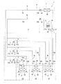
図1は、本発明の一実施形態にかかる空気調和装置1の概略構成図である。空気調和装置1は、主として、室外ユニット2と複数(ここでは、3つ)の室内ユニット3、4、5とが第1及び第2冷媒連絡管9、10を介して接続されることによって構成された蒸気圧縮式の冷媒回路11を有しており、例えば、建物(ここでは、建物S)内の複数(ここでは、3つ)の空調空間S1、S2、S3の冷房や除湿に使用されるものである。本実施形態において、冷媒回路11には、冷媒として二酸化炭素が封入されている。
(1) Embodiment FIG. 1 is a schematic configuration diagram of an air-conditioning apparatus 1 according to an embodiment of the present invention. The air conditioner 1 is mainly configured by connecting an outdoor unit 2 and a plurality of (here, three) indoor units 3, 4, and 5 via first and second refrigerant communication pipes 9 and 10. The vapor compression refrigerant circuit 11 is used, for example, for cooling or dehumidifying a plurality (here, three) of air-conditioned spaces S1, S2, S3 in a building (here, building S). Is. In the present embodiment, the refrigerant circuit 11 is filled with carbon dioxide as a refrigerant.

<室内ユニット>
次に、室内ユニット3、4、5の構成について説明する。
<Indoor unit>
Next, the configuration of the indoor units 3, 4, and 5 will be described.

室内ユニット3は、空調空間S1の天井や壁等に設置されており、主として、室内冷媒管32と、室内冷媒管32に設けられた室内熱交換器33とを有している。室内冷媒管32の一端には、第1連絡管用接続ポート32aが設けられており、室内冷媒管32の他端には、第2連絡管用接続ポート32bが設けられている。本実施形態において、室内熱交換器33は、冷媒と空調空間S1内の空気との熱交換を行うための熱交換器である。また、室内ユニット3には、室内熱交換器33の第1連絡管用接続ポート32a側の冷媒の温度を検出する第1室内側冷媒温度センサ34と、室内熱交換器33の第2連絡管用接続ポート32b側の冷媒の温度を検出する第2室内側冷媒温度センサ35とが設けられている。本実施形態において、室内側冷媒温度センサ34、35は、サーミスタからなる。さらに、室内ユニット3には、室内ユニット3を構成する各部の動作を制御する室内側制御部36が設けられている。この室内側制御部36は、室内ユニット3の制御を行うために設けられたマイクロコンピュータやメモリ等を有しており、室外ユニット2との間で制御信号等のやりとりを行ったり、後述の膨張ユニット6の室内膨張弁31に対して開度制御のための制御信号を送ることができるようになっている。   The indoor unit 3 is installed on the ceiling or wall of the air-conditioned space S1, and mainly includes an indoor refrigerant pipe 32 and an indoor heat exchanger 33 provided in the indoor refrigerant pipe 32. A first connecting pipe connection port 32 a is provided at one end of the indoor refrigerant pipe 32, and a second connecting pipe connection port 32 b is provided at the other end of the indoor refrigerant pipe 32. In this embodiment, the indoor heat exchanger 33 is a heat exchanger for performing heat exchange between the refrigerant and the air in the air-conditioned space S1. Further, the indoor unit 3 includes a first indoor-side refrigerant temperature sensor 34 that detects the temperature of the refrigerant on the first communication pipe connection port 32 a side of the indoor heat exchanger 33, and a second communication pipe connection of the indoor heat exchanger 33. A second indoor-side refrigerant temperature sensor 35 that detects the temperature of the refrigerant on the port 32b side is provided. In the present embodiment, the indoor refrigerant temperature sensors 34 and 35 are thermistors. Further, the indoor unit 3 is provided with an indoor side control unit 36 that controls the operation of each part constituting the indoor unit 3. The indoor side control unit 36 includes a microcomputer, a memory, and the like provided for controlling the indoor unit 3, exchanges control signals and the like with the outdoor unit 2, and expands as described later. A control signal for opening degree control can be sent to the indoor expansion valve 31 of the unit 6.

また、室内ユニット4は、空調空間S2の天井や壁等に設置されており、主として、室内冷媒管42と、室内冷媒管42に設けられた室内熱交換器43とを有している。室内冷媒管42の一端には、第1連絡管用接続ポート42aが設けられており、室内冷媒管42の他端には、第2連絡管用接続ポート42bが設けられている。本実施形態において、室内熱交換器43は、冷媒と空調空間S2内の空気との熱交換を行うための熱交換器である。また、室内ユニット4には、室内熱交換器43の第1連絡管用接続ポート42a側の冷媒の温度を検出する第1室内側冷媒温度センサ44と、室内熱交換器43の第2連絡管用接続ポート42b側の冷媒の温度を検出する第2室内側冷媒温度センサ45とが設けられている。本実施形態において、室内側冷媒温度センサ44、45は、サーミスタからなる。さらに、室内ユニット4には、室内ユニット4を構成する各部の動作を制御する室内側制御部46が設けられている。この室内側制御部46は、室内ユニット4の制御を行うために設けられたマイクロコンピュータやメモリ等を有しており、室外ユニット2との間で制御信号等のやりとりを行ったり、後述の膨張ユニット7の室内膨張弁41に対して開度制御のための制御信号を送ることができるようになっている。   The indoor unit 4 is installed on the ceiling or wall of the air-conditioned space S2, and mainly includes an indoor refrigerant pipe 42 and an indoor heat exchanger 43 provided in the indoor refrigerant pipe 42. A first connecting pipe connection port 42 a is provided at one end of the indoor refrigerant pipe 42, and a second connecting pipe connection port 42 b is provided at the other end of the indoor refrigerant pipe 42. In this embodiment, the indoor heat exchanger 43 is a heat exchanger for performing heat exchange between the refrigerant and the air in the air-conditioned space S2. Further, the indoor unit 4 includes a first indoor-side refrigerant temperature sensor 44 that detects the temperature of the refrigerant on the first communication pipe connection port 42 a side of the indoor heat exchanger 43, and a second communication pipe connection of the indoor heat exchanger 43. A second indoor side refrigerant temperature sensor 45 that detects the temperature of the refrigerant on the port 42b side is provided. In the present embodiment, the indoor refrigerant temperature sensors 44 and 45 are thermistors. Further, the indoor unit 4 is provided with an indoor side control unit 46 that controls the operation of each part constituting the indoor unit 4. The indoor side control unit 46 includes a microcomputer, a memory, and the like provided for controlling the indoor unit 4, exchanges control signals and the like with the outdoor unit 2, and expands as described later. A control signal for opening degree control can be sent to the indoor expansion valve 41 of the unit 7.

また、室内ユニット5は、空調空間S3の天井や壁等に設置されており、主として、室内冷媒管52と、室内冷媒管52に設けられた室内熱交換器53とを有している。室内冷媒管52の一端には、第1連絡管用接続ポート52aが設けられており、室内冷媒管52の他端には、第2連絡管用接続ポート52bが設けられている。本実施形態において、室内熱交換器53は、冷媒と空調空間S3内の空気との熱交換を行うための熱交換器である。また、室内ユニット5には、室内熱交換器53の第1連絡管用接続ポート52a側の冷媒の温度を検出する第1室内側冷媒温度センサ54と、室内熱交換器53の第2連絡管用接続ポート42b側の冷媒の温度を検出する第2室内側冷媒温度センサ55とが設けられている。本実施形態において、室内側冷媒温度センサ54、55は、サーミスタからなる。さらに、室内ユニット4には、室内ユニット5を構成する各部の動作を制御する室内側制御部46が設けられている。この室内側制御部56は、室内ユニット4の制御を行うために設けられたマイクロコンピュータやメモリ等を有しており、室外ユニット2との間で制御信号等のやりとりを行ったり、後述の膨張ユニット8の室内膨張弁51に対して開度制御のための制御信号を送ることができるようになっている。   The indoor unit 5 is installed on the ceiling or wall of the air-conditioned space S3, and mainly includes an indoor refrigerant pipe 52 and an indoor heat exchanger 53 provided in the indoor refrigerant pipe 52. A first connecting pipe connection port 52 a is provided at one end of the indoor refrigerant pipe 52, and a second connecting pipe connection port 52 b is provided at the other end of the indoor refrigerant pipe 52. In the present embodiment, the indoor heat exchanger 53 is a heat exchanger for performing heat exchange between the refrigerant and the air in the air-conditioned space S3. The indoor unit 5 includes a first indoor side refrigerant temperature sensor 54 that detects the temperature of the refrigerant on the first connection pipe connection port 52 a side of the indoor heat exchanger 53, and a second connection pipe connection of the indoor heat exchanger 53. A second indoor side refrigerant temperature sensor 55 that detects the temperature of the refrigerant on the port 42b side is provided. In the present embodiment, the indoor refrigerant temperature sensors 54 and 55 are thermistors. Further, the indoor unit 4 is provided with an indoor side control unit 46 that controls the operation of each unit constituting the indoor unit 5. The indoor side control unit 56 includes a microcomputer, a memory, and the like provided for controlling the indoor unit 4, exchanges control signals and the like with the outdoor unit 2, and expands as described later. A control signal for opening degree control can be sent to the indoor expansion valve 51 of the unit 8.

<室外ユニット>
次に、室外ユニット2の構成について説明する。
<Outdoor unit>
Next, the configuration of the outdoor unit 2 will be described.

室外ユニット2は、建物Sの屋上等に設置されており、主として、圧縮機21と、室外熱交換器22と、第1閉鎖弁23と、第2閉鎖弁24とを有している。   The outdoor unit 2 is installed on the rooftop of the building S or the like, and mainly includes a compressor 21, an outdoor heat exchanger 22, a first closing valve 23, and a second closing valve 24.

圧縮機21は、本実施形態において、モータ21aによって駆動される密閉式圧縮機である。尚、本実施形態において、圧縮機21は、1台のみであるが、これに限定されず、室内ユニットの接続台数等に応じて、2台以上の圧縮機が並列に接続されていてもよい。   In this embodiment, the compressor 21 is a hermetic compressor driven by a motor 21a. In the present embodiment, the number of the compressors 21 is only one. However, the present invention is not limited to this, and two or more compressors may be connected in parallel according to the number of indoor units connected. .

本実施形態において、室外熱交換器22は、冷媒と熱源としての水や空気との熱交換を行うための熱交換器である、室外熱交換器22の一端は、圧縮機21の吐出側に接続され、室外熱交換器22の他端は、第1閉鎖弁23に接続されている。   In this embodiment, the outdoor heat exchanger 22 is a heat exchanger for performing heat exchange between the refrigerant and water or air as a heat source. One end of the outdoor heat exchanger 22 is connected to the discharge side of the compressor 21. The other end of the outdoor heat exchanger 22 is connected to the first closing valve 23.

第1閉鎖弁23は、外部の機器・配管(具体的には、第1冷媒連絡管9)との接続ポート23aに設けられた弁である。また、第2閉鎖弁24は、外部の機器・配管(具体的には、第2冷媒連絡管10)との接続ポート24aに設けられた弁である。第1閉鎖弁23は、室外熱交換器22に接続されている。第2閉鎖弁24は、圧縮機21の吸入側に接続されている。   The first closing valve 23 is a valve provided at a connection port 23a with an external device / pipe (specifically, the first refrigerant communication pipe 9). Moreover, the 2nd closing valve 24 is a valve provided in the connection port 24a with an external apparatus and piping (specifically 2nd refrigerant | coolant communication pipe | tube 10). The first closing valve 23 is connected to the outdoor heat exchanger 22. The second closing valve 24 is connected to the suction side of the compressor 21.

また、室外ユニット2には、圧縮機21の吸入圧力を検出する吸入圧力センサ25と、圧縮機21の吐出圧力を検出する吐出圧力センサ26とが設けられている。さらに、室外ユニット2は、室外ユニット2を構成する各部の動作を制御する室外側制御部27を有している。この室外側制御部27は、室外ユニット2の制御を行うために設けられたマイクロコンピュータやメモリ等を有しており、室内ユニット3、4、5の室内側制御部36、46、56との間で制御信号等のやりとりを行うことができるようになっている。   The outdoor unit 2 is provided with a suction pressure sensor 25 that detects the suction pressure of the compressor 21 and a discharge pressure sensor 26 that detects the discharge pressure of the compressor 21. Furthermore, the outdoor unit 2 has an outdoor side control unit 27 that controls the operation of each unit constituting the outdoor unit 2. The outdoor control unit 27 includes a microcomputer, a memory, and the like provided to control the outdoor unit 2, and is connected to the indoor side control units 36, 46, 56 of the indoor units 3, 4, 5. Control signals and the like can be exchanged between them.

<冷媒連絡管>
冷媒連絡管9、10は、空気調和装置1を建物Sに設置する際に、現地にて施工される冷媒管であり、室外ユニット2と複数の室内ユニット3、4、5とを接続している。第1冷媒連絡管9は、建物Sの天井裏や壁裏等に設置されており、室外ユニット2の第1閉鎖弁23の接続ポート23aから室内ユニット3、4、5寄りの位置まで延びる第1合流連絡管9aと、第1合流連絡管9aから各室内ユニット3、4、5に分岐する第1分岐連絡管9b、9c、9dとを有している。第1分岐連絡管9bは、室内ユニット3の第1連絡管用接続ポート32aに接続されており、第1分岐連絡管9cは、室内ユニット4の第1連絡管用接続ポート42aに接続されており、第1分岐連絡管9dは、室内ユニット5の第1連絡管用接続ポート52aに接続されている。また、第2冷媒連絡管10は、室外ユニット2の第2閉鎖弁24の接続ポート24aから建物Sの天井裏や壁裏を通じて室内ユニット3、4、5寄りの位置まで延びる第2合流連絡管10aと、第2合流連絡管10aから各室内ユニット3、4、5に分岐する第2分岐連絡管10b、10c、10dとを有している。第2分岐連絡管10bは、室内ユニット3の第2連絡管用接続ポート32bに接続されており、第2分岐連絡管10cは、室内ユニット4の第2連絡管用接続ポート42bに接続されており、第2分岐連絡管10dは、室内ユニット5の第2連絡管用接続ポート52bに接続されている。そして、本実施形態において、第1冷媒連絡管9には、膨張ユニット6、7、8が設けられている。
<Refrigerant communication pipe>
Refrigerant communication pipes 9 and 10 are refrigerant pipes constructed on site when the air conditioner 1 is installed in the building S, and connect the outdoor unit 2 and the plurality of indoor units 3, 4, and 5. Yes. The first refrigerant communication pipe 9 is installed on the ceiling or the back of the wall of the building S, and extends from the connection port 23a of the first closing valve 23 of the outdoor unit 2 to a position near the indoor units 3, 4, and 5. It has 1 merging connecting pipe 9a and first branch connecting pipes 9b, 9c, 9d that branch from the first merging connecting pipe 9a to the indoor units 3, 4, 5 respectively. The first branch connecting pipe 9b is connected to the first connecting pipe connecting port 32a of the indoor unit 3, and the first branch connecting pipe 9c is connected to the first connecting pipe connecting port 42a of the indoor unit 4, The first branch connecting pipe 9 d is connected to the first connecting pipe connection port 52 a of the indoor unit 5. The second refrigerant communication pipe 10 extends from the connection port 24a of the second closing valve 24 of the outdoor unit 2 to the position near the indoor units 3, 4 and 5 through the ceiling and the back of the building S. 10a and second branch connecting pipes 10b, 10c, and 10d that branch from the second joining connecting pipe 10a to the indoor units 3, 4, and 5. The second branch connecting pipe 10b is connected to the second connecting pipe connecting port 32b of the indoor unit 3, and the second branch connecting pipe 10c is connected to the second connecting pipe connecting port 42b of the indoor unit 4, The second branch connecting pipe 10 d is connected to the second connecting pipe connection port 52 b of the indoor unit 5. In the present embodiment, the first refrigerant communication pipe 9 is provided with expansion units 6, 7, and 8.

<膨張ユニット>
次に、膨張ユニット6、7、8の構成について説明する。
<Expansion unit>
Next, the configuration of the expansion units 6, 7, and 8 will be described.

膨張ユニット6は、建物Sの天井裏や壁裏等に設置されており、主として、第1冷媒管61と、室内膨張弁31とを有している。第1冷媒管61の一端には、第1冷媒連絡管9の室外ユニット2側の部分(ここでは、第1分岐連絡管9bの室外ユニット2側の部分)に接続される第1室外ユニット用接続ポート61aが設けられており、第1冷媒管61の他端には、第1冷媒連絡管9の室内ユニット3側の部分(ここでは、第1分岐連絡管9bの室内ユニット3側の部分)に接続される第1室内ユニット用接続ポート61bが設けられている。本実施形態において、室内膨張弁31は、室内ユニット3を流れる冷媒の流量を制御するための電動膨張弁である。そして、この室内膨張弁31は、室内ユニット3からの指令(すなわち、室内側制御部36からの制御信号)によって開度制御が行われるようになっている。   The expansion unit 6 is installed on the ceiling, the wall, or the like of the building S, and mainly includes the first refrigerant pipe 61 and the indoor expansion valve 31. One end of the first refrigerant pipe 61 is for a first outdoor unit connected to a part of the first refrigerant communication pipe 9 on the outdoor unit 2 side (here, a part of the first branch communication pipe 9b on the outdoor unit 2 side). A connection port 61a is provided, and at the other end of the first refrigerant pipe 61, a part of the first refrigerant communication pipe 9 on the indoor unit 3 side (here, a part of the first branch communication pipe 9b on the indoor unit 3 side). ) Is connected to the first indoor unit connection port 61b. In the present embodiment, the indoor expansion valve 31 is an electric expansion valve for controlling the flow rate of the refrigerant flowing through the indoor unit 3. The opening of the indoor expansion valve 31 is controlled by a command from the indoor unit 3 (that is, a control signal from the indoor side control unit 36).

膨張ユニット7は、建物Sの天井裏や壁裏等に設置されており、主として、第1冷媒管71と、室内膨張弁41とを有している。第1冷媒管71の一端には、第1冷媒連絡管9の室外ユニット2側の部分(ここでは、第1分岐連絡管9cの室外ユニット2側の部分)に接続される第1室外ユニット用接続ポート71aが設けられており、第1冷媒管71の他端には、第1冷媒連絡管9の室内ユニット4側の部分(ここでは、第1分岐連絡管9cの室内ユニット4側の部分)に接続される第1室内ユニット用接続ポート71bが設けられている。本実施形態において、室内膨張弁41は、室内ユニット4を流れる冷媒の流量を制御するための電動膨張弁である。そして、この室内膨張弁41は、室内ユニット4からの指令(すなわち、室内側制御部46からの制御信号)によって開度制御が行われるようになっている。   The expansion unit 7 is installed on the ceiling, the wall, or the like of the building S, and mainly includes a first refrigerant pipe 71 and an indoor expansion valve 41. One end of the first refrigerant pipe 71 is for a first outdoor unit connected to a part of the first refrigerant communication pipe 9 on the outdoor unit 2 side (here, a part of the first branch communication pipe 9c on the outdoor unit 2 side). A connection port 71a is provided, and at the other end of the first refrigerant pipe 71, a part of the first refrigerant communication pipe 9 on the indoor unit 4 side (here, a part of the first branch communication pipe 9c on the indoor unit 4 side). ) Is connected to the first indoor unit connection port 71b. In the present embodiment, the indoor expansion valve 41 is an electric expansion valve for controlling the flow rate of the refrigerant flowing through the indoor unit 4. The opening of the indoor expansion valve 41 is controlled by a command from the indoor unit 4 (that is, a control signal from the indoor side control unit 46).

膨張ユニット8は、建物Sの天井裏や壁裏等に設置されており、主として、第1冷媒管81と、室内膨張弁51とを有している。第1冷媒管81の一端には、第1冷媒連絡管9の室外ユニット2側の部分(ここでは、第1分岐連絡管9dの室外ユニット2側の部分)に接続される第1室外ユニット用接続ポート81aが設けられており、第1冷媒管81の他端には、第1冷媒連絡管9の室内ユニット5側の部分(ここでは、第1分岐連絡管9dの室内ユニット5側の部分)に接続される第1室内ユニット用接続ポート81bが設けられている。本実施形態において、室内膨張弁51は、室内ユニット5を流れる冷媒の流量を制御するための電動膨張弁である。そして、この室内膨張弁51は、室内ユニット5からの指令(すなわち、室内側制御部56からの制御信号)によって開度制御が行われるようになっている。   The expansion unit 8 is installed on the back of the ceiling or the wall of the building S, and mainly includes a first refrigerant pipe 81 and an indoor expansion valve 51. One end of the first refrigerant pipe 81 is connected to a part on the outdoor unit 2 side of the first refrigerant communication pipe 9 (here, a part on the outdoor unit 2 side of the first branch communication pipe 9d). A connection port 81a is provided, and at the other end of the first refrigerant pipe 81, a part of the first refrigerant communication pipe 9 on the indoor unit 5 side (here, a part of the first branch communication pipe 9d on the indoor unit 5 side). ) Is connected to the first indoor unit connection port 81b. In the present embodiment, the indoor expansion valve 51 is an electric expansion valve for controlling the flow rate of the refrigerant flowing through the indoor unit 5. The indoor expansion valve 51 is controlled in opening degree by a command from the indoor unit 5 (that is, a control signal from the indoor side control unit 56).

このように、本実施形態の空気調和装置1では、従来のような各室内ユニット3、4、5に各室内ユニット3、4、5を流れる冷媒の流量を制御するための室内膨張弁31、41、51がそれぞれ設けられた構成とは異なり、室内膨張弁31、41、51が室内ユニット3、4、5とは別の膨張ユニット6、7、8として設けられるとともに、室内ユニット3、4、5からの指令によって膨張ユニット6、7、8の室内膨張弁31、41、51の開度制御を行うように構成されている。   Thus, in the air conditioning apparatus 1 of the present embodiment, the indoor expansion valve 31 for controlling the flow rate of the refrigerant flowing through the indoor units 3, 4, 5 to the indoor units 3, 4, 5 as in the prior art, Unlike the configuration in which 41 and 51 are provided, the indoor expansion valves 31, 41 and 51 are provided as expansion units 6, 7 and 8, which are different from the indoor units 3, 4 and 5, and 5, the opening degree control of the indoor expansion valves 31, 41, 51 of the expansion units 6, 7, 8 is performed.

<空気調和装置の動作及び特徴>
次に、本実施形態の空気調和装置1の通常運転(冷房や除湿)時の動作について、複数(ここでは、3つ)の室内ユニット3、4、5のすべてを運転する場合を例にして説明する。
<Operation and features of air conditioner>
Next, with regard to the operation during normal operation (cooling and dehumidification) of the air conditioner 1 of the present embodiment, a case where all of the plurality (here, three) of indoor units 3, 4, 5 are operated is taken as an example. explain.

まず、低圧の冷媒は、室外ユニット2に設けられた圧縮機21に吸入されて圧縮されて高圧の冷媒となる。この圧縮機21によって圧縮された高圧の冷媒は、室外熱交換器22に送られて、熱源としての水や空気と熱交換を行って放熱する。この室外熱交換器22において放熱した高圧の冷媒は、第1閉鎖弁23を通じて第1冷媒連絡管9の第1合流連絡管9aに送られる。   First, the low-pressure refrigerant is sucked into the compressor 21 provided in the outdoor unit 2 and compressed to become a high-pressure refrigerant. The high-pressure refrigerant compressed by the compressor 21 is sent to the outdoor heat exchanger 22 to dissipate heat by exchanging heat with water or air as a heat source. The high-pressure refrigerant that has dissipated heat in the outdoor heat exchanger 22 is sent to the first merging communication pipe 9 a of the first refrigerant communication pipe 9 through the first closing valve 23.

そして、この第1合流連絡管9aに送られた高圧の冷媒は、複数(ここでは、3つ)の第1分岐連絡管9b、9c、9dに分岐される。   The high-pressure refrigerant sent to the first junction connecting pipe 9a is branched into a plurality (here, three) of first branch connecting pipes 9b, 9c, and 9d.

そして、第1分岐連絡管9bに分岐された高圧の冷媒は、第1分岐連絡管9bの室外ユニット2側の部分を通じて膨張ユニット6に流入して、膨張ユニット6の第1冷媒管61に設けられた室内膨張弁31によって減圧されて低圧の気液二相状態の冷媒になる。この室内膨張弁31によって減圧された低圧の気液二相状態の冷媒は、第1冷媒管61を通じて第1冷媒連絡管9の第1分岐連絡管9bの室内ユニット3側の部分に送られる。この第1分岐連絡管9bの室内ユニット3側の部分に送られた低圧の気液二相状態の冷媒は、室内ユニット3に流入して、室内ユニット3の室内冷媒管32に設けられた室内熱交換器33において、空調空間S1内の空気と熱交換を行って蒸発する。この室内熱交換器33において蒸発した低圧の冷媒は、室内冷媒管32を通じて第2冷媒連絡管10の第2分岐連絡管10bの室内ユニット3側の部分に送られる。ここで、室内膨張弁31は、室内熱交換器33の出口における冷媒の過熱度が所定値になるように開度調節されるようになっている。本実施形態において、室内熱交換器33の出口における冷媒の過熱度は、第2室内側冷媒温度センサ35によって検出される室内熱交換器33の第2連絡管用接続ポート32b側の冷媒の温度から第1室内側冷媒温度センサ34によって検出される室内熱交換器33の第1連絡管用接続ポート32a側の冷媒の温度を差し引くか、又は、吸入圧力センサ25により検出される圧縮機21の吸入圧力を冷媒の飽和温度に換算し、第2室内側冷媒温度センサ35によって検出される室内熱交換器33の第2連絡管用接続ポート32b側の冷媒の温度から圧縮機21の吸入圧力を換算して得られる冷媒の飽和温度を差し引くことによって得られる。   Then, the high-pressure refrigerant branched into the first branch connecting pipe 9b flows into the expansion unit 6 through the portion of the first branch connecting pipe 9b on the outdoor unit 2 side, and is provided in the first refrigerant pipe 61 of the expansion unit 6. The pressure is reduced by the indoor expansion valve 31 and becomes a low-pressure gas-liquid two-phase refrigerant. The low-pressure gas-liquid two-phase refrigerant decompressed by the indoor expansion valve 31 is sent to the indoor unit 3 side portion of the first branch communication pipe 9b of the first refrigerant communication pipe 9 through the first refrigerant pipe 61. The low-pressure gas-liquid two-phase refrigerant sent to the portion of the first branch connecting pipe 9b on the indoor unit 3 side flows into the indoor unit 3 and is provided in the indoor refrigerant tube 32 of the indoor unit 3. The heat exchanger 33 evaporates by exchanging heat with the air in the air-conditioned space S1. The low-pressure refrigerant evaporated in the indoor heat exchanger 33 is sent through the indoor refrigerant pipe 32 to the portion of the second branch communication pipe 10b of the second refrigerant communication pipe 10 on the indoor unit 3 side. Here, the opening degree of the indoor expansion valve 31 is adjusted so that the degree of superheat of the refrigerant at the outlet of the indoor heat exchanger 33 becomes a predetermined value. In the present embodiment, the degree of superheat of the refrigerant at the outlet of the indoor heat exchanger 33 is determined from the temperature of the refrigerant on the second connecting pipe connection port 32b side of the indoor heat exchanger 33 detected by the second indoor-side refrigerant temperature sensor 35. The suction pressure of the compressor 21 detected by the suction pressure sensor 25 is subtracted from the temperature of the refrigerant on the first connecting pipe connection port 32a side of the indoor heat exchanger 33 detected by the first indoor side refrigerant temperature sensor 34. Is converted into the saturation temperature of the refrigerant, and the suction pressure of the compressor 21 is converted from the refrigerant temperature on the second connecting pipe connection port 32b side of the indoor heat exchanger 33 detected by the second indoor-side refrigerant temperature sensor 35. It is obtained by subtracting the saturation temperature of the resulting refrigerant.

また、第1分岐連絡管9cに分岐された高圧の冷媒は、膨張ユニット7に流入して、第1冷媒管71に設けられた室内膨張弁41によって減圧されて低圧の気液二相状態の冷媒になる。この室内膨張弁41によって減圧された低圧の気液二相状態の冷媒は、第1冷媒管71を通じて第1冷媒連絡管9の第1分岐連絡管9cの室内ユニット4側の部分に送られる。この第1分岐連絡管9cの室内ユニット4側の部分に送られた低圧の気液二相状態の冷媒は、室内ユニット4に流入して、室内ユニット4の室内冷媒管42に設けられた室内熱交換器43において、空調空間S2内の空気と熱交換を行って蒸発する。この室内熱交換器43において蒸発した低圧の冷媒は、室内冷媒管42を通じて第2冷媒連絡管10の第2分岐連絡管10cの室内ユニット4側の部分に送られる。ここで、室内膨張弁41は、室内熱交換器43の出口における冷媒の過熱度が所定値になるように開度調節されるようになっている。本実施形態において、室内熱交換器43の出口における冷媒の過熱度は、第2室内側冷媒温度センサ45によって検出される室内熱交換器43の第2連絡管用接続ポート42b側の冷媒の温度から第1室内側冷媒温度センサ44によって検出される室内熱交換器43の第1連絡管用接続ポート42a側の冷媒の温度を差し引くか、又は、吸入圧力センサ25により検出される圧縮機21の吸入圧力を冷媒の飽和温度に換算し、第2室内側冷媒温度センサ45によって検出される室内熱交換器43の第2連絡管用接続ポート42b側の冷媒の温度から圧縮機21の吸入圧力を換算して得られる冷媒の飽和温度を差し引くことによって得られる。   Further, the high-pressure refrigerant branched into the first branch connecting pipe 9c flows into the expansion unit 7 and is decompressed by the indoor expansion valve 41 provided in the first refrigerant pipe 71 to be in a low-pressure gas-liquid two-phase state. Become a refrigerant. The low-pressure gas-liquid two-phase refrigerant decompressed by the indoor expansion valve 41 is sent through the first refrigerant pipe 71 to the portion on the indoor unit 4 side of the first branch communication pipe 9c of the first refrigerant communication pipe 9. The low-pressure gas-liquid two-phase refrigerant sent to the portion of the first branch connecting pipe 9 c on the indoor unit 4 side flows into the indoor unit 4 and is provided in the indoor refrigerant pipe 42 of the indoor unit 4. The heat exchanger 43 evaporates by exchanging heat with the air in the air-conditioned space S2. The low-pressure refrigerant evaporated in the indoor heat exchanger 43 is sent to the indoor unit 4 side portion of the second branch communication pipe 10c of the second refrigerant communication pipe 10 through the indoor refrigerant pipe 42. Here, the opening degree of the indoor expansion valve 41 is adjusted so that the degree of superheat of the refrigerant at the outlet of the indoor heat exchanger 43 becomes a predetermined value. In the present embodiment, the degree of superheat of the refrigerant at the outlet of the indoor heat exchanger 43 is determined from the temperature of the refrigerant on the second connecting pipe connection port 42 b side of the indoor heat exchanger 43 detected by the second indoor side refrigerant temperature sensor 45. The suction pressure of the compressor 21 detected by the suction pressure sensor 25 is subtracted from the temperature of the refrigerant on the first communication pipe connection port 42 a side of the indoor heat exchanger 43 detected by the first indoor side refrigerant temperature sensor 44. Is converted into the refrigerant saturation temperature, and the suction pressure of the compressor 21 is converted from the refrigerant temperature on the second connecting pipe connection port 42b side of the indoor heat exchanger 43 detected by the second indoor refrigerant temperature sensor 45. It is obtained by subtracting the saturation temperature of the resulting refrigerant.

また、第1分岐連絡管9dに分岐された高圧の冷媒は、膨張ユニット8に流入して、第1冷媒管81に設けられた室内膨張弁51によって減圧されて低圧の気液二相状態の冷媒になる。この室内膨張弁51によって減圧された低圧の気液二相状態の冷媒は、第1冷媒管81を通じて第1冷媒連絡管9の第1分岐連絡管9dの室内ユニット5側の部分に送られる。この第1分岐連絡管9dの室内ユニット5側の部分に送られた低圧の気液二相状態の冷媒は、室内ユニット5に流入して、室内ユニット5の室内冷媒管52に設けられた室内熱交換器53において、空調空間S3内の空気と熱交換を行って蒸発する。この室内熱交換器53において蒸発した低圧の冷媒は、室内冷媒管52を通じて第2冷媒連絡管10の第2分岐連絡管10dの室内ユニット5側の部分に送られる。ここで、室内膨張弁51は、室内熱交換器53の出口における冷媒の過熱度が所定値になるように開度調節されるようになっている。本実施形態において、室内熱交換器53の出口における冷媒の過熱度は、第2室内側冷媒温度センサ55によって検出される室内熱交換器53の第2連絡管用接続ポート52b側の冷媒の温度から第1室内側冷媒温度センサ54によって検出される室内熱交換器53の第1連絡管用接続ポート52a側の冷媒の温度を差し引くか、又は、吸入圧力センサ25により検出される圧縮機21の吸入圧力を冷媒の飽和温度に換算し、第2室内側冷媒温度センサ55によって検出される室内熱交換器53の第2連絡管用接続ポート52b側の冷媒の温度から圧縮機21の吸入圧力を換算して得られる冷媒の飽和温度を差し引くことによって得られる。   The high-pressure refrigerant branched into the first branch connecting pipe 9d flows into the expansion unit 8 and is decompressed by the indoor expansion valve 51 provided in the first refrigerant pipe 81, so that the low-pressure gas-liquid two-phase state is obtained. Become a refrigerant. The low-pressure gas-liquid two-phase refrigerant decompressed by the indoor expansion valve 51 is sent through the first refrigerant pipe 81 to the portion of the first branch communication pipe 9d of the first refrigerant communication pipe 9 on the indoor unit 5 side. The low-pressure gas-liquid two-phase refrigerant sent to the portion of the first branch connecting pipe 9d on the indoor unit 5 side flows into the indoor unit 5 and is provided in the indoor refrigerant pipe 52 of the indoor unit 5. The heat exchanger 53 evaporates by exchanging heat with the air in the air-conditioned space S3. The low-pressure refrigerant evaporated in the indoor heat exchanger 53 is sent to the indoor unit 5 side portion of the second branch communication pipe 10d of the second refrigerant communication pipe 10 through the indoor refrigerant pipe 52. Here, the opening of the indoor expansion valve 51 is adjusted so that the degree of superheat of the refrigerant at the outlet of the indoor heat exchanger 53 becomes a predetermined value. In the present embodiment, the degree of superheat of the refrigerant at the outlet of the indoor heat exchanger 53 is determined from the temperature of the refrigerant on the second connecting pipe connection port 52 b side of the indoor heat exchanger 53 detected by the second indoor side refrigerant temperature sensor 55. The refrigerant pressure on the first connecting pipe connection port 52a side of the indoor heat exchanger 53 detected by the first indoor refrigerant temperature sensor 54 is subtracted, or the suction pressure of the compressor 21 detected by the suction pressure sensor 25 Is converted into the refrigerant saturation temperature, and the suction pressure of the compressor 21 is converted from the refrigerant temperature on the second connecting pipe connection port 52b side of the indoor heat exchanger 53 detected by the second indoor-side refrigerant temperature sensor 55. It is obtained by subtracting the saturation temperature of the resulting refrigerant.

そして、第2分岐連絡管10bの室内ユニット3側の部分に送られた低圧の冷媒と第2分岐連絡管10cの室内ユニット4側の部分に送られた低圧の冷媒と第2分岐連絡管10dの室内ユニット5側の部分に送られた低圧の冷媒とは、第2冷媒連絡管10の第2合流連絡管10aに合流する。   The low-pressure refrigerant sent to the portion of the second branch connecting pipe 10b on the indoor unit 3 side, the low-pressure refrigerant sent to the portion of the second branch connecting pipe 10c on the indoor unit 4 side, and the second branch connecting pipe 10d. The low-pressure refrigerant sent to the indoor unit 5 side portion joins the second merging communication pipe 10 a of the second refrigerant communication pipe 10.

そして、第2合流連絡管10aに合流した低圧の冷媒は、室外ユニット2に流入し、第2閉鎖弁24を通じて圧縮機21に送られる。このようにして、本実施形態の空気調和装置1の通常運転が行われる。   Then, the low-pressure refrigerant joined to the second joining communication pipe 10 a flows into the outdoor unit 2 and is sent to the compressor 21 through the second closing valve 24. In this manner, the normal operation of the air conditioner 1 of the present embodiment is performed.

このような本実施形態の空気調和装置1では、各室内ユニット3、4、5を流れる冷媒の流量を制御するための電動膨張弁としての室内膨張弁31、41、51を室内ユニット3、4、5とは別の膨張ユニット6、7、8として設けているため、室内膨張弁31、41、51を室内ユニット3、4、5が配置された空調空間S1、S2、S3から遠ざけることができ、これにより、冷媒が室内膨張弁31、41、51を通過する際の音の問題を生じにくくすることができる。しかも、室内膨張弁31、41、51を室内ユニット3、4、5とは別の膨張ユニット6、7、8として設けるにあたり、室内ユニット3、4、5内に室内膨張弁31、41、51を設けた場合と同様に、各室内ユニット3、4、5に設けられた温度センサ34、35、44、45、54、55等を用いて、室内ユニット3、4、5からの指令によって室内膨張弁31、41、51の開度制御(ここでは、室内熱交換器33、43、53の出口における冷媒の過熱度を所定値で一定にする制御)を行うように構成しているため、室内膨張弁31、41、51を有する室内ユニット3、4、5の制御構成をほとんど変更することなく使用することができる。したがって、本実施形態の空気調和装置1では、装置全体の制御構成を大幅に変更することなく、冷媒が室内膨張弁31、41、51を通過する際の音の問題を生じにくくすることができる。   In the air conditioner 1 of this embodiment, the indoor expansion valves 31, 41, 51 as electric expansion valves for controlling the flow rate of the refrigerant flowing through the indoor units 3, 4, 5 are connected to the indoor units 3, 4, respectively. 5 is provided as an expansion unit 6, 7, 8 separate from 5, the indoor expansion valves 31, 41, 51 can be moved away from the air-conditioned spaces S1, S2, S3 in which the indoor units 3, 4, 5 are arranged. In this way, it is possible to make it difficult to cause a problem of sound when the refrigerant passes through the indoor expansion valves 31, 41, 51. In addition, when the indoor expansion valves 31, 41, 51 are provided as the expansion units 6, 7, 8 different from the indoor units 3, 4, 5, the indoor expansion valves 31, 41, 51 are provided in the indoor units 3, 4, 5. In the same manner as when the indoor units 3, 4, 5 are provided, the temperature sensors 34, 35, 44, 45, 54, 55, etc. provided in the indoor units 3, 4, 5 Since it is configured to perform opening degree control of the expansion valves 31, 41, 51 (in this case, control for making the degree of superheat of the refrigerant at the outlets of the indoor heat exchangers 33, 43, 53 constant at a predetermined value), The control configuration of the indoor units 3, 4, 5 having the indoor expansion valves 31, 41, 51 can be used with almost no change. Therefore, in the air conditioning apparatus 1 of the present embodiment, the problem of sound when the refrigerant passes through the indoor expansion valves 31, 41, 51 can be made difficult without significantly changing the control configuration of the entire apparatus. .

特に、本実施形態の空気調和装置1のように、冷媒回路11に封入される冷媒として二酸化炭素を使用する場合には、室内膨張弁31、41、51による減圧操作時の圧力落差が大きく、室内膨張弁31、41、51を通過する際の音の問題が生じやすいため、本実施形態の空気調和装置1の構成を採用することによる効果が顕著である。   In particular, when using carbon dioxide as the refrigerant sealed in the refrigerant circuit 11 as in the air conditioner 1 of the present embodiment, the pressure drop during the decompression operation by the indoor expansion valves 31, 41, 51 is large. Since the problem of the sound at the time of passing through the indoor expansion valves 31, 41, 51 is likely to occur, the effect of adopting the configuration of the air conditioning apparatus 1 of the present embodiment is remarkable.

また、本実施形態の空気調和装置1では、膨張ユニット6、7、8が、室内膨張弁31、41、51が設けられた第1冷媒管31、41、51の両端に第1室外ユニット用接続ポート61a、71a、81a及び第1室内ユニット用接続ポート61b、71b、81bを有しているため、膨張ユニット6、7、8を第1冷媒連絡管9(より具体的には、第1分岐連絡管9b、9c、9d)に容易に接続することができる。   In the air conditioner 1 of the present embodiment, the expansion units 6, 7, 8 are for the first outdoor unit at both ends of the first refrigerant pipes 31, 41, 51 provided with the indoor expansion valves 31, 41, 51. Since the connection ports 61a, 71a, 81a and the first indoor unit connection ports 61b, 71b, 81b are provided, the expansion units 6, 7, 8 are connected to the first refrigerant communication pipe 9 (more specifically, the first It can be easily connected to the branch connecting pipes 9b, 9c, 9d).

(2)変形例1
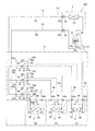
上述の実施形態における空気調和装置1では、室内膨張弁31、41、51を有する膨張ユニット6、7、8が第1冷媒連絡管9に設けられているが、膨張ユニットを、第1冷媒連絡管9とともに室外ユニット2と室内ユニット3、4、5とを接続する第2冷媒連絡管10に設けられるものにしてもよい。以下、本変形例の空気調和装置101について、図2を用いて説明する。ここで、図2は、本変形例にかかる空気調和装置101の概略構成図である。尚、空気調和装置101の構成のうち、上述の実施形態の空気調和装置1の構成と同じ部分については、各部分を表す符号を空気調和装置1の各部と共通にすることで説明を省略し、空気調和装置1と異なる部分を中心に説明する。
(2) Modification 1
In the air conditioner 1 in the above-described embodiment, the expansion units 6, 7, and 8 having the indoor expansion valves 31, 41, and 51 are provided in the first refrigerant communication pipe 9, but the expansion unit is connected to the first refrigerant. It may be provided in the second refrigerant communication pipe 10 that connects the outdoor unit 2 and the indoor units 3, 4, 5 together with the pipe 9. Hereinafter, the air conditioning apparatus 101 of this modification is demonstrated using FIG. Here, FIG. 2 is a schematic configuration diagram of the air-conditioning apparatus 101 according to the present modification. In addition, about the same part as the structure of the air conditioning apparatus 1 of the above-mentioned embodiment among the structures of the air conditioning apparatus 101, description is abbreviate | omitted by making the code | symbol showing each part common with each part of the air conditioning apparatus 1. FIG. The description will focus on the differences from the air conditioner 1.

本変形例の空気調和装置101は、上述の実施形態の空気調和装置1を構成する膨張ユニット6、7、8に代えて、膨張ユニット106、107、108が設けられており、冷媒回路111を構成している。   The air conditioner 101 of this modification is provided with expansion units 106, 107, 108 instead of the expansion units 6, 7, 8 constituting the air conditioner 1 of the above-described embodiment. It is composed.

膨張ユニット106は、上述の実施形態の膨張ユニット6と同様に、建物Sの天井裏や壁裏等に設置されており、主として、第1冷媒管61と、室内膨張弁31と、第2冷媒管62と、第2制御弁63とを有している。第2冷媒管62の一端には、第2冷媒連絡管10の室外ユニット2側の部分(ここでは、第2分岐連絡管10bの室外ユニット2側の部分)に接続される第2室外ユニット用接続ポート62aが設けられており、第2冷媒管62の他端には、第2冷媒連絡管10の室内ユニット3側の部分(ここでは、第2分岐連絡管10bの室内ユニット3側の部分)に接続される第2室内ユニット用接続ポート62bが設けられている。第2制御弁63は、第2冷媒管62内の冷媒の流れを流通/遮断することが可能な弁である。本変形例において、第2制御弁63は、電磁弁である。そして、この第2制御弁63は、室内膨張弁31と同様に、室内ユニット3からの指令(すなわち、室内側制御部36からの制御信号)によって開閉制御が行われるようになっている。   Like the expansion unit 6 of the above-described embodiment, the expansion unit 106 is installed on the ceiling, the back of the wall, or the like of the building S, and mainly includes the first refrigerant pipe 61, the indoor expansion valve 31, and the second refrigerant. It has a pipe 62 and a second control valve 63. One end of the second refrigerant pipe 62 is for a second outdoor unit connected to a part of the second refrigerant communication pipe 10 on the outdoor unit 2 side (here, a part of the second branch communication pipe 10b on the outdoor unit 2 side). A connection port 62a is provided, and at the other end of the second refrigerant pipe 62, a part of the second refrigerant communication pipe 10 on the indoor unit 3 side (here, a part of the second branch communication pipe 10b on the indoor unit 3 side). ) Is connected to the second indoor unit connection port 62b. The second control valve 63 is a valve capable of circulating / blocking the flow of the refrigerant in the second refrigerant pipe 62. In the present modification, the second control valve 63 is an electromagnetic valve. The second control valve 63 is controlled to be opened and closed by a command from the indoor unit 3 (that is, a control signal from the indoor side control unit 36), like the indoor expansion valve 31.

膨張ユニット107は、上述の実施形態の膨張ユニット7と同様に、建物Sの天井裏や壁裏等に設置されており、主として、第1冷媒管71と、室内膨張弁41と、第2冷媒管72と、第2制御弁73とを有している。第2冷媒管72の一端には、第2冷媒連絡管10の室外ユニット2側の部分(ここでは、第2分岐連絡管10cの室外ユニット2側の部分)に接続される第2室外ユニット用接続ポート72aが設けられており、第2冷媒管72の他端には、第2冷媒連絡管10の室内ユニット4側の部分(ここでは、第2分岐連絡管10cの室内ユニット4側の部分)に接続される第2室内ユニット用接続ポート72bが設けられている。第2制御弁73は、第2冷媒管72内の冷媒の流れを流通/遮断することが可能な弁である。本変形例において、第2制御弁73は、電磁弁である。そして、この第2制御弁73は、室内膨張弁41と同様に、室内ユニット4からの指令(すなわち、室内側制御部46からの制御信号)によって開閉制御が行われるようになっている。   Like the expansion unit 7 of the above-described embodiment, the expansion unit 107 is installed on the ceiling, the back of the wall, or the like of the building S, and mainly includes the first refrigerant pipe 71, the indoor expansion valve 41, and the second refrigerant. It has a pipe 72 and a second control valve 73. One end of the second refrigerant pipe 72 is for the second outdoor unit connected to the part on the outdoor unit 2 side of the second refrigerant communication pipe 10 (here, the part on the outdoor unit 2 side of the second branch communication pipe 10c). A connection port 72a is provided, and at the other end of the second refrigerant pipe 72, a part of the second refrigerant communication pipe 10 on the indoor unit 4 side (here, a part of the second branch communication pipe 10c on the indoor unit 4 side). ) Is connected to the second indoor unit connection port 72b. The second control valve 73 is a valve capable of circulating / blocking the flow of the refrigerant in the second refrigerant pipe 72. In the present modification, the second control valve 73 is an electromagnetic valve. The second control valve 73 is controlled to be opened and closed by a command from the indoor unit 4 (that is, a control signal from the indoor-side control unit 46), like the indoor expansion valve 41.

膨張ユニット108は、上述の実施形態の膨張ユニット8と同様に、建物Sの天井裏や壁裏等に設置されており、主として、第1冷媒管81と、室内膨張弁51と、第2冷媒管82と、第2制御弁83とを有している。第2冷媒管82の一端には、第2冷媒連絡管10の室外ユニット2側の部分(ここでは、第2分岐連絡管10dの室外ユニット2側の部分)に接続される第2室外ユニット用接続ポート82aが設けられており、第2冷媒管82の他端には、第2冷媒連絡管10の室内ユニット5側の部分(ここでは、第2分岐連絡管10dの室内ユニット5側の部分)に接続される第2室内ユニット用接続ポート82bが設けられている。第2制御弁83は、第2冷媒管82内の冷媒の流れを流通/遮断することが可能な弁である。本変形例において、第2制御弁83は、電磁弁である。そして、この第2制御弁83は、室内膨張弁51と同様に、室内ユニット5からの指令(すなわち、室内側制御部56からの制御信号)によって開閉制御が行われるようになっている。   Like the expansion unit 8 of the above-described embodiment, the expansion unit 108 is installed on the ceiling, the back of the wall, or the like of the building S, and mainly includes the first refrigerant pipe 81, the indoor expansion valve 51, and the second refrigerant. It has a pipe 82 and a second control valve 83. One end of the second refrigerant pipe 82 is for a second outdoor unit connected to a part of the second refrigerant communication pipe 10 on the outdoor unit 2 side (here, a part of the second branch communication pipe 10d on the outdoor unit 2 side). A connection port 82a is provided, and at the other end of the second refrigerant tube 82, a portion of the second refrigerant communication tube 10 on the indoor unit 5 side (here, a portion of the second branch communication tube 10d on the indoor unit 5 side). ) Is connected to the second indoor unit connection port 82b. The second control valve 83 is a valve capable of circulating / blocking the flow of the refrigerant in the second refrigerant pipe 82. In the present modification, the second control valve 83 is an electromagnetic valve. The second control valve 83 is controlled to be opened and closed by a command from the indoor unit 5 (that is, a control signal from the indoor side control unit 56), like the indoor expansion valve 51.

このように、本変形例の空気調和装置101では、上述の実施形態の空気調和装置1と同様に、室内膨張弁31、41、51が室内ユニット3、4、5とは別の膨張ユニット106、107、108として設けられるとともに、室内ユニット3、4、5からの指令によって膨張ユニット106、107、108の室内膨張弁31、41、51の開度制御を行うように構成されているだけでなく、膨張ユニット106、107、108が、室外ユニット2と室内ユニット3、4、5とを接続する第2冷媒連絡管10にも設けられており、第2制御弁63、73、83によって第2冷媒連絡管10内の冷媒の流れを流通/遮断することが可能になっている。そして、これらの第2制御弁63、73、83についても、室内膨張弁31、41、51と同様に、室内ユニット3、4、5(具体的には、室内側制御部36、46、56)からの指令によって、第2制御弁63、73、83の開閉制御を行うように構成されている。   As described above, in the air conditioner 101 of the present modification, the indoor expansion valves 31, 41, 51 are different from the indoor units 3, 4, 5, as in the air conditioner 1 of the above-described embodiment. , 107, 108, and is configured to control the opening of the indoor expansion valves 31, 41, 51 of the expansion units 106, 107, 108 in response to commands from the indoor units 3, 4, 5 The expansion units 106, 107, and 108 are also provided in the second refrigerant communication pipe 10 that connects the outdoor unit 2 and the indoor units 3, 4, and 5. 2 The refrigerant flow in the refrigerant communication pipe 10 can be circulated / blocked. And about these 2nd control valves 63, 73, 83, similarly to the indoor expansion valves 31, 41, 51, the indoor units 3, 4, 5 (specifically, the indoor side control units 36, 46, 56). ) To perform opening / closing control of the second control valves 63, 73, 83.

そして、このような本変形例の空気調和装置101においては、第2制御弁63、73、83を開けておく必要がある点は異なるが、上述の実施形態の空気調和装置1と同様の通常運転(冷房や除湿)を行うことができるため、上述の実施形態の空気調和装置1と同様の作用効果を得ることができる。   And in such an air conditioner 101 of this modification, although the point which needs to open the 2nd control valves 63, 73, 83 differs, it is the same normal as the air conditioner 1 of the above-mentioned embodiment. Since operation (cooling and dehumidification) can be performed, the same effect as the air conditioning apparatus 1 of the above-described embodiment can be obtained.

しかも、本変形例の空気調和装置101では、第2制御弁63、73、83が各膨張ユニット106、107、108に設けられているため(すなわち、第2制御弁63、73、83が各室内ユニット3、4、5に対応して設けられているため)、複数(ここでは、3つ)の室内ユニット3、4、5の一部に故障が生じたとしても、対応する室内膨張弁及び第2制御弁を閉止することによって、故障した室内ユニットを室外ユニット2及び他の室内ユニットから切り離して、他の室内ユニットについて運転を継続することができる。例えば、室内ユニット3が故障した場合を想定すると、室内ユニット3に対応する室内膨張弁31及び第2制御弁63を閉止することによって、室内ユニット3を室外ユニット2及び室内ユニット4、5から切り離して、室内ユニット4、5について運転を継続することができる。   Moreover, in the air conditioner 101 of the present modification, the second control valves 63, 73, 83 are provided in the expansion units 106, 107, 108 (that is, the second control valves 63, 73, 83 are Even if a failure occurs in a part of the plurality of (in this case, three) indoor units 3, 4 and 5, the corresponding indoor expansion valves are provided. By closing the second control valve, the failed indoor unit can be disconnected from the outdoor unit 2 and the other indoor units, and the operation of the other indoor units can be continued. For example, assuming that the indoor unit 3 has failed, the indoor unit 3 is separated from the outdoor unit 2 and the indoor units 4 and 5 by closing the indoor expansion valve 31 and the second control valve 63 corresponding to the indoor unit 3. Thus, the operation of the indoor units 4 and 5 can be continued.

(3)変形例2
上述の変形例1における空気調和装置101では、室内膨張弁31、41、51及び第2制御弁63、73、83を有する膨張ユニット106、107、108が第1冷媒連絡管9及び第2冷媒連絡管10に設けられているが、室内ユニットをバイパスするように冷媒を流すための構成を膨張ユニットに設けるようにしてもよい。以下、本変形例の空気調和装置201について、図3を用いて説明する。ここで、図3は、本変形例にかかる空気調和装置201の概略構成図である。尚、空気調和装置201の構成のうち、上述の変形例1の空気調和装置101の構成と同じ部分については、各部分を表す符号を空気調和装置101の各部と共通にすることで説明を省略し、空気調和装置101と異なる部分を中心に説明する。
(3) Modification 2
In the air conditioner 101 according to the first modification described above, the expansion units 106, 107, 108 having the indoor expansion valves 31, 41, 51 and the second control valves 63, 73, 83 are the first refrigerant communication pipe 9 and the second refrigerant. Although provided in the communication pipe 10, the expansion unit may be provided with a configuration for flowing the refrigerant so as to bypass the indoor unit. Hereinafter, the air conditioning apparatus 201 of this modification is demonstrated using FIG. Here, FIG. 3 is a schematic configuration diagram of an air-conditioning apparatus 201 according to this modification. In addition, about the part same as the structure of the air conditioning apparatus 101 of the above-mentioned modification 1 among the structures of the air conditioning apparatus 201, description is abbreviate | omitted by making the code | symbol which represents each part common with each part of the air conditioning apparatus 101. The description will focus on the differences from the air conditioner 101.

本変形例の空気調和装置201は、上述の変形例1の空気調和装置101を構成する膨張ユニット106、107、108に代えて、膨張ユニット206、207、208が設けられており、冷媒回路211を構成している。   The air conditioning apparatus 201 according to the present modification includes expansion units 206, 207, and 208 instead of the expansion units 106, 107, and 108 that configure the air conditioning apparatus 101 according to the first modification, and the refrigerant circuit 211. Is configured.

膨張ユニット206は、上述の変形例1の膨張ユニット106と同様に、建物Sの天井裏や壁裏等に設置されており、主として、第1冷媒管61と、室内膨張弁31と、第2冷媒管62と、第2制御弁63と、第3冷媒管64と、第3制御弁65とを有している。第3冷媒管64は、第1冷媒管61の室内膨張弁31よりも室外ユニット2側の部分と、第2冷媒管62の第2制御弁63よりも室外ユニット2側の部分とを接続する冷媒管である。第3制御弁65は、第3冷媒管64内の冷媒の流れを流通/遮断することが可能な弁である。本変形例において、第3制御弁65は、電動膨張弁である。そして、この第3制御弁65は、室内膨張弁31及び第2制御弁63と同様に、室内ユニット3からの指令(すなわち、室内側制御部36からの制御信号)によって開閉制御が行われるようになっている。   The expansion unit 206 is installed on the ceiling, the wall, or the like of the building S, similarly to the expansion unit 106 of Modification 1 described above, and mainly includes the first refrigerant pipe 61, the indoor expansion valve 31, and the second. The refrigerant pipe 62, the second control valve 63, the third refrigerant pipe 64, and the third control valve 65 are provided. The third refrigerant pipe 64 connects a part of the first refrigerant pipe 61 closer to the outdoor unit 2 than the indoor expansion valve 31 and a part of the second refrigerant pipe 62 closer to the outdoor unit 2 than the second control valve 63. It is a refrigerant pipe. The third control valve 65 is a valve capable of circulating / blocking the flow of the refrigerant in the third refrigerant pipe 64. In the present modification, the third control valve 65 is an electric expansion valve. The third control valve 65 is controlled to be opened and closed by a command from the indoor unit 3 (that is, a control signal from the indoor side control unit 36), similarly to the indoor expansion valve 31 and the second control valve 63. It has become.

膨張ユニット207は、上述の変形例1の膨張ユニット107と同様に、建物Sの天井裏や壁裏等に設置されており、主として、第1冷媒管71と、室内膨張弁41と、第2冷媒管72と、第2制御弁73と、第3冷媒管74と、第3制御弁75とを有している。第3冷媒管74は、第1冷媒管71の室内膨張弁41よりも室外ユニット2側の部分と、第2冷媒管72の第2制御弁73よりも室外ユニット2側の部分とを接続する冷媒管である。第3制御弁75は、第3冷媒管74内の冷媒の流れを流通/遮断することが可能な弁である。本変形例において、第3制御弁75は、電動膨張弁である。そして、この第3制御弁75は、室内膨張弁41及び第2制御弁73と同様に、室内ユニット4からの指令(すなわち、室内側制御部46からの制御信号)によって開閉制御が行われるようになっている。   The expansion unit 207 is installed on the ceiling, the wall, or the like of the building S, like the expansion unit 107 of Modification 1 described above, and mainly includes the first refrigerant pipe 71, the indoor expansion valve 41, the second A refrigerant pipe 72, a second control valve 73, a third refrigerant pipe 74, and a third control valve 75 are provided. The third refrigerant pipe 74 connects a part of the first refrigerant pipe 71 closer to the outdoor unit 2 than the indoor expansion valve 41 and a part of the second refrigerant pipe 72 closer to the outdoor unit 2 than the second control valve 73. It is a refrigerant pipe. The third control valve 75 is a valve capable of circulating / blocking the refrigerant flow in the third refrigerant pipe 74. In the present modification, the third control valve 75 is an electric expansion valve. Then, like the indoor expansion valve 41 and the second control valve 73, the third control valve 75 is controlled to be opened and closed by a command from the indoor unit 4 (that is, a control signal from the indoor side control unit 46). It has become.

膨張ユニット208は、上述の変形例1の膨張ユニット108と同様に、建物Sの天井裏や壁裏等に設置されており、主として、第1冷媒管81と、室内膨張弁51と、第2冷媒管82と、第2制御弁83と、第3冷媒管84と、第3制御弁85とを有している。第3冷媒管84は、第1冷媒管81の室内膨張弁51よりも室外ユニット2側の部分と、第2冷媒管82の第2制御弁83よりも室外ユニット2側の部分とを接続する冷媒管である。第3制御弁85は、第3冷媒管84内の冷媒の流れを流通/遮断することが可能な弁である。本変形例において、第3制御弁85は、電動膨張弁である。そして、この第3制御弁85は、室内膨張弁51及び第2制御弁83と同様に、室内ユニット5からの指令(すなわち、室内側制御部56からの制御信号)によって開閉制御が行われるようになっている。   The expansion unit 208 is installed on the back of the ceiling, the back of the wall, or the like of the building S, like the expansion unit 108 of Modification 1 described above, and mainly includes the first refrigerant pipe 81, the indoor expansion valve 51, and the second. The refrigerant pipe 82, the second control valve 83, the third refrigerant pipe 84, and the third control valve 85 are provided. The third refrigerant pipe 84 connects a part of the first refrigerant pipe 81 closer to the outdoor unit 2 than the indoor expansion valve 51 and a part of the second refrigerant pipe 82 closer to the outdoor unit 2 than the second control valve 83. It is a refrigerant pipe. The third control valve 85 is a valve capable of circulating / blocking the flow of the refrigerant in the third refrigerant pipe 84. In the present modification, the third control valve 85 is an electric expansion valve. Then, like the indoor expansion valve 51 and the second control valve 83, the third control valve 85 is controlled to open and close by a command from the indoor unit 5 (that is, a control signal from the indoor side control unit 56). It has become.

このように、本変形例の空気調和装置201では、上述の変形例1の空気調和装置101と同様に、室内膨張弁31、41、51及び第2制御弁63、73、83を有する膨張ユニット206、207、208が第1冷媒連絡管9及び第2冷媒連絡管10に設けられるとともに、室内ユニット3、4、5からの指令によって膨張ユニット206、207、208の室内膨張弁31、41、51の開度制御及び第2制御弁63、73、83の開閉制御を行うように構成されているだけでなく、膨張ユニット206、207、208に第3冷媒管64、74、84及び第3制御弁65、75、85が設けられており、第3制御弁65、75、85によってが、室内ユニット3、4、5をバイパスするように冷媒を流すことが可能になっている。そして、これらの第3制御弁65、75、85についても、室内膨張弁31、41、51と同様に、室内ユニット3、4、5(具体的には、室内側制御部36、46、56)からの指令によって、第3制御弁65、75、85の開閉制御を行うように構成されている。   As described above, in the air conditioner 201 of the present modified example, similarly to the air conditioner 101 of the modified example 1 described above, the expansion unit having the indoor expansion valves 31, 41, 51 and the second control valves 63, 73, 83. 206, 207, 208 are provided in the first refrigerant communication pipe 9 and the second refrigerant communication pipe 10, and the indoor expansion valves 31, 41, 41 of the expansion units 206, 207, 208 according to commands from the indoor units 3, 4, 5, In addition to the opening control of 51 and the opening / closing control of the second control valves 63, 73, 83, the third refrigerant pipes 64, 74, 84, and the third are connected to the expansion units 206, 207, 208. Control valves 65, 75, and 85 are provided, and the third control valves 65, 75, and 85 allow the refrigerant to flow so as to bypass the indoor units 3, 4, and 5. And also about these 3rd control valves 65, 75, 85, similarly to the indoor expansion valves 31, 41, 51, the indoor units 3, 4, 5 (specifically, the indoor side control units 36, 46, 56). ) To perform opening / closing control of the third control valves 65, 75, 85.

そして、このような本変形例の空気調和装置201においては、第3制御弁65、75、85を閉止する必要がある点は異なるが、上述の変形例1の空気調和装置101と同様の通常運転(冷房や除湿)や故障した室内ユニットを切り離して他の室内ユニットについて運転を継続することができるため、上述の変形例1の空気調和装置101と同様の作用効果を得ることができる。   And in such an air conditioner 201 of this modification, the point which needs to close the 3rd control valves 65, 75, and 85 is different, but the normal same as the air conditioner 101 of the above-mentioned modification 1 is different. Since the operation (cooling or dehumidification) or the failed indoor unit can be disconnected and the operation can be continued for the other indoor units, the same effects as those of the air conditioner 101 of the first modification can be obtained.

しかも、本変形例の空気調和装置201では、第2制御弁63、73、83とともに第3冷媒管64、74、84及び第3制御弁65、75、85が膨張ユニット206、207、208に設けられているため、第2制御弁63、73、83を閉止しかつ第3制御弁65、75、85を開けることによって室内ユニット3、4、5への冷媒の流れを遮断しつつ、第1及び第2冷媒連絡管9、10内に溜まった冷凍機油を室外ユニット2の圧縮機21に戻す油戻し運転を行うことができる。   In addition, in the air conditioner 201 of this modification, the third refrigerant pipes 64, 74, 84 and the third control valves 65, 75, 85 are connected to the expansion units 206, 207, 208 together with the second control valves 63, 73, 83. Since the second control valves 63, 73, 83 are closed and the third control valves 65, 75, 85 are opened, the flow of the refrigerant to the indoor units 3, 4, 5 is interrupted. An oil return operation for returning the refrigeration oil accumulated in the first and second refrigerant communication pipes 9 and 10 to the compressor 21 of the outdoor unit 2 can be performed.

(4)変形例3
上述の実施形態及び変形例1、2における空気調和装置1、101、201では、同じ構成を有する膨張ユニット6、7、8、106、107、108、206、207、208が各室内ユニット3、4、5に対応して設けられているが、膨張ユニットに増設用のポートを設けておき、室内ユニットの数に応じて、この増設用のポートに接続されかつ室内ユニットに接続可能な増設ユニットを設けることができるようにしてもよい。以下、本変形例の空気調和装置301について、図4を用いて説明する。ここで、図4は、本変形例にかかる空気調和装置301の概略構成図である。尚、空気調和装置301の構成のうち、上述の実施形態及び変形例1、2の空気調和装置1、101、201の構成と同じ部分については、各部分を表す符号を空気調和装置1、101、201の各部と共通にすることで説明を省略し、空気調和装置1、101、201と異なる部分を中心に説明する。
(4) Modification 3
In the air conditioners 1, 101, and 201 in the above-described embodiment and Modifications 1 and 2, the expansion units 6, 7, 8, 106, 107, 108, 206, 207, and 208 having the same configuration are the indoor units 3, 4 and 5 are provided, but an expansion port is provided in the expansion unit, and an expansion unit that can be connected to this expansion port and connected to the indoor unit according to the number of indoor units May be provided. Hereinafter, the air conditioning apparatus 301 of this modification is demonstrated using FIG. Here, FIG. 4 is a schematic configuration diagram of an air-conditioning apparatus 301 according to the present modification. In addition, about the same part as the structure of the air conditioning apparatus 1,101,201 of the above-mentioned embodiment and the modifications 1 and 2 among the structures of the air conditioning apparatus 301, the code | symbol which represents each part is shown in the air conditioning apparatus 1,101. The description will be omitted by making it common to each part of 201, 201, and the description will focus on parts different from the air conditioners 1, 101, 201.

本変形例の空気調和装置301は、上述の実施形態及び変形例1、2の空気調和装置1、101、201を構成する膨張ユニット6、7、8、106、107、108、206、207、208に代えて、膨張ユニット306及び増設ユニット307、308が設けられており、冷媒回路311を構成している。尚、図4においては、膨張ユニット306と増設ユニット307との間、及び、増設ユニット307と増設ユニット308との間に矢印が記載されて間隔が空いた状態で図示されているが、これは、両者の接続状態を理解し易くするための便宜によるものである。   The air conditioner 301 of the present modification includes the expansion units 6, 7, 8, 106, 107, 108, 206, 207, which constitute the air conditioners 1, 101, 201 of the above-described embodiment and modifications 1, 2. Instead of 208, an expansion unit 306 and expansion units 307 and 308 are provided, and a refrigerant circuit 311 is configured. In FIG. 4, arrows are shown between the expansion unit 306 and the extension unit 307 and between the extension unit 307 and the extension unit 308, but they are illustrated with a space therebetween. This is for convenience to facilitate understanding of the connection state between the two.

膨張ユニット306は、上述の変形例2の膨張ユニット206と同様に、建物Sの天井裏や壁裏等に設置されており、主として、第1冷媒管61と、室内膨張弁31と、第2冷媒管62、72、82と、第2制御弁63と、第3冷媒管64と、第3制御弁65と、第4冷媒管66とを有している。第1冷媒管61の一端には、第1冷媒連絡管9の室外ユニット2側の部分(ここでは、第1合流連絡管9a)に接続される第1室外ユニット用接続ポート61aが設けられており、第1冷媒管61の他端には、第1冷媒連絡管9の室内ユニット3側の部分(ここでは、第1分岐連絡管9b)に接続される第1室内ユニット用接続ポート61bが設けられている。第2冷媒管62の一端には、第2冷媒連絡管10の室外ユニット2側の部分(ここでは、第2合流連絡管10a)に接続される第2室外ユニット用接続ポート62aが設けられており、第2冷媒管62の他端には、第2冷媒連絡管10の室内ユニット3側の部分(ここでは、第2分岐連絡管10b)に接続される第2室内ユニット用接続ポート62bが設けられている。また、本変形例においては、第2冷媒管62だけでなく、上述の変形例2、3において各膨張ユニットに設けられていた第2冷媒管72、82も膨張ユニット306に設けられており、第2冷媒管72、82は、第2冷媒管62の第2制御弁63よりも室内ユニット3側の部分から分岐されている。第4冷媒管66は、第1冷媒管61の室内膨張弁31よりも室外ユニット2側の部分から分岐される冷媒管であり、その先端には、後述の増設用ユニット(ここでは、増設用ユニット307)が接続可能な第1分岐用接続ポート66aが設けられている。   The expansion unit 306 is installed on the ceiling, the wall, or the like of the building S, like the expansion unit 206 of Modification 2 described above, and mainly includes the first refrigerant pipe 61, the indoor expansion valve 31, and the second. The refrigerant pipes 62, 72, 82, the second control valve 63, the third refrigerant pipe 64, the third control valve 65, and the fourth refrigerant pipe 66 are provided. One end of the first refrigerant pipe 61 is provided with a first outdoor unit connection port 61a connected to a portion of the first refrigerant communication pipe 9 on the outdoor unit 2 side (here, the first joining communication pipe 9a). On the other end of the first refrigerant pipe 61, there is a first indoor unit connection port 61b connected to a portion of the first refrigerant communication pipe 9 on the indoor unit 3 side (here, the first branch communication pipe 9b). Is provided. One end of the second refrigerant pipe 62 is provided with a second outdoor unit connection port 62a connected to a portion of the second refrigerant communication pipe 10 on the outdoor unit 2 side (here, the second merge communication pipe 10a). On the other end of the second refrigerant pipe 62, there is a second indoor unit connection port 62b connected to a portion of the second refrigerant communication pipe 10 on the indoor unit 3 side (here, the second branch communication pipe 10b). Is provided. Further, in this modification, not only the second refrigerant pipe 62 but also the second refrigerant pipes 72 and 82 provided in each expansion unit in the above-described modifications 2 and 3 are provided in the expansion unit 306. The second refrigerant pipes 72 and 82 are branched from a portion of the second refrigerant pipe 62 closer to the indoor unit 3 than the second control valve 63. The fourth refrigerant pipe 66 is a refrigerant pipe that branches off from the portion of the first refrigerant pipe 61 that is closer to the outdoor unit 2 than the indoor expansion valve 31, and has an expansion unit (here, an expansion unit described later) at its tip. A first branch connection port 66a to which the unit 307) can be connected is provided.

増設ユニット307は、膨張ユニット306と同様に、建物Sの天井裏や壁裏等に設置されており、主として、増設用冷媒管としての第1冷媒管71と、増設用電動膨張弁としての室内膨張弁41と、第4冷媒管76とを有している。第1冷媒管71の一端には、第1冷媒連絡管9の室外ユニット2側の部分(ここでは、膨張ユニット306の第4冷媒管66)に接続される増設用接続ポートとしての第1室外ユニット用接続ポート71aが設けられており、第1冷媒管71の他端には、第1冷媒連絡管9の室内ユニット4側の部分(ここでは、第1分岐連絡管9c)に接続される増設室内ユニット用接続ポートとしての第1室内ユニット用接続ポート71bが設けられている。第4冷媒管76は、第1冷媒管71の室内膨張弁41よりも膨張ユニット306側の部分から冷媒を分岐される冷媒管であり、その先端には、後述の増設用ユニット(ここでは、増設用ユニット308)が接続可能な増設分岐用接続ポート76aが設けられている。   Similar to the expansion unit 306, the expansion unit 307 is installed behind the ceiling or the wall of the building S. The expansion unit 307 mainly includes a first refrigerant pipe 71 as an expansion refrigerant pipe and a room as an expansion electric expansion valve. An expansion valve 41 and a fourth refrigerant pipe 76 are provided. One end of the first refrigerant pipe 71 is connected to a part on the outdoor unit 2 side of the first refrigerant communication pipe 9 (here, the fourth refrigerant pipe 66 of the expansion unit 306) as a connection port for expansion. A unit connection port 71a is provided, and the other end of the first refrigerant pipe 71 is connected to a portion of the first refrigerant communication pipe 9 on the indoor unit 4 side (here, the first branch connection pipe 9c). A first indoor unit connection port 71b is provided as an expansion indoor unit connection port. The fourth refrigerant pipe 76 is a refrigerant pipe from which the refrigerant is branched from a portion of the first refrigerant pipe 71 closer to the expansion unit 306 than the indoor expansion valve 41, and an extension unit (here, An expansion branch connection port 76a to which the expansion unit 308) can be connected is provided.

増設ユニット308は、膨張ユニット306及び増設ユニット307と同様に、建物Sの天井裏や壁裏等に設置されており、主として、増設用冷媒管としての第1冷媒管81と、増設用電動膨張弁としての室内膨張弁51と、第4冷媒管86とを有している。第1冷媒管81の一端には、第1冷媒連絡管9の室外ユニット2側の部分(ここでは、増設ユニット307の第4冷媒管76)に接続される増設用接続ポートとしての第1室外ユニット用接続ポート81aが設けられており、第1冷媒管81の他端には、第1冷媒連絡管9の室内ユニット5側の部分(ここでは、第1分岐連絡管9d)に接続される増設室内ユニット用接続ポートとしての第1室内ユニット用接続ポート81bが設けられている。第4冷媒管86は、第1冷媒管81の室内膨張弁51よりも膨張ユニット306側の部分から冷媒を分岐される冷媒管であり、その先端には、他の増設用ユニット(ここでは、増設用ユニットは接続されていない)が接続可能な増設分岐用接続ポート86aが設けられている。   Like the expansion unit 306 and the expansion unit 307, the expansion unit 308 is installed on the back of the ceiling, the back of the wall, or the like of the building S. It has an indoor expansion valve 51 as a valve and a fourth refrigerant pipe 86. One end of the first refrigerant pipe 81 is connected to the outdoor unit 2 side portion of the first refrigerant communication pipe 9 (here, the fourth refrigerant pipe 76 of the expansion unit 307) as the expansion connection port. A unit connection port 81a is provided, and the other end of the first refrigerant pipe 81 is connected to a portion of the first refrigerant communication pipe 9 on the indoor unit 5 side (here, the first branch connection pipe 9d). A first indoor unit connection port 81b is provided as an expansion indoor unit connection port. The fourth refrigerant pipe 86 is a refrigerant pipe that branches the refrigerant from a portion of the first refrigerant pipe 81 that is closer to the expansion unit 306 than the indoor expansion valve 51, and at the tip thereof is another extension unit (here, An expansion branch connection port 86a to which an expansion unit is not connected is provided.

また、本変形例の膨張ユニット306は、各室内ユニット3、4、5からの指令(室内側制御部36、46、56からの制御信号)を対応する室内膨張弁31、41、51に与えることができるように構成されている。本変形例においては、各室内ユニット3、4、5からの指令(室内側制御部36、46、56からの制御信号)を集約した後に、対応する室内膨張弁31、41、51に与える処理を行うために設けられたマイクロコンピュータやメモリ等を有する膨張ユニット側制御部67が設けられている。ここで、各室内ユニット3、4、5からの指令(室内側制御部36、46、56からの制御信号)が対応する室内膨張弁31、41、51に送られるようにするためには、各室内ユニット3、4、5からの指令と室内膨張弁31、41、51との対応関係を整合させておく必要があるが、この点については、空気調和装置301の試運転時等(すなわち、通常運転に入る前)に、膨張ユニット306の膨張ユニット側制御部67が、各室内ユニット3、4、5から各室内ユニット3、4、5に収容された室内熱交換器33、43、53の温度データ(例えば、温度センサ34、35、44、45、54、55によって検出される冷媒の温度)を取得しつつ、室内膨張弁31、41、51の開閉制御を行い、このような開閉制御時の温度データの変化に基づいて、各室内ユニット3、4、5と室内膨張弁31、41、51との対応関係を予め整合させる処理を行うことで問題が生じないように考慮されている。このため、本変形例の空気調和装置301においても、通常運転時においては、上述の実施形態及び変形例1、2と同様、各室内ユニット3、4、5からの指令(室内側制御部36、46、56からの制御信号)により室内膨張弁31、41、51の開度制御や、第2制御弁63及び第3制御弁65の開閉制御が行われるように構成されている。   Further, the expansion unit 306 of the present modification gives commands (control signals from the indoor side control units 36, 46, 56) from the indoor units 3, 4, 5 to the corresponding indoor expansion valves 31, 41, 51. It is configured to be able to. In the present modification, after the commands from the indoor units 3, 4, 5 (control signals from the indoor side control units 36, 46, 56) are aggregated, the processing given to the corresponding indoor expansion valves 31, 41, 51. An expansion unit side control unit 67 having a microcomputer, a memory and the like provided for performing the above is provided. Here, in order for commands from the indoor units 3, 4, 5 (control signals from the indoor side control units 36, 46, 56) to be sent to the corresponding indoor expansion valves 31, 41, 51, The correspondence between the commands from the indoor units 3, 4, 5 and the indoor expansion valves 31, 41, 51 needs to be matched, but in this regard, during the trial operation of the air conditioner 301 (that is, Before entering the normal operation), the expansion unit side control unit 67 of the expansion unit 306 performs the indoor heat exchangers 33, 43, 53 accommodated in the indoor units 3, 4, 5 from the indoor units 3, 4, 5. Open / close control of the indoor expansion valves 31, 41, 51 while acquiring temperature data (for example, the temperature of the refrigerant detected by the temperature sensors 34, 35, 44, 45, 54, 55). Temperature data during control Based on the change, the correspondence relationship issue by performing processing to pre-align is considered so as not to cause the respective indoor units 3, 4 and 5 and the indoor expansion valves 31, 41, and 51. For this reason, also in the air conditioning apparatus 301 of this modified example, during normal operation, as in the above-described embodiment and modified examples 1 and 2, commands from the indoor units 3, 4, and 5 (the indoor side control unit 36). , 46, 56), the opening control of the indoor expansion valves 31, 41, 51 and the opening / closing control of the second control valve 63 and the third control valve 65 are performed.

そして、このような本変形例の空気調和装置301においては、上述の実施形態及び変形例1、2の空気調和装置1、101、102と同様の通常運転(冷房や除湿)や油戻し運転を行うことができるため、上述の実施形態及び変形例1、2の空気調和装置1、101、201と同様の作用効果を得ることができる。   And in such an air conditioning apparatus 301 of this modification, the normal operation (cooling and dehumidification) and oil return operation similar to the air conditioning apparatus 1, 101, 102 of the above-mentioned embodiment and modifications 1 and 2 are performed. Since it can be performed, the same effect as the air conditioning apparatus 1, 101, 201 of the above-mentioned embodiment and the modifications 1 and 2 can be obtained.

しかも、本変形例の空気調和装置301では、膨張ユニットが第1分岐用接続ポート66aを有しており、この第1分岐用接続ポート66aに接続されて他の室内ユニット(ここでは、室内ユニット4、5)に接続可能な増設ユニット307、308をさらに備えているため、また、増設ユニット307、308が増設分岐用接続ポート76a、86aを有しており、この増設分岐用接続ポート76a、86aに増設ユニットが接続可能になっているため、室内ユニットの増加に容易に対応することができる。   Moreover, in the air conditioner 301 of this modification, the expansion unit has the first branch connection port 66a, and is connected to the first branch connection port 66a to connect to another indoor unit (here, the indoor unit). 4 and 5) are further provided with expansion units 307 and 308 that can be connected to each other, and the expansion units 307 and 308 have expansion branch connection ports 76a and 86a. Since an extension unit can be connected to 86a, an increase in the number of indoor units can be easily accommodated.

また、本変形例の空気調和装置301では、各室内ユニット3、4、5からの指令を膨張ユニット306(ここでは、膨張ユニット用制御部67)に一旦集約することができるため、各室内ユニット3、4、5と増設ユニット307、308との間の通信線を省略することが可能である。そして、本変形例の空気調和装置301では、試運転時等において、各室内ユニット3、4、5から各室内ユニット3、4、5に収容された室内熱交換器33、43、53の温度データを取得しつつ、室内膨張弁31、41、51の開閉制御を行い、室内膨張弁31、41、51の開閉制御時の温度データの変化に基づいて、各室内ユニット3、4、5と室内膨張弁31、41、51との対応関係を整合させるようにしているため、各室内ユニット3、4、5からの指令を、対応する室内膨張弁31、41、51に確実に与えることが可能である。   Further, in the air conditioner 301 of this modification, the commands from the indoor units 3, 4, and 5 can be once integrated into the expansion unit 306 (here, the expansion unit control unit 67). It is possible to omit the communication lines between 3, 4, and 5 and the extension units 307 and 308. And in the air conditioning apparatus 301 of this modification, the temperature data of the indoor heat exchangers 33, 43, 53 accommodated in the indoor units 3, 4, 5 from the indoor units 3, 4, 5 during the trial operation or the like. The indoor expansion valves 31, 41, 51 are controlled to open and close, and the indoor units 3, 4, 5 and the indoor units are controlled based on the change in temperature data during the open / close control of the indoor expansion valves 31, 41, 51. Since the correspondence relationship with the expansion valves 31, 41, 51 is matched, it is possible to reliably give commands from the indoor units 3, 4, 5 to the corresponding indoor expansion valves 31, 41, 51. It is.

(5)他の実施形態
以上、本発明の実施形態及びその変形例について図面に基づいて説明したが、具体的な構成は、これらの実施形態及びその変形例に限られるものではなく、発明の要旨を逸脱しない範囲で変更可能である。
(5) Other Embodiments Although the embodiments of the present invention and the modifications thereof have been described with reference to the drawings, the specific configuration is not limited to these embodiments and the modifications thereof, and Changes can be made without departing from the scope of the invention.

<A>
上述の実施形態及びその変形例においては、電動膨張弁による減圧操作時の圧力落差が大きく、電動膨張弁を通過する際の音の問題が生じやすい二酸化炭素が封入された冷媒回路に本発明を適用しているが、これに限定されず、フルオロカーボン等の他の冷媒が封入された冷媒回路に本発明を適用してもよい。
<A>
In the above-described embodiment and its modification, the present invention is applied to a refrigerant circuit in which carbon dioxide is enclosed, which has a large pressure drop during a pressure reducing operation by the electric expansion valve and is likely to cause a sound problem when passing through the electric expansion valve. Although applied, the present invention is not limited to this, and the present invention may be applied to a refrigerant circuit in which another refrigerant such as fluorocarbon is enclosed.

<B>
上述の実施形態及びその変形例においては、冷房や除湿が可能な空気調和装置に本発明を適用したが、これに限定されず、冷房と暖房とを切り換え可能な空気調和装置や冷房と暖房とを同時に運転することが可能な空気調和装置に本発明を適用してもよい。
<B>
In the above-described embodiment and its modification, the present invention is applied to an air conditioner capable of cooling and dehumidification, but the present invention is not limited to this, and an air conditioner capable of switching between cooling and heating, and cooling and heating. You may apply this invention to the air conditioning apparatus which can drive | operate simultaneously.

<C>
上述の変形例1〜3において、第2制御弁として電磁弁を使用しているが、これに限定されず、第2冷媒管内の冷媒の流れを流通/遮断することが可能な弁であればよく、例えば、電動膨張弁を使用してもよい。
<C>
In the above-described modified examples 1 to 3, an electromagnetic valve is used as the second control valve. However, the present invention is not limited to this, and any valve that can circulate / block the refrigerant flow in the second refrigerant pipe can be used. For example, an electric expansion valve may be used.

<D>
上述の変形例2において、第3制御弁として電動膨張弁を使用しているが、これに限定されず、第3冷媒管内の冷媒の流れを流通/遮断することが可能な弁であればよく、例えば、電磁弁を使用してもよい。
<D>
In the modified example 2 described above, the electric expansion valve is used as the third control valve. However, the present invention is not limited to this, and any valve can be used as long as it can circulate / block the refrigerant flow in the third refrigerant pipe. For example, a solenoid valve may be used.

<E>
上述の変形例3においては、第2冷媒連絡管側が3分岐に対応可能な膨張ユニットを採用しているが、2分岐や4分岐以上であってもよい。また、変形例3における膨張ユニットを使用して室内ユニットの接続台数をさらに増やす場合(例えば、室内ユニットを4つや5つにする場合)には、変形例3における膨張ユニットを複数設けるようにしてもよい。また、上述の変形例3においては、第2制御弁がすべての室内ユニットに共通に設けられているが、上述の変形例1、2と同様に、各室内ユニットに対応するように第2制御弁を設けるようにしてもよい。
<E>
In Modification 3 described above, an expansion unit that can handle three branches on the second refrigerant communication pipe side is employed, but it may be two branches or four or more branches. Further, when the number of indoor units connected is further increased using the expansion units in Modification 3, for example, when the number of indoor units is four or five, a plurality of expansion units in Modification 3 are provided. Also good. Moreover, in the above-described modification 3, the second control valve is provided in common to all the indoor units. However, as in the above-described modifications 1 and 2, the second control valve is configured to correspond to each indoor unit. A valve may be provided.

本発明を利用すれば、室外ユニットと複数の室内ユニットとが接続されることによって構成される空気調和装置において、冷媒が電動膨張弁を通過する際の音の問題を生じにくくすることができる。   If the present invention is used, in an air conditioner configured by connecting an outdoor unit and a plurality of indoor units, it is possible to make it difficult to cause a problem of sound when the refrigerant passes through the electric expansion valve.

本発明の一実施形態にかかる空気調和装置の概略構成図である。It is a schematic block diagram of the air conditioning apparatus concerning one Embodiment of this invention. 変形例1にかかる空気調和装置の概略構成図である。It is a schematic block diagram of the air conditioning apparatus concerning the modification 1. 変形例2にかかる空気調和装置の概略構成図である。It is a schematic block diagram of the air conditioning apparatus concerning the modification 2. 変形例3にかかる空気調和装置の概略構成図である。It is a schematic block diagram of the air conditioning apparatus concerning the modification 3.

符号の説明Explanation of symbols

1、101、201、301 空気調和装置
2 室外ユニット
3、4、5 室内ユニット
6、7、8、106、107、108、206、207、208、306 膨張ユニット
9 第1冷媒連絡管
10 第2冷媒連絡管
31、41、51 室内膨張弁(電動膨張弁、増設用電動膨張弁)
33、43、53 室内熱交換器
61、71、81 第1冷媒管、増設用冷媒管
61a、71a、81a 第1室外ユニット用接続ポート、増設用接続ポート
61b、71b、81b 第1室内ユニット用接続ポート、増設室内ユニット用接続ポート
62、72、82 第2冷媒管
62a、72a、82a 第2室外ユニット用接続ポート
62b、72b、82b 第2室内ユニット用接続ポート
63、73、83 第2制御弁
64、74、84 第3冷媒管
65、75、85 第3制御弁
66a 第1分岐用接続ポート
76a、86a 増設分岐用接続ポート
307、308 増設ユニット
1, 101, 201, 301 Air conditioner 2 Outdoor unit 3, 4, 5 Indoor unit 6, 7, 8, 106, 107, 108, 206, 207, 208, 306 Expansion unit 9 First refrigerant communication pipe 10 Second Refrigerant communication pipe 31, 41, 51 Indoor expansion valve (electric expansion valve, expansion electric expansion valve)
33, 43, 53 Indoor heat exchangers 61, 71, 81 First refrigerant pipe, additional refrigerant pipe 61a, 71a, 81a First outdoor unit connection port, additional connection port 61b, 71b, 81b For first indoor unit Connection port, extension indoor unit connection port 62, 72, 82 Second refrigerant pipe 62a, 72a, 82a Second outdoor unit connection port 62b, 72b, 82b Second indoor unit connection port 63, 73, 83 Second control Valves 64, 74, 84 Third refrigerant pipe 65, 75, 85 Third control valve 66a First branch connection port 76a, 86a Extension branch connection port 307, 308 Extension unit

Claims (8)

室外ユニット(2)と複数の室内ユニット(3、4、5)とが接続されることによって構成される空気調和装置において、
前記各室内ユニットを流れる冷媒の流量を制御するための電動膨張弁(31、41、51)を前記室内ユニットとは別の膨張ユニット(6、7、8、106、107、108、206、207、208、306)として設けるとともに、前記室内ユニットからの指令によって前記膨張ユニットの前記電動膨張弁の開度制御を行うように構成したことを特徴とする空気調和装置(1、101、201、301)。
In the air conditioner configured by connecting the outdoor unit (2) and the plurality of indoor units (3, 4, 5),
An electric expansion valve (31, 41, 51) for controlling the flow rate of the refrigerant flowing through each indoor unit is an expansion unit (6, 7, 8, 106, 107, 108, 206, 207) different from the indoor unit. 208, 306) and an air conditioner (1, 101, 201, 301) characterized in that the opening degree of the electric expansion valve of the expansion unit is controlled by a command from the indoor unit. ).
前記膨張ユニット(6、7、8、106、107、108、206、207、208、306)は、前記室外ユニット(2)と前記室内ユニット(3、4、5)とを接続する第1冷媒連絡管(9)に設けられるものであり、前記第1冷媒連絡管の前記室外ユニット側の部分に接続される第1室外ユニット用接続ポート(61a、71a、81a)と、前記第1冷媒連絡管の前記室内ユニット側の部分に接続される第1室内ユニット用接続ポート(61b、71b、81b)と、前記第1室外ユニット用接続ポートと前記第1室内ユニット用接続ポートとを接続する第1冷媒管(61、71、81)とを有しており、
前記第1冷媒管には、前記電動膨張弁(31、41、51)が設けられている、
請求項1に記載の空気調和装置(1、101、201、301)。
The expansion unit (6, 7, 8, 106, 107, 108, 206, 207, 208, 306) is a first refrigerant that connects the outdoor unit (2) and the indoor units (3, 4, 5). A first outdoor unit connection port (61a, 71a, 81a) connected to the outdoor unit side portion of the first refrigerant communication tube, which is provided in the communication pipe (9), and the first refrigerant communication A first indoor unit connection port (61b, 71b, 81b) connected to a portion of the pipe on the indoor unit side, and a first port for connecting the first outdoor unit connection port and the first indoor unit connection port; 1 refrigerant pipe (61, 71, 81),
The first refrigerant pipe is provided with the electric expansion valve (31, 41, 51).
The air conditioning apparatus (1, 101, 201, 301) according to claim 1.
前記膨張ユニット(306)は、前記第1冷媒管(61)の前記電動膨張弁(31)よりも前記室外ユニット側の部分から冷媒を分岐するための第1分岐用接続ポート(66a)をさらに有しており、
前記室外ユニット(2)と前記室内ユニット(3、4、5)とを接続する第1冷媒連絡管(9)に設けられるものであり、前記第1分岐用接続ポート(66a)に接続される増設用接続ポート(71a、81a)と、前記第1冷媒連絡管の前記室内ユニット側の部分に接続される増設室内ユニット用接続ポート(71b、81b)と、前記増設用接続ポートと前記増設室内ユニット用接続ポートとを接続する増設用冷媒管(71、81)と、前記増設用冷媒管に設けられた増設用電動膨張弁(41、51)とを有する増設ユニット(307、308)をさらに備えている、
請求項2に記載の空気調和装置(301)。
The expansion unit (306) further includes a first branch connection port (66a) for branching the refrigerant from a portion of the first refrigerant pipe (61) closer to the outdoor unit than the electric expansion valve (31). Have
The first refrigerant communication pipe (9) connecting the outdoor unit (2) and the indoor units (3, 4, 5) is connected to the first branch connection port (66a). Connection port for expansion (71a, 81a), connection port for expansion indoor unit (71b, 81b) connected to the indoor unit side portion of the first refrigerant communication tube, connection port for expansion, and expansion chamber An expansion unit (307, 308) having an expansion refrigerant pipe (71, 81) for connecting to the unit connection port and an expansion electric expansion valve (41, 51) provided in the expansion refrigerant pipe is further provided. Have
The air conditioner (301) according to claim 2.
前記増設ユニット(307、308)は、前記増設用冷媒管(71、81)の前記増設用電動膨張弁(41、51)よりも前記膨張ユニット側の部分から冷媒を分岐するための増設分岐用接続ポート(76a、86a)をさらに有しており、
前記増設分岐用接続ポートは、前記増設ユニット(71、81)の前記増設用接続ポートを接続することが可能である、
請求項3に記載の空気調和装置(301)。
The expansion unit (307, 308) is for expansion branching for branching the refrigerant from a portion closer to the expansion unit than the expansion electric expansion valve (41, 51) of the expansion refrigerant pipe (71, 81). It further has connection ports (76a, 86a),
The extension branch connection port is capable of connecting the extension connection port of the extension unit (71, 81).
The air conditioner (301) according to claim 3.
前記膨張ユニット(306)は、前記各室内ユニット(3、4、5)からの指令を、対応する前記電動膨張弁(31)及び前記増設用電動膨張弁(41、51)に与えることができるように構成されている、請求項3又は4に記載の空気調和装置(301)。   The expansion unit (306) can give commands from the indoor units (3, 4, 5) to the corresponding electric expansion valve (31) and the additional electric expansion valve (41, 51). The air conditioner (301) according to claim 3 or 4, configured as described above. 前記膨張ユニット(306)は、前記各室内ユニット(3、4、5)から前記各室内ユニットに収容された熱交換器(33、43、53)の温度データを取得しつつ、前記電動膨張弁(31)及び前記増設用電動膨張弁(41、51)の開閉制御を行い、前記電動膨張弁及び前記増設用電動膨張弁の開閉制御時の前記温度データの変化に基づいて、前記各室内ユニットと前記電動膨張弁及び前記増設用電動膨張弁との対応関係を整合させることができるように構成されている、請求項5に記載の空気調和装置(301)。   The expansion unit (306) acquires the temperature data of the heat exchangers (33, 43, 53) accommodated in the indoor units from the indoor units (3, 4, 5), and (31) and the open / close control of the additional electric expansion valve (41, 51), and based on the change of the temperature data during the open / close control of the electric expansion valve and the additional electric expansion valve, the indoor units The air conditioner (301) according to claim 5, wherein the correspondence relationship between the electric expansion valve and the additional electric expansion valve can be matched. 前記膨張ユニット(106、107、108、206、207、208、306)は、前記第1冷媒連絡管(9)とともに前記室外ユニット(2)と前記室内ユニット(3、4、5)とを接続する第2冷媒連絡管(10)に設けられるものであり、前記第2冷媒連絡管の前記室外ユニット側の部分に接続される第2室外ユニット用接続ポート(62a、72a、82a)と、前記第2冷媒連絡管の前記室内ユニット側の部分に接続される第2室内ユニット用接続ポート(62b、72b、82b)と、前記第2室外ユニット用接続ポートと前記第2室内ユニット用接続ポートとを接続する第2冷媒管(62、72、82)とをさらに有しており、
前記第2冷媒管には、前記第2冷媒管内の冷媒の流れを流通/遮断することが可能な第2制御弁(63、73、83)が設けられている、
請求項2〜6のいずれかに記載の空気調和装置(101、201、301)。
The expansion unit (106, 107, 108, 206, 207, 208, 306) connects the outdoor unit (2) and the indoor unit (3, 4, 5) together with the first refrigerant communication pipe (9). The second refrigerant communication pipe (10), the second outdoor unit connection port (62a, 72a, 82a) connected to the outdoor unit side portion of the second refrigerant communication pipe, A second indoor unit connection port (62b, 72b, 82b) connected to a portion of the second refrigerant communication pipe on the indoor unit side, the second outdoor unit connection port, and the second indoor unit connection port; And a second refrigerant pipe (62, 72, 82) for connecting
The second refrigerant pipe is provided with a second control valve (63, 73, 83) capable of circulating / blocking the flow of the refrigerant in the second refrigerant pipe,
The air conditioning apparatus (101, 201, 301) according to any one of claims 2 to 6.
前記膨張ユニット(206、207、208、306)は、前記第1冷媒管(61、71、81)の前記電動膨張弁(31、41、51)よりも前記室外ユニット側の部分と、前記第2冷媒管(62、72、82)の前記第2制御弁(63、73、83)よりも前記室外ユニット側の部分とを接続する第3冷媒管(64、74、84)をさらに有しており、
前記第3冷媒管には、前記第3冷媒管内の冷媒の流れを流通/遮断することが可能な第3制御弁(65、75、85)が設けられている、
請求項7に記載の空気調和装置(201、301)。
The expansion unit (206, 207, 208, 306) includes a portion of the first refrigerant pipe (61, 71, 81) closer to the outdoor unit than the electric expansion valve (31, 41, 51), and the first The second refrigerant pipe (62, 72, 82) further includes a third refrigerant pipe (64, 74, 84) that connects the second control valve (63, 73, 83) to the outdoor unit side portion. And
The third refrigerant pipe is provided with a third control valve (65, 75, 85) capable of circulating / blocking the flow of the refrigerant in the third refrigerant pipe,
The air conditioning apparatus (201, 301) according to claim 7.
JP2008179476A 2008-07-09 2008-07-09 Air conditioner Active JP5217710B2 (en)

Priority Applications (1)

Application Number Priority Date Filing Date Title
JP2008179476A JP5217710B2 (en) 2008-07-09 2008-07-09 Air conditioner

Applications Claiming Priority (1)

Application Number Priority Date Filing Date Title
JP2008179476A JP5217710B2 (en) 2008-07-09 2008-07-09 Air conditioner

Publications (2)

Publication Number Publication Date
JP2010019472A true JP2010019472A (en) 2010-01-28
JP5217710B2 JP5217710B2 (en) 2013-06-19

Family

ID=41704565

Family Applications (1)

Application Number Title Priority Date Filing Date
JP2008179476A Active JP5217710B2 (en) 2008-07-09 2008-07-09 Air conditioner

Country Status (1)

Country Link
JP (1) JP5217710B2 (en)

Cited By (3)

* Cited by examiner, † Cited by third party
Publication number Priority date Publication date Assignee Title
EP2835596A4 (en) * 2012-04-06 2016-03-09 Mitsubishi Heavy Ind Ltd Control device, method, and program, and multi-type air conditioning system comprising same
JP2018054238A (en) * 2016-09-30 2018-04-05 ダイキン工業株式会社 Air conditioner
JP2018054237A (en) * 2016-09-30 2018-04-05 ダイキン工業株式会社 Air conditioner

Citations (2)

* Cited by examiner, † Cited by third party
Publication number Priority date Publication date Assignee Title
JPH09126597A (en) * 1996-11-05 1997-05-16 Hitachi Ltd Air conditioner
JP2002022314A (en) * 2000-07-13 2002-01-23 Daikin Ind Ltd Pefrigerant branch unit of air conditioner

Patent Citations (2)

* Cited by examiner, † Cited by third party
Publication number Priority date Publication date Assignee Title
JPH09126597A (en) * 1996-11-05 1997-05-16 Hitachi Ltd Air conditioner
JP2002022314A (en) * 2000-07-13 2002-01-23 Daikin Ind Ltd Pefrigerant branch unit of air conditioner

Cited By (11)

* Cited by examiner, † Cited by third party
Publication number Priority date Publication date Assignee Title
EP2835596A4 (en) * 2012-04-06 2016-03-09 Mitsubishi Heavy Ind Ltd Control device, method, and program, and multi-type air conditioning system comprising same
JP2018054238A (en) * 2016-09-30 2018-04-05 ダイキン工業株式会社 Air conditioner
WO2018062184A1 (en) * 2016-09-30 2018-04-05 ダイキン工業株式会社 Air conditioner
JP2018054237A (en) * 2016-09-30 2018-04-05 ダイキン工業株式会社 Air conditioner
WO2018062177A1 (en) * 2016-09-30 2018-04-05 ダイキン工業株式会社 Air conditioner
CN109791007A (en) * 2016-09-30 2019-05-21 大金工业株式会社 Air-conditioning device
CN109804209A (en) * 2016-09-30 2019-05-24 大金工业株式会社 Air-conditioning device
EP3521719A4 (en) * 2016-09-30 2019-10-16 Daikin Industries, Ltd. Air conditioner
CN109804209B (en) * 2016-09-30 2020-05-12 大金工业株式会社 Air conditioner
US10670282B2 (en) 2016-09-30 2020-06-02 Daikin Industries, Ltd. Air conditioning apparatus
US11022354B2 (en) 2016-09-30 2021-06-01 Daikin Industries, Ltd. Air conditioner

Also Published As

Publication number Publication date
JP5217710B2 (en) 2013-06-19

Similar Documents

Publication Publication Date Title
EP3521732B1 (en) Air conditioner
WO2013099047A1 (en) Air conditioner
JP6721546B2 (en) Refrigeration equipment
JP4553761B2 (en) Air conditioner
JP2008096093A (en) Refrigerating device
EP2295896B1 (en) Air conditioner
US20110154847A1 (en) Air conditioner
US11022354B2 (en) Air conditioner
JP2008128498A (en) Multi-type air conditioner
JP6880204B2 (en) Air conditioner
US10976090B2 (en) Air conditioner
JP2008064435A (en) Refrigerating device
JP5166915B2 (en) Multi-type air conditioner
WO2015083529A1 (en) Air conditioner
JP2009041845A (en) Operation control method of multi-room type air conditioner
KR100791930B1 (en) Outdoor unit for multi-type air conditioner
JP6724937B2 (en) Air conditioner
JP2008116073A (en) Air conditioning apparatus
JP2008241065A (en) Refrigerating device and oil returning method of refrigerating device
JP5217710B2 (en) Air conditioner
JP2006234295A (en) Multiple air conditioner
JP2008267653A (en) Refrigerating device
JP2007032857A (en) Refrigerating device
JP2018096575A (en) Freezer
JPWO2018008130A1 (en) Air conditioner

Legal Events

Date Code Title Description
A621 Written request for application examination

Free format text: JAPANESE INTERMEDIATE CODE: A621

Effective date: 20110328

A131 Notification of reasons for refusal

Free format text: JAPANESE INTERMEDIATE CODE: A131

Effective date: 20120731

A977 Report on retrieval

Free format text: JAPANESE INTERMEDIATE CODE: A971007

Effective date: 20120731

A521 Written amendment

Free format text: JAPANESE INTERMEDIATE CODE: A523

Effective date: 20120927

TRDD Decision of grant or rejection written
A01 Written decision to grant a patent or to grant a registration (utility model)

Free format text: JAPANESE INTERMEDIATE CODE: A01

Effective date: 20130205

A61 First payment of annual fees (during grant procedure)

Free format text: JAPANESE INTERMEDIATE CODE: A61

Effective date: 20130218

FPAY Renewal fee payment (event date is renewal date of database)

Free format text: PAYMENT UNTIL: 20160315

Year of fee payment: 3

R151 Written notification of patent or utility model registration

Ref document number: 5217710

Country of ref document: JP

Free format text: JAPANESE INTERMEDIATE CODE: R151

FPAY Renewal fee payment (event date is renewal date of database)

Free format text: PAYMENT UNTIL: 20160315

Year of fee payment: 3