JP2010018355A - Boom derricking device - Google Patents
Boom derricking device Download PDFInfo
- Publication number
- JP2010018355A JP2010018355A JP2008177786A JP2008177786A JP2010018355A JP 2010018355 A JP2010018355 A JP 2010018355A JP 2008177786 A JP2008177786 A JP 2008177786A JP 2008177786 A JP2008177786 A JP 2008177786A JP 2010018355 A JP2010018355 A JP 2010018355A
- Authority
- JP
- Japan
- Prior art keywords
- mast
- spreader
- lower spreader
- rope
- folding member
- Prior art date
- Legal status (The legal status is an assumption and is not a legal conclusion. Google has not performed a legal analysis and makes no representation as to the accuracy of the status listed.)
- Pending
Links
Images


Abstract
Description
本発明は、ブーム起伏装置に関する。 The present invention relates to a boom hoisting device.
従来から、機体と、この機体に起伏可能に設けられたブームと、このブームを起伏させるためのブーム起伏装置とを備えたクレーンが知られている。 2. Description of the Related Art Conventionally, a crane including an airframe, a boom that can be raised and lowered on the airframe, and a boom hoisting device for raising and lowering the boom is known.
前記ブーム起伏装置は、前記ブームに対してより高い位置から起伏力を伝えるために前記機体に起伏可能に支持されたマストと、このマストとの間でロープを巻回するために前記機体に設けられた下部スプレッダとを備え、前記機体に設けられたウインチによりロープが巻取り又は繰出されることにより前記マストが起伏動作し、このマストの先端部とガイラインを介して接続されたブームを起伏させるようになっている。 The boom hoisting device is provided in the airframe for winding a rope between the mast supported by the airframe to transmit hoisting force from a higher position with respect to the boom and the mast. The mast is raised and lowered by winding or unwinding a rope by a winch provided in the airframe, and the boom connected to the tip of the mast via a guy line is raised and lowered. It is like that.
この種のクレーンにおいては、作業現場間で輸送される際に、できるだけ小さな形態とし、かつ、重量を軽くすることが望まれる。例えば、前記ブームを機体から取り外した上で、前記マストをほぼ水平な保管位置としてクレーンの高さを最小にすること(例えば、特許文献1)が行われている。
しかしながら、前記特許文献1のように、機体からマストを取り外すことなくマストを水平にした場合には、機体の軽量化を図ることができず、クレーンの輸送性の向上を図ることができなかった。 However, when the mast is leveled without removing the mast from the fuselage as in Patent Document 1, the weight of the fuselage cannot be reduced and the transportability of the crane cannot be improved. .
そこで、前記マストと下部スプレッダとをそれぞれ機体から取り外すことも考えられるが、マストと下部スプレッダとはロープによって相互に連結されているため、ロープによる巻回を解くことなくマストと下部スプレッダとを個別に機体から取り外す場合には、外部の2台のクレーンによって前記マストと下部スプレッダとを機体から持ち上げることが必要となる。したがって、この場合には、作業が煩雑となって分解作業に長時間を要するだけでなく、クレーン作業を行なう作業用のクレーンとは別に組立分解用の補助クレーンを2台稼働させる必要があるためコストアップの要因ともなる。 Therefore, it may be possible to remove the mast and the lower spreader from the airframe, but the mast and the lower spreader are connected to each other by a rope, so that the mast and the lower spreader can be individually separated without unwinding the rope. In order to remove from the airframe, it is necessary to lift the mast and the lower spreader from the airframe by two external cranes. Therefore, in this case, the work is complicated and requires a long time for disassembling work, and it is necessary to operate two auxiliary cranes for assembly and disassembly apart from the working crane that performs the crane work. It also becomes a factor of cost increase.
本発明は、上記課題に鑑みてなされたものであり、機体からのマスト及び下部スプレッダの分解性を良好にすることにより、クレーンの輸送性の向上、分解作業時間の短縮、及びコストダウンを図ることができるブーム起伏装置を提供することを目的としている。 The present invention has been made in view of the above problems, and by improving the disassembly of the mast and the lower spreader from the airframe, the transportability of the crane is improved, the disassembly operation time is shortened, and the cost is reduced. It is an object to provide a boom hoisting device that can be used.
上記課題を解決するために、本発明は、クレーンの機体に設けられたブームを前記機体に対して起伏させるためのブーム起伏装置であって、前記機体に着脱可能に設けられた下部スプレッダと、前記機体に対して回動可能で、かつ、着脱可能に取り付けられたマスト本体と、前記マスト本体の先端部に取り付けられ、前記下部スプレッダとの間でロープを巻回するための上部スプレッダと、前記マスト本体に設けられ、前記機体から取り外した下部スプレッダを取り付け可能な取付部と、前記下部スプレッダと上部スプレッダとの間に巻回されたロープと交差する方向に延びるように、前記取付部よりも前記マスト本体の基端部側に取り付けられ、前記機体から取り外した下部スプレッダを前記取付部に移動させるに際し、前記ロープの途中部を折り返すための支点となる折り返し部材とを備えていることを特徴とするブーム起伏装置を提供する。 In order to solve the above problems, the present invention is a boom hoisting device for hoisting a boom provided on a crane body relative to the aircraft, and a lower spreader provided detachably on the aircraft; A mast main body that is rotatable with respect to the airframe and is detachably attached, and an upper spreader that is attached to a distal end portion of the mast main body and winds a rope between the lower spreader, From the mounting portion, the mounting portion is provided on the mast main body and extends in a direction crossing a mounting portion on which the lower spreader removed from the airframe can be mounted, and a rope wound between the lower spreader and the upper spreader. Is also attached to the base end side of the mast body, and when the lower spreader removed from the airframe is moved to the attachment portion, It and a folding member serving as a fulcrum for folding the providing boom hoisting device according to claim.
本発明によれば、以下のようにブーム起伏装置を機体から取り外すことができるので、クレーンの輸送性の向上、分解作業時間の短縮、及びコストダウンを図ることができる。 According to the present invention, since the boom hoisting device can be detached from the machine body as described below, it is possible to improve the transportability of the crane, shorten the time for disassembling, and reduce the cost.
まず、上部スプレッダが下部スプレッダから離間する方向にマスト本体を傾動させて、上部スプレッダと下部スプレッダとの間に巻回されたロープ(具体的には上部スプレッダと下部スプレッダとの間に多本掛けされて多数本の束状になっているロープ)をマスト本体に沿って這わせ、当該ロープを押さえ込むように折り返し部材をマスト本体に取り付ける。そして、ロープが折り返し部材を支点として折り返されるように、下部スプレッダをマスト本体の基端側から先端側へ移動させて、マスト本体に設けられた取付部に取り付ける。これにより、ロープを整然と保持しながらマストと下部スプレッダとを一体にして機体から取り外すことができるので、分解作業の時間短縮を図ることができる。なお、上部スプレッダが下部スプレッダから離間する方向にマスト本体を傾動させることで、ブーム起伏用のウィンチからロープが引き出され、当該ウィンチからのロープの取り外し作業も容易になる。また、上述のように機体からマスト及び下部スプレッダを一体にして取り外す作業は、組立分解用の補助クレーンを2台稼動させなくても1台の稼働で行えるので、分解作業のコストダウンを図ることもできる。さらに、マスト及び下部スプレッダを一体にして輸送できるほか、機体の輸送重量も低減できるので、クレーンの輸送性も向上できる。 First, the mast body is tilted in the direction in which the upper spreader is separated from the lower spreader, and a rope wound between the upper spreader and the lower spreader (specifically, multiple ropes between the upper spreader and the lower spreader). A large number of ropes in the form of bundles) are wound along the mast main body, and the folding member is attached to the mast main body so as to hold down the rope. Then, the lower spreader is moved from the proximal end side to the distal end side of the mast body so that the rope is folded back with the folding member as a fulcrum, and is attached to an attachment portion provided on the mast body. Thereby, the mast and the lower spreader can be integrally removed from the machine body while holding the rope in an orderly manner, so that the time required for the disassembling work can be shortened. In addition, by tilting the mast body in the direction in which the upper spreader is separated from the lower spreader, the rope is pulled out from the boom hoisting winch, and the rope can be easily detached from the winch. In addition, as described above, the operation of removing the mast and the lower spreader together from the airframe can be performed by operating one unit without operating two auxiliary cranes for assembly / disassembly, so the cost of the disassembly operation can be reduced. You can also. Furthermore, since the mast and the lower spreader can be transported together, the transport weight of the airframe can be reduced, so that the transportability of the crane can be improved.
前記ブーム起伏装置において、前記マスト本体は、前記機体に対し基端部が着脱可能に構成された一対のポストと、前記各ポスト同士を連結する複数の連結部材とを備え、前記折り返し部材は、前記各ポストの長手方向において前記連結部材に対応する位置で、かつ、当該連結部材との間に前記ロープを挟んだ位置に取付可能に構成されていることが好ましい。 In the boom hoisting device, the mast main body includes a pair of posts whose base end portions are configured to be detachable with respect to the airframe, and a plurality of connecting members that connect the posts to each other. It is preferable that the post is configured to be attachable at a position corresponding to the connecting member in the longitudinal direction of each post and the rope sandwiched between the post and the connecting member.
この構成によれば、下部スプレッダと上部スプレッダとの間のロープの途中部が連結部材と折り返し部材との間に挟まれているため、当該折り返し部材による折り返し前の段階においても、両ポストの間からロープが抜け落ちることを抑制することができる。 According to this configuration, since the middle portion of the rope between the lower spreader and the upper spreader is sandwiched between the connecting member and the folding member, even before the folding by the folding member, between the posts. It is possible to prevent the rope from falling off.
前記ブーム起伏装置において、前記折り返し部材は、前記ロープと交差するように配置された使用姿勢、及び前記マスト本体の長手方向に沿うように配置された格納姿勢で前記マスト本体に取付可能に構成されていることが好ましい。 In the boom hoisting device, the folding member is configured to be attachable to the mast main body in a use posture arranged to cross the rope and in a retracted posture arranged along the longitudinal direction of the mast main body. It is preferable.
この構成によれば、使用姿勢だけでなく格納姿勢でも折り返し部材をマスト本体に取り付けることができるので、折り返し部材が使用姿勢でのみマスト本体に取付可能に構成されている場合と比較して、ブーム起伏装置の取り外し作業の効率化を図ることができる。その理由は、以下の通りである。 According to this configuration, the folding member can be attached to the mast main body not only in the use posture but also in the retracted posture. Therefore, compared to the case where the folding member is configured to be attachable to the mast main body only in the usage posture, the boom The removal work of the hoisting device can be made more efficient. The reason is as follows.
折り返し部材が使用姿勢でのみマスト本体に取付可能に構成されている場合には、次のような問題が生じる。マスト本体に折り返し部材を取り付けたまま、上部スプレッダと下部スプレッダとを離間させる方向にマスト本体を傾動させると、折り返し部材の上にロープが載ってしまい、折り返し部材をマスト本体から取り外しにくくなる。他方、マスト本体の上記傾動以前に折り返し部材を予め取り外しておくと、折り返し部材がマスト本体の傾動中に機体から落下して取り外し作業の遅延を招くおそれがある。 When the folding member is configured to be attachable to the mast main body only in the use posture, the following problem occurs. If the mast body is tilted in a direction in which the upper spreader and the lower spreader are separated from each other while the folding member is attached to the mast body, the rope is placed on the folding member, and the folding member becomes difficult to remove from the mast body. On the other hand, if the folding member is removed in advance before the tilting of the mast main body, the folding member may fall from the machine body during the tilting of the mast main body, thereby causing a delay in the removing operation.
これに対し、折り返し部材が使用姿勢だけでなく格納姿勢でも取付可能な構成とすることにより、折り返し部材をマスト本体に格納姿勢で取り付けたまま、上部スプレッダが下部スプレッダから離間する方向にマスト本体を傾動させても、折り返し部材の上にロープが載らないので、折り返し部材をマスト本体から取り外しやすくなる。また、折り返し部材がマスト本体の傾動中に機体から落下することもないので、ブーム起伏装置の取り外し作業を遅滞なく進めることができる。 On the other hand, by making the folding member attachable not only in the use posture but also in the retracted posture, the mast main body is moved in the direction in which the upper spreader is separated from the lower spreader while the folding member is attached to the mast main body in the retracted posture. Even if it is tilted, the rope does not rest on the folding member, so that the folding member can be easily removed from the mast body. Further, since the folding member does not fall from the airframe while the mast body is tilted, the boom hoisting device can be removed without delay.
前記ブーム起伏装置において、前記折り返し部材の一方の端部は、前記使用姿勢と格納姿勢との間で前記マスト本体に回転可能に支持されているとともに、前記マスト本体は、前記使用姿勢にある前記折り返し部材の他方の端部を着脱可能な第1着脱部と、前記格納姿勢にある前記折り返し部材の他方の端部を着脱可能な第2着脱部とを備えていることが好ましい。 In the boom hoisting device, one end of the folding member is rotatably supported by the mast body between the use posture and the retracted posture, and the mast body is in the use posture. It is preferable to include a first attaching / detaching portion that can attach / detach the other end of the folding member and a second attaching / detaching portion that can attach / detach the other end of the folding member in the retracted position.
この構成によれば、折り返し部材の他方の端部をマスト本体から脱着し、折り返し部材の一方の端部を中心にして折り返し部材を回転させ、折り返し部材の他方の端部を第1着脱部に装着して前記使用姿勢とすることができる一方、折り返し部材の他方の端部を第2着脱部に装着して前記格納姿勢とすることができる。このように折り返し部材の一方の端部をマスト本体に取り付けたまま姿勢変更を行えるようにしてあるので、折り返し部材の紛失を防止できる上、折り返し部材の姿勢変更作業の時間短縮を図ることもできる。 According to this configuration, the other end of the folding member is detached from the mast body, the folding member is rotated around the one end of the folding member, and the other end of the folding member is used as the first attaching / detaching portion. While the mounting posture can be set to the use posture, the other end of the folded member can be attached to the second attaching / detaching portion to set the retracted posture. As described above, since the posture can be changed while one end of the folding member is attached to the mast body, the folding member can be prevented from being lost, and the time for changing the posture of the folding member can be shortened. .
前記ブーム起伏装置において、前記取付部近傍で、かつ、前記取付部よりもマスト本体の基端側に設けられた突起部と、前記下部スプレッダに設けられ、前記機体から取り外された下部スプレッダを前記取付部に移動させるに際し、前記突起部に当接させて前記下部スプレッダを傾動させるための当接部とを備え、前記突起部は、前記下部スプレッダの当接部との接点を支点として前記下部スプレッダを傾動させたときに、前記下部スプレッダが前記取付部に位置決めされるように配置されていることが好ましい。 In the boom hoisting device, a protrusion provided in the vicinity of the attachment portion and closer to the proximal end of the mast body than the attachment portion, and a lower spreader provided on the lower spreader and removed from the airframe are And a contact portion for tilting the lower spreader by contacting the protrusion when moving to the mounting portion, and the protrusion has a contact point with the contact portion of the lower spreader as a fulcrum. It is preferable that the lower spreader is positioned so as to be positioned on the mounting portion when the spreader is tilted.
この構成によれば、機体から取り外した下部スプレッダを分解組立用の補助クレーンによって吊下げてマスト本体の取付部まで移動させる際に、下部スプレッダの当接部をマスト本体の突起部に当接させ、前記当接部と前記突起部との接点を支点として下部スプレッダを傾動させることにより、下部スプレッダを取付部に位置決めすることができ、ブーム起伏装置の取り外し作業に要する時間をより一層短縮することができる。 According to this configuration, when the lower spreader removed from the fuselage is suspended by the auxiliary crane for disassembly and moved to the mounting portion of the mast body, the lower spreader contact portion is brought into contact with the projection portion of the mast body. By tilting the lower spreader with the contact point between the contact portion and the protrusion as a fulcrum, the lower spreader can be positioned on the mounting portion, and the time required for the boom hoisting device removal work can be further reduced. Can do.
本発明によれば、機体からのブーム起伏装置の分解性を良好にすることにより、クレーンの輸送性の向上、分解作業時間の短縮、及び分解作業のコストダウンを図ることができる。 ADVANTAGE OF THE INVENTION According to this invention, the improvement of the transportability of a crane, shortening of disassembling work time, and the cost reduction of disassembling work can be aimed at by improving the disassembly property of the boom raising / lowering apparatus from a body.
以下、本発明の好ましい実施形態について図面を参照して説明する。 Hereinafter, preferred embodiments of the present invention will be described with reference to the drawings.
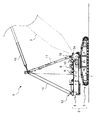
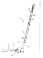
図1は、本発明の一実施形態に係るブーム起伏装置を備えたクレーンの側面図であって、吊荷作業を行なう状態の側面図である。 FIG. 1 is a side view of a crane provided with a boom hoisting device according to an embodiment of the present invention, and is a side view in a state of performing a lifting work.
図1を参照して、クレーン1は、機体2と、この機体2に起伏可能に設けられたブーム3と、このブーム3を起伏させるためのブーム起伏装置4とを備えている。
Referring to FIG. 1, a crane 1 includes a
機体2は、クローラ式の下部走行体5と、この下部走行体5上に旋回可能に搭載された上部旋回体6とを備えている。上部旋回体6は、前記下部走行体5上に設けられた旋回フレーム7と、この旋回フレーム7上に設けられたウインチ8、9、10とを備えている。
The
ブーム3は、前記旋回フレーム7の前部に対しブームフットピン3aによって起伏可能に軸支されており、図示の作業姿勢では前傾姿勢になっている。
The
ブーム起伏装置4は、前記旋回フレーム7の前部に設けられたマスト11と、機体2の後部、より詳しくは旋回フレーム7の後部に着脱可能に設けられた下部スプレッダ12と、これらマスト11と下部スプレッダ12との間に巻回され、その一端がウインチ8に連結されたロープ14と、マスト11と前記ブーム3とを連結するガイライン15とを備えている。そして、ウインチ8によってロープ14を巻き取ると、マスト11が後方へ倒れこむのに随伴してブーム3が起立する一方、ロープ14を繰り出すと、マスト11が起立する(または前傾姿勢になる)のに随伴してブーム3が倒れ込む。
The boom hoisting device 4 includes a
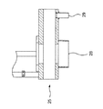
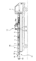
図2は、図1のマストを拡大して示す平面図である。図3は、図1のマストの側面一部略図である。図4は、図1にマストに着脱可能な折り返し部材を示す正面図である。 FIG. 2 is an enlarged plan view showing the mast of FIG. FIG. 3 is a partial schematic side view of the mast of FIG. FIG. 4 is a front view showing the folding member that can be attached to and detached from the mast in FIG. 1.
図1〜図4を参照して、マスト11は、マスト本体16と、前記下部スプレッダ12との間でロープ14が巻回される上部スプレッダ17と、前記マスト本体16に着脱可能な折り返し部材18とを備えている。
1 to 4, the
マスト本体16は、その基端部が前記旋回フレーム7に対してマストフットピン19により回動可能に軸支されている一方、その先端部において上部スプレッダ17を保持している。
The
このマスト本体16は、前記マストフットピン19により軸支される左右一対のポスト20と、これらポスト20を互いに連結する複数の連結部材21とを備えている。
The
前記各ポスト20は、当該各ポスト20の先端部に設けられ、機体2から取り外された下部スプレッダ12を取付可能なブラケット(取付部)20aと、このブラケット20aよりもマスト本体16(各ポスト20)の基端側に設けられた一対の突起板(突起部)22、23とをそれぞれ備えている。
Each
ブラケット20aは、左右方向に貫通する孔を有し、この孔に図外のピンを挿入することにより、下部スプレッダ12を取り付けることが可能となっている。
The
各突起板22、23は、詳しくは後述するが、下部スプレッダ12に当接して当該下部スプレッダ12を傾動させることにより、前記ブラケット20aに対して下部スプレッダ12を位置決めするためのものである。具体的に、突起板22、23は、ポスト20の長手方向に離間して配置されている。また、各突起板22、23は、ポスト20の側面のうち、相手側のポスト20とは反対の位置(左右方向で外側)となる側面に固定され、前記ポスト20の表面から突出している。各突起板22の突出部分は、ポスト20の表面と略平行する平坦部22aと、この平坦部22aからポスト20の先端側に進行するに従い徐々に突出する向きの傾斜部22bとをそれぞれ有している。同様に、各突起板23の突出部分も、ポスト20の表面と略平行する平坦部23aと、この平坦部23aからポスト20の先端側に進行するに従い徐々に突出する向きの傾斜部23bとをそれぞれ有している。各突起板22、23の高さを比較すると、平坦部22aが平坦部23aよりも高く、かつ、傾斜部22bが傾斜部23bよりも高くなっている。
As will be described in detail later, each of the
また、前記各ポスト20は、当該各ポスト20の基端側の位置で左右方向の外側に突出する突出板24及び突出板(第1着脱部)34をそれぞれ有している。これら突出板24、34に対しては、後述する使用姿勢とされた折り返し部材18(図4参照)を取り付けることができる。具体的に、突出板24、34は、各ポスト20の最も基端部側に配置された連結部材21に対応(対向)する位置に設けられている。突出板24、34には、折り返し部材18を挿通するための挿通孔24a、34aがそれぞれ形成されている。また、左側のポスト20は、前記突出板24よりも先端側の位置で左方向に突出する突出板(第2着脱部)35を有している。この突出板35と前記突出板24に対しては、後述する格納姿勢とされた折り返し部材18を取り付けることができる。具体的に、突出板35は、折り返し部材18を挿通するための挿通孔35aが形成されている。この挿通孔35aは、前記挿通孔24a、34a同士の距離を半径とし、前記挿通孔24aを中心としたときの円周上に配置されている。
Each
上部スプレッダ17は、前記下部スプレッダ12からのロープ14が巻回される複数のシーブを有し、前記マスト本体16(各ポスト20)の先端部に固定されたものである。なお、上部スプレッダ17は、後述するマスト11の取り外し作業の際においても、常時マスト本体16の先端部に固定されている。
The
折り返し部材18は、上部スプレッダ17と下部スプレッダ12との間のロープ14を折り返すための支点として機能する。本実施形態の折り返し部材18は、コの字型に折り曲げられた金属棒により形成されている。この折り返し部材18は、前記各挿通孔24a、34a、35aに挿通可能な一対の挿通部18aと、これら挿通部18a同士を連結する連結部18bとを備えている。そして、連結部18bは、各挿通部18aを各挿通孔24a、34aにそれぞれ挿入することにより各ポスト20の上に跨るように配置された使用姿勢で各ポスト20に取り付けられる一方、各挿通部18aを各挿通孔24a、35aにそれぞれ挿入することによりポスト20の長手方向に沿った格納姿勢で左側のポスト20に取り付けられることになる。前記使用姿勢においては、連結部18bが下部スプレッダ12と上部スプレッダ17との間のロープ14と交差するように配置されることとなるため、当該連結部18bを支点としてロープ14を折り返すことができる。一方、前記格納姿勢においては、折り返し部材18の長手方向がマスト11の長手方向に沿って配置されるため、前記折り返し作業が不要のときに折り返し部材18を嵩張ることなく格納することができる。
The folding
本実施形態では、マスト本体16に対して使用姿勢又は格納姿勢で折り返し部材18を着脱する構成について説明した。しかし、折り返し部材18の一方の挿通部18aを挿通孔24aに回転可能に挿通した状態で左側のポスト20に取り付けることにより、図2の矢印Y1に示すように、他方の挿通部18aを挿通孔34a、35aの何れかの挿通位置に回転させて、前記使用姿勢と格納姿勢とを切り換えるように構成することもできる。
In the present embodiment, the configuration in which the
また、本実施形態では、マスト11(マスト本体16)の基端部に折り返し部材18を取り付けた構成について説明したが、折り返し部材18の取付位置はマスト11の基端部に限定されない。つまり、折り返し部材18は、上部スプレッダ17よりもマスト11の基端部側の位置に取り付けられていれば、上部スプレッダ17と下部スプレッダ12との間のロープ14を折り返すための支点として利用することが可能である。
In the present embodiment, the configuration in which the
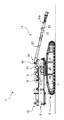
図5は、図1のクレーンにおける下部スプレッダを拡大して示す側面図である。図6は、図5の下部スプレッダの背面図である。図7は、図5のVII―VII線断面図である。 FIG. 5 is an enlarged side view showing a lower spreader in the crane of FIG. FIG. 6 is a rear view of the lower spreader of FIG. 7 is a cross-sectional view taken along line VII-VII in FIG.
図1、図5〜図7を参照して、下部スプレッダ12は、左右一対の脚部25と、これら脚部25上に固定された箱状の支持体26と、この支持体26上に支持された複数のシーブ27とを備えている。下部スプレッダ12は、その側面形状において、シーブ27の上端から脚部25の下面までの上下寸法が、前後寸法よりも長くなっている。以下、このシーブ27の上端から脚部25の下端までの寸法を下部スプレッダ12の長手寸法として説明する。
Referring to FIGS. 1 and 5 to 7, the
各脚部25には、それぞれ左右方向の外側に突出する第1当接部28及び第2当接部29が形成されている。各当接部28、29は、前記マスト本体16の突起板22、23と当接して下部スプレッダ12を傾動させるためのものである。図5及び図7に示すように、第1当接部28と第2当接部29とは、それぞれ同等の高さ寸法(突出寸法)を有している一方、第1当接部28は、第2当接部29に比べて大きな直径寸法を有している。また、第1当接部28は、第2当接部29よりも下、かつ、後ろに配置されている。このような各当接部28、29の配置に対応して、各脚部25の下面は、第1当接部28の外側面と略平行となる曲面を有する円弧部25aと、この円弧部25aから前方へ進行するに応じて上に向かう傾斜部25bと、この傾斜部25bの前で第2当接部の外側面と略平行となる曲面を有する円弧部25cとを有している。
Each
支持体26上には、左右一対の取付板30が立設されている。これら取付板30の間隔は、前記各ポスト20に設けられたブラケット20aの間隔に対応して設定されている。また、支持体26上には、複数枚のブラケット31が立設され、これらブラケット31を回転軸32が左右方向に貫いている。回転軸32は、中空の軸であり、各シーブ27を回転可能に軸支している。
A pair of left and right mounting
このように構成されたクレーン1は、小さな形態とし、かつ、重量を軽くした状態で搬送するために、分解される。以下、搬送時の分解方法について説明する。 The crane 1 thus configured is disassembled in order to be transported in a small form and with a reduced weight. Hereinafter, a disassembling method during conveyance will be described.
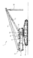
図8〜13は、それぞれクレーンの分解手順を示す側面図である。具体的に、図8は、ブームが取り外された状態を示している。図9は、マストを前方に倒伏させた状態を示している。図10は、下部スプレッダを取り外した状態を示している。図11は、下部スプレッダを移動させている状態を示している。図12は、下部スプレッダの姿勢を変えている状態を示している。図13は、ロープを結束する状態を示している。 8-13 is a side view which shows the disassembly procedure of a crane, respectively. Specifically, FIG. 8 shows a state where the boom is removed. FIG. 9 shows a state where the mast is laid down forward. FIG. 10 shows a state where the lower spreader is removed. FIG. 11 shows a state where the lower spreader is moved. FIG. 12 shows a state where the posture of the lower spreader is changed. FIG. 13 shows a state in which the ropes are bound.
図1の状態にあるクレーン1を分解する場合には、まず、ブーム3を前方に倒伏させた状態で当該ブーム3を機体2から取り外して図8に示す状態とする。
When disassembling the crane 1 in the state of FIG. 1, first, the
次に、図9に示すように、マスト11を水平若しくは前下がりとなる姿勢に倒伏させ、この状態でロープ14の一端をウインチ8から取り外す。このようにマスト11を前方に倒伏させた状態においては、マスト11の各ポスト20の間で、かつ、連結部材21の上にロープ14が配置されることになるが、このロープ14を上から跨ぐようにして、各ポスト20に対し折り返し部材18を使用姿勢(図2参照)で取り付ける。これにより、ロープ14が各ポスト20、最も基端部側の連結部材21及び折り返し部材18によって囲まれることとなり、当該ロープ14がマスト11の左右外側に脱落するのを防止することができる。
Next, as shown in FIG. 9, the
図10に示すように、外部のクレーンのフックHを下部スプレッダ12の回転軸32の内側を通したリングRに係止させるとともに、この外部のクレーンを利用して、機体2から下部スプレッダ12を取り外し、前記クレーンによって機体2から下部スプレッダ12を持ち上げる。このとき、下部スプレッダ12は、その長手方向(シーブ27の上面と脚部25の下面とを結ぶ方向)が上下方向に向いた姿勢となる。
As shown in FIG. 10, the hook H of the external crane is locked to the ring R that passes through the inside of the
そして、前記クレーンKによって下部スプレッダ12を前方へ移動させる。この移動に応じて、下部スプレッダ12に接続されたロープ14は、図11に示すように、前記折り返し部材18を支点として折り返されることになる。
Then, the
次に、図11に示すように、下部スプレッダ12の第1当接部28を突起板22の平坦部22a上に載置するとともに、この状態でさらに下部スプレッダ12を前方へ移動させる。そうすると、図12に示すように、第1当接部28と突起板22の傾斜部22bとが当接し、この状態でクレーン(フックH)がさらに前進すると、下部スプレッダ12が第1当接部28と突起板22との接点を中心として前方へ傾動することになる。この傾動が進行し、第1当接部28が突起板22を乗り越えそうになると、図12に示すように、下部スプレッダ12の各円弧部25c(図5参照)が各ポスト20の上面に摺接し、下部スプレッダ12がさらに前に倒れて、第2当接部29が突起板23の平坦部23a上に配置されることになる。
Next, as shown in FIG. 11, the
さらに、外部のクレーン(フックH)を前進させると、第2当接部29と突起板23の傾斜部23bとが当接し、第2当接部29と突起板23との接点を中心として下部スプレッダ12が前に倒れ、図13に示すように、当該下部スプレッダ12の各脚部25の前面が各ポスト20の上面に当接した状態、つまり、下部スプレッダ12の長手方向がマスト11の長手方向に沿った横倒しの状態となる。この状態において、下部スプレッダ12の各取付板30の孔と、各ポスト20のブラケット20aの孔とが合致した状態となり、これらの孔に共通のピンを挿入することにより、下部スプレッダ12をマスト11に取り付けることができる。
Further, when the external crane (hook H) is advanced, the
次いで、折り返し部材18と下部スプレッダ12との間のロープを、マスト11に対してロープL等を利用して結束する。そして、マストフットピン19を抜いてマスト11を機体2から取外し、マスト11、下部スプレッダ12及びロープ14を一体とした状態で、図14に示すように、トラックTにより搬送することができる。
Next, the rope between the folding
以上説明したように、前記実施形態によれば、上述のようにブーム起伏装置4を機体2から取り外すことができるので、クレーン1の輸送性の向上、分解作業時間の短縮、及びコストダウンを図ることができる。
As described above, according to the embodiment, since the boom hoisting device 4 can be detached from the
つまり、上部スプレッダ17と下部スプレッダ12との間に巻回されたロープ14(具体的には上部スプレッダ17と下部スプレッダ12との間に多数本掛けされて多数本の束状になっているロープ14)をマスト本体16に沿って這わせ、当該ロープを押さえ込むように折り返し部材18をマスト本体16に取り付ける。そして、ロープ14が折り返し部材18を支点として折り返されるように、下部スプレッダ12をマスト本体16基端側から先端側へ移動させて、マスト本体16に設けられたブラケット20aに取り付ける。これにより、ロープ14を整然と保持しながらマスト11と下部スプレッダ12とを一体にして機体2から取り外すことができるので、分解作業の時間短縮を図ることができる。なお、上部スプレッダ17が下部スプレッダ12から離間する方向にマスト本体16を傾動させることで、ブーム起伏用のウインチ8からロープ14が引き出され、当該ウインチ8からのロープ14の取り外し作業も容易になる。また、上述のように機体2からマスト11及び下部スプレッダ12を一体にして取り外す作業は、組立分解用の補助クレーンを2台稼動させなくても1台の稼動で行えるので、分解作業のコストダウンを図ることもできる。さらに、マスト11及び下部スプレッダ12を一体にして輸送できるほか、機体2の輸送重量も低減できるので、クレーン1の輸送性も向上できる。
That is, a
前記実施形態のように、連結部材21に対応する位置で、かつ、連結部材21との間にロープ14を挟んだ位置に折り返し部材18を取付可能とした構成とすることにより、下部スプレッダ12と上部スプレッダ17との間のロープ14の途中部が連結部材21と折り返し部材18との間に挟まれているため、当該折り返し部材18による折り返し前の段階においても、両ポスト20の間からロープ14が抜け落ちることを抑制することができる。
As in the above-described embodiment, the
前記実施形態のように、使用姿勢だけでなく格納姿勢でも折り返し部材18をマスト本体16に取付可能に構成することにより、折り返し部材18が使用姿勢でのみマスト本体16に取付可能に構成されている場合と比較して、ブーム起伏装置4の取り外し作業の効率化を図ることができる。その理由は、以下の通りである。
As in the above-described embodiment, the folding
折り返し部材18が使用姿勢でのみマスト本体16に取付可能に構成されている場合には、次のような問題が生じる。マスト本体16に折り返し部材18を取り付けたまま、上部スプレッダ17と下部スプレッダ12とを離間させる方向にマスト本体16を傾動させると、折り返し部材18の上にロープ14が載ってしまい、折り返し部材18をマスト本体16から取り外しにくくなる。他方、マスト本体16の上記傾動以前に折り返し部材18を予め取り外しておくと、折り返し部材18がマスト本体16の傾動中に機体2から落下して取り外し作業の遅延を招くおそれがある。
When the folding
これに対し、折り返し部材18が使用姿勢だけでなく格納姿勢でも取付可能な構成とすることにより、折り返し部材18をマスト本体16に格納姿勢で取り付けたまま、上部スプレッダ17を下部スプレッダ12から離間する方向にマスト本体16を傾動させても、折り返し部材18の上にロープが載らないので、折り返し部材18をマスト本体16から取り外しやすくなる。また、折り返し部材18がマスト本体16の傾動中に機体から落下することもないので、ブーム起伏装置4の取り外し作業を遅滞なく進めることができる。
On the other hand, the folding
前記実施形態のように、折り返し部材18を使用姿勢と格納姿勢との間で回転可能に構成することにより、折り返し部材18の一方の挿通部18aをマスト本体16から脱着し、突出板24に挿通された折り返し部材18の挿通部18aを中心にして折り返し部材18を回転させ、折り返し部材18の挿通部18aを突出板34に装着して前記使用姿勢とすることができる一方、折り返し部材18の挿通部18aを突出板35に装着して前記格納姿勢とすることができる。このように折り返し部材18の一方の挿通部18aをマスト本体16に取り付けたまま姿勢変更を行えるようにしてあるので、折り返し部材18の紛失を防止できる上、折り返し部材18の姿勢変更作業の時間短縮を図ることもできる。
As in the above-described embodiment, the folding
前記実施形態のように、ブラケット20aの近傍で、かつ、ブラケット20aよりもマスト本体16の基端側に設けられた突起板22、23と、下部スプレッダ12に設けられ、機体2から取り外された下部スプレッダ12をブラケット20aに移動させるに際し、突起板22、23に当接させて下部スプレッダ12を傾動させるための当接部28、29とを備えた構成によれば、機体2から取り外した下部スプレッダ12を分解組立用の補助クレーンによって吊下げてマスト本体16のブラケット20aまで移動させる際に、下部スプレッダ12の当接部28、29をマスト本体16の突起板22、23に当接させ、当接部28、29と突起板22、23との接点を支点として下部スプレッダ12を傾動させることにより、下部スプレッダ12をブラケット20aに位置決めすることができ、ブーム起伏装置4の取り外し作業に要する時間をより一層短縮することができる。
As in the above-described embodiment, the
1 クレーン
2 機体
3 ブーム
4 ブーム起伏装置
8 ウインチ
11 マスト
12 下部スプレッダ
14 ロープ
16 マスト本体
17 上部スプレッダ
18 折り返し部材
20 ポスト
20a ブラケット(取付部)
21 連結部材
22、23 突起板(突起部)
24 突出板
28、29 当接部
34 突出板(第1着脱部)
35 突出板(第2着脱部)
DESCRIPTION OF SYMBOLS 1
21 Connecting
24
35 Protruding plate (second detachable part)
Claims (5)
前記機体に着脱可能に設けられた下部スプレッダと、
前記機体に対して回動可能で、かつ、着脱可能に取り付けられたマスト本体と、
前記マスト本体の先端部に取り付けられ、前記下部スプレッダとの間でロープを巻回するための上部スプレッダと、
前記マスト本体に設けられ、前記機体から取り外した下部スプレッダを取り付け可能な取付部と、
前記下部スプレッダと上部スプレッダとの間に巻回されたロープと交差する方向に延びるように、前記取付部よりも前記マスト本体の基端部側に取り付けられ、前記機体から取り外した下部スプレッダを前記取付部に移動させるに際し、前記ロープの途中部を折り返すための支点となる折り返し部材とを備えていることを特徴とするブーム起伏装置。 A boom hoisting device for hoisting a boom provided on a crane body with respect to the body,
A lower spreader detachably provided on the airframe;
A mast main body that is rotatable with respect to the airframe and is detachably attached;
An upper spreader that is attached to the tip of the mast body and winds a rope between the lower spreader;
A mounting portion provided on the mast body and capable of mounting a lower spreader removed from the airframe;
The lower spreader, which is attached to the base end side of the mast body with respect to the attachment portion and is detached from the body, extends in a direction intersecting with the rope wound between the lower spreader and the upper spreader. A boom raising and lowering device comprising: a folding member serving as a fulcrum for folding a midway portion of the rope when moving to the attachment portion.
前記下部スプレッダに設けられ、前記機体から取り外された下部スプレッダを前記取付部に移動させるに際し、前記突起部に当接させて前記下部スプレッダを傾動させるための当接部とを備え、
前記突起部は、前記下部スプレッダの当接部との接点を支点として前記下部スプレッダを傾動させたときに、前記下部スプレッダが前記取付部に位置決めされるように配置されていることを特徴とする請求項1〜4の何れか1項に記載のブーム起伏装置。 A projection provided in the vicinity of the mounting portion and closer to the base end side of the mast body than the mounting portion;
A lower contact spreader provided on the lower spreader, and when the lower spreader removed from the airframe is moved to the mounting portion, a contact portion for contacting the protrusion and tilting the lower spreader;
The protrusion is arranged so that the lower spreader is positioned on the mounting portion when the lower spreader is tilted with a contact point with the contact portion of the lower spreader as a fulcrum. The boom hoisting device according to any one of claims 1 to 4.
Priority Applications (1)
| Application Number | Priority Date | Filing Date | Title |
|---|---|---|---|
| JP2008177786A JP2010018355A (en) | 2008-07-08 | 2008-07-08 | Boom derricking device |
Applications Claiming Priority (1)
| Application Number | Priority Date | Filing Date | Title |
|---|---|---|---|
| JP2008177786A JP2010018355A (en) | 2008-07-08 | 2008-07-08 | Boom derricking device |
Publications (1)
| Publication Number | Publication Date |
|---|---|
| JP2010018355A true JP2010018355A (en) | 2010-01-28 |
Family
ID=41703656
Family Applications (1)
| Application Number | Title | Priority Date | Filing Date |
|---|---|---|---|
| JP2008177786A Pending JP2010018355A (en) | 2008-07-08 | 2008-07-08 | Boom derricking device |
Country Status (1)
| Country | Link |
|---|---|
| JP (1) | JP2010018355A (en) |
Cited By (6)
| Publication number | Priority date | Publication date | Assignee | Title |
|---|---|---|---|---|
| JP2012148848A (en) * | 2011-01-18 | 2012-08-09 | Kobelco Cranes Co Ltd | Adapter for raising mast, mast raising gear and winch detaching method |
| DE102014201466A1 (en) | 2013-01-29 | 2014-07-31 | Kobelco Cranes Co., Ltd. | Liftable and lowerable element for a crane |
| CN105384090A (en) * | 2014-08-20 | 2016-03-09 | 利勃海尔-韦尔克埃英根有限公司 | Automatic erecting of a crane |
| JP2017160012A (en) * | 2016-03-09 | 2017-09-14 | コベルコクレーン株式会社 | Mast guy link storage device |
| DE102017111345A1 (en) | 2016-05-26 | 2017-11-30 | Kobelco Construction Machinery Co., Ltd. | MAST BOOM DEVICE |
| JP2020029349A (en) * | 2018-08-23 | 2020-02-27 | コベルコ建機株式会社 | Upper spreader mounting device |
-
2008
- 2008-07-08 JP JP2008177786A patent/JP2010018355A/en active Pending
Cited By (12)
| Publication number | Priority date | Publication date | Assignee | Title |
|---|---|---|---|---|
| JP2012148848A (en) * | 2011-01-18 | 2012-08-09 | Kobelco Cranes Co Ltd | Adapter for raising mast, mast raising gear and winch detaching method |
| DE102014201466A1 (en) | 2013-01-29 | 2014-07-31 | Kobelco Cranes Co., Ltd. | Liftable and lowerable element for a crane |
| CN103964320A (en) * | 2013-01-29 | 2014-08-06 | 神钢起重机株式会社 | Raisable-lowerable Member For Crane |
| US9522812B2 (en) | 2013-01-29 | 2016-12-20 | Kobelco Cranes Co., Ltd. | Raisable-lowerable member for crane |
| DE102014201466B4 (en) * | 2013-01-29 | 2021-03-25 | Kobelco Cranes Co., Ltd. | Raisable and lowerable element for a crane |
| CN105384090A (en) * | 2014-08-20 | 2016-03-09 | 利勃海尔-韦尔克埃英根有限公司 | Automatic erecting of a crane |
| JP2017160012A (en) * | 2016-03-09 | 2017-09-14 | コベルコクレーン株式会社 | Mast guy link storage device |
| DE102017111345A1 (en) | 2016-05-26 | 2017-11-30 | Kobelco Construction Machinery Co., Ltd. | MAST BOOM DEVICE |
| US10407284B2 (en) | 2016-05-26 | 2019-09-10 | Kobelco Construction Machinery Co., Ltd. | Derricking apparatus |
| DE102017111345B4 (en) | 2016-05-26 | 2021-08-12 | Kobelco Construction Machinery Co., Ltd. | BOOM DEVICE |
| JP2020029349A (en) * | 2018-08-23 | 2020-02-27 | コベルコ建機株式会社 | Upper spreader mounting device |
| JP7135588B2 (en) | 2018-08-23 | 2022-09-13 | コベルコ建機株式会社 | Top spreader mounting device |
Similar Documents
| Publication | Publication Date | Title |
|---|---|---|
| JP5568453B2 (en) | Mobile crane and method of assembling mobile crane | |
| US9522812B2 (en) | Raisable-lowerable member for crane | |
| US9206021B2 (en) | Crane and crane assembling method | |
| JP2007302352A (en) | Crane, and crane boom derricking device | |
| JP4857880B2 (en) | Mobile crane boom mounting method and boom mounting tool | |
| JP2010018355A (en) | Boom derricking device | |
| JP6172213B2 (en) | Crane with jib | |
| JP2016222392A (en) | Mobile crane and boom standing method of mobile crane | |
| JP5592642B2 (en) | Tension rope connecting method and jib connecting method in boom working vehicle with jib provided with boom lateral deflection suppressing device | |
| JP5717419B2 (en) | Mobile crane and method of assembling mobile crane | |
| JP5547618B2 (en) | crane | |
| JP2018048014A (en) | Method for assembling mobile crane | |
| JP2003054876A (en) | Device and method for attaching and detaching side frame | |
| JP6607224B2 (en) | Hoisting device | |
| JP5504141B2 (en) | Mobile crane | |
| JP6246707B2 (en) | Boom mounting device and crane | |
| JP6683087B2 (en) | Mobile crane assembly method | |
| JP2005200206A (en) | Tower crane | |
| JP7234811B2 (en) | A crane strut, a method for folding a crane strut, and a method for assembling a crane strut | |
| JP2019112152A (en) | Crane and crane assembling method | |
| JP2019199310A (en) | Specification changing method of crane and specification-changeable crane | |
| WO2023074493A1 (en) | Crane attachment | |
| JP7435580B2 (en) | connector storage device | |
| JP7416034B2 (en) | How to assemble the crane | |
| JP2010006554A (en) | Counterweight attaching/detaching device and truck crane |