JP2010018030A - Manufacturing method of liquid-jet recording head - Google Patents
Manufacturing method of liquid-jet recording head Download PDFInfo
- Publication number
- JP2010018030A JP2010018030A JP2009212157A JP2009212157A JP2010018030A JP 2010018030 A JP2010018030 A JP 2010018030A JP 2009212157 A JP2009212157 A JP 2009212157A JP 2009212157 A JP2009212157 A JP 2009212157A JP 2010018030 A JP2010018030 A JP 2010018030A
- Authority
- JP
- Japan
- Prior art keywords
- recording
- adhesive
- ink
- liquid
- unit
- Prior art date
- Legal status (The legal status is an assumption and is not a legal conclusion. Google has not performed a legal analysis and makes no representation as to the accuracy of the status listed.)
- Granted
Links
Images


Abstract
Description
本発明は、液体供給ユニット部と記録素子ユニットとが互いに接着により結合されることにより形成される液体吐出記録ヘッドの製造方法に関する。 The present invention relates to a method for manufacturing a liquid discharge recording head formed by bonding a liquid supply unit and a recording element unit to each other by adhesion.
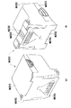
液体吐出記録ヘッドとしての記録ヘッド1は、例えば、図18に示されるように、記録素子ユニット2とタンクホルダーユニット3とから構成されている。
A
記録素子ユニット2は、複数のインク吐出口が形成されるインク吐出口形成面を有する記録素子基板11、記録素子基板11が接合される第1のプレート12、および、記録素子基板11における記録素子(ヒータ)に駆動信号を供給する電気配線基板13を主な要素として含んで構成されている。
The
第1のプレート12は、例えば、アルミナで薄板状に作られ記録素子基板11における各インク供給口にそれぞれ連通する複数のインク流路を有している。
The
図示が省略されるインクタンクユニットが着脱可能に搭載されるタンクホルダーユニット3は、そのインクタンクユニットの収容室を有するタンクホルダー15、および、流路形成部材16を主な要素として含んで構成されている。
A
流路形成部材16は、インクタンクユニットからのそれぞれのインクを第1のプレート12を介して記録素子基板11に供給するものとされる。流路形成部材16は、例えば、タンクホルダー15とは別体に樹脂で成形されてタンクホルダー15の下面に固定されている。タンクホルダー15内においてインクタンクユニットからのインクがそれぞれ供給される各インク流路にそれぞれ連通する連通路16rを複数有している。
The flow
記録素子ユニット2をタンクホルダーユニット3に結合するにあたっては、以下のように行われる。
The
記録素子ユニット2のインク供給口(第1のプレート12のインク供給口)とタンクホルダーユニット3のインク供給口(流路形成部材16の連通路16r)とを連通させるように第4の接着剤B4を流路形成部材16における連通路16rの一方の開口端の周囲に塗布され、第1のプレート12と流路形成部材16とが接着固定される。
A fourth adhesive is provided so that the ink supply port of the recording element unit 2 (ink supply port of the first plate 12) communicates with the ink supply port of the tank holder unit 3 (the
また、そのインク流路の部分以外の周囲においても、記録素子ユニット2におけるタンクホルダーユニット3が当接する部分も数ケ所、第5の接着剤B5で互いに接着固定されている。
In addition, the portions where the
第4の接着剤B4と第5の接着剤B5とは、耐インク性があり、かつ、常温で硬化し、かつ、異種材料間の線膨張差に耐えられる柔軟性のある接着剤が望ましく、例えば、吸湿硬化型のシリコーン接着剤が使用されている。 Desirably, the fourth adhesive B4 and the fifth adhesive B5 are ink-resistant, are hardened at room temperature, and are flexible enough to withstand the difference in linear expansion between different materials. For example, a moisture-absorbing curing type silicone adhesive is used.
その際、記録素子ユニット2をタンクホルダーユニット3に第4の接着剤B4および第5の接着剤B5で接着する際に、記録素子ユニット2は、流路形成部材16の所定位置に塗布される第6の接着剤B6で位置決め固定される。その第6の接着剤B6は、瞬時に硬化する接着剤が望ましく、例えば、紫外線硬化接着剤とされる。
At that time, when the
記録素子ユニット2の外部信号入力端子部分は、タンクホルダー15の一側面に、タンクホルダー15の端子位置決めピンP1(2ケ所)と電気配線基板13の端子位置決め穴H1(2ケ所)とにより位置決めされ固定される。さらに、電気配線基板13は、例えば、タンクホルダーH1500に設けられた端子結合ピンP2(6箇所)と、電気配線基板13の外部信号入力端子周辺に設けられた端子結合穴H2(6箇所)とをはめ合わされ、端子結合ピンH2を熱溶着することにより固定している。
The external signal input terminal portion of the
しかし、上述のように、吸湿硬化型のシリコーン接着剤が接着剤として使用される場合、その接着剤の硬化は、時間の経過とともに進行するので作業中におけるその硬化防止対策、あるいは、接着層の厚さを所定の厚さにするために定期的な接着剤の塗布量のばらつきを少なくするように管理する必要がある。従って、生産効率の観点からも接着剤の塗布量の厳密な管理を要することなく、記録ヘッドが迅速にかつ容易に組立てられることが要望される。 However, as described above, when a moisture-absorbing curing type silicone adhesive is used as an adhesive, the curing of the adhesive proceeds with the passage of time. In order to make the thickness a predetermined thickness, it is necessary to manage so as to reduce the variation in the amount of the adhesive periodically applied. Therefore, from the viewpoint of production efficiency, it is desired that the recording head be assembled quickly and easily without requiring strict management of the amount of adhesive applied.
以上の問題点を考慮し、本発明は、液体供給ユニット部と記録素子ユニットとが互いに接着により結合されることにより形成される液体吐出記録ヘッドの製造方法であって、接着剤の塗布量の厳密な管理を要することなく記録ヘッドを迅速にかつ容易に組立てることができる液体吐出記録ヘッドの製造方法を提供することを目的とする。 In view of the above problems, the present invention is a method for manufacturing a liquid discharge recording head formed by bonding a liquid supply unit unit and a recording element unit to each other by bonding. It is an object of the present invention to provide a method of manufacturing a liquid discharge recording head that can assemble a recording head quickly and easily without requiring strict management.
上述の目的を達成するために、本発明に係る液体吐出記録ヘッドの製造方法は、液体を吐出し記録動作を行う記録素子基板と、記録素子基板に液体を供給する液体供給路を有する板状部材とを含む記録素子ユニットと、液体を供給する液体供給源からの液体を記録素子ユニットに導く連通路を有する液体供給ユニット部と、を有する液体吐出記録ヘッドの製造方法であって、板状部材の液体供給路の一方の端部と、液体供給ユニット部の連通路の一方の端部との間に、液体供給路および連通路に連通する液体流路を有する弾性シール部材を配する工程と、
液体供給ユニット部と記録素子ユニットを、弾性シール部材が圧縮された状態で弾性シール部材の周囲を形成する接合面における複数箇所に塗布される所定の硬化時間で硬化する紫外線硬化型接着剤により仮固定した後、接合面における他の複数箇所に塗布され、紫外線硬化型接着剤の接着力よりも接着力が強く常温で所定の硬化時間より長い時間で硬化する接着剤により接着し固定する工程と、を有することを特徴とする。
In order to achieve the above-described object, a method for manufacturing a liquid discharge recording head according to the present invention includes a recording element substrate that discharges liquid and performs a recording operation, and a plate-like shape having a liquid supply path that supplies the recording element substrate with liquid A liquid discharge recording head manufacturing method comprising: a recording element unit including a member; and a liquid supply unit portion having a communication path that guides liquid from a liquid supply source that supplies liquid to the recording element unit. Disposing an elastic seal member having a liquid flow path communicating with the liquid supply path and the communication path between one end of the liquid supply path of the member and one end of the communication path of the liquid supply unit When,
The liquid supply unit and the recording element unit are temporarily bonded with an ultraviolet curable adhesive that is cured at a predetermined curing time applied to a plurality of locations on the joint surface that forms the periphery of the elastic seal member in a state where the elastic seal member is compressed. After being fixed, it is applied to a plurality of other locations on the joint surface, and is bonded and fixed with an adhesive that has a stronger adhesive strength than the ultraviolet curable adhesive and cures at room temperature for a longer time than the predetermined curing time; It is characterized by having.
本発明に係る液体吐出記録ヘッドの製造方法によれば、板状部材の液体供給路の一方の端部と、液体供給ユニット部の連通路の一方の端部との間に、液体供給路および連通路に連通する液体流路を有する弾性シール部材を配する工程を含むので記録素子ユニットの液体供給路の一方の端部と液体供給ユニット部の連通路との間に接着剤が不要となり、従って、接着剤の塗布量の厳密な管理を要することなく記録ヘッドを迅速に、かつ、容易に組立てることができる。 According to the method for manufacturing a liquid discharge recording head according to the present invention, the liquid supply path and Since an elastic seal member having a liquid flow path communicating with the communication path is included, no adhesive is required between one end of the liquid supply path of the recording element unit and the communication path of the liquid supply unit section. Accordingly, it is possible to assemble the recording head quickly and easily without requiring strict management of the adhesive application amount.
以下、図面を参照して本発明に係る液体吐出記録ヘッドの製造方法の一例が適用される液体吐出記録ヘッドを備える記録装置に係る実施形態を説明する。 Hereinafter, an embodiment according to a recording apparatus including a liquid discharge recording head to which an example of a method for manufacturing a liquid discharge recording head according to the invention is applied will be described with reference to the drawings.
なお、以下に説明する実施形態では、インクジェット記録方式を用いた記録装置としてプリンタを例に挙げ説明する。 In the embodiments described below, a printer is taken as an example of a recording apparatus using an inkjet recording method.
そして、本明細書において、「プリント」(「記録」という場合もある)とは、文字、図形等有意の情報を形成する場合のみならず、有意無意を問わず、また人間が視覚で知覚し得るように顕在化したものであるか否かを問わず、広くプリント媒体上に画像、模様、パターン等を形成する、または媒体の加工を行う場合も言うものとする。 In this specification, “print” (sometimes referred to as “recording”) is not only for forming significant information such as characters and figures, but also for human beings visually perceived regardless of significance. Regardless of whether or not it has been manifested, it also refers to a case where an image, a pattern, a pattern, or the like is widely formed on a print medium or the medium is processed.
ここで、「プリント媒体」とは、一般的なプリント装置で用いられる紙のみならず、広く、布、プラスチック・フィルム、金属板等、ガラス、セラミックス、木材、皮革等、インクを受容可能な物も言うものとする。 Here, “print medium” refers not only to paper used in general printing apparatuses, but also to materials that can accept ink, such as cloth, plastic film, metal plate, glass, ceramics, wood, leather, etc. Shall also say.
さらに、「インク」(「液体」という場合もある)とは、上記「プリント」の定義と同様広く解釈されるべきもので、プリント媒体上に付与されることによって、画像、模様、パターン等の形成またはプリント媒体の加工、或いはインクの処理(例えばプリント媒体に付与されるインク中の色材の凝固または不溶化)に供され得る液体を言うものとする。 Further, “ink” (sometimes referred to as “liquid”) is to be interpreted widely as the definition of “print” above, and it is applied to a print medium so that an image, a pattern, a pattern, etc. It shall refer to a liquid that can be subjected to formation or processing of the print medium, or ink processing (eg, solidification or insolubilization of the colorant in the ink applied to the print medium).
[装置本体]
図8及び図9にインクジェット記録方式を用いたプリンタの概略構成を示す。図8において、この実施形態におけるプリンタの装置本体M1000の外殻は、下ケースM1001、上ケースM1002、アクセスカバーM1003及び排出トレイM1004を含む外装部材と、その外装部材内に収納されたシャーシM3019(図9参照)とから構成される。
[Device main unit]
8 and 9 show a schematic configuration of a printer using the ink jet recording method. In FIG. 8, the outer shell of the printer main body M1000 of this embodiment includes an exterior member including a lower case M1001, an upper case M1002, an access cover M1003, and a discharge tray M1004, and a chassis M3019 ( (See FIG. 9).
シャーシM3019は、所定の剛性を有する複数の板状金属部材によって構成され、記録装置の骨格をなし、後述の各記録動作機構を保持するものとなっている。 The chassis M3019 is composed of a plurality of plate-shaped metal members having a predetermined rigidity, forms a skeleton of the recording apparatus, and holds each recording operation mechanism described later.
また、前記下ケースM1001は装置本体M1000の外装の略下半部を、上ケースM1002は装置本体M1000の外装の略上半部をそれぞれ形成しており、両ケースの組合せによって内部に後述の各機構を収納する収納空間を有する中空体構造をなしている。装置本体M1000の上面部及び前面部には、それぞれ、開口部が形成されている。 The lower case M1001 forms a substantially lower half part of the exterior of the apparatus main body M1000, and the upper case M1002 forms a substantially upper half part of the exterior of the apparatus main body M1000. A hollow body structure having a storage space for storing the mechanism is formed. An opening is formed in each of the upper surface portion and the front surface portion of the apparatus main body M1000.
さらに、排出トレイM1004は、その一端部が下ケースM1001に回転自在に保持され、その回転によって下ケースM1001の前面部に形成される前記開口部を開閉させ得るようになっている。このため、記録動作を実行させる際には、排出トレイM1004を前面側へと回転させて開口部を開成させることにより、ここから記録シートが排出可能となると共に排出された記録シートPを順次積載し得るようになっている。また、排紙トレイM1004には、2枚の補助トレイM1004a,M1004bが収納されており、必要に応じて各トレイを手前に引き出すことにより、用紙の支持面積を3段階に拡大、縮小させ得るようになっている。 Further, one end of the discharge tray M1004 is rotatably held by the lower case M1001, and the opening formed on the front surface of the lower case M1001 can be opened and closed by the rotation. For this reason, when executing the recording operation, the discharge tray M1004 is rotated to the front side to open the opening so that the recording sheets can be discharged and the discharged recording sheets P are sequentially stacked. It has come to be able to do. In addition, the discharge tray M1004 contains two auxiliary trays M1004a and M1004b. By pulling out each tray as needed, the sheet support area can be expanded or reduced in three stages. It has become.
アクセスカバーM1003は、その一端部が上ケースM1002に回転自在に保持され、上面に形成される開口部を開閉し得るようになっており、このアクセスカバーM1003を開くことによって本体内部に収納されている記録ヘッドカートリッジH1000あるいはインクタンクH1900等の交換が可能となる。なお、ここでは特に図示しないが、アクセスカバーM1003を開閉させると、その裏面に形成された突起がカバー開閉レバーを回転させるようになっており、そのレバーの回転位置をマイクロスイッチなどで検出することにより、アクセスカバーの開閉状態を検出し得るようになっている。 One end of the access cover M1003 is rotatably held by the upper case M1002, and can open and close an opening formed on the upper surface. By opening the access cover M1003, the access cover M1003 is housed inside the main body. It is possible to replace the print head cartridge H1000 or the ink tank H1900. Although not specifically shown here, when the access cover M1003 is opened and closed, the protrusion formed on the back surface rotates the cover opening and closing lever, and the rotation position of the lever is detected by a micro switch or the like. Thus, the open / closed state of the access cover can be detected.
また、上ケースM1002の後部上面には、電源キーE0018及びレジュームキーE0019が押下可能に設けられると共に、LED E0020が設けられており、電源キーE0018を押下すると、LED E0020が点灯し記録可能であることをオペレータに知らせるものとなっている。また、LED E0020は点滅の仕方や色の変化をさせたり、プリンタのトラブル等をオペレータに知らせる等種々の表示機能を有する。さらに、ブザーE0021(図7)をならすこともできる。なお、トラブル等が解決した場合には、レジュームキーE0019を押下することによって記録が再開されるようになっている。 On the upper surface of the rear part of the upper case M1002, a power key E0018 and a resume key E0019 are provided so that they can be pressed, and an LED E0020 is provided. When the power key E0018 is pressed, the LED E0020 lights up and recording is possible. This is to inform the operator. Further, the LED E0020 has various display functions such as blinking method and color change, and informing the operator of printer troubles. Further, the buzzer E0021 (FIG. 7) can be leveled. When the trouble is solved, the recording is resumed by pressing the resume key E0019.
[記録動作機構]
次に、プリンタの装置本体M1000に収納、保持される本実施形態における記録動作機構について説明する。
[Recording mechanism]
Next, the recording operation mechanism in the present embodiment that is housed and held in the printer apparatus main body M1000 will be described.
本実施形態における記録動作機構としては、記録シートPを装置本体内へと自動的に給送する自動給送部M3022と、自動給送部から1枚ずつ送出される記録シートPを所定の記録位置へと導くと共に、記録位置から排出部M3030へと記録シートPを導く搬送部M3029と、記録位置に搬送された記録シートPに所望の記録を行なう記録部と、前記記録部等に対する回復処理を行う回復部(M5000)とから構成されている。 As a recording operation mechanism in the present embodiment, an automatic feeding unit M3022 that automatically feeds the recording sheet P into the apparatus main body, and a recording sheet P that is sent one by one from the automatic feeding unit are recorded in a predetermined manner. A conveyance unit M3029 for guiding the recording sheet P from the recording position to the discharge unit M3030, a recording unit for performing desired recording on the recording sheet P conveyed to the recording position, and a recovery process for the recording unit And a recovery unit (M5000).
(記録部)
ここで、記録部について説明するに、その記録部は、キャリッジ軸M4021によって移動可能に支持されたキャリッジM4001と、このキャリッジM4001に着脱可能に搭載される記録ヘッドカートリッジH1000とからなる。
(Recording part)
Here, the recording unit will be described. The recording unit includes a carriage M4001 that is movably supported by a carriage shaft M4021, and a recording head cartridge H1000 that is detachably mounted on the carriage M4001.
記録ヘッドカートリッジ
まず、記録部に用いられる記録ヘッドカートリッジについて図10〜11に基づき説明する。
Recording Head Cartridge First, the recording head cartridge used in the recording unit will be described with reference to FIGS.
この実施形態における記録ヘッドカートリッジH1000は、図10に示すようにインクを貯留するインクタンクH1900と、このインクタンクH1900から供給されるインクを記録情報に応じてノズルから吐出させる記録ヘッドH1001とを有する。記録ヘッドH1001は、後述するキャリッジM4001に対して着脱可能に搭載される、いわゆるカートリッジ方式を採るものとなっている。 As shown in FIG. 10, the recording head cartridge H1000 in this embodiment includes an ink tank H1900 that stores ink, and a recording head H1001 that discharges ink supplied from the ink tank H1900 from nozzles according to recording information. . The recording head H1001 adopts a so-called cartridge system that is detachably mounted on a carriage M4001 described later.
ここに示す記録ヘッドカートリッジH1000では、写真調の高画質なカラー記録を可能とするため、インクタンクとして、例えば、ブラック、ライトシアン、ライトマゼンタ、シアン、マゼンタ及びイエローの各色独立のインクタンクH1900が用意されており、図11に示すように、それぞれが記録ヘッドH1001に対して着脱自在となっている。 In the recording head cartridge H1000 shown here, for example, black, light cyan, light magenta, cyan, magenta and yellow ink tanks H1900 are prepared as ink tanks in order to enable high-quality color recording with photographic tone. As shown in FIG. 11, each is detachable from the recording head H1001.
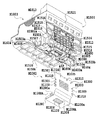
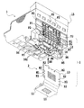
そして,記録ヘッドH1001は、図2の分解斜視図に示すように、記録素子基板H1100、第1のプレートH1200、電気配線基板H1300、第2のプレートH1400、タンクホルダーH1500、流路形成部材H1600、フィルターH1700、シールゴムH1800、および、パッキン部材H2000から構成されている。 As shown in the exploded perspective view of FIG. 2, the recording head H1001 includes a recording element substrate H1100, a first plate H1200, an electric wiring substrate H1300, a second plate H1400, a tank holder H1500, a flow path forming member H1600, The filter H1700, a seal rubber H1800, and a packing member H2000 are included.
記録素子基板H1100には、図17に示されるように、Si基板の片面にインクを吐出するための複数の記録素子(電気熱変換素子)H1103と、各記録素子H1103に電力を供給するAl等の電気配線とが成膜技術により形成され、この記録素子に対応した複数のインク流路と複数の吐出口H1100Tとがフォトリソグラフィ技術により形成されると共に、複数のインク流路にインクを供給するためのインク供給口が裏面に開口するように形成されている。また、記録素子基板H1100は、第1のプレートH1200に接着固定されており、ここには、記録素子基板H1100にインクを供給するためのインク供給口H1201が形成されている。さらに、第1のプレートH1200には、開口部H1400aを有する第2のプレートH1400が接着固定されており、この第2のプレートH1400を介して、電気配線基板H1300が記録素子基板H1100に対して電気的に接続されるよう保持されている。この電気配線基板H1300は、記録素子基板H1100にインクを吐出するための電気信号を印加するものであり、記録素子基板H1100に対応する電気配線と、この電気配線端部に位置し本体からの電気信号を受け取るための外部信号入力端子H1301とを有しており、外部信号入力端子H1301は、後述のタンクホルダーH1500の背面側に位置決め固定されている。 As shown in FIG. 17, the recording element substrate H1100 includes a plurality of recording elements (electrothermal conversion elements) H1103 for ejecting ink on one side of the Si substrate, Al that supplies power to each recording element H1103, and the like. Are formed by a film forming technique, a plurality of ink flow paths corresponding to the recording element and a plurality of ejection openings H1100T are formed by a photolithography technique, and ink is supplied to the plurality of ink flow paths. The ink supply port is formed so as to open on the back surface. The recording element substrate H1100 is bonded and fixed to the first plate H1200, and an ink supply port H1201 for supplying ink to the recording element substrate H1100 is formed here. Further, a second plate H1400 having an opening H1400a is bonded and fixed to the first plate H1200, and the electric wiring substrate H1300 is electrically connected to the recording element substrate H1100 via the second plate H1400. Are kept connected. The electrical wiring substrate H1300 applies an electrical signal for ejecting ink to the recording element substrate H1100. The electrical wiring substrate H1300 is located at an end portion of the electrical wiring and corresponds to the electrical wiring from the main body. An external signal input terminal H1301 for receiving a signal is provided, and the external signal input terminal H1301 is positioned and fixed on the back side of a tank holder H1500 described later.
一方、インクタンクH1900を着脱可能に保持するタンクホルダーH1500には、流路形成部材H1600が例えば、超音波溶着により固定され、インクタンクH1900から第1のプレートH1200に亘るインク流路の一部を形成している。また、インクタンクH1900と係合するインク流路H1501のインクタンク側端部には、フィルターH1700が設けられており、外部からの塵埃の侵入を防止し得るようになっている。また、インクタンクH1900との係合部にはシールゴムH1800が装着され、係合部からのインクの蒸発を防止し得るようになっている。 On the other hand, a flow path forming member H1600 is fixed to the tank holder H1500 that detachably holds the ink tank H1900 by, for example, ultrasonic welding, and a part of the ink flow path extending from the ink tank H1900 to the first plate H1200 is provided. Forming. In addition, a filter H1700 is provided at an end of the ink flow path H1501 that engages with the ink tank H1900 on the ink tank side so that entry of dust from the outside can be prevented. Further, a seal rubber H1800 is attached to the engaging portion with the ink tank H1900 so that ink can be prevented from evaporating from the engaging portion.
さらに、前述のようにタンクホルダーH1500、流路形成部材H1600、フィルターH1700及びシールゴムH1800から構成されるタンクホルダー部と、前記記録素子基板H1100、第1のプレートH1200、電気配線基板H1300及び第2のプレートH1400から構成される記録素子部とを、パッキン部材H2000を介して結合することにより、記録ヘッドH1001を構成している。 Further, as described above, the tank holder portion composed of the tank holder H1500, the flow path forming member H1600, the filter H1700, and the seal rubber H1800, the recording element substrate H1100, the first plate H1200, the electric wiring substrate H1300, and the second A recording head H1001 is configured by coupling a recording element portion composed of the plate H1400 via a packing member H2000.
(キャリッジ)
次に、図9を参照して記録ヘッドカートリッジH1000を搭載するキャリッジM4001を説明する。
(carriage)
Next, a carriage M4001 on which the recording head cartridge H1000 is mounted will be described with reference to FIG.
図9に示すように、キャリッジM4001には、キャリッジM4001と係合し記録ヘッドH1001をキャリッジM4001上の所定の装着位置に案内するためのキャリッジカバーM4002と、記録ヘッドH1001のタンクホルダーH1500と係合し記録ヘッドH1001を所定の装着位置にセットさせるよう押圧するヘッドセットレバーM4007とが設けられている。
すなわち、ヘッドセットレバーM4007はキャリッジM4001の上部にヘッドセットレバー軸に対して回動可能に設けられると共に、記録ヘッドH1001との係合部には、ばね付勢されるヘッドセットプレート(不図示)が備えられ、このばね力によって記録ヘッドH1001を押圧しながらキャリッジM4001に装着する構成となっている。
As shown in FIG. 9, the carriage M4001 is engaged with the carriage M4001 and engaged with the carriage cover M4002 for guiding the recording head H1001 to a predetermined mounting position on the carriage M4001, and the tank holder H1500 of the recording head H1001. And a head set lever M4007 that presses the recording head H1001 to set it at a predetermined mounting position.
That is, the head set lever M4007 is provided on the upper portion of the carriage M4001 so as to be rotatable with respect to the head set lever shaft, and a spring-set head set plate (not shown) is engaged with the recording head H1001. And is configured to be mounted on the carriage M4001 while pressing the recording head H1001 by this spring force.
また、キャリッジM4001の記録ヘッドH1001との別の係合部にはコンタクトフレキシブルプリントケーブル(図13参照、以下、コンタクトFPCと称す)E0011が設けられ、コンタクトFPC E0011上のコンタクト部と記録ヘッドH1001に設けられたコンタクト部(外部信号入力端子)H1301とが電気的に接触し、記録のための各種情報の授受や記録ヘッドH1001への電力の供給などを行い得るようになっている。 Further, a contact flexible printed cable (see FIG. 13, hereinafter referred to as a contact FPC) E0011 is provided at another engagement portion of the carriage M4001 with the recording head H1001, and the contact portion on the contact FPC E0011 and the recording head H1001 are provided. The provided contact portion (external signal input terminal) H1301 is in electrical contact so that various information for recording can be exchanged and power can be supplied to the recording head H1001.
ここでコンタクトFPC E0011のコンタクト部とキャリッジM4001との間には不図示のゴムなどの弾性部材が設けられ、この弾性部材の弾性力とヘッドセットレバーばねによる押圧力とによってコンタクト部とキャリッジM4001との確実な接触を可能とするようになっている。さらに前記コンタクトFPC E0011はキャリッジM4001の背面に搭載されたキャリッジ基板E0013に接続されている(図13参照)。 Here, an elastic member such as rubber (not shown) is provided between the contact portion of the contact FPC E0011 and the carriage M4001, and the contact portion and the carriage M4001 are connected by the elastic force of the elastic member and the pressing force by the headset lever spring. It is designed to enable reliable contact. Further, the contact FPC E0011 is connected to a carriage substrate E0013 mounted on the back surface of the carriage M4001 (see FIG. 13).
[スキャナ]
この実施形態におけるプリンタは、上述した記録ヘッドカートリッジH1000の代わりにキャリッジM4001にスキャナを装着することで読取装置としても使用することができる。
[Scanner]
The printer in this embodiment can also be used as a reading device by mounting a scanner on the carriage M4001 instead of the recording head cartridge H1000 described above.
このスキャナは、プリンタ側のキャリッジM4001と共に主走査方向に移動し、記録媒体に代えて給送された原稿画像をその主走査方向への移動の過程で読み取るようになっており、その主走査方向の読み取り動作と原稿の副走査方向の給送動作とを交互に行うことにより、1枚の原稿画像情報を読み取ることができる。 This scanner moves in the main scanning direction together with the carriage M4001 on the printer side, and reads the original image fed instead of the recording medium in the course of movement in the main scanning direction. By alternately performing the reading operation and the document feeding operation in the sub-scanning direction, it is possible to read one document image information.
図12の(a)および(b)は、このスキャナM6000の概略構成を説明するために、スキャナM6000を上下逆にして示す図である。 FIGS. 12A and 12B are diagrams illustrating the scanner M6000 upside down in order to explain the schematic configuration of the scanner M6000.
図示のように、スキャナホルダM6001は、略箱型の形状であり、その内部には読み取りに必要な光学系・処理回路などが収納されている。また、このスキャナM6000をキャリッジM4001へと装着した時に、原稿面と対面する部分には読取部レンズM6006が設けられており、このレンズM6006により原稿面からの反射光を内部の読取部に収束することで原稿画像を読み取るようになっている。一方、照明部レンズM6005は内部に不図示の光源を有し、その光源から発せられた光がレンズM6005を介して原稿へと照射される。 As shown in the figure, the scanner holder M6001 has a substantially box shape, and an optical system and a processing circuit necessary for reading are accommodated therein. Further, when the scanner M6000 is mounted on the carriage M4001, a reading unit lens M6006 is provided in a portion facing the document surface, and reflected light from the document surface is converged on the internal reading unit by the lens M6006. Therefore, the original image is read. On the other hand, the illumination unit lens M6005 has a light source (not shown) inside, and light emitted from the light source is irradiated onto the document through the lens M6005.
スキャナホルダM6001の底部に固定されたスキャナカバーM6003は、スキャナホルダM6001内部を遮光するように嵌合し、側面に設けられたルーバー状の把持部によってキャリッジM4001への着脱操作性の向上を図っている。スキャナホルダM6001の外形形状は記録ヘッドH1001と略同形状であり、キャリッジM4001へは記録ヘッドカートリッジH1000と同様の操作で着脱することができる。 A scanner cover M6003 fixed to the bottom of the scanner holder M6001 is fitted so as to shield the inside of the scanner holder M6001, and a louver-shaped grip portion provided on the side surface improves the detachability to the carriage M4001. Yes. The outer shape of the scanner holder M6001 is substantially the same as that of the recording head H1001, and it can be attached to and detached from the carriage M4001 by the same operation as that of the recording head cartridge H1000.
また、スキャナホルダM6001には、読取り処理回路を有する基板が収納される一方、この基板に接続されたスキャナコンタクトPCBが外部に露出するよう設けられており、キャリッジM4001へとスキャナM6000を装着した際、スキャナコンタクトPCB M6004がキャリッジM4001側のコンタクトFPC E0011に接触し、基板を、キャリッジM4001を介して本体側の制御系に電気的に接続させるようになっている。 The scanner holder M6001 accommodates a substrate having a reading processing circuit, and a scanner contact PCB connected to the substrate is exposed to the outside. When the scanner M6000 is mounted on the carriage M4001, The scanner contact PCB M6004 contacts the contact FPC E0011 on the carriage M4001 side, and the substrate is electrically connected to the control system on the main body side via the carriage M4001.
[プリンタの電気回路の構成]
次に、本発明の実施形態における電気的回路構成を説明する。
図13は、この実施形態における電気的回路の全体構成例を概略的に示す図である。
[Configuration of printer electrical circuit]
Next, an electrical circuit configuration in the embodiment of the present invention will be described.
FIG. 13 is a diagram schematically showing an example of the overall configuration of the electrical circuit in this embodiment.
この実施形態における電気的回路は、主にキャリッジ基板(CRPCB)E0013、メインPCB(Printed Circuit Board)E0014、電源ユニットE0015等によって構成されている。
ここで、電源ユニットE0015は、メインPCB E0014と接続され、各種駆動電源を供給するものとなっている。
また、キャリッジ基板E0013は、キャリッジM4001(図9)に搭載されたプリント基板ユニットであり、コンタクトFPC E0011を通じて記録ヘッドとの信号の授受を行うインターフェースとして機能する他、キャリッジM4001の移動に伴ってエンコーダセンサE0004から出力されるパルス信号に基づき、エンコーダスケールE0005とエンコーダセンサE0004との位置関係の変化を検出し、その出力信号をフレキシブルフラットケーブル(CRFFC)E0012を通じてメインPCB E0014へと出力する。
The electrical circuit in this embodiment is mainly configured by a carriage substrate (CRPCB) E0013, a main PCB (Printed Circuit Board) E0014, a power supply unit E0015, and the like.
Here, the power supply unit E0015 is connected to the main PCB E0014 and supplies various driving powers.
The carriage substrate E0013 is a printed circuit board unit mounted on the carriage M4001 (FIG. 9). The carriage substrate E0013 functions as an interface for transmitting and receiving signals to and from the recording head through the contact FPC E0011, and an encoder according to the movement of the carriage M4001. Based on the pulse signal output from the sensor E0004, a change in the positional relationship between the encoder scale E0005 and the encoder sensor E0004 is detected, and the output signal is output to the main PCB E0014 through a flexible flat cable (CRFFC) E0012.
さらに、メインPCBE0014はこの実施形態におけるインクジェット記録装置の各部の駆動制御を司るプリント基板ユニットであり、紙端検出センサ(PEセンサ)E0007、ASF(自動給紙装置)センサE0009、カバーセンサE0022、パラレルインターフェース(パラレルI/F)E0016、シリアルインターフェース(シリアルI/F)E0017、リジュームキーE0019、LED E0020、電源キーE0018、ブザーE0021等に対するI/Oポートを基板上に有する。またさらに、キャリッジM1400を主走査させるための駆動源をなすモータ(CRモータ)E0001、記録媒体を搬送するための駆動源をなすモータ(LFモータ)E0002、記録ヘッドの回動動作と記録媒体の給紙動作に兼用されるモータ(PGモータ)E0003と接続されてこれらの駆動を制御する他、インクエンプティセンサE0006、GAPセンサE0008、PGセンサE0010、CRFFC E0012、電源ユニットE0015との接続インターフェイスを有する。 Further, the main PCBE0014 is a printed circuit board unit that controls driving of each part of the ink jet recording apparatus in this embodiment, and includes a paper edge detection sensor (PE sensor) E0007, an ASF (automatic paper feeder) sensor E0009, a cover sensor E0022, a parallel sensor. The board has I / O ports for an interface (parallel I / F) E0016, a serial interface (serial I / F) E0017, a resume key E0019, an LED E0020, a power key E0018, a buzzer E0021, and the like. Still further, a motor (CR motor) E0001 that serves as a drive source for main-scanning the carriage M1400, a motor (LF motor) E0002 that serves as a drive source for transporting the recording medium, the rotation operation of the recording head, and the recording medium In addition to being connected to a motor (PG motor) E0003 that is also used for paper feeding operation to control these driving, it has a connection interface with ink empty sensor E0006, GAP sensor E0008, PG sensor E0010, CRFFC E0012, and power supply unit E0015. .
図14は、メインPCB E0014の内部構成を示すブロック図である。図において、E1001はCPUであり、このCPU E1001は内部に発振回路E1005に接続されたクロックジェネレータ(PCG) E1002を有し、その出力信号E1019によりシステムクロックを発生する。また、制御バスE1014を通じてROM E1004およびASIC(Application Specific Integrated Circuit) E1006に接続され、ROMに格納されたプログラムに従って、ASIC E1006の制御、電源キーからの入力信号E1017、及びリジュームキーからの入力信号E1016、カバー検出信号E1042、ヘッド検出信号(HSENS)E1013の状態の検知を行ない、さらにブザー信号(BUZ)E1018によりブザーE0021を駆動し、内蔵されるA/DコンバータE1003に接続されるインクエンプティ検出信号(INKS)E1011及びサーミスタによる温度検出信号(TH)E1012の状態の検知を行う一方、その他各種論理演算・条件判断等を行ない、インクジェット記録装置の駆動制御を司る。 FIG. 14 is a block diagram showing an internal configuration of the main PCB E0014. In the figure, E1001 is a CPU, and this CPU E1001 has a clock generator (PCG) E1002 connected to an oscillation circuit E1005 inside, and generates a system clock by its output signal E1019. Further, it is connected to a ROM E1004 and an ASIC (Application Specific Integrated Circuit) E1006 through a control bus E1014, and controls the ASIC E1006, an input signal E1017 from the power key, and an input signal E1016 from the resume key according to a program stored in the ROM. Ink empty detection signal connected to the built-in A / D converter E1003 by detecting the state of the cover detection signal E1042 and the head detection signal (HSENS) E1013 and further driving the buzzer E0021 by the buzzer signal (BUZ) E1018. (INKS) While detecting the state of temperature detection signal (TH) E1012 by the E1011 and the thermistor, it performs other various logical operations and condition judgments. There, controls driving of the ink jet recording apparatus.
ここで、ヘッド検出信号E1013は、記録ヘッドカートリッジH1000からフレキシブルフラットケーブルE0012、キャリッジ基板E0013及びコンタクトフレキシブルプリントケーブルE0011を介して入力されるヘッド搭載検出信号であり、インクエンプティ検出信号E1011はインクエンプティセンサE0006から出力されるアナログ信号、温度検出信号E1012はキャリッジ基板E0013上に設けられたサーミスタ(図示せず)からのアナログ信号である。 Here, the head detection signal E1013 is a head mounting detection signal input from the recording head cartridge H1000 via the flexible flat cable E0012, the carriage substrate E0013, and the contact flexible print cable E0011, and the ink empty detection signal E1011 is an ink empty sensor. An analog signal output from E0006 and a temperature detection signal E1012 are analog signals from a thermistor (not shown) provided on the carriage substrate E0013.
E1008はCRモータドライバであって、モータ電源(VM)E1040を駆動源とし、ASIC E1006からのCRモータ制御信号E1036に従って、CRモータ駆動信号E1037を生成し、CRモータE0001を駆動する。E1009はLF/PGモータドライバであって、モータ電源E1040を駆動源とし、ASIC E1006からのパルスモータ制御信号(PM制御信号)E1033に従ってLFモータ駆動信号E1035を生成し、これによってLFモータを駆動すると共に、PGモータ駆動信号E1034を生成してPGモータを駆動する。 E1008 is a CR motor driver, which uses a motor power source (VM) E1040 as a drive source, generates a CR motor drive signal E1037 in accordance with a CR motor control signal E1036 from the ASIC E1006, and drives the CR motor E0001. E1009 is an LF / PG motor driver, which uses a motor power source E1040 as a drive source, generates an LF motor drive signal E1035 according to a pulse motor control signal (PM control signal) E1033 from the ASIC E1006, and drives the LF motor thereby At the same time, a PG motor drive signal E1034 is generated to drive the PG motor.
E1010は電源制御回路であり、ASIC E1006からの電源制御信号E1024に従って発光素子を有する各センサ等への電源供給を制御する。パラレルI/F E0016は、ASIC E1006からのパラレルI/F信号E1030を、外部に接続されるパラレルI/FケーブルE1031に伝達し、またパラレルI/FケーブルE1031の信号をASIC E1006に伝達する。シリアルI/F E0017は、ASIC E1006からのシリアルI/F信号E1028を、外部に接続されるシリアルI/FケーブルE1029に伝達し、また同ケーブルE1029からの信号をASIC E1006に伝達する。 E1010 is a power supply control circuit that controls power supply to each sensor having a light emitting element in accordance with a power supply control signal E1024 from the ASIC E1006. The parallel I / F E0016 transmits the parallel I / F signal E1030 from the ASIC E1006 to the parallel I / F cable E1031 connected to the outside, and transmits the signal of the parallel I / F cable E1031 to the ASIC E1006. The serial I / F E0017 transmits the serial I / F signal E1028 from the ASIC E1006 to the serial I / F cable E1029 connected to the outside, and transmits the signal from the cable E1029 to the ASIC E1006.
一方、電源ユニットE0015からは、ヘッド電源(VH)E1039及びモータ電源(VM)E1040、ロジック電源(VDD)E1041が供給される。また、ASIC E1006からのヘッド電源ON信号(VHON)E1022及びモータ電源ON信号(VMOM)E1023が電源ユニットE0015に入力され、それぞれヘッド電源E1039及びモータ電源E1040のON/OFFを制御する。電源ユニットE0015から供給されたロジック電源(VDD)E1041は、必要に応じて電圧変換された上で、メインPCB E0014内外の各部へ供給される。 On the other hand, a head power supply (VH) E1039, a motor power supply (VM) E1040, and a logic power supply (VDD) E1041 are supplied from the power supply unit E0015. Also, a head power ON signal (VHON) E1022 and a motor power ON signal (VMOM) E1023 from the ASIC E1006 are input to the power supply unit E0015, and control ON / OFF of the head power E1039 and the motor power E1040, respectively. The logic power supply (VDD) E1041 supplied from the power supply unit E0015 is voltage-converted as necessary, and then supplied to each part inside and outside the main PCB E0014.
またヘッド電源信号E1039は、メインPCB E0014上で平滑化された後にフレキシブルフラットケーブルE0011へと送出され、記録ヘッドカートリッジH1000の駆動に用いられる。
E1007はリセット回路で、ロジック電源電圧E1041の低下を検出して、CPU E1001及びASIC E1006にリセット信号(RESET)E1015を供給し、初期化を行なう。
The head power signal E1039 is smoothed on the main PCB E0014 and then sent to the flexible flat cable E0011 to be used for driving the recording head cartridge H1000.
E1007 is a reset circuit that detects a decrease in the logic power supply voltage E1041, supplies a reset signal (RESET) E1015 to the CPU E1001 and the ASIC E1006, and performs initialization.
このASIC E1006は1チップの半導体集積回路であり、制御バスE1014を通じてCPU E1001によって制御され、前述したCRモータ制御信号E1036、PM制御信号E1033、電源制御信号E1024、ヘッド電源ON信号E1022、及びモータ電源ON信号E1023等を出力し、パラレルI/F E0016およびシリアルI/F E0017との信号の授受を行なう他、PEセンサE0007からのPE検出信号(PES)E1025、ASFセンサE0009からのASF検出信号(ASFS)E1026、記録ヘッドと記録媒体とのギャップを検出するためのセンサ(GAP)センサE0008からのGAP検出信号(GAPS)E1027、PGセンサE0010からのPG検出信号(PGS)E1032の状態を検知して、その状態を表すデータを制御バスE1014を通じてCPU E1001に伝達し、入力されたデータに基づきCPU E1001はLED駆動信号E1038の駆動を制御してLEDE0020の点滅を行なう。 The ASIC E1006 is a one-chip semiconductor integrated circuit and is controlled by the CPU E1001 through the control bus E1014. The above-described CR motor control signal E1036, PM control signal E1033, power supply control signal E1024, head power supply ON signal E1022, and motor power supply The ON signal E1023 and the like are output to exchange signals with the parallel I / F E0016 and the serial I / F E0017, as well as the PE detection signal (PES) E1025 from the PE sensor E0007, and the ASF detection signal from the ASF sensor E0009 ( ASFS) E1026, GAP detection signal (GAPS) E1027 from sensor (GAP) sensor E0008 for detecting the gap between the recording head and the recording medium, PG detection signal (PGS) E10 from PG sensor E0010 Detects the second state, and transmitted to the CPU E1001 through the control bus E1014 data representing the state, CPU E1001 based on the input data performs a flashing LEDE0020 controls the driving of an LED drive signal E1038.
さらに、エンコーダ信号(ENC)E1020の状態を検知してタイミング信号を生成し、ヘッド制御信号E1021で記録ヘッドカートリッジH1000とのインターフェイスをとり記録動作を制御する。ここにおいて、エンコーダ信号(ENC)E1020はフレキシブルフラットケーブルE0012を通じて入力されるCRエンコーダセンサE0004の出力信号である。また、ヘッド制御信号E1021は、フレキシブルフラットケーブルE0012、キャリッジ基板E0013、及びコンタクトFPC E0011を経て記録ヘッドH1000に供給される。 Further, the state of the encoder signal (ENC) E1020 is detected to generate a timing signal, and the head control signal E1021 is used to interface with the printhead cartridge H1000 to control the printing operation. Here, the encoder signal (ENC) E1020 is an output signal of the CR encoder sensor E0004 inputted through the flexible flat cable E0012. The head control signal E1021 is supplied to the recording head H1000 via the flexible flat cable E0012, the carriage substrate E0013, and the contact FPC E0011.
図15は、ASIC E1006の内部構成例を示すブロック図である。 FIG. 15 is a block diagram illustrating an internal configuration example of the ASIC E1006.
なお、同図において、各ブロック間の接続については、記録データやモータ制御データ等、ヘッドや各部機構部品の制御にかかわるデータの流れのみを示しており、各ブロックに内蔵されるレジスタの読み書きに係わる制御信号やクロック、DMA制御にかかわる制御信号などは図面上の記載の煩雑化を避けるため省略している。 In the figure, the connection between each block shows only the flow of data related to the control of the head and each mechanism component, such as recording data and motor control data. Such control signals, clocks, and control signals related to DMA control are omitted in order to avoid complications described in the drawings.
図中、E2002はPLLコントローラであり、図9に示すようにCPU E1001から出力されるクロック信号(CLK)E2031及びPLL制御信号(PLLON)E2033により、ASIC E1006内の大部分へと供給するクロック(図示しない)を発生する。 In FIG. 9, reference numeral E2002 denotes a PLL controller. As shown in FIG. 9, a clock (CLK) E2031 and a PLL control signal (PLLON) E2033 output from the CPU E1001 are supplied to most of the ASIC E1006. (Not shown).
また、E2001はCPUインターフェース(CPUI/F)であり、リセット信号E1015、CPU E1001から出力されるソフトリセット信号(PDWN)E2032、クロック信号(CLK)E2031及び制御バスE1014からの制御信号により、以下に説明するような各ブロックに対するレジスタ読み書き等の制御や、一部ブロックへのクロックの供給、割り込み信号の受け付け等(いずれも図示しない)を行ない、CPU E1001に対して割り込み信号(INT)E2034を出力し、ASIC E1006内部での割り込みの発生を知らせる。 Reference numeral E2001 denotes a CPU interface (CPU I / F). The reset signal E1015, a soft reset signal (PDWN) E2032 output from the CPU E1001, a clock signal (CLK) E2031, and a control signal from the control bus E1014 Controls register read / write for each block as described, supplies clocks to some blocks, accepts interrupt signals (not shown), and outputs an interrupt signal (INT) E2034 to the CPU E1001 Then, the occurrence of an interrupt in the ASIC E1006 is notified.
また、E2005はDRAMであり、記録用のデータバッファとして、受信バッファE2010、ワークバッファE2011、プリントバッファE2014、展開用データバッファE2016などの各領域を有すると共に、モータ制御用としてモータ制御バッファE2023を有し、さらにスキャナ動作モード時に使用するバッファとして、上記の各記録用データバッファに代えて使用されるスキャナ取込みバッファE2024、スキャナデータバッファE2026、送出バッファE2028などの領域を有する。 Reference numeral E2005 denotes a DRAM having areas such as a reception buffer E2010, a work buffer E2011, a print buffer E2014, and a development data buffer E2016 as recording data buffers, and a motor control buffer E2023 for motor control. Furthermore, the buffer used in the scanner operation mode has areas such as a scanner take-in buffer E2024, a scanner data buffer E2026, and a send buffer E2028 that are used in place of the recording data buffers.
また、このDRAM E2005は、CPU E1001の動作に必要なワーク領域としても使用されている。すなわち、E2004はDRAM制御部であり、制御バスによるCPU E1001からDRAM E2005へのアクセスと、後述するDMA制御部E2003からDRAM E2005へのアクセスとを切り替えて、DRAM E2005への読み書き動作を行なう。 The DRAM E2005 is also used as a work area necessary for the operation of the CPU E1001. That is, E2004 is a DRAM control unit, which switches between access from the CPU E1001 to the DRAM E2005 by the control bus and access from the DMA control unit E2003 to the DRAM E2005, which will be described later, and performs a read / write operation to the DRAM E2005.
DMA制御部E2003では、各ブロックからのリクエスト(図示せず)を受け付けて、アドレス信号や制御信号(図示せず)、書込み動作の場合には書込みデータE2038、E2041、E2044、E2053、E2055、E2057などをDRAM制御部E2004に出力してDRAMアクセスを行なう。また読み出しの場合には、DRAM制御部E2004からの読み出しデータE2040、E2043、E2045、E2051、E2054、E2056、E2058、E2059を、リクエスト元のブロックに受け渡す。 The DMA control unit E2003 receives a request (not shown) from each block, and in the case of a write operation, an address signal or a control signal (not shown), and write data E2038, E2041, E2044, E2053, E2055, E2057. Are output to the DRAM control unit E2004 to access the DRAM. In the case of reading, read data E2040, E2043, E2045, E2051, E2054, E2056, E2058, and E2059 from the DRAM control unit E2004 are transferred to the request source block.
また、E2006は、IEEE 1284I/Fであり、CPUI/F E2001を介したCPU E1001の制御により、パラレルI/F E0016を通じて、図示しない外部ホスト機器との双方向通信インターフェイスを行なう他、記録時にはパラレルI/F E0016からの受信データ(PIF受信データE2036)をDMA処理によって受信制御部E2008へと受け渡し、スキャナ読み取り時にはDRAM E2005内の送出バッファE2028に格納されたデータ(1284送信データ(RDPIF)E2059)をDMA処理によりパラレルI/Fに送信する。 E2006 is an IEEE 1284 I / F, which performs a bidirectional communication interface with an external host device (not shown) through a parallel I / F E0016 under the control of the CPU E1001 via the CPU I / F E2001. Data received from the I / F E0016 (PIF reception data E2036) is transferred to the reception control unit E2008 by DMA processing, and data stored in the transmission buffer E2028 in the DRAM E2005 when reading the scanner (1284 transmission data (RDPIF) E2059) Is transmitted to the parallel I / F by DMA processing.
E2007は、ユニバーサルシリアルバス(USB)I/Fであり、CPUI/F E2001を介したCPU E1001の制御により、シリアルI/F E0017を通じて、図示しない外部ホスト機器との双方向通信インターフェイスを行なう他、印刷時にはシリアルI/F E0017からの受信データ(USB受信データE2037)をDMA処理により受信制御部E2008に受け渡し、スキャナ読み取り時にはDRAM E2005内の送出バッファE2028に格納されたデータ(USB送信データ(RDUSB)E2058)をDMA処理によりシリアルI/F E0017に送信する。受信制御部E2008は、1284I/F E2006もしくはUSBI/F E2007のうちの選択されたI/Fからの受信データ(WDIF)E2038)を、受信バッファ制御部E2039の管理する受信バッファ書込みアドレスに、書込む。
E2009は圧縮・伸長DMAコントローラであり、CPUI/F E2001を介したCPUE1001の制御により、受信バッファE2010上に格納された受信データ(ラスタデータ)を、受信バッファ制御部E2039の管理する受信バッファ読み出しアドレスから読み出し、そのデータ(RDWK)E2040を指定されたモードに従って圧縮・伸長し、記録コード列(WDWK)E2041としてワークバッファ領域に書込む。
E2007 is a universal serial bus (USB) I / F, and performs a bidirectional communication interface with an external host device (not shown) through the serial I / F E0017 under the control of the CPU E1001 via the CPU I / F E2001. The received data (USB received data E2037) from the serial I / F E0017 is transferred to the reception control unit E2008 by DMA processing at the time of printing, and the data (USB transmitted data (RDUSB) stored in the transmission buffer E2028 in the DRAM E2005 is read by the scanner. E2058) is transmitted to the serial I / F E0017 by DMA processing. The reception control unit E2008 writes the reception data (WDIF) E2038) from the I / F selected from the 1284 I / F E2006 or USB I / F E2007 to the reception buffer write address managed by the reception buffer control unit E2039. Include.
E2009 is a compression / decompression DMA controller, which receives received data (raster data) stored in the receiving buffer E2010 under the control of the CPU E1001 via the CPU I / F E2001, and receives the received buffer read address managed by the received buffer control unit E2039. The data (RDWK) E2040 is compressed / expanded in accordance with the designated mode, and written in the work buffer area as a recording code string (WDWK) E2041.
E2013は記録バッファ転送DMAコントローラで、CPUI/F E2001を介したCPU E1007の制御によってワークバッファE2011上の記録コード(RDWP)E2043を読み出し、各記録コードを、記録ヘッドカートリッジH1000へのデータ転送順序に適するようなプリントバッファE2014上のアドレスに並べ替えて転送(WDWP E2044)する。また、E2012はワーククリアDMAコントローラであり、CPUI/F E2001を介したCPU E1001の制御によって記録バッファ転送DMAコントローラ E2013による転送が完了したワークバッファ上の領域に対し、指定したワークフィルデータ(WDWF)E2042を繰返し書込む。 E2013 is a recording buffer transfer DMA controller, which reads the recording code (RDWP) E2043 on the work buffer E2011 under the control of the CPU E1007 via the CPU I / F E2001, and sets each recording code in the order of data transfer to the recording head cartridge H1000. The data are rearranged to an appropriate address on the print buffer E2014 and transferred (WDWP E2044). Reference numeral E2012 denotes a work clear DMA controller, which designates work fill data (WDWF) for an area on the work buffer that has been transferred by the recording buffer transfer DMA controller E2013 under the control of the CPU E1001 via the CPU I / F E2001. E2042 is repeatedly written.
E2015は記録データ展開DMAコントローラであり、CPUI/F E2001を介したCPU E1001の制御により、ヘッド制御部E2018からのデータ展開タイミング信号E2050をトリガとして、プリントバッファ上に並べ替えて書込まれた記録コードと展開用データバッファE2016上に書込まれた展開用データとを読み出し、展開記録データ(RDHDG)E2045をカラムバッファ書込みデータ(WDHDG)E2047としてカラムバッファE2017に書込む。ここで、カラムバッファE2017は、記録ヘッドカートリッジH1000への転送データ(展開記録データ)を一時的に格納するSRAMであり、記録データ展開DMAコントローラE2015とヘッド制御部E2018とのハンドシェーク信号(図示せず)によって両ブロックにより共有管理されている。 E2015 is a recording data expansion DMA controller, and the recording written and rearranged on the print buffer is triggered by the data expansion timing signal E2050 from the head controller E2018 under the control of the CPU E1001 via the CPU I / F E2001. The code and the development data written on the development data buffer E2016 are read out, and the development record data (RDHDG) E2045 is written into the column buffer E2017 as column buffer write data (WDHDG) E2047. Here, the column buffer E2017 is an SRAM that temporarily stores transfer data (development recording data) to the recording head cartridge H1000, and a handshake signal (not shown) between the recording data expansion DMA controller E2015 and the head control unit E2018. ) Is shared and managed by both blocks.
E2018はヘッド制御部で、CPUI/F E2001を介したCPU E1001の制御により、ヘッド制御信号を介して記録ヘッドカートリッジH1000またはスキャナとのインターフェイスを行なう他、エンコーダ信号処理部E2019からのヘッド駆動タイミング信号E2049に基づき、記録データ展開DMAコントローラに対してデータ展開タイミング信号E2050の出力を行なう。 E2018 is a head control unit that controls the CPU E1001 via the CPU I / F E2001 to interface with the printhead cartridge H1000 or the scanner via a head control signal, and also a head drive timing signal from the encoder signal processing unit E2019. Based on E2049, a data expansion timing signal E2050 is output to the recording data expansion DMA controller.
また、印刷時には、前記ヘッド駆動タイミング信号E2049に従って、カラムバッファから展開記録データ(RDHD)E2048を読み出し、そのデータをヘッド制御信号E1021として記録ヘッドカートリッジH1000に出力する。 At the time of printing, in accordance with the head drive timing signal E2049, the developed recording data (RDHD) E2048 is read from the column buffer, and the data is output to the recording head cartridge H1000 as the head control signal E1021.
スキャナ読み取りモードにおいては、ヘッド制御信号E1021として入力された取込みデータ(WDHD)E2053をDRAM E2005上のスキャナ取込みバッファE2024へとDMA転送する。E2025はスキャナデータ処理DMAコントローラであり、CPUI/F E2001を介したCPU E1001の制御により、スキャナ取込みバッファE2024に蓄えられた取込みバッファ読み出しデータ(RDAV)E2054を読み出し、平均化等の処理を行なった処理済データ(WDAV)E2055をDRAM E2005上のスキャナデータバッファE2026に書込む。 In the scanner reading mode, the take-in data (WDHD) E2053 input as the head control signal E1021 is DMA-transferred to the scanner take-in buffer E2024 on the DRAM E2005. Reference numeral E2025 denotes a scanner data processing DMA controller. Under the control of the CPU E1001 via the CPU I / F E2001, the acquisition buffer read data (RDAV) E2054 stored in the scanner acquisition buffer E2024 is read and subjected to processing such as averaging. The processed data (WDAV) E2055 is written into the scanner data buffer E2026 on the DRAM E2005.
E2027はスキャナデータ圧縮DMAコントローラで、CPUI/F E2001を介したCPU E1001の制御により、スキャナデータバッファE2026上の処理済データ(RDYC)E2056を読み出してデータ圧縮を行ない、圧縮データ(WDYC)E2057を送出バッファE2028に書込み転送する。 E2027 is a scanner data compression DMA controller. Under the control of the CPU E1001 via the CPU I / F E2001, the processed data (RDYC) E2056 on the scanner data buffer E2026 is read and compressed, and compressed data (WDYC) E2057 is read. Write and transfer to the send buffer E2028.
E2019はエンコーダ信号処理部であり、エンコーダ信号(ENC)を受けて、CPU E1001の制御で定められたモードに従ってヘッド駆動タイミング信号E2049を出力する他、エンコーダ信号E1020から得られるキャリッジM4001の位置や速度にかかわる情報をレジスタに格納して、CPU E1001に提供する。CPU E1001はこの情報に基づき、CRモータE0001の制御における各種パラメータを決定する。また、E2020はCRモータ制御部であり、CPUI/F E2001を介したCPU E1001の制御により、CRモータ制御信号E1036を出力する。 An encoder signal processing unit E2019 receives an encoder signal (ENC) and outputs a head drive timing signal E2049 according to a mode determined by the control of the CPU E1001, and also the position and speed of the carriage M4001 obtained from the encoder signal E1020. Is stored in a register and provided to the CPU E1001. Based on this information, the CPU E1001 determines various parameters in the control of the CR motor E0001. Reference numeral E2020 denotes a CR motor control unit which outputs a CR motor control signal E1036 under the control of the CPU E1001 via the CPU I / F E2001.
E2022はセンサ信号処理部で、PGセンサE0010、PEセンサE0007、ASFセンサE0009、及びGAPセンサE0008等から出力される各検出信号E1033,E1025,E1026,E1027を受けて、CPU E1001の制御で定められたモードに従ってこれらのセンサ情報をCPU E1001に伝達する他、LF/PGモータ制御用DMAコントローラ E2021に対してセンサ検出信号E2052を出力する。 E2022 is a sensor signal processing unit that receives detection signals E1033, E1025, E1026, and E1027 output from the PG sensor E0010, PE sensor E0007, ASF sensor E0009, and GAP sensor E0008, and is determined by the control of the CPU E1001. In addition to transmitting the sensor information to the CPU E1001 according to the selected mode, it outputs a sensor detection signal E2052 to the DMA controller E2021 for LF / PG motor control.
LF/PGモータ制御用DMAコントローラE2021は、CPUI/F E2001を介したCPU E1001の制御により、DRAM E2005上のモータ制御バッファE2023からパルスモータ駆動テーブル(RDPM)E2051を読み出してパルスモータ制御信号E1033を出力する他、動作モードによっては前記センサ検出信号を制御のトリガとしてパルスモータ制御信号E1033を出力する。
また、E2030はLED制御部であり、CPUI/F E2001を介したCPU E1001の制御により、LED駆動信号E1038を出力する。さらに、E2029はポート制御部であり、CPUI/F E2001を介したCPU E1001の制御により、ヘッド電源ON信号E1022、モータ電源ON信号E1023、及び電源制御信号E1024を出力する。
The LF / PG motor control DMA controller E2021 reads a pulse motor drive table (RDPM) E2051 from the motor control buffer E2023 on the DRAM E2005 and outputs a pulse motor control signal E1033 under the control of the CPU E1001 via the CPU I / F E2001. In addition to outputting, depending on the operation mode, a pulse motor control signal E1033 is output using the sensor detection signal as a control trigger.
E2030 is an LED control unit that outputs an LED drive signal E1038 under the control of the CPU E1001 via the CPU I / F E2001. Further, E2029 is a port control unit that outputs a head power ON signal E1022, a motor power ON signal E1023, and a power control signal E1024 under the control of the CPU E1001 via the CPU I / F E2001.
[プリンタの動作]
次に、上記のように構成されたインクジェット記録装置の動作を図16のフローチャートに基づき説明する。
[Printer operation]
Next, the operation of the ink jet recording apparatus configured as described above will be described with reference to the flowchart of FIG.
AC電源に装置本体1000が接続されると、まず、ステップS1では装置の第1の初期化処理を行なう。この初期化処理では、本装置のROMおよびRAMのチェックなどの電気回路系のチェックを行ない、電気的に本装置が正常に動作可能であるかを確認する。
When the apparatus
次にステップS2では、装置本体M1000の上ケースM1002に設けられた電源キーE0018がONされたかどうかの判断を行い、電源キーE0018が押された場合には、次のステップS3へと移行し、ここで第2の初期化処理を行う。 Next, in step S2, it is determined whether the power key E0018 provided on the upper case M1002 of the apparatus body M1000 is turned on. If the power key E0018 is pressed, the process proceeds to the next step S3. Here, a second initialization process is performed.
この第2の初期化処理では、本装置の各種駆動機構及び記録ヘッドのチェックを行なう。すなわち、各種モータの初期化やヘッド情報の読み込みを行うに際し、装置が正常に動作可能であるかを確認する。 In this second initialization process, various drive mechanisms and recording heads of this apparatus are checked. That is, when initializing various motors and reading head information, it is confirmed whether the apparatus can operate normally.
次にステップS4ではイベント待ちを行なう。すなわち、本装置に対して、外部I/Fからの指令イベント、ユーザ操作によるパネルキーイベントおよび内部的な制御イベントなどを監視し、これらのイベントが発生すると当該イベントに対応した処理を実行する。 In step S4, an event is waited for. That is, the apparatus monitors a command event from the external I / F, a panel key event by a user operation, an internal control event, and the like, and executes processing corresponding to the event when these events occur.
例えば、ステップS4で外部I/Fからの印刷指令イベントを受信した場合には、ステップS5へと移行し、同ステップでユーザ操作による電源キーイベントが発生した場合にはステップS10へと移行し、同ステップでその他のイベントが発生した場合にはステップS11へと移行する。
ここで、ステップS5では、外部I/Fからの印刷指令を解析し、指定された紙種別、用紙サイズ、印刷品位、給紙方法などを判断し、その判断結果を表すデータを本装置内のRAM E2005に記憶し、ステップS6へと進む。
次いでステップS6ではステップS5で指定された給紙方法により給紙を開始し、用紙を記録開始位置まで送り、ステップS7に進む。
ステップS7では記録動作を行なう。この記録動作では、外部I/Fから送出されてきた記録データを、一旦記録バッファに格納し、次いでCRモータE0001を駆動してキャリッジM4001の主走査方向への移動を開始すると共に、プリントバッファE2014に格納されている記録データを記録ヘッドH1001へと供給して1行の記録を行ない、1行分の記録データの記録動作が終了するとLFモータE0002を駆動し、LFローラM3001を回転させて用紙を副走査方向へと送る。この後、上記動作を繰り返し実行し、外部I/Fからの1ページ分の記録データの記録が終了すると、ステップ8へと進む。
For example, if a print command event is received from the external I / F in step S4, the process proceeds to step S5. If a power key event is generated by a user operation in the same step, the process proceeds to step S10. If another event occurs in the same step, the process proceeds to step S11.
Here, in step S5, the print command from the external I / F is analyzed, the designated paper type, paper size, print quality, paper feed method, etc. are judged, and data representing the judgment result is stored in the apparatus. Store in RAM E2005 and proceed to step S6.
Next, in step S6, paper feeding is started by the paper feeding method specified in step S5, the paper is sent to the recording start position, and the process proceeds to step S7.
In step S7, a recording operation is performed. In this recording operation, the recording data sent from the external I / F is temporarily stored in the recording buffer, and then the CR motor E0001 is driven to start the movement of the carriage M4001 in the main scanning direction, and the print buffer E2014. Is supplied to the recording head H1001 to record one line, and when the recording operation for one line of recording data is completed, the LF motor E0002 is driven and the LF roller M3001 is rotated to make a sheet. Are sent in the sub-scanning direction. Thereafter, the above operation is repeatedly executed, and when the recording of one page of recording data from the external I / F is completed, the process proceeds to step 8.
ステップS8では、LFモータE0002を駆動し、排紙ローラM2003を駆動し、用紙が完全に本装置から送り出されたと判断されるまで紙送りを繰返し、終了した時点で用紙は排紙トレイM1004a上に完全に排紙された状態となる。 In step S8, the LF motor E0002 is driven, the paper discharge roller M2003 is driven, and the paper feeding is repeated until it is determined that the paper is completely sent out from the apparatus. When the paper is finished, the paper is placed on the paper discharge tray M1004a. The paper is completely discharged.
次にステップS9では、記録すべき全ページの記録動作が終了したか否かを判定し、記録すべきページが残存する場合には、ステップS5へと復帰し、以下、前述のステップS5〜S9までの動作を繰り返し、記録すべき全てのページの記録動作が終了した時点で記録動作は終了し、その後ステップS4へと移行し、次のイベントを待つ。 Next, in step S9, it is determined whether or not the recording operation for all the pages to be recorded has been completed. If pages to be recorded remain, the process returns to step S5. The above operations are repeated, and when the recording operation for all the pages to be recorded is completed, the recording operation ends, and then the process proceeds to step S4 to wait for the next event.
一方、ステップS10ではプリンタ終了処理を行ない、本装置の動作を停止させる。つまり、各種モータやヘッドなどの電源を切断するために、電源を切断可能な状態に移行した後、電源を切断しステップS4に進み、次のイベントを待つ。 On the other hand, in step S10, printer termination processing is performed to stop the operation of the apparatus. In other words, in order to turn off the power of various motors and heads, after shifting to a state where the power can be turned off, the power is turned off and the process proceeds to step S4 to wait for the next event.
また、ステップS11では、上記以外の他のイベント処理を行なう。例えば、本装置の各種パネルキーや外部I/Fからの回復指令や内部的に発生する回復イベントなどに対応した処理を行なう。なお、処理終了後にはステップS4に進み、次のイベントを待つ。 In step S11, event processing other than the above is performed. For example, processing corresponding to a recovery command from various panel keys of this apparatus, an external I / F, or a recovery event that occurs internally is performed. After the process is completed, the process proceeds to step S4 and waits for the next event.
なお、本発明が有効に用いられる一形態は、電気熱変換体が発生する熱エネルギーを利用して液体に膜沸騰を生じさせ気泡を形成する形態である。 In addition, one form in which the present invention is effectively used is a form in which bubbles are formed by causing film boiling in a liquid using thermal energy generated by an electrothermal transducer.
記録ヘッドH1001について、さらに詳細に説明する。 The recording head H1001 will be described in more detail.
記録ヘッドH1001は、電気信号に応じて膜沸騰をインクに対して生じせしめるための熱エネルギーを生成する電気熱変換体を用いて記録を行うバブルジェット方式のサイドシュータ型とされる記録ヘッドである。 The recording head H1001 is a bubble jet side shooter type recording head that performs recording using an electrothermal transducer that generates thermal energy for causing film boiling to the ink in accordance with an electrical signal. .
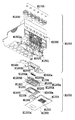
記録ヘッドH1001は、図1の分解斜視図に示すように、記録素子ユニットH1002とタンクホルダーユニットH1003とから構成される。さらに、図2の分解斜視図に示すように、記録素子ユニットH1002は、記録素子基板H1100、第1のプレートH1200、電気配線基板H1300、および第2のプレートH1400で構成されており、また、タンクホルダーユニットH1003は、タンクホルダーH1500、流路形成部材H1600、パッキン部材H200、6個のフィルターH1700、および、6個のシールゴムH1800から構成されている。 As shown in the exploded perspective view of FIG. 1, the recording head H1001 includes a recording element unit H1002 and a tank holder unit H1003. Further, as shown in the exploded perspective view of FIG. 2, the recording element unit H1002 includes a recording element substrate H1100, a first plate H1200, an electric wiring substrate H1300, and a second plate H1400, and a tank. The holder unit H1003 includes a tank holder H1500, a flow path forming member H1600, a packing member H200, six filters H1700, and six seal rubbers H1800.
(記録素子ユニット)
記録素子基板H1100は、例えば、図17に示されるように、サイドシュータタイプとされ、1枚の基板で構成されている。基板において、2列で千鳥掛け状に形成される複数の吐出口H1100Tは、例えば、各インク色ごとに約1200dpi程度に形成されており、異なるインク色のインクをそれぞれ吐出するものとされる。
(Recording element unit)
The recording element substrate H1100 is, for example, a side shooter type as shown in FIG. 17, and is composed of a single substrate. In the substrate, the plurality of ejection openings H1100T formed in two rows in a staggered pattern are formed, for example, at about 1200 dpi for each ink color, and each ejects ink of different ink colors.
記録素子基板H1100は、例えば、その表面に薄膜が形成されているSi基板1101と、基板1101上に形成されるオリフィスプレートH1112とから構成されている。 The recording element substrate H1100 includes, for example, a Si substrate 1101 having a thin film formed on the surface thereof, and an orifice plate H1112 formed on the substrate 1101.
基板1101は、例えば、厚さ0.5〜1(mm)とされ、6色のインク流路として長溝状の貫通口からなるインク供給口H1102が6列互いに平行に一体に形成されている。隣接するインク供給口H1102の相互間距離は、例えば、約2.5mmに設定されている。このように相互間距離が比較的小とされるので記録ヘッドの小型化が図られることとなる。各々のインク供給口H1102の両側には、記録素子としての電気熱変換素子H1103がそれぞれ1列ずつ千鳥状に複数個、例えば、各インク色ごとに約1200dpi程度に配列形成されている。 The substrate 1101 has, for example, a thickness of 0.5 to 1 (mm), and six rows of ink supply ports H1102 each having a long groove-like through-hole as a six-color ink flow path are integrally formed in parallel with each other. The distance between the adjacent ink supply ports H1102 is set to about 2.5 mm, for example. Since the mutual distance is relatively small as described above, the recording head can be reduced in size. On both sides of each ink supply port H1102, a plurality of electrothermal conversion elements H1103 as recording elements are arranged in a zigzag pattern, for example, approximately 1200 dpi for each ink color.
基板1101上に形成される複数の電気熱変換素子H1103および各電気熱変換素子H1103に電力を供給するAl等の電気配線(図17において図示が省略される)は、成膜技術により形成されている。また、その電気配線に電力を供給するための電極部H1104は、電気熱変換素子H1103の配列方向に対して直交する方向の端部に沿って形成されている。電極部H1104は、金等のバンプH1105が複数個、上述の電気配線基板H1300の電極端子H1302にそれぞれ対応して設けられている。インク供給口H1102は、例えば,Si基板1101の結晶方位を利用して、異方性エッチングを行うことにより形成される。 A plurality of electrothermal transducers H1103 formed on the substrate 1101 and electrical wiring such as Al for supplying electric power to each electrothermal transducer H1103 (not shown in FIG. 17) are formed by a film forming technique. Yes. Moreover, the electrode part H1104 for supplying electric power to the electric wiring is formed along the end in the direction orthogonal to the arrangement direction of the electrothermal conversion elements H1103. The electrode portion H1104 is provided with a plurality of bumps H1105 such as gold corresponding to the electrode terminals H1302 of the electric wiring board H1300 described above. The ink supply port H1102 is formed, for example, by performing anisotropic etching using the crystal orientation of the Si substrate 1101.
また、基板H1101上に形成されるオリフィスプレートH1112には、各電気熱変換素子H1103に対応したインク流路を形成するためのインク流路壁H1106と吐出口1100Tとがフォトリソグラフィ技術により形成される。従って、隣接する吐出口1100Tは、互いにインク流路壁H1106により仕切られることとなる。
In addition, in the orifice plate H1112 formed on the substrate H1101, an ink flow path wall H1106 and an
各インク供給口H1102から供給される6色のインクにそれぞれ対応した6列の吐出口H1100T列が一体に1枚のオリフィスプレートH1112に形成されている。吐出口H1100T列は、電気熱変換素子H1103の配列と同様に、千鳥状に複数個、例えば、各インク色ごとに約1200dpi程度に配列形成されている。即ち、吐出口H1100Tは、電気熱変換素子H1103に対向して設けられている。 Six rows of ejection ports H1100T corresponding to the six colors of ink supplied from the respective ink supply ports H1102 are integrally formed in one orifice plate H1112. Similar to the arrangement of the electrothermal conversion elements H1103, the discharge port H1100T array is formed in a staggered manner, for example, about 1200 dpi for each ink color. That is, the discharge port H1100T is provided to face the electrothermal conversion element H1103.
図2に示される第1のプレートH1200は、例えば、厚さ0.5〜10mmのアルミナ(Al2O3)材料で形成されている。なお、第1のプレートの素材は、アルミナに限られることなく、記録素子基板H1100の材料の線膨張率と同等の線膨張率を有し、かつ、記録素子基板H1100材料の熱伝導率と同等もくしは同等以上の熱伝導率を有する材料で作られてもよい。第1のプレートH1200の素材は、例えば、シリコン(Si)、窒化アルミニウム(AlN)、ジルコニア、窒化珪素(Si3N4)、炭化珪素(SiC)、モリブデン(Mo)、タングステン(W)のうちいずれであってもよい。第1のプレートH1200には、記録素子基板H1100に6色のインクを供給するための6つのインク供給口H1201が形成されている。記録素子基板H1100の6つのインク供給口H1102が第1のプレートH1200の6つのインク供給口H1201にそれぞれ対応して位置決めされ、かつ、記録素子基板H1100は第1のプレートH1200に対して位置精度良く接着固定される。接着に用いられる第1の接着剤H1202は、第1のプレートH1200上に略記録素子基板形状で、しかも、隣り合うインク供給口間にエアーパスが発生しないように塗布される。その第1の接着剤H1202は、例えば、粘度が比較的低く、接触面に形成される接着層が薄く、かつ、硬化後、比較的高い硬度を有し、かつ、耐インク性のあるものが望ましい。その第1の接着剤H1202は、例えば、エポキシ樹脂を主成分とした熱硬化接着剤であり、接着層の厚みは50μm以下が望ましい。 The first plate H1200 shown in FIG. 2 is made of, for example, an alumina (Al 2 O 3 ) material having a thickness of 0.5 to 10 mm. The material of the first plate is not limited to alumina, and has a linear expansion coefficient equivalent to that of the material of the recording element substrate H1100 and is equivalent to the thermal conductivity of the material of the recording element substrate H1100. The comb may be made of a material having a thermal conductivity equal to or higher than that. Examples of the material of the first plate H1200 include silicon (Si), aluminum nitride (AlN), zirconia, silicon nitride (Si 3 N 4 ), silicon carbide (SiC), molybdenum (Mo), and tungsten (W). Either may be sufficient. In the first plate H1200, six ink supply ports H1201 for supplying six colors of ink to the recording element substrate H1100 are formed. The six ink supply ports H1102 of the recording element substrate H1100 are positioned corresponding to the six ink supply ports H1201 of the first plate H1200, respectively, and the recording element substrate H1100 has a high positional accuracy with respect to the first plate H1200. Bonded and fixed. The first adhesive H1202 used for bonding is applied on the first plate H1200 in a substantially recording element substrate shape, and so as not to generate an air path between adjacent ink supply ports. The first adhesive H1202, for example, has a relatively low viscosity, a thin adhesive layer formed on the contact surface, a relatively high hardness after curing, and ink resistance. desirable. The first adhesive H1202 is, for example, a thermosetting adhesive mainly composed of an epoxy resin, and the thickness of the adhesive layer is desirably 50 μm or less.
第1のプレートH1200は、突起部H1200Aを両端部にそれぞれ有している。突起部H1200Aは、上述のタンクホルダーH1500の基準端面部H1502aおよび1502bにそれぞれ係合される基準面としての係合面H1200aを有している。突起部H1200Aは、その側面部に対して略垂直に、即ち、タンクホルダーH1500の移動方向に沿って突出している。また、タンクホルダーH1500の位置決めピンIPに対応した位置に、位置決めピンIPの先端が係合される透孔H1200dが形成されている。 The first plate H1200 has protrusions H1200A at both ends. The protrusion H1200A has an engagement surface H1200a as a reference surface that is engaged with the reference end surface portions H1502a and 1502b of the tank holder H1500 described above. The protrusion H1200A protrudes substantially perpendicular to the side surface, that is, along the moving direction of the tank holder H1500. Further, a through hole H1200d with which the tip of the positioning pin IP is engaged is formed at a position corresponding to the positioning pin IP of the tank holder H1500.
電気配線基板H1300は、図2および図17に示されるように、記録素子基板H1100に対してインクを吐出するための電気信号を印加するものであり、記録素子基板H1100を組み込むための開口部H1300aと、記録素子基板H1100の電極部H1104に対応する電極端子H1302と、この配線端部に位置し本体装置からの電気信号を受け取るための外部信号入力端子H1301を有している。 As shown in FIGS. 2 and 17, the electrical wiring board H1300 applies an electrical signal for ejecting ink to the recording element substrate H1100, and has an opening H1300a for incorporating the recording element board H1100. And an electrode terminal H1302 corresponding to the electrode portion H1104 of the recording element substrate H1100 and an external signal input terminal H1301 for receiving an electric signal from the main body device located at the end of the wiring.
電気配線基板H1300の開口部H1300aは、第1のプレートH1200上に配される記録素子基板H1100および第2のプレートH1400の開口部H1400aに対応している。 The opening H1300a of the electrical wiring substrate H1300 corresponds to the opening H1400a of the recording element substrate H1100 and the second plate H1400 disposed on the first plate H1200.
電気配線基板H1300と記録素子基板H1100とは、電気的に接続されている。その接続方法は、例えば、記録素子基板H1100の電極部H1104と電気配線基板H1300の電極端子H1302との間に熱硬化接着樹脂を塗布後、前記記録素子基板H1100の電極部H1104と前記電気配線基板H1300の電極端子H1302とをヒートツールにて一括で加熱加圧されて、熱硬化接着樹脂を硬化させることにより、電極部H1104と電極端子H1302とは電気的に一括接続される。また、熱硬化接着樹脂としては、導電粒子を含んだ異方性導電接着剤を用いた場合も、同様に可能である。本実施例の構成において、例えば、ニッケルの単粒子径が2〜6μmの導電粒子とエポキシ樹脂を主成分とする接着剤で構成される異方性導電接着膜を用いて、記録素子基板H1100の電極部H1104と電気配線基板H1300の金メッキされた電極端子H1302を、温度170〜250℃で加熱圧着したところ、好適に電気接続された。 The electrical wiring substrate H1300 and the recording element substrate H1100 are electrically connected. For example, after the thermosetting adhesive resin is applied between the electrode portion H1104 of the recording element substrate H1100 and the electrode terminal H1302 of the electric wiring substrate H1300, the electrode portion H1104 of the recording element substrate H1100 and the electric wiring substrate are connected. The electrode portion H1104 and the electrode terminal H1302 are collectively connected electrically by heating and pressurizing the electrode terminal H1302 of the H1300 at once with a heat tool to cure the thermosetting adhesive resin. The thermosetting adhesive resin can be similarly used when an anisotropic conductive adhesive containing conductive particles is used. In the configuration of this embodiment, for example, an anisotropic conductive adhesive film composed of conductive particles having a single particle diameter of nickel of 2 to 6 μm and an adhesive mainly composed of an epoxy resin is used to form the recording element substrate H1100. When the electrode part H1104 and the electrode terminal H1302 plated with gold on the electric wiring board H1300 were heat-pressed at a temperature of 170 to 250 ° C., electrical connection was suitably made.
電気配線基板H1300の素材としては、例えば、配線が二層構造のフレキシブル配線基板が使用され、表層はレジストフィルムで覆われている。また、外部信号入力端子H1301の裏面側には、補強板H1303が接着され、外部信号入力端子H1301の平面性を向上させている。補強板H1303の素材としては、例えば0.5〜2mmのガラスエポキシ樹脂、アルミ等の耐熱性のある材料が使用される。 As a material of the electrical wiring board H1300, for example, a flexible wiring board having a two-layer structure is used, and the surface layer is covered with a resist film. In addition, a reinforcing plate H1303 is bonded to the back side of the external signal input terminal H1301 to improve the flatness of the external signal input terminal H1301. As a material of the reinforcing plate H1303, for example, a heat-resistant material such as 0.5 to 2 mm glass epoxy resin or aluminum is used.
第2のプレートH1400は、例えば、厚さ0.5〜1mmのアルミナ(Al2O3)材料で形成されている。なお、第2のプレートの素材は、アルミナに限られることなく、記録素子基板H1100及び第1のプレートH1200と同等の線膨張率を有し、かつ、それらの熱伝導率と同等もしくは同等以上の熱伝導率を有する材料で作られてもよい。そして、第2のプレートH1400は、第1のプレートH1200に接着固定された記録素子基板H1100の外形寸法よりも大きな開口部を有する形状となっている。また、記録素子基板H1100と電気配線基板H1300とを平面的に電気接続できるように、第2のプレートH1400が第1のプレートH1200に第2の接着剤H1203により接着されている。一方、電気配線基板H1300の裏面も、第3の接着剤H1306により第2のプレートH1400に接着固定される。また、電気配線基板H1300は、第2のプレートH1400に接着されると同時に、第1のプレートH1200及び第2のプレートH1400の一側面で折り曲げられ、第1のプレートH1200の側面に第3の接着剤H1306で接着される。第2の接着剤H1203は、例えば、粘度が低く、接触面に形成される接着層が薄く、かつ、耐インク性のあるものが使用される。また、第3の接着剤H1306は、例えば、エポキシ樹脂を主成分とした厚さ10〜100μmの熱硬化接着膜が使用される。 The second plate H1400 is made of, for example, an alumina (Al 2 O 3 ) material having a thickness of 0.5 to 1 mm. The material of the second plate is not limited to alumina, and has a linear expansion coefficient equivalent to that of the recording element substrate H1100 and the first plate H1200, and is equivalent to or higher than their thermal conductivity. It may be made of a material having thermal conductivity. The second plate H1400 has a shape having an opening larger than the outer dimension of the recording element substrate H1100 bonded and fixed to the first plate H1200. Further, the second plate H1400 is bonded to the first plate H1200 with the second adhesive H1203 so that the recording element substrate H1100 and the electric wiring substrate H1300 can be electrically connected in a plane. On the other hand, the back surface of the electric wiring board H1300 is also bonded and fixed to the second plate H1400 by the third adhesive H1306. In addition, the electric wiring board H1300 is bonded to the second plate H1400, and at the same time, is bent on one side of the first plate H1200 and the second plate H1400, and the third bonding is performed on the side of the first plate H1200. Bonded with agent H1306. As the second adhesive H1203, for example, an adhesive having a low viscosity, a thin adhesive layer formed on the contact surface, and having ink resistance is used. Further, as the third adhesive H1306, for example, a thermosetting adhesive film having a thickness of 10 to 100 μm mainly composed of an epoxy resin is used.
以上のように構成された記録素子ユニットH1002の記録素子基板H1100と電気配線基板H1300との電気接続部分は、図1に示されるように、第1の封止剤(不図示)及び第2の封止剤H1308により封止され、電気接続部分をインクによる腐食や外的衝撃から保護している。第1の封止剤は、主に記録素子基板H1100の外周部分を封止し、第2の封止剤は、電気配線基板H1300の開口部のエッジを封止している。また、折り曲げられた電気配線基板H1300は、タンクホルダーH1500の背面形状に合わせて、さらに、フォーミングされる。 As shown in FIG. 1, the electrical connection portion between the recording element substrate H1100 and the electrical wiring substrate H1300 of the recording element unit H1002 configured as described above includes a first sealing agent (not shown) and a second sealing agent. It is sealed with a sealant H1308 to protect the electrical connection portion from ink corrosion and external impact. The first sealing agent mainly seals the outer peripheral portion of the recording element substrate H1100, and the second sealing agent seals the edge of the opening of the electrical wiring substrate H1300. Further, the folded electric wiring board H1300 is further formed in accordance with the back surface shape of the tank holder H1500.
(タンクホルダーユニット)
タンクホルダーH1500は、例えば、樹脂成形により形成される。該樹脂材料には、形状的剛性を向上させるためにガラスフィラーを5〜40%混入した樹脂材料を使用することが望ましい。タンクホルダーH1500は、上述したように、着脱自在のインクタンクH1900を保持するものであり、インクタンクH1900のタンク位置決めピン、第1の爪、第2の爪、第3の爪をそれぞれ係合するタンク位置決め穴1520、第1の穴(不図示)、第2の穴(不図示)、第3の穴1521、及び、インク残量検知に使用するプリズムのための開口部H1506を図1に示されるように有している。
(Tank holder unit)
The tank holder H1500 is formed by resin molding, for example. As the resin material, it is desirable to use a resin material mixed with 5 to 40% of glass filler in order to improve the shape rigidity. As described above, the tank holder H1500 holds the removable ink tank H1900, and engages the tank positioning pin, the first claw, the second claw, and the third claw of the ink tank H1900. FIG. 1 shows a tank positioning hole 1520, a first hole (not shown), a second hole (not shown), a third hole 1521, and an opening H1506 for a prism used for ink remaining amount detection. Have to be.
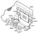
また、タンクホルダーH1500は、記録ヘッドカートリッジH1000をインクジェット記録装置本体のキャリッジM4001に装着位置に案内するための装着ガイドH1507、記録ヘッドカートリッジをヘッドセットレバーによりキャリッジに装着固定するための係合部、及びキャリッジの所定の装着位置に位置決めするためのX突き当て部H1509、Y突き当て部H1510、およびZ突き当て部H1511を備えている。タンクホルダーH1500は、記録素子ユニットH1002の外部信号入力端子H1301部分を位置決め固定する端子固定部H1512を有している。端子固定部H1512及びその周囲には複数のリブが設けられているので、端子固定部H1512を有する面の剛性が高められている。また、各インクタンクH1900が装着される各セル相互間には、各色の混色を防止するリブH1516が設けられている。また、タンクホルダーH1500の側面には、手掛かり部H1513が設けられることにより、記録ヘッドH1001のハンドリング性が向上されている。 The tank holder H1500 includes a mounting guide H1507 for guiding the recording head cartridge H1000 to the mounting position on the carriage M4001 of the ink jet recording apparatus main body, an engaging portion for mounting and fixing the recording head cartridge to the carriage by a head set lever, And an X abutting portion H1509, a Y abutting portion H1510, and a Z abutting portion H1511 for positioning at a predetermined mounting position of the carriage. The tank holder H1500 has a terminal fixing portion H1512 for positioning and fixing the external signal input terminal H1301 portion of the recording element unit H1002. Since a plurality of ribs are provided around the terminal fixing portion H1512 and its periphery, the rigidity of the surface having the terminal fixing portion H1512 is enhanced. Further, a rib H1516 is provided between the cells in which the ink tanks H1900 are mounted to prevent color mixing. Further, a handle portion H1513 is provided on the side surface of the tank holder H1500, so that the handling performance of the recording head H1001 is improved.
また、タンクホルダーH1500は、インクタンクH1900から記録素子ユニットH1002にインクを導くためのインク流路H1501を形成するタンクホルダーユニットH1003の一構成部品である。流路形成部材H1600がタンクホルダーH1500に超音波溶着されることにより、インク流路H1501が形成されている。また、インクタンクH1900と係合するジョイント部には、外部からのゴミの進入を防ぐためのフィルターH1700が熱溶着により接合されており、さらに、ジョイント部H1517からのインクの蒸発を防止するために、シールゴムH1800が装着されている。フィルターH1700は、例えば、空孔径10μm以下のSUS繊維を焼結したフィルターとされ、ドーム状にフォーミングし熱溶着でジョイント部H1518に固定されている。その際、そのドーム状の凸量としては、0.1〜0.5(mm)程度となる最大の曲率半径の形状が好ましい。 The tank holder H1500 is a component of a tank holder unit H1003 that forms an ink flow path H1501 for guiding ink from the ink tank H1900 to the recording element unit H1002. An ink flow path H1501 is formed by ultrasonically welding the flow path forming member H1600 to the tank holder H1500. In addition, a filter H1700 for preventing entry of dust from the outside is joined to the joint portion engaged with the ink tank H1900 by heat welding, and further, in order to prevent ink from evaporating from the joint portion H1517. A seal rubber H1800 is attached. The filter H1700 is, for example, a filter obtained by sintering SUS fibers having a pore diameter of 10 μm or less, formed in a dome shape, and fixed to the joint portion H1518 by heat welding. In that case, as the dome-shaped convex amount, a shape having a maximum curvature radius of about 0.1 to 0.5 (mm) is preferable.
このようなフィルターH1700を設けることにより、外部からの塵の進入に対して効果的であるばかりでなく、各ジョイント部とインクタンクH1900との接続も良好となる。 By providing such a filter H1700, not only is it effective against the entry of dust from the outside, but also the connection between each joint portion and the ink tank H1900 is improved.
タンクホルダーH1500において、流路形成部材H1600が挿入され固定される部分には、図11に示されるように、一端が上述のインク供給孔H1520に連通し、他端が流路形成部材H1600のインク流路の開口端に対応して形成される溝状のインク流路H1521がそれぞれ、各インクタンクH1900に対応して形成されている。従って、各インク流路H1521の他端の相互間隔が、一端の相互間隔に比して小となるように、各インク流路H1521の他端は、流路形成部材H1600のインク流路の開口端に対応して集合している。タンクホルダーH1500における固定される部分に流路形成部材H1600の当接面が接合されることにより、各インクタンクH1900からの各インクをそれぞれ流路形成部材H1600の各インク流路に供給するインク供給路が形成されることとなる。 In the portion of the tank holder H1500 where the flow path forming member H1600 is inserted and fixed, as shown in FIG. 11, one end communicates with the ink supply hole H1520 and the other end is the ink of the flow path forming member H1600. A groove-like ink flow path H1521 formed corresponding to the open end of the flow path is formed corresponding to each ink tank H1900. Therefore, the other end of each ink flow path H1521 is the opening of the ink flow path of the flow path forming member H1600 so that the mutual distance between the other ends of each ink flow path H1521 is smaller than the mutual distance between the one ends. It gathers corresponding to the edge. Ink supply for supplying each ink from each ink tank H1900 to each ink flow path of the flow path forming member H1600 by joining the contact surface of the flow path forming member H1600 to the fixed portion of the tank holder H1500. A path will be formed.
また、流路形成部材H1600が挿入され固定される部分には、流路形成部材H1600および第1のプレートH1200に係合される位置決め用のピンIPが植立されている。 Further, positioning pins IP that are engaged with the flow path forming member H1600 and the first plate H1200 are planted in a portion where the flow path forming member H1600 is inserted and fixed.
さらに、タンクホルダーH1500は、外部信号入力端子H1301が位置決め固定される背面側の下端部に、基準端面部H1502aおよび1502bを有している。基準端面部H1502aおよび1502bは、それぞれ、流路形成部材H1600が挿入され固定される部分の周縁を形成する壁部における同一平面上に形成されている。従って、基準端面部H1502aおよび1502bは、同一平面上に形成されているので成形加工時、同時に成形することが容易となる。 Further, the tank holder H1500 has reference end face portions H1502a and 1502b at the lower end portion on the back side where the external signal input terminal H1301 is positioned and fixed. The reference end face portions H1502a and 1502b are formed on the same plane in the wall portion that forms the periphery of the portion where the flow path forming member H1600 is inserted and fixed. Accordingly, since the reference end face portions H1502a and 1502b are formed on the same plane, it becomes easy to form them simultaneously during the forming process.
また、基準端面部H1502aおよび1502bは、それぞれ、流路形成部材H1600が挿入され固定される部分の周縁に形成される切欠き部H1503aおよびH1503bを通じて側方に連通している。さらに、基準端面部H1502aおよび1502bが形成される壁部の中央には、第1のプレートH1200の端部が係合される切欠部H1504が形成されている。 Further, the reference end face portions H1502a and 1502b are in communication with the sides through notches H1503a and H1503b formed at the periphery of the portion where the flow path forming member H1600 is inserted and fixed, respectively. Further, a notch H1504 with which the end of the first plate H1200 is engaged is formed at the center of the wall where the reference end face portions H1502a and 1502b are formed.
流路形成部材H1600は、パッキン部材H2000を介して組み合わされる第1のプレートH1200に対向する面側に、第1のプレートH1200の両端部を挟持する突起片H1600aおよびH1600bを有している。 The flow path forming member H1600 has projecting pieces H1600a and H1600b that sandwich both end portions of the first plate H1200 on the surface facing the first plate H1200 combined through the packing member H2000.
その際、タンクホルダーH1500に固定された突起片H1600aおよびH1600bとタンクホルダーH1500の基準端面部H1502aおよび1502bとの間には、第1のプレートH1200の突起部H1200Aがそれぞれ係合される所定の隙間が形成されることなる。 At that time, a predetermined gap in which the protrusion H1200A of the first plate H1200 is engaged between the protrusions H1600a and H1600b fixed to the tank holder H1500 and the reference end face portions H1502a and 1502b of the tank holder H1500. Will be formed.
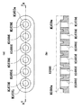
また、相対向する突起片H1600aと突起片H1600bとの間には、図4および図5の(A)および(B)に示されるように、パッキン部材2000のインク流路H2000aおよびH2000b、および、上述の各インク流路H1521の他端にそれぞれ対応して連通孔H1600dが所定の相互間隔で互いに平行に一直線上に形成されている。各連通孔H1600dの開口端部において、パッキン部材H2000が接着剤なしに当接される側の周縁には、円形状の縁H1600eがそれぞれ他の部分に対して隆起して形成されている。各縁H1600eは、パッキン部材H2000と係合されるとき、パッキン部材H2000の各インク流路H2000bに係合するものとされる。即ち、各連通孔H1600dは、パッキン部材H2000を介して第1のプレートH1200内に連通されることとなる。
Further, as shown in FIGS. 4 and 5 (A) and (B), the ink flow paths H2000a and H2000b of the packing
パッキン部材H2000は、ゴム材料、例えば、ガス透過性の低い塩素化ブチルゴムで硬度(JIS K6301 Aスケール)が40度以上〜50度以下となるように作られている。 The packing member H2000 is made of a rubber material, for example, chlorinated butyl rubber having low gas permeability, and has a hardness (JIS K6301 A scale) of 40 degrees to 50 degrees.
本例の場合、パッキン部材H2000は、硬度45度の塩素化ブチルゴムで厚さ約2.5mmに作られている。パッキン部材H2000は、その軸線方向に所定の圧縮力が作用する場合、例えば、図6に示されるように、変位するものとされる。 In the case of this example, the packing member H2000 is made of chlorinated butyl rubber having a hardness of 45 degrees and a thickness of about 2.5 mm. When a predetermined compressive force is applied in the axial direction of the packing member H2000, for example, as shown in FIG. 6, the packing member H2000 is displaced.
図6は、縦軸に反発力σ(N)、横軸に圧縮量δ(mm)をとり、圧縮量δに応じた反発力σの特性を示す。反発力σは、圧縮量δが増大するにつれた所定の勾配で比例して増大し、反発力σが10(N)、圧縮量δが0.5mmを越えるとき、反発力σは、圧縮量δの増大に応じてさらに大きな勾配で増大するものとされる。流路形成部材H1600と第1のプレートH1200との間に作用するパッキン部材H2000の当接圧を設定するにあたっては、上述の硬度45度の塩素化ブチルゴムと第1のプレートH1200及び流路形成部材H1600の密着性について検証を行い決定された。 FIG. 6 shows the characteristic of the repulsive force σ according to the compression amount δ, with the vertical axis representing the repulsive force σ (N) and the horizontal axis representing the compression amount δ (mm). The repulsive force σ increases in proportion to a predetermined gradient as the compression amount δ increases. When the repulsive force σ is 10 (N) and the compression amount δ exceeds 0.5 mm, the repulsive force σ is It is assumed that it increases with a larger gradient as δ increases. In setting the contact pressure of the packing member H2000 acting between the flow path forming member H1600 and the first plate H1200, the chlorinated butyl rubber having the hardness of 45 degrees, the first plate H1200, and the flow path forming member are set. It was determined by examining the adhesion of H1600.
なお、その検証方法としては、パッキン部材H2000が実際に上述の記録ヘッドカートリッジH1000の構成部品として組付けられた後、所定の負圧による吸引動作に基づくリークテストおよび、その相互間の接着性が目視により確認された。図1に示される流路形成部材H1600の所定位置に塗布される接着剤は、エポキシ系接着剤(商品名HP−2R/2H、キヤノン化成社製)が使用された。その結果、図6に示される特性のパッキン部材H2000において、当接圧(反発力σ)が5(N)から10(N)の範囲で、リークテストおよび、その接着性について問題は生じなかった。 As a verification method, after the packing member H2000 is actually assembled as a component of the above-described recording head cartridge H1000, there is a leak test based on a suction operation with a predetermined negative pressure and adhesion between them. It was confirmed visually. An epoxy adhesive (trade name HP-2R / 2H, manufactured by Canon Kasei Co., Ltd.) was used as the adhesive applied to a predetermined position of the flow path forming member H1600 shown in FIG. As a result, in the packing member H2000 having the characteristics shown in FIG. 6, when the contact pressure (repulsive force σ) was in the range of 5 (N) to 10 (N), there was no problem with the leak test and its adhesion. .
また、接着する部位を後述の表面処理を行った場合、後述の各接着剤の接着力の向上が確認されており、パッキン部材H2000の反発力σが30(N)の場合においても接着が可能であった。 In addition, when the surface treatment described below is performed on the part to be bonded, it has been confirmed that the adhesive force of each adhesive described later has been improved, and bonding is possible even when the repulsive force σ of the packing member H2000 is 30 (N). Met.
これは、第1のプレート部材H1200を流路形成部材H1600から引き離す方向に作用されるその弾性力とそれと同一方向に作用する電気配線基板H1300の弾性力との和がその接着剤の接着力よりも小となるからである。 This is because the sum of the elastic force acting in the direction of separating the first plate member H1200 from the flow path forming member H1600 and the elastic force of the electric wiring board H1300 acting in the same direction is based on the adhesive force of the adhesive. Because it becomes small.
従って、パッキン部材H2000の反発力σは5(N)以上30(N)以下、好ましくは、5(N)以上10(N)以下の範囲に設定される。 Therefore, the repulsive force σ of the packing member H2000 is set in the range of 5 (N) to 30 (N), preferably 5 (N) to 10 (N).
本例では、パッキン部材H2000が流路形成部材H1600と第1のプレートH1200との間に配されるとき、パッキン部材H2000の当接圧(反発力σ)が好適に作用させるため、その圧縮量δが0.3mm以上0.5mm以下となるように設定されている。 In this example, when the packing member H2000 is disposed between the flow path forming member H1600 and the first plate H1200, the contact pressure (repulsive force σ) of the packing member H2000 preferably acts. δ is set to be 0.3 mm or more and 0.5 mm or less.
従って、図6から明らかなように、パッキン部材H2000により、5(N)以上10(N)以下の反力が流路形成部材H1600と第1のプレートH1200との間に作用することとなる。 Therefore, as is apparent from FIG. 6, the packing member H2000 causes a reaction force of 5 (N) or more and 10 (N) or less to act between the flow path forming member H1600 and the first plate H1200.
パッキン部材H2000は、流路形成部材H1600の各縁H1600eがそれぞれ嵌合されるインク流路H2000bを6個有している。また、そのインク流路H2000bは、その内径よりも小なる内径を有するインク流路H2000aに連なり連通している。インク流路H2000bの開口端部の周縁には、流路形成部材H1600の各縁H1600eの周囲を形成する平坦面に当接する環状のリップ部H2000pが形成されている。一方、インク流路H2000aの開口端部の周縁には、第1のプレートH1200の表面に当接する環状のリブ部H2000rが形成されている。従って、パッキン部材H2000は、第1のプレートH1200の表面に対しリブ部H2000rのみを介して接触することとなる。 The packing member H2000 has six ink flow paths H2000b into which the respective edges H1600e of the flow path forming member H1600 are fitted. The ink flow path H2000b is connected to and communicates with an ink flow path H2000a having an inner diameter smaller than the inner diameter. An annular lip portion H2000p that abuts on a flat surface that forms the periphery of each edge H1600e of the flow path forming member H1600 is formed at the periphery of the opening end of the ink flow path H2000b. On the other hand, an annular rib portion H2000r that is in contact with the surface of the first plate H1200 is formed at the periphery of the opening end of the ink flow path H2000a. Accordingly, the packing member H2000 comes into contact with the surface of the first plate H1200 only through the rib portion H2000r.
リブ部H2000rは、例えば、幅W、高さHがそれぞれ、0.3mm、0.15mmとされる三角形の断面形状を有している。 For example, the rib portion H2000r has a triangular cross-sectional shape in which the width W and the height H are 0.3 mm and 0.15 mm, respectively.
(記録ヘッドユニットとタンクホルダーユニットとの結合)
先述した通り、記録ヘッドH1001は、図3に示されるように、記録素子ユニットH1002がタンクホルダーユニットH1003に結合されることにより完成する。結合は以下のように行われる。
(Combination of recording head unit and tank holder unit)
As described above, the recording head H1001 is completed by connecting the recording element unit H1002 to the tank holder unit H1003 as shown in FIG. The coupling is performed as follows.
記録素子ユニットH1002のインク供給口(第1のプレートH1200のインク供給口H1201)とタンクホルダーユニットH1003のインク供給口(流路形成部材H1600のインク供給口)とをパッキン部材H2000を介して連通させるように第7の接着剤H1605を、図1に示されるように、流路形成部材H1600の複数の箇所に塗布し、第1のプレートH1200と流路形成部材H1600とが接着固定される。第7の接着剤H1605は、例えば、上述したエポキシ系接着剤(商品名HP−2R/2H、キヤノン化成社製)が使用された。第7の接着剤H1605の接着力は、例えば、30(N)以上とされる。 The ink supply port of the recording element unit H1002 (ink supply port H1201 of the first plate H1200) and the ink supply port of the tank holder unit H1003 (ink supply port of the flow path forming member H1600) are communicated via the packing member H2000. As shown in FIG. 1, the seventh adhesive H1605 is applied to a plurality of locations on the flow path forming member H1600, and the first plate H1200 and the flow path forming member H1600 are bonded and fixed. As the seventh adhesive H1605, for example, the above-described epoxy adhesive (trade name HP-2R / 2H, manufactured by Canon Kasei Co., Ltd.) was used. The adhesive force of the seventh adhesive H1605 is, for example, 30 (N) or more.
従って、上述したように、パッキン部材H2000の反発力が5N以上10N以下とされ、それと同一方向に作用される電気配線基板H1300の弾性力が15(N)程度とされるので第1のプレートH1200と流路形成部材H1600とは第7の接着剤H1605により確実に接着されることとなる。 Therefore, as described above, the repulsive force of the packing member H2000 is 5N or more and 10N or less, and the elastic force of the electric wiring board H1300 acting in the same direction is about 15 (N), so the first plate H1200. And the flow path forming member H1600 are securely bonded by the seventh adhesive H1605.
また、記録素子ユニットH1002をタンクホルダーユニットH1003に第7の接着剤H1605で接着する際に、記録素子ユニットH1002は、図1に示される流路形成部材H1600の所定箇所に塗布される第6の接着剤H1604で位置決め仮固定される。第6の接着剤H1604は、瞬時に硬化する接着剤が望ましく、本実施例においては、例えば、紫外線硬化接着剤を使用しているが、他の接着剤でも構わない。 Further, when the recording element unit H1002 is bonded to the tank holder unit H1003 by the seventh adhesive H1605, the recording element unit H1002 is applied to a predetermined portion of the flow path forming member H1600 shown in FIG. Positioning is temporarily fixed with an adhesive H1604. The sixth adhesive H1604 is desirably an adhesive that cures instantaneously. In this embodiment, for example, an ultraviolet curable adhesive is used, but another adhesive may be used.
第7の接着剤H1605は、耐インク性があり、かつ、常温で硬化し、かつ、異種材料間の線膨張差に耐えられる柔軟性のあるいずれの接着剤であってもよい。 The seventh adhesive H1605 may be any adhesive that has ink resistance, is cured at room temperature, and is flexible enough to withstand the difference in linear expansion between different materials.
記録素子ユニットH1002の外部信号入力端子H1301部分は、タンクホルダーH1500の一側面に、端子位置決めピンH1515(2ケ所)と端子位置決め穴H1309(2ケ所)とにより位置決めされ、固定される。固定方法は、例えば、タンクホルダーH1500に設けられた端子結合ピンH1516(6箇所)と、電気配線基板H1300の外部信号入力端子H1301周辺に設けられた端子結合穴H1310(6箇所)とをはめ合わされ、端子結合ピンH1516を熱溶着することにより固定しているが、その他の固定手段を用いても良い。 The external signal input terminal H1301 portion of the recording element unit H1002 is positioned and fixed to one side surface of the tank holder H1500 by terminal positioning pins H1515 (two places) and terminal positioning holes H1309 (two places). For example, the terminal coupling pins H1516 (six locations) provided in the tank holder H1500 and the terminal coupling holes H1310 (six locations) provided around the external signal input terminal H1301 of the electric wiring board H1300 are fitted together. The terminal coupling pin H1516 is fixed by heat welding, but other fixing means may be used.
その際、第6の接着剤H1604の接着力は、第7の接着剤H1605の接着力に比して小である20(N)程度とされるので図7に示される板ばねとされる保持部材H2100により、所定期間、例えば、約12時間、第1のプレートH1200が流路形成部材H1600に対して保持される。 At this time, since the adhesive force of the sixth adhesive H1604 is about 20 (N), which is smaller than the adhesive force of the seventh adhesive H1605, the holding as the leaf spring shown in FIG. The member H2100 holds the first plate H1200 against the flow path forming member H1600 for a predetermined period, for example, about 12 hours.
保持部材H2100は、図7に示されるように、タンクホルダーH1500に固定された電気配線基板H1300の両側部にそれぞれ係止される二股状の第1の係止部H1200aと、タンクホルダーH1500の略中央部分の隣接するふたつの開口部H1506内に挿入されて係合される第2の係止部H2100cと、第1の係止部H1200aと第2の係止部H2100cとを連結するとともに、電気配線基板H1300における記録素子H1100の周囲を押圧する押圧部H2100dとから構成されている。 As shown in FIG. 7, the holding member H2100 includes a bifurcated first locking portion H1200a that is locked to both sides of the electric wiring board H1300 fixed to the tank holder H1500, and an abbreviation of the tank holder H1500. The second locking portion H2100c inserted into and engaged with two adjacent openings H1506 in the central portion, the first locking portion H1200a, and the second locking portion H2100c are coupled, The wiring board H1300 includes a pressing portion H2100d that presses the periphery of the recording element H1100.
保持部材H2100は、第1のプレートH1200が流路形成部材H1600から引き離される方向、即ち、矢印の示す方向に作用される付勢力に抗して第1のプレートH1200の接着状態を維持するものとされる。保持部材H2100は、その付勢力が約50以上100(N)以下の範囲にある場合、第1のプレートH1200の接着状態を維持するものとされる。 The holding member H2100 maintains the adhesive state of the first plate H1200 against the urging force acting in the direction in which the first plate H1200 is separated from the flow path forming member H1600, that is, the direction indicated by the arrow. Is done. The holding member H2100 maintains the adhesion state of the first plate H1200 when the urging force is in the range of about 50 or more and 100 (N) or less.
従って、記録素子ユニットH1002がタンクホルダーユニットH1003に結合されるにあたり、記録素子ユニットH1002のインク供給口(第1のプレートH1200のインク供給口H1201)とタンクホルダーユニットH1003のインク供給口(流路形成部材H1600のインク供給口)とが接着剤なしにパッキング部材H2000を介して結合されるのでその塗布量を管理するといった品質管理が不要とされ、記録ヘッドを迅速にかつ容易に組立てることができる。 Accordingly, when the recording element unit H1002 is coupled to the tank holder unit H1003, the ink supply port of the recording element unit H1002 (ink supply port H1201 of the first plate H1200) and the ink supply port of the tank holder unit H1003 (flow path formation). Since the ink supply port of the member H1600 is coupled to the member H1600 via the packing member H2000 without an adhesive, the quality control of managing the coating amount is unnecessary, and the recording head can be assembled quickly and easily.
上述の例において、さらに、タンクホルダーH1500の各被接着面が結合される前に、その各被接着面に対し改質処理が施されても良い。改質処理としては、酸素プラズマ、または、コロナ放電処理が好ましい。本例においては、高周波コロナ表面処理装置(AGI−02S,300W,春日電機社製)で約30秒間処理された。コロナ放電処理とは、空気中に設置した電極間に高周波、高電圧を印加し発生する電子を、その電極間に配されるワークの表面に衝突させることにより、その表面に活性基が発生し接着力が高められる処理をいう。 In the above-described example, before the surfaces to be bonded of the tank holder H1500 are joined, the surface to be bonded may be subjected to a modification process. As the modification treatment, oxygen plasma or corona discharge treatment is preferable. In this example, it was processed for about 30 seconds with a high-frequency corona surface treatment apparatus (AGI-02S, 300W, manufactured by Kasuga Denki Co., Ltd.). In the corona discharge treatment, an active group is generated on the surface of the work piece placed between the electrodes by colliding the electrons generated by applying high frequency and high voltage between the electrodes installed in the air. This is a process that increases the adhesive strength.
これにより、上述の第6の接着剤H1604の接着力が約50(N)まで高められ、第7の接着剤H1605の接着力が約200(N)まで高められた。 Thereby, the adhesive force of the sixth adhesive H1604 described above was increased to about 50 (N), and the adhesive force of the seventh adhesive H1605 was increased to about 200 (N).
従って、このように結合前に改質処理がなされることにより、上述のような保持部材H2100が不要とされることとなる。その結果、製造において、量産性が向上することとなる。 Therefore, the above-described holding member H2100 is not required by performing the reforming process before the coupling as described above. As a result, mass productivity is improved in production.
H1000 記録ヘッドカートリッジ
H1001 記録ヘッド
H1100 記録素子基板
H1100T 吐出口
H1200 第1のプレート
H1201 インク供給口
H1300 電気配線基板
H1301 外部信号入力端子
H1400 第2のプレート
H1500 タンクホルダー
H1501 インク流路
H1600 流路形成部材
H1700 フィルター
H1800 シールゴム
H1900 インクタンク
H1600d 連通路
H2000 パッキン部材
H1000 recording head cartridge H1001 recording head H1100 recording element substrate H1100T discharge port H1200 first plate H1201 ink supply port H1300 electric wiring substrate H1301 external signal input terminal H1400 second plate H1500 tank holder H1501 ink flow path H1600 flow path forming member H1700 Filter H1800 Seal rubber H1900 Ink tank H1600d Communication path H2000 Packing member
Claims (3)
前記板状部材の前記液体供給路の一方の端部と、前記液体供給ユニット部の前記連通路の一方の端部との間に、該液体供給路および該連通路に連通する液体流路を有する弾性シール部材を配する工程と、
前記液体供給ユニット部と前記記録素子ユニットを、前記弾性シール部材が圧縮された状態で該弾性シール部材の周囲を形成する接合面における複数箇所に塗布される所定の硬化時間で硬化する紫外線硬化型接着剤により仮固定した後、該接合面における他の複数箇所に塗布され、該紫外線硬化型接着剤の接着力よりも接着力が強く常温で前記所定の硬化時間より長い時間で硬化する接着剤により接着し固定する工程と、
を有することを特徴とする液体吐出記録ヘッドの製造方法。 A recording element unit that includes a recording element substrate that discharges liquid and performs a recording operation; a plate-like member having a liquid supply path that supplies liquid to the recording element substrate; and a liquid from a liquid supply source that supplies liquid. A liquid supply recording unit having a communication path leading to the recording element unit;
A liquid flow path communicating with the liquid supply path and the communication path between one end of the liquid supply path of the plate-like member and one end of the communication path of the liquid supply unit; Arranging an elastic seal member having;
An ultraviolet curable type in which the liquid supply unit and the recording element unit are cured in a predetermined curing time applied to a plurality of locations on a joint surface that forms the periphery of the elastic seal member in a state where the elastic seal member is compressed. An adhesive that is temporarily fixed with an adhesive and then applied to a plurality of other locations on the joint surface, and has an adhesive strength stronger than that of the ultraviolet curable adhesive and cures at room temperature for a time longer than the predetermined curing time. Bonding and fixing by,
A method of manufacturing a liquid discharge recording head, comprising:
Priority Applications (1)
| Application Number | Priority Date | Filing Date | Title |
|---|---|---|---|
| JP2009212157A JP4781462B2 (en) | 2009-09-14 | 2009-09-14 | Manufacturing method of liquid discharge recording head |
Applications Claiming Priority (1)
| Application Number | Priority Date | Filing Date | Title |
|---|---|---|---|
| JP2009212157A JP4781462B2 (en) | 2009-09-14 | 2009-09-14 | Manufacturing method of liquid discharge recording head |
Related Parent Applications (1)
| Application Number | Title | Priority Date | Filing Date |
|---|---|---|---|
| JP2000209106A Division JP4444462B2 (en) | 2000-07-10 | 2000-07-10 | Liquid discharge recording head and recording apparatus including the same |
Publications (2)
| Publication Number | Publication Date |
|---|---|
| JP2010018030A true JP2010018030A (en) | 2010-01-28 |
| JP4781462B2 JP4781462B2 (en) | 2011-09-28 |
Family
ID=41703378
Family Applications (1)
| Application Number | Title | Priority Date | Filing Date |
|---|---|---|---|
| JP2009212157A Expired - Fee Related JP4781462B2 (en) | 2009-09-14 | 2009-09-14 | Manufacturing method of liquid discharge recording head |
Country Status (1)
| Country | Link |
|---|---|
| JP (1) | JP4781462B2 (en) |
Cited By (2)
| Publication number | Priority date | Publication date | Assignee | Title |
|---|---|---|---|---|
| JP2013248802A (en) * | 2012-05-31 | 2013-12-12 | Canon Inc | Liquid discharge head and liquid discharge apparatus |
| JP2021088140A (en) * | 2019-12-05 | 2021-06-10 | キヤノン株式会社 | Liquid discharge head |
Citations (2)
| Publication number | Priority date | Publication date | Assignee | Title |
|---|---|---|---|---|
| JPH10119314A (en) * | 1996-08-30 | 1998-05-12 | Canon Inc | Method for connecting liquid discharge head unit, the head unit, and liquid discharge cartridge |
| JPH11147314A (en) * | 1997-11-17 | 1999-06-02 | Canon Inc | Ink-jet recording head and ink-jet recording apparatus |
-
2009
- 2009-09-14 JP JP2009212157A patent/JP4781462B2/en not_active Expired - Fee Related
Patent Citations (2)
| Publication number | Priority date | Publication date | Assignee | Title |
|---|---|---|---|---|
| JPH10119314A (en) * | 1996-08-30 | 1998-05-12 | Canon Inc | Method for connecting liquid discharge head unit, the head unit, and liquid discharge cartridge |
| JPH11147314A (en) * | 1997-11-17 | 1999-06-02 | Canon Inc | Ink-jet recording head and ink-jet recording apparatus |
Cited By (3)
| Publication number | Priority date | Publication date | Assignee | Title |
|---|---|---|---|---|
| JP2013248802A (en) * | 2012-05-31 | 2013-12-12 | Canon Inc | Liquid discharge head and liquid discharge apparatus |
| JP2021088140A (en) * | 2019-12-05 | 2021-06-10 | キヤノン株式会社 | Liquid discharge head |
| JP7467090B2 (en) | 2019-12-05 | 2024-04-15 | キヤノン株式会社 | Liquid ejection head |
Also Published As
| Publication number | Publication date |
|---|---|
| JP4781462B2 (en) | 2011-09-28 |
Similar Documents
| Publication | Publication Date | Title |
|---|---|---|
| EP1078760B1 (en) | Print head and ink jet printing apparatus | |
| EP1078759B1 (en) | Liquid ejection type print head, printing apparatus provided with same and a method for producing a liquid ejection type print head | |
| JP3897490B2 (en) | Coated rubber member, recording head, storage box, and ink jet recording apparatus | |
| KR100615006B1 (en) | Ink jet printing method and apparatus | |
| JP4646665B2 (en) | Inkjet recording head | |
| JP4880926B2 (en) | Recording device | |
| JP2002019117A (en) | Substrate for ink jet recording head, ink jet recording head, ink jet cartridge, and ink jet recording apparatus | |
| JP2007283501A (en) | Inkjet recording head | |
| JP2002026471A (en) | Flexible printed wiring board, liquid spray head using the same, head cartridge and image forming apparatus | |
| JP2002079675A (en) | Liquid discharge head, its manufacturing method, head cartridge, and imaging apparatus | |
| JP4781462B2 (en) | Manufacturing method of liquid discharge recording head | |
| JP2001138520A (en) | Recording head, method of manufacturing the same and ink jet recording apparatus | |
| JP4444462B2 (en) | Liquid discharge recording head and recording apparatus including the same | |
| JP4261745B2 (en) | Liquid discharge recording head cartridge and recording apparatus | |
| JP2007055090A (en) | Inkjet recording head | |
| JP4497678B2 (en) | Liquid discharge recording head and recording apparatus including the same | |
| JP2001130005A (en) | Liquid ejection head and method for driving it and cartridge and imaging apparatus | |
| JP4298350B2 (en) | RECORDING HEAD SUBSTRATE, LIQUID DISCHARGE RECORDING HEAD HAVING THE SAME, RECORDING DEVICE, AND METHOD FOR PRODUCING RECORDING HEAD SUBSTRATE | |
| JP3382566B2 (en) | Protective member for recording head | |
| JP4683588B2 (en) | Liquid discharge recording head and liquid discharge recording apparatus | |
| JP2001063053A (en) | Recording head, electric wiring board and recording apparatus equipped with them | |
| JP2001058417A (en) | Ink tank, recording head cartridge and ink-jet recording apparatus | |
| JP2002019121A (en) | Ink jet recording head and its manufacturing method | |
| JP2002029056A (en) | Liquid discharge head, head cartridge using the same, and image-forming apparatus | |
| JP2007313667A (en) | Liquid jet recording head |
Legal Events
| Date | Code | Title | Description |
|---|---|---|---|
| RD02 | Notification of acceptance of power of attorney |
Free format text: JAPANESE INTERMEDIATE CODE: A7422 Effective date: 20101106 |
|
| TRDD | Decision of grant or rejection written | ||
| A01 | Written decision to grant a patent or to grant a registration (utility model) |
Free format text: JAPANESE INTERMEDIATE CODE: A01 Effective date: 20110701 |
|
| A01 | Written decision to grant a patent or to grant a registration (utility model) |
Free format text: JAPANESE INTERMEDIATE CODE: A01 |
|
| A61 | First payment of annual fees (during grant procedure) |
Free format text: JAPANESE INTERMEDIATE CODE: A61 Effective date: 20110705 |
|
| FPAY | Renewal fee payment (event date is renewal date of database) |
Free format text: PAYMENT UNTIL: 20140715 Year of fee payment: 3 |
|
| FPAY | Renewal fee payment (event date is renewal date of database) |
Free format text: PAYMENT UNTIL: 20140715 Year of fee payment: 3 |
|
| LAPS | Cancellation because of no payment of annual fees |