JP4497678B2 - Liquid discharge recording head and recording apparatus including the same - Google Patents
Liquid discharge recording head and recording apparatus including the same Download PDFInfo
- Publication number
- JP4497678B2 JP4497678B2 JP2000254461A JP2000254461A JP4497678B2 JP 4497678 B2 JP4497678 B2 JP 4497678B2 JP 2000254461 A JP2000254461 A JP 2000254461A JP 2000254461 A JP2000254461 A JP 2000254461A JP 4497678 B2 JP4497678 B2 JP 4497678B2
- Authority
- JP
- Japan
- Prior art keywords
- recording
- holder
- recording element
- ink
- recording head
- Prior art date
- Legal status (The legal status is an assumption and is not a legal conclusion. Google has not performed a legal analysis and makes no representation as to the accuracy of the status listed.)
- Expired - Fee Related
Links
Images


Landscapes
- Ink Jet (AREA)
Description
【0001】
【発明の属する技術分野】
本発明は、液体吐出記録ヘッド、および、それを備える記録装置に関する。なお、本発明は、一般的なプリント装置のほか、複写機、通信システムを有するファクシミリ,プリント部を有するワードプロセッサ等の装置、さらには、各種処理装置と複合的に組み合わされた産業用記録装置に適用することができる。
【0002】
【従来の技術】
記録媒体の記録面に対して記録動作を行う記録装置としてインクジェット記録装置が実用に供されている。インクジェット記録装置は、一般に,例えば、図22および23にも示されるように,インクを記録媒体の記録面に対して吐出する記録ヘッドを有するインクカートリッジを備えている。
【0003】
インクカートリッジは、図22および図23に示されるように,所定の色のインク、例えば、イエロー、マゼンタ、および、シアンのインクをそれぞれ貯留するインクタンク4Y,4M,および、4Cと、インクタンク4Y〜4Cを収容するホルダー2と、ホルダー2の底部に設けられ各インクタンク4Y〜4Cからのインクを複数の吐出口を通じて吐出する記録素子基板10と、記録素子基板10に電気的に接続され記録素子基板10に制御信号群を供給するフレキシブル配線基板8とを含んで構成されている。
【0004】
記録素子基板10は、各色のインクをそれぞれ吐出する基板10C,10M,および、10Yから構成されている。基板10C,10M,および、10Yは、互いに同一構成とされるので基板10Mについて説明し、他の基板についての説明を省略する。
【0005】
基板10Mは、例えば、図21に拡大されて示されるように、シリコンで薄板状に作られ、一方向に沿って千鳥掛け状に形成されるインク吐出口群10aを長手方向に沿って有している。各インク吐出口に通じる各インク流路には、それぞれ電気熱変換体としてのヒータが設けられている。また、その両端部の短辺には、それぞれ、供給される制御信号を図示が省略される導体層を介してそれぞれその各ヒータに供給する電極群10eが形成されている。基板10Mの裏面側には、インク吐出口群10aに対応して細長い凹部10bが形成されている。
【0006】
樹脂材料で作られるホルダー2の底部における隆起部分には、その中央に開口部を有するフレーム部材12が設けられている。そのフレーム部材12の開口部には、支持部材14が配されている。支持部材14は、記録素子基板10が駆動時に発する熱を放熱する役目とともに、その配される基板10Y〜10C取付け面に対して互いに平行にする役割を果たすものとされる。フレーム部材12は、支持部材14に接着固定されるため支持部材14と同様に放熱部材としての役目がある。支持部材14およびフレーム部材12は、例えば,記録素子基板10の材料と同等な平面度の加工精度が比較的高精度に得られ、かつ、放熱性に優れたシリコンまたはアルミナなどにより形成されている。支持部材14は、その中央部に各インクタンクからのインクがそれぞれ通過せしめられるインク供給口14aを所定の間隔をもって3箇所に有しており、ホルダー2に接着固定されている。接着剤としては、例えば、封止剤をかねた耐インク性があり、アルミナと樹脂材料との間などの異種材料間の線膨張係数差を補える弾力性のあるシリコン変性エポキシ系接着剤が利用される。
【0007】
ホルダー部材としてのホルダー2の底部における隆起部分の両端部には、それぞれ凹部2Aが設けられている。各凹部2Aは、4つの平坦面に囲まれて形成されている。その4つの面のうちの一つである基準面2RSが、インクタンク4Y〜4Cを伴って移動せしめられるホルダー2の移動方向、即ち、図21の矢印Sの示す方向に沿って形成されている。各凹部2Aの各基準面2RSは、後述するキャリッジ部材16の係合部16Kにそれぞれ係合される。
【0008】
さらに、フレーム部材12上には、図22に示されるように、各記録素子基板10の基板10C〜10Yの電極群10eに電気的に接続されるフレキシブル配線基板8が配されている。フレキシブル配線基板8は、記録素子基板10に対応する位置に開口部を有している。
【0009】
インクタンク4Y〜4Cが収容されるホルダー2は、図23に二点鎖線で示されるように矢印の示す方向に沿ってキャリッジ部材6内に挿入され、記録装置に備えられるキャリッジ部材16内の被装着部に実線で示されるように装着される。
【0010】
キャリッジ部材16は、その基端部の透孔16bにガイドシャフトGSが摺動可能に嵌合されることにより移動可能に支持されている。また、キャリッジ部材16の底部には、その被装着部に連通する開口部16aが形成されている。さらに、開口部16aの周縁には、相対向して上述ホルダー2の凹部2Aの基準面2RSが係合される被係合面を有する係合部16Kが設けられている。係合部16Kは、図23の矢印Sの示す方向、即ち、キャリッジ部材16の移動方向に沿って開口部16a内に突出している。
【0011】
矢印Sの示す方向に移動しつつ、記録媒体の記録面における所定位置に画素を形成するにあたり、上述したような記録素子基板10のインク吐出口群10aは、図21および図23の矢印Sの示す方向に対して所定の角度、例えば、略直交する方向に位置決めされていることが必要とされる。
【0012】
従って、記録素子基板10をホルダー2における所定位置に位置決め固定するにあたっては、先ず、各基板10Y〜10Cのインク吐出口群10aの方向が基準面2RSに対して略直交する方向となるように記録素子基板10がフレーム部材12の開口部内の支持部材14上に位置決めされ、接着により固定される。接着剤としては、例えば,封止剤をかねた耐インク性のあるエポキシ系の熱硬化型接着剤が利用される。これにより、記録素子基板10は、そのインク吐出口群10aがホルダー2において基準面2RSに対して略直交する方向に延びるように固定されることとなる。
【0013】
次に、ホルダー2における記録素子基板10のインク吐出口群10aをキャリッジ部材の被装着部の所定位置に対して位置決めするに当たっては、図23に示されるように、ホルダー2は、凹部2A内の基準面2RSが係合部16Kの係合面に当接するようにその被装着部内に挿入配置されることにより、装着された記録素子基板10のインク吐出口群10aの位置は、自動的に矢印Sの示す方向に対して略直交する方向に位置決めされることとなる。
【0014】
【発明が解決しようとする課題】
しかしながら、上述のように,記録素子基板10のホルダー2における支持部材14に対する位置決めと、記録素子基板10のホルダー2を介し間接的にキャリッジ部材16に対する位置決めとが互いに異なる基準面に基づいて行われるので結果的に記録素子基板10のキャリッジ部材16に対する位置決め誤差が累積することとなる。従って、記録素子基板10の位置決め精度が低下する虞がある。
【0015】
本発明は、キャリッジ部材に対する記録素子基板の位置決め精度を簡易な機構で向上させることができる液体吐出記録ヘッド、および、それを備える記録装置を提供することを主たる目的とする。
【0016】
【課題を解決するための手段】
上述の目的を達成するために、本発明に係る液体吐出記録ヘッドは、液体を吐出するための記録素子を有する複数の記録素子基板と、記録素子基板を支持する支持体と、支持体を保持するホルダーであって、ホルダーを伴なって移動するキャリッジおよび該ホルダー相互間の位置決めを行う位置決め部を備えるホルダーと、を具備する液体吐出記録ヘッドであって、ホルダーにおける位置決め部は、支持体およびホルダー相互間の位置決めを行う位置決め部をかねていることを特徴とする。
【0017】
また、本発明に係る記録装置は、液体を吐出して記録を行う液体吐出記録ヘッドと、液体吐出記録ヘッドを装着して移動するキャリッジと、を備える記録装置において、液体吐出記録ヘッドは、液体を吐出するための記録素子を有する複数の記録素子基板と、記録素子基板を支持する支持体と、支持体を保持するホルダーであって、ホルダーを伴なって移動するキャリッジおよびホルダー相互間の位置決めを行う位置決め部を備えるホルダーと、を具備し、ホルダーにおける位置決め部は、支持体およびホルダー相互間の位置決めを行う位置決め部をかねていることを特徴とする。
【0019】
【発明の実施の形態】
以下、図面を参照して本発明に係る液体吐出記録ヘッドを備える記録装置に係る実施形態を説明する。
【0020】
なお、以下に説明する実施形態では、インクジェット記録方式を用いた記録装置としてプリンタを例に挙げ説明する。
【0021】
そして、本明細書において、「プリント」(「記録」という場合もある)とは、文字、図形等有意の情報を形成する場合のみならず、有意無意を問わず、また人間が視覚で知覚し得るように顕在化したものであるか否かを問わず、広くプリント媒体上に画像、模様、パターン等を形成する、または媒体の加工を行う場合も言うものとする。
【0022】
ここで、「プリント媒体」とは、一般的なプリント装置で用いられる紙のみならず、広く、布、プラスチック・フィルム、金属板等、ガラス、セラミックス、木材、皮革等、インクを受容可能な物も言うものとする。
【0023】
さらに、「インク」(「液体」という場合もある)とは、上記「プリント」の定義と同様広く解釈されるべきもので、プリント媒体上に付与されることによって、画像、模様、パターン等の形成またはプリント媒体の加工、或いはインクの処理(例えばプリント媒体に付与されるインク中の色材の凝固または不溶化)に供され得る液体を言うものとする。
【0024】
[装置本体]
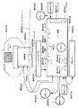
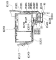
図1及び図2にインクジェット記録方式を用いたプリンタの概略構成を示す。図1において、この実施形態におけるプリンタの装置本体M1000の外郭は、下ケースM1001、上ケースM1002、アクセスカバーM1003及び排出トレイM1004を含む外装部材と、その外装部材内に収納されたシャーシM3019(図2参照)とから構成される。
【0025】
シャーシM3019は、所定の剛性を有する複数の板状金属部材によって構成され、記録装置の骨格をなし、後述の各記録動作機構を保持するものとなっている。
また、前記下ケースM1001は装置本体M1000の外装の略下半部を、上ケースM1002は装置本体M1000の外装の略上半部をそれぞれ形成しており、両ケースの組合せによって内部に後述の各機構を収納する収納空間を有する中空体構造をなしている。装置本体M1000の上面部及び前面部には、それぞれ、開口部が形成されている。
【0026】
さらに、排出トレイM1004は、その一端部が下ケースM1001に回転自在に保持され、その回転によって下ケースM1001の前面部に形成される前記開口部を開閉させ得るようになっている。このため、記録動作を実行させる際には、排出トレイM1004を前面側へと回転させて開口部を開成させることにより、ここから記録シートが排出可能となると共に排出された記録シートPを順次積載し得るようになっている。また、排紙トレイM1004には、2枚の補助トレイM1004a,M1004bが収納されており、必要に応じて各トレイを手前に引き出すことにより、用紙の支持面積を3段階に拡大、縮小させ得るようになっている。
【0027】
アクセスカバーM1003は、その一端部が上ケースM1002に回転自在に保持され、上面に形成される開口部を開閉し得るようになっており、このアクセスカバーM1003を開くことによって本体内部に収納されている記録ヘッドカートリッジH1000あるいはインクタンクH1900等の交換が可能となる。なお、ここでは特に図示しないが、アクセスカバーM1003を開閉させると、その裏面に形成された突起がカバー開閉レバーを回転させるようになっており、そのレバーの回転位置をマイクロスイッチなどで検出することにより、アクセスカバーの開閉状態を検出し得るようになっている。
【0028】
また、上ケースM1002の後部上面には、電源キーE0018及びレジュームキーE0019が押下可能に設けられると共に、LED E0020が設けられており、電源キーE0018を押下すると、LED E0020が点灯し記録可能であることをオペレータに知らせるものとなっている。また、LED E0020は点滅の仕方や色の変化をさせたり、プリンタのトラブル等をオペレータに知らせる等種々の表示機能を有する。さらに、ブザーE0021(図7)をならすこともできる。なお、トラブル等が解決した場合には、レジュームキーE0019を押下することによって記録が再開されるようになっている。
【0029】
[記録動作機構]
次に、プリンタの装置本体M1000に収納、保持される本実施形態における記録動作機構について説明する。
【0030】
本実施形態における記録動作機構としては、記録シートPを装置本体内へと自動的に給送する自動給送部M3022と、自動給送部から1枚ずつ送出される記録シートPを所定の記録位置へと導くと共に、記録位置から排出部M3030へと記録シートPを導く搬送部M3029と、記録位置に搬送された記録シートPに所望の記録を行なう記録部と、前記記録部等に対する回復処理を行う回復部(M5000)とから構成されている。
【0031】
(記録部)
ここで、記録部について説明するに、その記録部は、キャリッジ軸M4021によって移動可能に支持されたキャリッジM4001と、このキャリッジM4001に着脱可能に搭載される記録ヘッドカートリッジH1000とからなる。
【0032】
記録ヘッドカートリッジ
まず、記録部に用いられる記録ヘッドカートリッジについて図3〜5に基づき説明する。
【0033】
この実施形態における記録ヘッドカートリッジH1000は、図3に示すようにインクを貯留するインクタンクH1900と、このインクタンクH1900から供給されるインクを記録情報に応じてノズルから吐出させる記録ヘッドH1001とを有する。記録ヘッドH1001は、後述するキャリッジM4001に対して着脱可能に搭載される、いわゆるカートリッジ方式を採るものとなっている。
【0034】
ここに示す記録ヘッドカートリッジH1000では、写真調の高画質なカラー記録を可能とするため、インクタンクとして、例えば、ブラック、ライトシアン、ライトマゼンタ、シアン、マゼンタ及びイエローの各色独立のインクタンクH1900が用意されており、図4に示すように、それぞれが記録ヘッドH1001に対して着脱自在となっている。
【0035】
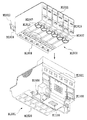
そして,記録ヘッドH1001は、図5の分解斜視図に示すように、記録素子基板H1100、第1のプレートH1200、電気配線基板H1300、第2のプレートH1400、ホルダーH1500、流路形成部材H1600、フィルターH1700、シールゴムH1800から構成されている。
【0036】
記録素子基板H1100には、Si基板の片面にインクを吐出するための複数の記録素子と、各記録素子に電力を供給するAl等の電気配線とが成膜技術により形成され、この記録素子に対応した複数のインク流路と複数の吐出口H1100Tとがフォトリソグラフィ技術により形成されると共に、複数のインク流路にインクを供給するためのインク供給口が裏面に開口するように形成されている。また、記録素子基板H1100は第1のプレートH1200に接着固定されており、ここには、前記記録素子基板H1100にインクを供給するためのインク供給口H1201が形成されている。さらに、第1のプレートH1200には、開口部を有する第2のプレートH1400が接着固定されており、この第2のプレートH1400を介して、電気配線基板H1300が記録素子基板H1100に対して電気的に接続されるよう保持されている。この電気配線基板H1300は、記録素子基板H1100にインクを吐出するための電気信号を印加するものであり、記録素子基板H1100に対応する電気配線と、この電気配線端部に位置し本体からの電気信号を受け取るための外部信号入力端子H1301とを有しており、外部信号入力端子H1301は、後述のホルダーH1500の背面側に位置決め固定されている。
【0037】
一方、インクタンクH1900を着脱可能に保持するホルダーH1500には、流路形成部材H1600が例えば、超音波溶着により固定され、インクタンクH1900から第1のプレートH1200に亘るインク流路H1501を形成している。また、インクタンクH1900と係合するインク流路H1501のインクタンク側端部には、フィルターH1700が設けられており、外部からの塵埃の侵入を防止し得るようになっている。また、インクタンクH1900との係合部にはシールゴムH1800が装着され、係合部からのインクの蒸発を防止し得るようになっている。
【0038】
さらに、前述のようにホルダーH1500、流路形成部材H1600、フィルターH1700及びシールゴムH1800から構成されるホルダー部と、前記記録素子基板H1100、第1のプレートH1200、電気配線基板H1300及び第2のプレートH1400から構成される記録素子部とを、接着等で結合することにより、記録ヘッドH1001を構成している。
【0039】
(キャリッジ)
次に、図2を参照して記録ヘッドカートリッジH1000を搭載するキャリッジM4001を説明する。
【0040】
図2に示すように、例えば、樹脂材料で成形されたキャリッジM4001には、キャリッジM4001と係合し記録ヘッドH1001をキャリッジM4001上の所定の装着位置に案内するためのキャリッジカバーM4002と、記録ヘッドH1001のホルダーH1500と係合し記録ヘッドH1001を所定の装着位置にセットさせるよう押圧するヘッドセットレバーM4007とが設けられている。
すなわち、ヘッドセットレバーM4007はキャリッジM4001の上部にヘッドセットレバー軸に対して回動可能に設けられると共に、記録ヘッドH1001との係合部には、ばね付勢されるヘッドセットプレート(不図示)が備えられ、このばね力によって記録ヘッドH1001を押圧しながらキャリッジM4001に装着する構成となっている。
【0041】
また、キャリッジM4001の記録ヘッドH1001との別の係合部にはコンタクトフレキシブルプリントケーブル(図7参照、以下、コンタクトFPCと称す)E0011が設けられ、コンタクトFPC E0011上のコンタクト部と記録ヘッドH1001に設けられたコンタクト部(外部信号入力端子)H1301とが電気的に接触し、記録のための各種情報の授受や記録ヘッドH1001への電力の供給などを行い得るようになっている。
【0042】
ここでコンタクトFPC E0011のコンタクト部とキャリッジM4001との間には不図示のゴムなどの弾性部材が設けられ、この弾性部材の弾性力とヘッドセットレバーばねによる押圧力とによってコンタクト部とキャリッジM4001との確実な接触を可能とするようになっている。さらに前記コンタクトFPC E0011はキャリッジM4001の背面に搭載されたキャリッジ基板E0013に接続されている(図7参照)。
【0043】
[スキャナ]
この実施形態におけるプリンタは、上述した記録ヘッドカートリッジH1000の代わりにキャリッジM4001にスキャナを装着することで読取装置としても使用することができる。
【0044】
このスキャナは、プリンタ側のキャリッジM4001と共に主走査方向に移動し、記録媒体に代えて給送された原稿画像をその主走査方向への移動の過程で読み取るようになっており、その主走査方向の読み取り動作と原稿の副走査方向の給送動作とを交互に行うことにより、1枚の原稿画像情報を読み取ることができる。
【0045】
図6の(a)および(b)は、このスキャナM6000の概略構成を説明するために、スキャナM6000を上下逆にして示す図である。
【0046】
図示のように、スキャナホルダM6001は、略箱型の形状であり、その内部には読み取りに必要な光学系・処理回路などが収納されている。また、このスキャナM6000をキャリッジM4001へと装着した時に、原稿面と対面する部分には読取部レンズM6006が設けられており、このレンズM6006により原稿面からの反射光を内部の読取部に収束することで原稿画像を読み取るようになっている。一方、照明部レンズM6005は内部に不図示の光源を有し、その光源から発せられた光がレンズM6005を介して原稿へと照射される。
【0047】
スキャナホルダM6001の底部に固定されたスキャナカバーM6003は、スキャナホルダM6001内部を遮光するように嵌合し、側面に設けられたルーバー状の把持部によってキャリッジM4001への着脱操作性の向上を図っている。スキャナホルダM6001の外形形状は記録ヘッドH1001と略同形状であり、キャリッジM4001へは記録ヘッドカートリッジH1000と同様の操作で着脱することができる。
【0048】
また、スキャナホルダM6001には、読取り処理回路を有する基板が収納される一方、この基板に接続されたスキャナコンタクトPCBが外部に露出するよう設けられており、キャリッジM4001へとスキャナM6000を装着した際、スキャナコンタクトPCB M6004がキャリッジM4001側のコンタクトFPC E0011に接触し、基板を、キャリッジM4001を介して本体側の制御系に電気的に接続させるようになっている。
【0049】
[プリンタの電気回路の構成]
次に、本発明の実施形態における電気的回路構成を説明する。
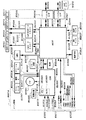
図7は、この実施形態における電気的回路の全体構成例を概略的に示す図である。
【0050】
この実施形態における電気的回路は、主にキャリッジ基板(CRPCB)E0013、メインPCB(Printed Circuit Board)E0014、電源ユニットE0015等によって構成されている。
ここで、電源ユニットE0015は、メインPCB E0014と接続され、各種駆動電源を供給するものとなっている。
また、キャリッジ基板E0013は、キャリッジM4001(図2)に搭載されたプリント基板ユニットであり、コンタクトFPC E0011を通じて記録ヘッドとの信号の授受を行うインターフェースとして機能する他、キャリッジM4001の移動に伴ってエンコーダセンサE0004から出力されるパルス信号に基づき、エンコーダスケールE0005とエンコーダセンサE0004との位置関係の変化を検出し、その出力信号をフレキシブルフラットケーブル(CRFFC)E0012を通じてメインPCB E0014へと出力する。
【0051】
さらに、メインPCBE0014はこの実施形態におけるインクジェット記録装置の各部の駆動制御を司るプリント基板ユニットであり、紙端検出センサ(PEセンサ)E0007、ASF(自動給紙装置)センサE0009、カバーセンサE0022、パラレルインターフェース(パラレルI/F)E0016、シリアルインターフェース(シリアルI/F)E0017、リジュームキーE0019、LED E0020、電源キーE0018、ブザーE0021等に対するI/Oポートを基板上に有する。またさらに、キャリッジM1400を主走査させるための駆動源をなすモータ(CRモータ)E0001、記録媒体を搬送するための駆動源をなすモータ(LFモータ)E0002、記録ヘッドの回動動作と記録媒体の給紙動作に兼用されるモータ(PGモータ)E0003と接続されてこれらの駆動を制御する他、インクエンプティセンサE0006、GAPセンサE0008、PGセンサE0010、CRFFC E0012、電源ユニットE0015との接続インターフェイスを有する。
【0052】
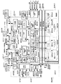
図8は、メインPCB E0014の内部構成を示すブロック図である。図において、E1001はCPUであり、このCPU E1001は内部に発振回路E1005に接続されたクロックジェネレータ(CG) E1002を有し、その出力信号E1019によりシステムクロックを発生する。また、制御バスE1014を通じてROM E1004およびASIC(Application Specific Integrated Circuit) E1006に接続され、ROMに格納されたプログラムに従って、ASIC E1006の制御、電源キーからの入力信号E1017、及びリジュームキーからの入力信号E1016、カバー検出信号E1042、ヘッド検出信号(HSENS)E1013の状態の検知を行ない、さらにブザー信号(BUZ)E1018によりブザーE0021を駆動し、内蔵されるA/DコンバータE1003に接続されるインクエンプティ検出信号(INKS)E1011及びサーミスタによる温度検出信号(TH)E1012の状態の検知を行う一方、その他各種論理演算・条件判断等を行ない、インクジェット記録装置の駆動制御を司る。
【0053】
ここで、ヘッド検出信号E1013は、記録ヘッドカートリッジH1000からフレキシブルフラットケーブルE0012、キャリッジ基板E0013及びコンタクトフレキシブルプリントケーブルE0011を介して入力されるヘッド搭載検出信号であり、インクエンプティ検出信号E1011はインクエンプティセンサE0006から出力されるアナログ信号、温度検出信号E1012はキャリッジ基板E0013上に設けられたサーミスタ(図示せず)からのアナログ信号である。
【0054】
E1008はCRモータドライバであって、モータ電源(VM)E1040を駆動源とし、ASIC E1006からのCRモータ制御信号E1036に従って、CRモータ駆動信号E1037を生成し、CRモータE0001を駆動する。E1009はLF/PGモータドライバであって、モータ電源E1040を駆動源とし、ASIC E1006からのパルスモータ制御信号(PM制御信号)E1033に従ってLFモータ駆動信号E1035を生成し、これによってLFモータを駆動すると共に、PGモータ駆動信号E1034を生成してPGモータを駆動する。
【0055】
E1010は電源制御回路であり、ASIC E1006からの電源制御信号E1024に従って発光素子を有する各センサ等への電源供給を制御する。パラレルI/F E0016は、ASIC E1006からのパラレルI/F信号E1030を、外部に接続されるパラレルI/FケーブルE1031に伝達し、またパラレルI/FケーブルE1031の信号をASIC E1006に伝達する。シリアルI/F E0017は、ASIC E1006からのシリアルI/F信号E1028を、外部に接続されるシリアルI/FケーブルE1029に伝達し、また同ケーブルE1029からの信号をASIC E1006に伝達する。
【0056】
一方、電源ユニットE0015からは、ヘッド電源(VH)E1039及びモータ電源(VM)E1040、ロジック電源(VDD)E1041が供給される。また、ASIC E1006からのヘッド電源ON信号(VHON)E1022及びモータ電源ON信号(VMOM)E1023が電源ユニットE0015に入力され、それぞれヘッド電源E1039及びモータ電源E1040のON/OFFを制御する。電源ユニットE0015から供給されたロジック電源(VDD)E1041は、必要に応じて電圧変換された上で、メインPCB E0014内外の各部へ供給される。
【0057】
またヘッド電源信号E1039は、メインPCB E0014上で平滑化された後にフレキシブルフラットケーブルE0011へと送出され、記録ヘッドカートリッジH1000の駆動に用いられる。
【0058】
E1007はリセット回路で、ロジック電源電圧E1041の低下を検出して、CPU E1001及びASIC E1006にリセット信号(RESET)E1015を供給し、初期化を行なう。
【0059】
このASIC E1006は1チップの半導体集積回路であり、制御バスE1014を通じてCPU E1001によって制御され、前述したCRモータ制御信号E1036、PM制御信号E1033、電源制御信号E1024、ヘッド電源ON信号E1022、及びモータ電源ON信号E1023等を出力し、パラレルI/F E0016およびシリアルI/F E0017との信号の授受を行なう他、PEセンサE0007からのPE検出信号(PES)E1025、ASFセンサE0009からのASF検出信号(ASFS)E1026、記録ヘッドと記録媒体とのギャップを検出するためのセンサ(GAP)センサE0008からのGAP検出信号(GAPS)E1027、PGセンサE0010からのPG検出信号(PGS)E1032の状態を検知して、その状態を表すデータを制御バスE1014を通じてCPU E1001に伝達し、入力されたデータに基づきCPU E1001はLED駆動信号E1038の駆動を制御してLEDE0020の点滅を行なう。
【0060】
さらに、エンコーダ信号(ENC)E1020の状態を検知してタイミング信号を生成し、ヘッド制御信号E1021で記録ヘッドカートリッジH1000とのインターフェイスをとり記録動作を制御する。ここにおいて、エンコーダ信号(ENC)E1020はフレキシブルフラットケーブルE0012を通じて入力されるCRエンコーダセンサE0004の出力信号である。また、ヘッド制御信号E1021は、フレキシブルフラットケーブルE0012、キャリッジ基板E0013、及びコンタクトFPC E0011を経て記録ヘッドH1000に供給される。
【0061】
図9は、ASIC E1006の内部構成例を示すブロック図である。
【0062】
なお、同図において、各ブロック間の接続については、記録データやモータ制御データ等、ヘッドや各部機構部品の制御にかかわるデータの流れのみを示しており、各ブロックに内蔵されるレジスタの読み書きに係わる制御信号やクロック、DMA制御にかかわる制御信号などは図面上の記載の煩雑化を避けるため省略している。
【0063】
図中、E2002はPLLコントローラであり、図9に示すようにCPU E1001から出力されるクロック信号(CLK)E2031及びPLL制御信号(PLLON)E2033により、ASIC E1006内の大部分へと供給するクロック(図示しない)を発生する。
【0064】
また、E2001はCPUインターフェース(CPUI/F)であり、リセット信号E1015、CPU E1001から出力されるソフトリセット信号(PDWN)E2032、クロック信号(CLK)E2031及び制御バスE1014からの制御信号により、以下に説明するような各ブロックに対するレジスタ読み書き等の制御や、一部ブロックへのクロックの供給、割り込み信号の受け付け等(いずれも図示しない)を行ない、CPU E1001に対して割り込み信号(INT)E2034を出力し、ASIC E1006内部での割り込みの発生を知らせる。
【0065】
また、E2005はDRAMであり、記録用のデータバッファとして、受信バッファE2010、ワークバッファE2011、プリントバッファE2014、展開用データバッファE2016などの各領域を有すると共に、モータ制御用としてモータ制御バッファE2023を有し、さらにスキャナ動作モード時に使用するバッファとして、上記の各記録用データバッファに代えて使用されるスキャナ取込みバッファE2024、スキャナデータバッファE2026、送出バッファE2028などの領域を有する。
【0066】
また、このDRAM E2005は、CPU E1001の動作に必要なワーク領域としても使用されている。すなわち、E2004はDRAM制御部であり、制御バスによるCPU E1001からDRAM E2005へのアクセスと、後述するDMA制御部E2003からDRAM E2005へのアクセスとを切り替えて、DRAM E2005への読み書き動作を行なう。
【0067】
DMA制御部E2003では、各ブロックからのリクエスト(図示せず)を受け付けて、アドレス信号や制御信号(図示せず)、書込み動作の場合には書込みデータE2038、E2041、E2044、E2053、E2055、E2057などをDRAM制御部E2004に出力してDRAMアクセスを行なう。また読み出しの場合には、DRAM制御部E2004からの読み出しデータE2040、E2043、E2045、E2051、E2054、E2056、E2058、E2059を、リクエスト元のブロックに受け渡す。
【0068】
また、E2006は、IEEE 1284I/Fであり、CPUI/F E2001を介したCPU E1001の制御により、パラレルI/F E0016を通じて、図示しない外部ホスト機器との双方向通信インターフェイスを行なう他、記録時にはパラレルI/F E0016からの受信データ(PIF受信データE2036)をDMA処理によって受信制御部E2008へと受け渡し、スキャナ読み取り時にはDRAM E2005内の送出バッファE2028に格納されたデータ(1284送信データ(RDPIF)E2059)をDMA処理によりパラレルI/Fに送信する。
【0069】
E2007は、ユニバーサルシリアルバス(USB)I/Fであり、CPUI/F E2001を介したCPU E1001の制御により、シリアルI/F E0017を通じて、図示しない外部ホスト機器との双方向通信インターフェイスを行なう他、印刷時にはシリアルI/F E0017からの受信データ(USB受信データE2037)をDMA処理により受信制御部E2008に受け渡し、スキャナ読み取り時にはDRAM E2005内の送出バッファE2028に格納されたデータ(USB送信データ(RDUSB)E2058)をDMA処理によりシリアルI/F E0017に送信する。受信制御部E2008は、1284I/F E2006もしくはUSBI/F E2007のうちの選択されたI/Fからの受信データ(WDIF)E2038)を、受信バッファ制御部E2039の管理する受信バッファ書込みアドレスに、書込む。
【0070】
E2009は圧縮・伸長DMAコントローラであり、CPUI/F E2001を介したCPUE1001の制御により、受信バッファE2010上に格納された受信データ(ラスタデータ)を、受信バッファ制御部E2039の管理する受信バッファ読み出しアドレスから読み出し、そのデータ(RDWK)E2040を指定されたモードに従って圧縮・伸長し、記録コード列(WDWK)E2041としてワークバッファ領域に書込む。
【0071】
E2013は記録バッファ転送DMAコントローラで、CPUI/F E2001を介したCPU E1007の制御によってワークバッファE2011上の記録コード(RDWP)E2043を読み出し、各記録コードを、記録ヘッドカートリッジH1000へのデータ転送順序に適するようなプリントバッファE2014上のアドレスに並べ替えて転送(WDWP E2044)する。また、E2012はワーククリアDMAコントローラであり、CPUI/F E2001を介したCPU E1001の制御によって記録バッファ転送DMAコントローラ E2013による転送が完了したワークバッファ上の領域に対し、指定したワークフィルデータ(WDWF)E2042を繰返し書込む。
【0072】
E2015は記録データ展開DMAコントローラであり、CPUI/F E2001を介したCPU E1001の制御により、ヘッド制御部E2018からのデータ展開タイミング信号E2050をトリガとして、プリントバッファ上に並べ替えて書込まれた記録コードと展開用データバッファE2016上に書込まれた展開用データとを読み出し、展開記録データ(RDHDG)E2045をカラムバッファ書込みデータ(WDHDG)E2047としてカラムバッファE2017に書込む。ここで、カラムバッファE2017は、記録ヘッドカートリッジH1000への転送データ(展開記録データ)を一時的に格納するSRAMであり、記録データ展開DMAコントローラE2015とヘッド制御部E2018とのハンドシェーク信号(図示せず)によって両ブロックにより共有管理されている。
【0073】
E2018はヘッド制御部で、CPUI/F E2001を介したCPU E1001の制御により、ヘッド制御信号を介して記録ヘッドカートリッジH1000またはスキャナとのインターフェイスを行なう他、エンコーダ信号処理部E2019からのヘッド駆動タイミング信号E2049に基づき、記録データ展開DMAコントローラに対してデータ展開タイミング信号E2050の出力を行なう。
【0074】
また、印刷時には、前記ヘッド駆動タイミング信号E2049に従って、カラムバッファから展開記録データ(RDHD)E2048を読み出し、そのデータをヘッド制御信号E1021として記録ヘッドカートリッジH1000に出力する。
また、スキャナ読み取りモードにおいては、ヘッド制御信号E1021として入力された取込みデータ(WDHD)E2053をDRAM E2005上のスキャナ取込みバッファE2024へとDMA転送する。E2025はスキャナデータ処理DMAコントローラであり、CPUI/F E2001を介したCPU E1001の制御により、スキャナ取込みバッファE2024に蓄えられた取込みバッファ読み出しデータ(RDAV)E2054を読み出し、平均化等の処理を行なった処理済データ(WDAV)E2055をDRAM E2005上のスキャナデータバッファE2026に書込む。
【0075】
E2027はスキャナデータ圧縮DMAコントローラで、CPUI/F E2001を介したCPU E1001の制御により、スキャナデータバッファE2026上の処理済データ(RDYC)E2056を読み出してデータ圧縮を行ない、圧縮データ(WDYC)E2057を送出バッファE2028に書込み転送する。
【0076】
E2019はエンコーダ信号処理部であり、エンコーダ信号(ENC)を受けて、CPU E1001の制御で定められたモードに従ってヘッド駆動タイミング信号E2049を出力する他、エンコーダ信号E1020から得られるキャリッジM4001の位置や速度にかかわる情報をレジスタに格納して、CPU E1001に提供する。CPU E1001はこの情報に基づき、CRモータE0001の制御における各種パラメータを決定する。また、E2020はCRモータ制御部であり、CPUI/F E2001を介したCPU E1001の制御により、CRモータ制御信号E1036を出力する。
【0077】
E2022はセンサ信号処理部で、PGセンサE0010、PEセンサE0007、ASFセンサE0009、及びGAPセンサE0008等から出力される各検出信号E1033,E1025,E1026,E1027を受けて、CPUE1001の制御で定められたモードに従ってこれらのセンサ情報をCPU E1001に伝達する他、LF/PGモータ制御用DMAコントローラ E2021に対してセンサ検出信号E2052を出力する。
【0078】
LF/PGモータ制御用DMAコントローラE2021は、CPUI/F E2001を介したCPU E1001の制御により、DRAM E2005上のモータ制御バッファE2023からパルスモータ駆動テーブル(RDPM)E2051を読み出してパルスモータ制御信号E1033を出力する他、動作モードによっては前記センサ検出信号を制御のトリガとしてパルスモータ制御信号E1033を出力する。
【0079】
また、E2030はLED制御部であり、CPUI/F E2001を介したCPU E1001の制御により、LED駆動信号E1038を出力する。さらに、E2029はポート制御部であり、CPUI/F E2001を介したCPU E1001の制御により、ヘッド電源ON信号E1022、モータ電源ON信号E1023、及び電源制御信号E1024を出力する。
【0080】
[プリンタの動作]
次に、上記のように構成された本発明の実施形態におけるインクジェット記録装置の動作を図10のフローチャートに基づき説明する。
【0081】
AC電源に装置本体1000が接続されると、まず、ステップS1では装置の第1の初期化処理を行なう。この初期化処理では、本装置のROMおよびRAMのチェックなどの電気回路系のチェックを行ない、電気的に本装置が正常に動作可能であるかを確認する。
【0082】
次にステップS2では、装置本体M1000の上ケースM1002に設けられた電源キーE0018がONされたかどうかの判断を行い、電源キーE0018が押された場合には、次のステップS3へと移行し、ここで第2の初期化処理を行う。
【0083】
この第2の初期化処理では、本装置の各種駆動機構及び記録ヘッドのチェックを行なう。すなわち、各種モータの初期化やヘッド情報の読み込みを行うに際し、装置が正常に動作可能であるかを確認する。
【0084】
次にステップS4ではイベント待ちを行なう。すなわち、本装置に対して、外部I/Fからの指令イベント、ユーザ操作によるパネルキーイベントおよび内部的な制御イベントなどを監視し、これらのイベントが発生すると当該イベントに対応した処理を実行する。
【0085】
例えば、ステップS4で外部I/Fからの印刷指令イベントを受信した場合には、ステップS5へと移行し、同ステップでユーザ操作による電源キーイベントが発生した場合にはステップS10へと移行し、同ステップでその他のイベントが発生した場合にはステップS11へと移行する。
ここで、ステップS5では、外部I/Fからの印刷指令を解析し、指定された紙種別、用紙サイズ、印刷品位、給紙方法などを判断し、その判断結果を表すデータを本装置内のRAM E2005に記憶し、ステップS6へと進む。
【0086】
次いでステップS6ではステップS5で指定された給紙方法により給紙を開始し、用紙を記録開始位置まで送り、ステップS7に進む。
ステップS7では記録動作を行なう。この記録動作では、外部I/Fから送出されてきた記録データを、一旦記録バッファに格納し、次いでCRモータE0001を駆動してキャリッジM4001の主走査方向への移動を開始すると共に、プリントバッファE2014に格納されている記録データを記録ヘッドH1001へと供給して1行の記録を行ない、1行分の記録データの記録動作が終了するとLFモータE0002を駆動し、LFローラM3001を回転させて用紙を副走査方向へと送る。この後、上記動作を繰り返し実行し、外部I/Fからの1ページ分の記録データの記録が終了すると、ステップ8へと進む。
【0087】
ステップS8では、LFモータE0002を駆動し、排紙ローラM2003を駆動し、用紙が完全に本装置から送り出されたと判断されるまで紙送りを繰返し、終了した時点で用紙は排紙トレイM1004a上に完全に排紙された状態となる。
【0088】
次にステップS9では、記録すべき全ページの記録動作が終了したか否かを判定し、記録すべきページが残存する場合には、ステップS5へと復帰し、以下、前述のステップS5〜S9までの動作を繰り返し、記録すべき全てのページの記録動作が終了した時点で記録動作は終了し、その後ステップS4へと移行し、次のイベントを待つ。
【0089】
一方、ステップS10ではプリンタ終了処理を行ない、本装置の動作を停止させる。つまり、各種モータやヘッドなどの電源を切断するために、電源を切断可能な状態に移行した後、電源を切断しステップS4に進み、次のイベントを待つ。
【0090】
また、ステップS11では、上記以外の他のイベント処理を行なう。例えば、本装置の各種パネルキーや外部I/Fからの回復指令や内部的に発生する回復イベントなどに対応した処理を行なう。なお、処理終了後にはステップS4に進み、次のイベントを待つ。
【0091】
なお、本発明が有効に用いられる一形態は、電気熱変換体が発生する熱エネルギーを利用して液体に膜沸騰を生じさせ気泡を形成する形態である。
【0092】
記録ヘッドH1001について、さらに詳細に説明する。
【0093】
記録ヘッドH1001は、電気信号に応じて膜沸騰をインクに対して生じせしめるための熱エネルギーを生成する電気熱変換体を用いて記録を行うバブルジェット方式のサイドシュータ型とされる記録ヘッドである。
【0094】
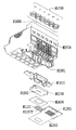
記録ヘッドH1001は、図24の分解斜視図に示すように、記録素子ユニットH1002とホルダーユニットH1003とから構成される。さらに、図25の分解斜視図に示すように、記録素子ユニットH1002は、記録素子基板H1100、第1のプレートH1200、電気配線基板H1300、および第2のプレートH1400で構成されており、また、ホルダーユニットH1003は、ホルダー(液体の供給部材)H1500、流路形成部材H1600、6個のフィルターH1700、6個のシールゴムH1800から構成されている。
【0095】
(記録素子ユニット)
図26は、記録素子基板1100の構成を説明するために一部分解した斜視図である。
【0096】
記録素子基板H1100には、上述したように、複数の記録素子と、この記録素子に対応した複数のインク流路と複数の吐出口H1100Tとがフォトリソグラフィ技術により形成されると共に、インク供給口が裏面に開口するように形成されている。また、記録素子基板H1100は、例えば、サイドシュータタイプとされ、1枚の基板で構成されている。基板において、2列で千鳥掛け状に形成される複数の吐出口H1100Tは、例えば、各インク色ごとに約1200dpi程度に形成されており、異なるインク色のインクをそれぞれ吐出するものとされる。
【0097】
記録素子基板H1100は、例えば、図26に示されるように、その表面に薄膜が形成されているSi基板1101と、基板1101上に形成されるオリフィスプレートH1112とから構成されている。
【0098】
基板1101は、例えば、厚さ0.5〜1(mm)とされ、6色のインク流路として長溝状の貫通口からなるインク供給口H1102が6列互いに平行に一体に形成されている。隣接するインク供給口H1102の相互間距離は、例えば、約2.5mmに設定されている。このように相互間距離が比較的小とされるので記録ヘッドの小型化が図られることとなる。各々のインク供給口H1102の両側には、記録素子としての電気熱変換素子H1103がそれぞれ1列ずつ千鳥状に複数個、例えば、各インク色ごとに約1200dpi程度に配列形成されている。
【0099】
基板1101上に形成される複数の電気熱変換素子H1103および各電気熱変換素子H1103に電力を供給するAl等の電気配線(図26において図示が省略される)は、成膜技術により形成されている。また、その電気配線に電力を供給するための電極部H1104は、電気熱変換素子H1103の配列方向に対して直交する方向の端部に沿って形成されている。電極部H1104は、金等のバンプH1105が複数個、上述の電気配線基板H1300の電極端子H1302にそれぞれ対応して設けられている。
【0100】
インク供給口H1102は、例えば,Si基板1101の結晶面方位を利用して、異方性エッチングを行うことにより形成される。ウエハー面に<100>、厚さ方向に<111>の結晶面方位を持つ場合、アルカリ系(KOH,TMAH,ヒトラジン等)の異方性エッチングにより、約54.7度の角度(被エッチング面の立ち上がりの内角)でエッチングが進行する。
【0101】
この方法が用いられて、所望の深さにエッチングすることにより、インク供給口H1102が形成される。
【0102】
また、基板H1101上に形成されるオリフィスプレートH1112には、図26に示されるように、各電気熱変換素子H1103に対応したインク流路を形成するためのインク流路壁H1106と吐出口1100Tとがフォトリソグラフィ技術により形成される。従って、隣接する吐出口1100Tは、互いにインク流路壁H1106により仕切られることとなる。
【0103】
各インク供給口H1102から供給される6色のインクにそれぞれ対応した6列の吐出口H1100T列が一体に1枚のオリフィスプレートH1105に形成されている。吐出口H1100T列は、電気熱変換素子H1103の配列と同様に、千鳥状に複数個、例えば、各インク色ごとに約1200dpi程度に配列形成されている。即ち、吐出口H1100Tは、電気熱変換素子H1103に対向して設けられている。
【0104】
従って、記録素子基板H1100は、6種類のインク吐出が可能なように電気熱変換素子H1103および吐出口H1100T列が同一の基板上に形成されているので従来のように各インク別に吐出口列が分割されて形成される場合に比して記録素子基板H1100の小型化が図られることとなる。
【0105】
また、オリフィスプレートH1105には、図31に示されるように、基板H1101のインク供給口H1102から供給されるインクに含まれる不所望な不純物,例えば,塵などの吐出口列H1100Tへの進入を妨害し捕集するブロックピンH1110が複数本、形成されている。ブロックピンH1110は、インク供給口H1102から供給されるインクの流れ方向に対して略直交する方向に沿ってインク流路壁H1106近傍に形成されている。また、ブロックピンH1110は、各吐出口H1100T列に平行に所定の間隔で形成されている。例えば、インク流路壁H1106とブロックピンH1110との距離CL、または、隣接するブロックピンH1110の相互間距離CLが、10(μm)程度とされる。
【0106】
従って、ブロックピンH1110により、インクに含まれる塵などが捕集されるので記録ヘッドを組立する際等に記録ヘッド内に混入した塵等が吐出口H1107列に詰まり、その結果、印字不良(不吐、ヨレ)を引き起こすことが、防止される。
【0107】
従って、本実施例においては、ホルダーH1500に外部からのゴミ進入防止に優れたフィルターH1700を配置するとともに、記録素子基板H1100に吐出口の目詰まりを防止するためのフィルター構造がオリフィスプレートH1105内に形成されるので安価で信頼性の高い記録ヘッドが提供できることとなる。
【0108】
図32の(A)および図32の(B)に示される第1のプレートH1200は、例えば、厚さ0.5〜10mmのアルミナ(Al2O3)材料で形成されている。なお、第1のプレートの素材は、アルミナに限られることなく、好ましくは、セラミックスのような記録素子基板H1100の材料の線膨張率と同等の線膨張率を有し、かつ、記録素子基板H1100材料の熱伝導率と同等もくしは同等以上の熱伝導率を有する材料で作られてもよい。第1のプレートH1200の素材は、例えば、シリコン(Si)、窒化アルミニウム(AlN)、ジルコニア、窒化珪素(Si3N4)、炭化珪素(SiC)、モリブデン(Mo)、タングステン(W)のうちいずれであってもよい。第1のプレートH1200には、記録素子基板H1100に6色のインクを供給するための6つのインク供給口H1201が形成されている。記録素子基板H1100の6つのインク供給口H1102が第1のプレートH1200の6つのインク供給口H1201にそれぞれ対応して位置決めされ、かつ、記録素子基板H1100は第1のプレートH1200に対して位置精度良く接着固定される。接着に用いられる第1の接着剤H1202は、第1のプレートH1200上に略記録素子基板形状で、しかも、隣り合うインク供給口間にエアーパスが発生しないように塗布される。その第1の接着剤H1202は、例えば、粘度が比較的低く、接触面に形成される接着層が薄く、かつ、硬化後、比較的高い硬度を有し、かつ、耐インク性のあるものが望ましい。その第1の接着剤H1202は、例えば、エポキシ樹脂を主成分とした熱硬化接着剤であり、接着層の厚みは50μm以下が望ましい。
【0109】
第1のプレートH1200は、図32の(A)および図32の(B)に示されるように、突起部H1200Aを両端部にそれぞれ有している。突起部H1200Aは、上述の基準端面部H1502aおよびH1502bにそれぞれ係合される基準面としての係合面H1200a(以下、基準面1200aともいう)を有している。突起部H1200Aは、その側面部に対して略垂直に、即ち、ホルダーH1500の移動方向に沿って突出している。また、ホルダーH1500の位置決めピンIPに対応した位置に、位置決めピンIPの先端が係合される透孔H1200dが形成されている。
【0110】
各インク供給口H1201は、図33の(B)に示されるように,記録素子基板H1100が接着される端面H1200sに向けて開口するインク流路としての拡大部H1202にそれぞれ連通している。細長い溝とされる拡大部H1202は、相対向して形成される斜面部H1202aおよび斜面部H1202bにより囲まれて形成されており、その断面積が記録素子基板H1100が接着される端面に向かうにつれて拡大するものとされる。
【0111】
このような形状の拡大部H1202とする理由としては、例えば、図33の(C)に示されるように,第1のプレートH1200”のインク供給通路H1201”の形状が円柱管形状である場合、インクタンク交換時や、その他の印字不良が発生した際、不図示の回復手段によって記録素子基板H1100側からインクの吸引回復を行なったとき、記録素子基板H1100の両端部においてインクの流れのよどみ部が発生するので泡AIが、たまりやすい。従って、十分な回復が行なわれ無いことに起因して、印字不良が引き起こされる虞がある。
【0112】
そこで、第1のプレート1200のインク流路の形状を記録素子基板H1100に設けられたインク供給口に向かって広がるテーパー形状としたので記録素子基板H1100の両端部のインク流れがスムーズになり泡だまりが解消される。
【0113】
従って、記録ヘッドの大型化およびコストアップをまねくことなく、容易に信頼性の高い記録ヘッドを供給することができることとなる。
【0114】
電気配線基板H1300は、図25および図26に示されるように、記録素子基板H1100に対してインクを吐出するための電気信号を印加するものであり、記録素子基板H1100を組み込むための開口部H1300aと、記録素子基板H1100の電極部H1104に対応する電極端子H1302と、この配線端部に位置し本体装置からの電気信号を受け取るための外部信号入力端子H1301を有している。
【0115】
電気配線基板H1300の開口部H1300aは、第1のプレートH1200上に配される記録素子基板H1100および第2のプレートH1400の開口部H1400aに対応している。
電気配線基板H1300と記録素子基板H1100とは、電気的に接続されている。その接続方法は、例えば、記録素子基板H1100の電極部H1104と電気配線基板H1300の電極端子H1302との間に熱硬化接着樹脂H1304(不図示)を塗布後、前記記録素子基板H1100の電極部H1104と前記電気配線基板H1300の電極端子H1302とをヒートツールにて一括で加熱加圧されて、熱硬化接着樹脂H1304を硬化させることにより、該電極部H1104と該電極端子H1302とは電気的に一括接続される。また、熱硬化接着樹脂H1304としては、導電粒子を含んだ異方性導電接着剤を用いた場合も、同様に可能である。本実施例の構成において、例えば、ニッケルの単粒子径が2〜6μmの導電粒子とエポキシ樹脂を主成分とする接着剤で構成される異方性導電接着膜を用いて、記録素子基板H1100の電極部H1104と電気配線基板H1300の金メッキされた電極端子H1302を、温度170〜250℃で加熱圧着したところ、好適に電気接続された。電気配線基板H1300の素材としては、例えば、配線が二層構造のフレキシブル配線基板が使用され、表層はレジストフィルムで覆われている。また、外部信号入力端子H1301の裏面側には、補強板H1303が接着され、外部信号入力端子H1301部の平面性を向上させている。補強板H1303の素材としては、例えば0.5〜2mmのガラスエポキシ樹脂、アルミ等の耐熱性のある材料が使用される。
【0116】
第2のプレートH1400は、例えば、厚さ0.5〜1mmのアルミナ(Al2O3)材料で形成されている。なお、第2のプレートの素材は、アルミナに限られることなく、記録素子基板H1100及び第1のプレートH1200と同等の線膨張率を有し、かつ、それらの熱伝導率と同等もしくは同等以上の熱伝導率を有する材料で作られてもよい。そして、第2のプレートH1400は、図25に示されるように、第1のプレートH1200に接着固定された記録素子基板H1100の外形寸法よりも大きな開口部を有する形状となっている。また、記録素子基板H1100と電気配線基板H1300とを平面的に電気接続できるように,第2のプレートH1400が第1のプレートH1200に第2の接着剤H1203により接着されている。一方、電気配線基板H1300の裏面も、第3の接着剤H1306により第2のプレートH1400に接着固定される。また、電気配線基板H1300は、第2のプレートH1400に接着されると同時に、第1のプレートH1200及び第2のプレートH1400の一側面で折り曲げられ、第1のプレートH1200の側面に第3の接着剤H1306で接着される。第2の接着剤H1203は、例えば、粘度が低く、接触面に形成される接着層が薄く、かつ、耐インク性のあるものが使用される。また、第3の接着剤H1306は、例えば、エポキシ樹脂を主成分とした厚さ10〜100μmの熱硬化接着膜が使用される。
【0117】
以上のように構成された記録素子ユニットH1002の記録素子基板H1100と電気配線基板H1300との電気接続部分は、図24に示されるように、第1の封止剤(不図示)及び第2の封止剤H1308により封止され、電気接続部分をインクによる腐食や外的衝撃から保護している。第1の封止剤は、主に記録素子基板H1100の外周部分を封止し、第2の封止剤は、電気配線基板H1300の開口部のエッジを封止している。また、折り曲げられた電気配線基板H1300は、ホルダーH1500の背面形状に合わせて、さらに、フォーミングされる。
【0118】
(ホルダーユニット)
ホルダーH1500は、例えば、樹脂成形により形成される。該樹脂材料には、形状的剛性を向上させるためにガラスフィラーを5〜40%混入した樹脂材料を使用することが望ましい。ホルダーH1500は、着脱自在のインクタンクH1900を保持するものであり、図27に示すインクタンクH1900のタンク位置決めピンH1908、第1の爪H1909、第2の爪H1910、第3の爪H1911をそれぞれ係合するタンク位置決め穴1520、第1の穴(不図示)、第2の穴(不図示)、第3の穴1521、及び、インク残量検知に使用するプリズムH1913のための開口部H1506を図25に示されるように有している。また、ホルダーH1500は、記録ヘッドカートリッジH1000をインクジェット記録装置本体のキャリッジM4001に装着位置に案内するための装着ガイドH1507、記録ヘッドカートリッジをヘッドセットレバーによりキャリッジに装着固定するための係合部H1508(図27)、及びキャリッジの所定の装着位置に位置決めするためのX突き当て部H1509、Y突き当て部H1510、およびZ突き当て部H1511を備えている。ホルダーH1500は、記録素子ユニットH1002の外部信号入力端子H1301部分を位置決め固定する端子固定部H1512を有している。端子固定部H1512及びその周囲には複数のリブが設けられているので、端子固定部H1512を有する面の剛性が高められている。また、各インクタンクH1900が装着される各セル相互間には、各色の混色を防止するリブH1516(図30)が設けられている。また、ホルダーH1500の側面には、手掛かり部H1513(図25)が設けられることにより、記録ヘッドH1001のハンドリング性が向上されている。
【0119】
また、図28に示すように、ホルダーH1500は、インクタンクH1900から記録素子ユニットH1002にインクを導くためのインク流路H1501を形成するホルダーユニットH1003の一構成部品である。流路形成部材H1600がホルダーH1500に超音波溶着されることにより、インク流路H1501が形成されている。また、インクタンクH1900と係合するジョイントH1517には、外部からのゴミの進入を防ぐためのフィルターH1700が熱溶着により接合されており、さらに、ジョイント部H1517からのインクの蒸発を防止するために、シールゴムH1800が装着されている。フィルターH1700は、例えば、空孔径10μm以下のSUS繊維を焼結したフィルターとされ、ドーム状にフォーミングし熱溶着でジョイント部H1518に固定されている。その際、そのドーム状の凸量としては、0.1〜0.5(mm)程度となる最大の曲率半径の形状が好ましい。
【0120】
このようなフィルターH1700を設けることにより、外部からの塵の進入に対して効果的であるばかりでなく、各ジョイント部H1517とインクタンクH1900との接続も良好となる。
【0121】
ホルダーH1500の正面部には、図29に示されるように、複数のスリットSLがインク収容部に対応して形成されている。また、その下方となるホルダーH1500の下端部の略中央には、凹凸面を形成する複数の縦溝H1530が2箇所に形成されている。
【0122】
各凹凸面における縦溝H1530は、溝巾1mm、深さ0.2mm、溝本数14本、溝間隔2mmに設定されている。なお、縦溝H1530は、図28に示されるように,ワイピング作業の際、その下端面に溜まったインクIKを十分保持できる毛管力が発生するように、溝巾、および、深さと、溝本数とを有していれば良く、形状は任意に設定してもよい。
【0123】
従って、例えば、図28に示されるように、インク吐出口形成面を清浄化するクリーニング用のブレードBLが、配線基板H1300の折り曲げ部側(背面側)から進入され正面部側に移動せしめられることによってワイピング作業が繰り返し行なわれる場合、ブレードBLによりインクがその下端面に集められることにより、インクIKがこの端面に溜まる場合がある。この場合、そのインクIKが落下することにより、その下方の記録紙を汚す虞がある。
【0124】
しかし、縦溝H1530がその端面に設けられることにより、そのインクIK溜まりがその毛管力により保持され、例えば、記録紙上への落下することが防止でき、記録紙の汚染、記録品位の低下が防止される。
【0125】
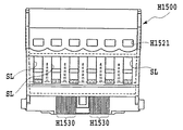
ホルダーH1500において、流路形成部材H1600が挿入され固定される部分には、図11に示されるように、一端が上述のインク供給孔H1520に連通し、他端が流路形成部材H1600のインク流路の開口端に対応して形成される溝状のインク流路H1521がそれぞれ、各インクタンクH1900に対応して形成されている。従って、各インク流路H1521の他端の相互間隔が、一端の相互間隔に比して小となるように、各インク流路H1521の他端は、流路形成部材H1600のインク流路の開口端に対応して集合している。ホルダーH1500における固定される部分に流路形成部材H1600の当接面が接合されることにより、各インクタンクH1900からの各インクをそれぞれ流路形成部材H1600の各インク流路に供給するインク供給路が形成されることとなる。
【0126】
また、流路形成部材H1600が挿入され固定される部分には、流路形成部材H1600および第1のプレートH1200に係合される位置決め用のピンIPが植立されている。
【0127】
(記録ヘッドユニットとホルダーユニットとの結合)
先述の図24に示した通り、記録ヘッドH1001は、記録素子ユニットH1002をホルダーユニットH1003に結合されることにより完成する。結合は以下のように行われる。
【0128】
記録素子ユニットH1002のインク供給口(第1のプレートH1200のインク供給口H1201)とホルダーユニットH1003のインク供給口(流路形成部材H1600のインク供給口H1601)を連通させるように第4の接着剤H1602を塗布し、第1のプレートH1200と流路形成部材H1600とを接着固定する。また、インク供給口部分以外にも、記録素子ユニットH1002におけるホルダーユニットH1003の接する部分も数ケ所、第5の接着剤H1603で接着固定されている。第4の接着剤H1602と第5の接着剤H1603とは、耐インク性があり、かつ、常温で硬化し、かつ、異種材料間の線膨張差に耐えられる柔軟性のある接着剤が望ましく、本実施例においては、例えば、吸湿硬化型のシリコーン接着剤を使用している。また、第4の接着樹脂H1602と第5の接着樹脂H1603とは、同一の接着剤でも構わない。また、記録素子ユニットH1002をホルダーユニットH1003に第4の接着剤H1602および第5の接着剤H1603で接着する際に、記録素子ユニットH1002は、流路形成部材H1600に塗布される第6の接着剤H1604で位置決め固定される。該第6の接着剤H1604は、瞬時に硬化する接着剤が望ましく、本実施例においては、例えば、紫外線硬化接着剤を使用しているが、他の接着剤でも構わない。
【0129】
記録素子ユニットH1002の外部信号入力端子H1301部分は、ホルダーH1500の一側面に、端子位置決めピンH1515(2ケ所)と端子位置決め穴H1309(2ケ所)とにより位置決めされ、固定される。固定方法は、例えば、ホルダーH1500に設けられた端子結合ピンH1516(6箇所)と、電気配線基板H1300の外部信号入力端子H1301周辺に設けられた端子結合穴H1310(6箇所)とをはめ合わされ、端子結合ピンH1515を熱溶着することにより固定しているが、その他の固定手段を用いても良い。
【0130】
(記録ヘッドカートリッジの説明)
先述の図27は、記録ヘッドカートリッジH1000を構成する記録ヘッドH1001とインクタンクH1900との装着を説明する図であり、各インクタンクH1900の内部には、記録ヘッドH1001のインク供給口H1201にそれぞれ対応する互いに異なる色のインクまたは濃度の異なるインクが収納されている。また、それぞれのインクタンクには、インクタンク内のインクを記録ヘッドH1001に供給するためのインク供給口H1907が形成されている。インクタンクH1901が記録ヘッドH1001に装着された状態で、例えば、インクタンクH1900内のブラックのインクがインク供給口H1907を介して記録ヘッドH1001に供給される。
【0131】
図27の矢印に示す方向に沿って挿入されて,記録ヘッドH1001のホルダーH1500に装着される各インクタンクH1900は、それぞれ、独立して着脱可能とされる。各インクタンクH1900は、例えば、ブラック、ライトシアン、ライトマゼンタ、シアン、マゼンタ、イエローのインクを貯留するものとされる。
【0132】
また、各インクタンクH1900には、着脱のとき操作される可動レバーH1912、および可動レバーH1912と一体に形成されホルダーH1500に選択的に係合される爪部H1909が一方の端面部に設けられている。また、その一方の端面部に対向する端面部には、装着時、ホルダーH1500の透孔H1521およびH1508に係合される爪部H1911およびH1910がそれぞれ形成されている。
【0133】
さらに、各インクタンクH1900の底部には、ホルダーH1500の各ジョイント部H1517に接続されるインク供給口H1907が設けられている。これにより、各インクがジョイント部H1517を介して流路形成部材H1600の各連通路H1600dにそれぞれ供給されることとなる。
【0134】
また、その底部には、インクタンクH1900内のインク残量を検出するための検出器からの光ビームが照射されるプリズムH1913が設けられている。さらに、位置決めピンH1908がプリズムH1913に隣接して形成されている。
【0135】
また、先述の図28は、記録ヘッドカートリッジH1000の断面図である。図28に示すように、箱状の記録ヘッドH1001の下面の一側部側に記録素子基板H1100が設けられている。また、記録ヘッドH1001には、先述のようにジョイント部H1517が設けられており、ジョイント部H1517には、記録素子基板H1100に向かって延びるインク流路H1501が内部に形成されている。このような記録ヘッドカートリッジにおけるインクの流れとして、ブラックのインク用のインクタンクH1900を例にとって説明する。インクタンクH1900内のインクはインクタンクH1900のインク供給口H1907及びジョイントH1517を介して記録ヘッドH1001内に供給される。記録ヘッドH1001内に供給されたインクは、インク流路H1501を通して第1のプレートH1200に供給され、さらに、第1のプレートH1200から記録素子基板H1100のインク供給口H1102(図26)に供給される。そして、電気熱変換素子H1103と吐出口H1100Tのある発泡室に供給される。その発泡室に供給されたインクは、電気熱変換素子H1103に与えられる熱エネルギーによって各吐出口H1100Tを通じて被記録媒体である記録用紙に向けて吐出される。
【0136】
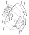
さらに、図16は、本発明に係る液体吐出記録ヘッドを備える記録装置の実施例におけるキャリッジM4001およびその周囲を拡大して示す斜視図である。
【0137】
キャリッジM4001は、シャーシM3019の両側面の間に架設されたキャリッジ軸M4012とキャリッジレール(不図示)とに案内されて矢印Sの示す方向に往復走査されるように構成され、キャリッジM4001におけるキャリッジ軸M4012の軸受け部には、焼結製の金属等にオイル等の潤滑剤を含浸させてなる一対のキャリッジ軸受けがインサート成形等の方法により一体的に形成されている。さらにキャリッジM4001のキャリッジレールとの当接部には、摺動性や耐摩耗性に優れた樹脂等によって当接部材であるキャリッジスライダ(CRスライダ)M4014が設けられ、前述の軸受け部とによりキャリッジM4001の円滑な走査を可能とするように構成されている。
【0138】
また、キャリッジM4001は、アイドラプーリとキャリッジモータプーリとの間にキャリッジ軸M4012と略平行に張架されたキャリッジベルトM4018に固定されている。キャリッジモータの駆動によってキャリッジモータプーリが回動せしめられ、キャリッジベルトM4018を往動方向または復動方向へと移動させることにより、キャリッジM4001がキャリッジ軸M4012に沿って走査させ得るようになっている。また、キャリッジモータプーリは、シャーシによって定位置に保持されているが、アイドラプーリは、プーリホルダM4021(図2参照)と共にシャーシM3019に対して移動可能に保持され、キャリッジモータプーリから離間する方向へとばねによって付勢されているため、キャリッジベルトM4018には、常に適度な張力が付与され、弛みのない良好な架設状態が維持されるようになっている。
なお、キャリッジベルトM4018とキャリッジM4001との取付部分には、キャリッジベルト止めが設けられており、これによって、キャリッジベルトM4018とキャリッジM4001との取り付けを確実に行い得るようになっている。
【0139】
キャリッジM4001には、キャリッジM4001と係合し記録ヘッドH1001をキャリッジM4001の装着位置に案内するためのキャリッジカバーM4002と、記録ヘッドH1001のホルダーH1500と係合し記録ヘッドH1001を所定の装着位置にセットさせるよう押圧するヘッドセットレバーM4007とが設けられている。
すなわち、ヘッドセットレバーM4007は、キャリッジM4001の上部にヘッドセットレバー軸(図16において図示されていない)に対して回動可能に設けられると共に、ヘッドセットレバーM4007における記録ヘッドH1001との係合部には、不図示のヘッドセットプレートがばねを介して備えられ、このばね力によって記録ヘッド1001を押圧しながらキャリッジM4001に装着する構成となっている。
【0140】
また、キャリッジM4001の記録ヘッドH1001との別の係合部にはコンタクトフレキシブルプリントケーブル(以下、コンタクトFPCと称す)E0011が設けられ、コンタクトFPC E0011上のコンタクト部E0011aと記録ヘッドH1001に設けられたコンタクト部(外部信号入力端子)H1301とが電気的に接触し、記録のための各種情報の授受や記録ヘッドH1001への電力の供給などを行い得るようになっている。
【0141】
ここで、コンタクトFPC E0011のコンタクト部とキャリッジM4001との間には不図示のゴムなどの弾性部材が設けられている。この弾性部材の弾性力とヘッドセットレバーのばねによる押圧力とによって、そのコンタクト部とキャリッジM4001との確実な接触を可能とするようになっている。さらに、前記コンタクトFPC E0011は、キャリッジM4001の両側面部に引き出され、一対のFPC押さえM4003によって両端部がキャリッジM4001の両側面部に挟持、固定されている。コンタクトFPC E0011は、キャリッジM4001の背面に搭載されたキャリッジ基板に接続されている(図16において図示されていない)。
【0142】
また、キャリッジM4001の底部においては、その両側部を連結する連結部材M4002Bにより二つに分割されることにより、キャリッジM4001内部とその下方とを連通させる開口部M4002A、および、開口部M4002Bが形成されている。
【0143】
開口部M4002Aの周縁には、図12に示されるように、係合部M4002aが相対向して形成されている。係合部M4002aは、装着されるホルダーH1500の基準端面部H1502aおよびH1502bがそれぞれ着脱可能に係合される基準面としての一対の係合面を有する。
【0144】
装着される記録ヘッドH1001の一部を構成するホルダーH1500は、図11および14にも示されるように、外部信号入力端子H1301が位置決め固定される背面側の下端部に、基準端面部H1502aおよびH1502bを有している。基準端面部H1502aおよびH1502bは、それぞれ、流路形成部材H1600が挿入され固定される部分の周縁を形成する壁部における同一平面上に形成されている。従って、基準端面部H1502aおよびH1502bは、同一平面上に形成されているので成形加工時、同時に成形することが容易となる。
【0145】
また、基準端面部H1502aおよびH1502bは、それぞれ、流路形成部材H1600が挿入され固定される部分の周縁に形成される切欠き部H1503aおよびH1503bを通じて側方に連通している。さらに、基準端面部H1502aおよびH1502bが形成される壁部の中央には、第1のプレートH1200の端部が係合される切欠部H1504が形成されている。
【0146】
流路形成部材H1600は、図11および図14に示されるように、組み合わされる第1のプレートH1200に対向する面側に、第1のプレートH1200の両端部を挟持する突起片H1600aおよびH1600bを有している。
【0147】
その際、ホルダーH1500に固定された突起片H1600aおよびH1600bとホルダーH1500の基準端面部H1502aおよびH1502bとの間には、第1のプレートH1200の突起部H1200Aがそれぞれ係合される所定の隙間が形成されることなる。
【0148】
また、相対向する突起片H1600aと突起片H1600bとの間には、図34の(A)および(B)に示されるように、第1のプレートH1200の各インク供給口H1201、および、上述の各インク流路H1521の他端にそれぞれ対応して連通孔H1600dが所定の相互間隔で互いに平行に一直線上に形成されている。各連通孔H1600dの開口端部において、第1のプレートH1200が接着される側の周縁には、円形状の縁H1600eがそれぞれ他の部分に対して隆起して形成されている。各縁H1600eは、第1のプレートH1200と接合されるとき、第1のプレートH1200の各インク供給口H1201に係合するものとされる。即ち、各連通孔H1600dは、第1のプレートH1200内に連通されることとなる。
【0149】
このような構成において、上述の記録ヘッドH1001を組み立てるにあたっては、先ず、吐出口H1100Tが形成された記録素子基板H1100は、第1のプレートH1200のインク供給口H1201に対応してその表面上に位置決めされて配される。位置決めするにあたっては、記録素子基板H1100の吐出口H1100Tの配列方向が突起部H1200Aの係合面H1200aに対して所定の角度をなすように位置決めされる。その際、記録素子基板H1100は、例えば、熱硬化型接着剤が第1のプレートH1200との間に塗布されて接着される。このように熱硬化型接着剤が利用された場合であっても、記録素子基板H1100の線膨張係数と第1のプレートH1200の線膨張係数とは、比較的近似した値とされるので熱変形による位置決め精度が低下することが回避される。その結果、記録素子基板H1100の第1のプレートH1200に対する位置決め精度、および、記録素子基板H1100のホルダーH1500の移動方向に対する位置決め精度は、向上することとなる。
【0150】
上述の記録素子基板H1100の第1プレートH1200に対する位置決め方法は、例えば、図13の(B)、および図13の(C)に示されるように、各アライメントマークAy1,Ay2,Am1、Am2、Ac1,およびAc2と、基準面H1200aおよび後述する基準面1200bとが利用される。
【0151】
上述したように、第1のプレートH1200には、その長手方向の両側の突起部H1200Aに2つの矢印Y方向(キャリッジM4002の走査方向に略直交する方向)の基準面H1200aが設けられている。このY方向の基準面H1200a(図13の(B)において紙面に対し垂直な面)は、複数の記録素子基板H1100y、H1100m、H1100cの配列方向と交差する方向に関して第1のプレートH1200をホルダーH1500に位置決めするときの基準である。
【0152】
また、第1のプレートH1200の一方の端面における突起部H1200A近傍には、基準面H1200aに直交するような矢印Xの示す方向の基準面H1200b(図13の(B)において紙面に対し垂直な面)が形成されている。
【0153】
例えば、この2つのY方向の基準面H1200aを互いに結んだ線をY基準線YLと呼び、一方、第1のプレートH1200に設けられたX方向の基準面H1200bを通り、Y基準線YLに対して鉛直に延びる線をX基準線XLと呼ぶものとする。
【0154】
さらに、記録素子基板H1100y、H1100m、H1100cには、それぞれ、その長手方向の両端に近い所定位置にアライメントマークAy1,Ay2,Am1、Am2、Ac1,および、Ac2が設けられている。一対のアライメントマークAy1,Ay2は、共通直線上に設けられている。なお、一対のアライメントマークAm1、Am2、Ac1,および、Ac2も同様に共通直線上に設けられている。
【0155】
アライメントマークAy1は、互いに、各基板のアライメントマークAm1、およびAc1に対応した所定位置に設定され、アライメントマークAy2は、各基板のアライメントマークAm2、およびAc2に対応した所定位置に設定されている。
【0156】
記録素子基板H1100y、H1100m、H1100cの位置決めにあたっては、先ず、そのアライメントマークが設けられている側において最もY方向の基準面H1200aに近いとされる記録素子基板H1100yから位置決めが,画像処理が用いられて行われる。その際、各記録素子基板H1100y、H1100m、H1100cは、図示されない把持手段により保持され、後述する被接着面に対し近接した状態で位置決めされる。
【0157】
記録素子基板H1100yのアライメントマークAy1が、y方向の基準面H1200aに対して所定値Yy1の距離だけ離隔するように位置決めされるとともに、X方向の基準面H1200bからも所定値Xy1離隔するように位置決めされる。
【0158】
次に、アライメントマークAy2がX方向の基準面H1200bに対し所定値Xy2の距離だけ離隔するように位置決めされる。記録素子基板1100yの端面の傾きがY基準線YLに対して90°と成る場合、所定値Xy1と所定値Xy2とは等しくなる。
【0159】
続いて、記録素子基板H1100mの位置決めが行われる。記録素子基板H1100mのアライメントマークAm1、Am2が、X方向に関し記録素子基板H1100yのアライメントマークAy1,Ay2に対し任意の値である所定値X(m1-y1),X(m2-y2)の距離だけ離隔するように夫々、位置決めされる。一方、アライメントマークAm1のY方向の位置に関しては、Y基準線YLからの距離Ym1が所定値Yy1に等しくなるように位置決めされる。
【0160】
同様にして、記録素子基板H1100cは、そのアライメントマークAc1、Ac2が記録素子基板H1100yのアライメントマークAy1,Ay2に対し任意の値である所定値X(c1-y1),X(c2-y2)の距離、離隔するように夫々位置決めされる。一方、アライメントマークAc1のY方向の位置に関しては、Y基準線YLからの距離Yc1 が所定値Yy1に等しくなるように位置決めされる。
【0161】
このようにして記録素子基板H1100y、H1100m、H1100cの位置決めが行われた後、上述したように、記録素子基板H1100y、H1100m、H1100cが第1のプレートH1200に熱硬化型接着剤H1204を用いて接着される。本実施形態においては、熱硬化型接着剤として、紫外線による硬化も併用できる接着剤が用いられている。即ち、先ず、接着剤に対する紫外線の照射により記録素子基板H1100y、H1100m、H1100cが仮固定された後、その接着剤が加熱されることにより、接着剤が完全に硬化し、その結果、記録素子基板H1100y、H1100m、H1100cが確実に固定される。
【0162】
また、第1のプレートH1200の基準面H1200aの接触面積は、比較的小とされるので基準面H1200aを加工する場合、加工精度を高めることが容易となる。
【0163】
続いて、第2のプレートH1400、および、電気配線基板H1300が、図15に示されるように,第1のプレートH1200上に重ねられて載置され、電気配線基板H1300は電気的に記録素子基板H1100の電極に接続される。
【0164】
次に、常温または比較的低温度で硬化するシリコン系接着剤Boが、図14に示されるように、ホルダーユニットH1003(流路形成部材H1600)の透孔H1600dの周囲に塗布された後、図15に示されるように、記録素子ユニットH1002の記録素子基板H1100および電気配線基板H1300が固定された第1のプレートH1200が、突起片H1600aおよびH1600bに挟持され、切欠部H1504に係合され流路形成部材H1600における透孔H1600dが形成される面に接着される。その際、第1のプレートH1200は、その突起部H1200Aが突起片H1600aおよびH1600bとその基準端面部H1502aおよびH1502bとの間に係合されるとともに、その係合面H1200aがその基準端面部H1502aおよびH1502bに当接され、第6の接着剤H1604(図24参照)により接着固定される。従って、記録素子ユニットH1002の第1のプレートH1200は、その接着のとき、加熱されることなく、また、その記録素子基板H1100の吐出口H1100T列のホルダーH1500の基準端面部H1502aおよびH1502bに対しての所定の位置決め精度が保たれて固定されることとなる。
【0165】
続いて、記録素子ユニットH1002が固定されたホルダーH1500は、インクタンクH1900とともに、図12および図13Aに示されるように、矢印の示す方向に沿ってキャリッジM4002内に挿入されて装着される。その際、ホルダーH1500の基準端面部H1502aおよびH1502bは、それぞれ、係合部M4002aの係合面に当接されることとなる。従って、装着されたホルダーH1500における記録素子基板H1100の吐出口H1100T列は、キャリッジM4002の移動方向に対し所定の角度をなしてキャリッジM4002に精度よく位置決めされることとなる。
【0166】
図17および図18は、本発明に係る液体吐出記録ヘッドの第2の実施例の要部を示す。
【0167】
図17においては,図14に示される例における流路形成部材H1600の突起片H1600aおよび突起片H1600bにさらに加えて流路形成部材H1600が挿入され固定される部分の周縁に、押圧片H1505が一体に形成されている。押圧片H1505は、第1のプレートH1200の係合面H1200aをホルダーH1500の基準端面部H1502aおよびH1502bに対してその弾性力で押圧するものとされる。
【0168】
なお、図17および図18においては、図13A、図14および図15に示される例における構成要素と同一とされる構成要素について同一の符号を付して示し、その重複説明を省略する。
【0169】
押圧片H1505の一端は、流路形成部材H1600が挿入され固定される部分の周縁における突起片H1600aと突起片H1600bとの間の中間部分に連結されており、また、押圧片H1505の他端は、作用される外力に応じて変位可能な自由端とされる。
【0170】
このような構成において,上述の記録ヘッドH1001を組み立てるにあたっては、先ず、吐出口H1100Tが形成された記録素子基板H1100は、上述の第1の実施例と同様に、第1のプレートH1200のインク供給口H1201に対応してその表面上に係合面H1200aに対して位置決めされて配される。その際、記録素子基板H1100は、例えば,熱硬化型接着剤が第1のプレートH1200との間に塗布されて接着される。次に、第2のプレートH1400および電気配線基板H1300が、第1のプレートH1200上に重ねて載置され、その電気配線基板H1300は、電気的に記録素子基板H1100の電極に接続されることにより、図24に示されるような、記録素子ユニットH1002として構成される。
【0171】
続いて、常温または比較的低温度で硬化するシリコン系接着剤Boが、図17および図24に示されるように、ホルダーユニットH1003(流路形成部材H1600)の透孔H1600dの周囲に塗布された後、記録素子ユニットH1002の第1のプレートH1200が、押圧片H1505の弾性力に抗して突起片H1600aおよびH1600bに挟持され、かつ、切欠部H1504に係合され、透孔H1600dが形成される面に接着される。その際、第1のプレートH1200は、その突起部H1200Aが突起片H1600aおよびH1600bとその基準端面部H1502aおよびH1502bとの間に係合されるとともに、その係合面H1200aがその基準端面部H1502aおよびH1502bに当接される。また、加えて、押圧片H1505の弾性力により、第1のプレートH1200の係合面H1200aがその基準端面部H1502aおよびH1502bに対して押圧されることとなる。
【0172】
従って、第1のプレートH1200は、接着のとき、加熱されることなく、また、その記録素子基板H1100の吐出口H1100T列のホルダーH1500の基準端面部H1502aおよびH1502bに対しての所定の位置決め精度が保たれて固定されることとなる。さらに、常温硬化型である接着材Boの硬化待ち時間(8〜12時間)の間、及び硬化後も常に突き当て方向に荷重を第1のプレートH1200にかけることができるので確実に吐出口列の傾き精度を出すことができる。ヒートサイクル試験においても、端面部H1502aおよびH1502bに対する係合面H1200aの突き当て精度が良好となることが本発明者による試験により確認されている。
【0173】
続いて、記録素子ユニットH1002の外部信号入力端子H1301部分は、図24および27に示されるように、ホルダーH1500の一側面に位置決め固定される。
【0174】
続いて、記録ヘッドH1001は、インクタンクH1900とともに、図18に示されるように、キャリッジM4002内に挿入されて装着される。その際、ホルダーH1500の基準端面部H1502aおよびH1502bは、それぞれ、係合部M4002aの係合面に当接されることとなる。従って、装着されたホルダーH1500における記録素子基板H1100の吐出口H1100T列は、キャリッジM4002の移動方向に対し所定の角度をなしてキャリッジM4002に自動的に精度よく位置決めされることとなる。
【0175】
図19は、本発明に係る液体吐出記録ヘッドの第3の実施例の要部を、キャリッジM4002とともに示す。図19は、記録素子基板H1100および電気配線基板H1300などが組みつけられたホルダー1500がキャリッジM4002内に装着された状態を示す。
【0176】
図19に示される例においては、図17に示される例では押圧片H1505の弾性力により、第1のプレートH1200の係合面H1200aがその基準端面部H1502aおよびH1502bに対して押圧されるが、その代わりに、皿ビスBsの締結力におけるその半径方向の分力により第1のプレートH1200’の係合面H1200a’がその基準端面部H1502aおよびH1502bに対して押圧されるものとされる。
【0177】
第1のプレートH1200’は、上述の例における第1のプレートH1200と同様な材質で作られ、その略中央部に上述の例と同様な接着剤で位置決め接着される記録素子基板H1100を有している。また、第1のプレートH1200’におけるホルダーH1500の切欠部H1503aおよび1503bに対向する両端部には、それぞれ、基準端面部H1502aおよびH1502bに当接される基準面としての係合面H1200a’を有している。さらに、その両端部には、皿ビスBsが挿入される円形状の透孔H1200b’ および、透孔H1200B’が形成されている。透孔H1200b’の周縁部には、図20に示されるように、皿ビスBsの頭部に対応した円錐状の座面部Baが形成されている。透孔H1200b’の内径は、皿ビスBsの軸部の直径に比して大なる寸法とされる。円形状の透孔H1200B’は、透孔H1200b’および座面部Baに連なって形成されている。円形状の透孔H1200B’の直径は、透孔H1200b’の直径に比して大とされる。
【0178】
また、ホルダーH1500における透孔H1200b’に対応する位置には,皿ビスBsがねじ込まれる雌ねじ孔H1500sが設けられている。
【0179】
従って,上述のように、接着剤が流路形成部材H1600における透孔H1600dが形成される面に塗布された後、皿ビスBsが第1のプレートH1200’の透孔H1200b’ および、透孔H1200B’に挿入され、雌ねじ孔H1500sにねじ込まれることにより、皿ビスBsの頭部が座面部Baを押圧することにより、第1のプレートH1200’が締結されるとともに、第1のプレートH1200’の係合面H1200a’がその基準端面部H1502aおよびH1502bに対して押圧されることとなる。
【0180】
これにより、その接着剤の硬化(8〜12時間)を待たずして、次工程に進むことができ、製造時間が大幅に短縮されることとなる。
【0181】
このような構成においても、上述の例と同様に、記録ヘッドH1001は、インクタンクH1900とともに、図19に示されるように、キャリッジM4002内に挿入されて装着される。その際、ホルダーH1500の基準端面部H1502aおよびH1502bは、それぞれ、係合部M4002aの係合面に当接されることとなる。従って、装着されたホルダーH1500における記録素子基板H1100の吐出口H1100T列は、キャリッジM4002の移動方向に対し所定の角度をなしてキャリッジM4002に対して精度よく位置決めされることとなる。
【0182】
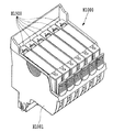
図35、36、および37は、本発明に係る液体吐出記録ヘッドの第4実施例を示す。
【0183】
図35〜37においては、図11に示される例において流路形成部材H1600における連通路H1600dの開口端の配列は、一直線上に所定の間隔で配列されているが、その代わりに、流路形成部材H1600‘における連通路H1600d’の開口端の配列が千鳥掛け状となるように配列される。
【0184】
なお、図35〜37においては、図11において同一とされる構成要素については同一の符号を付して示し、その重複説明を省略する。
【0185】
ホルダーH1500における流路形成部材H1600’が挿入され固定される部分には、一端が上述のインク供給孔H1520に連通し、他端が流路形成部材H1600’のインク流路の開口端に対応して形成される溝状のインク流路H1521‘がそれぞれ、各インクタンクH1900に対応して形成されている。従って、各インク流路H1521’の他端の相互間隔が、一端の相互間隔に比して小となるように、各インク流路H1521の他端は、流路形成部材H1600のインク流路の開口端に対応して千鳥掛け状に集合している。
【0186】
各インク流路H1521‘は、流路形成部材H1600’の当接面に接合されることにより、各インクタンクH1900からの各インクをそれぞれ流路形成部材H1600‘の各インク流路に供給するインク供給路が形成されることとなる。
【0187】
また、相対向する突起片H1600aと突起片H1600bとの間には、図35および図38の(A)および(B)に示されるように、第1のプレートH1200‘の各インク供給口H1201’、および、上述の各インク流路H1521‘の他端にそれぞれ対応して連通孔H1600d’が所定の相互間隔で互いに平行に千鳥掛け状に形成されている。各連通孔H1600d‘の開口端部において、第1のプレートH1200’が接着される側の周縁には、円形状の縁H1600e‘がそれぞれ他の部分に対して隆起して形成されている。各縁H1600e’は、第1のプレートH1200‘と接合されるとき、第1のプレートH1200’の各インク供給口H1201‘に係合するものとされる。即ち、各連通孔H1600d’は、第1のプレートH1200‘内に連通されることとなる。
【0188】
また、第1のプレートH1200‘は、図35に示されるように,流路形成部材H1600’からの6色のインクをそれぞれ記録素子基板H1100に供給するための6つのインク供給口H1201‘が、上述の各連通孔H1600d‘に対応して千鳥掛け状に形成されている。なお、各インク供給口H1201‘は、上述の図33の(B)に示されるように,記録素子基板H1100が接着される端面H1200sに向けて開口するインク流路としての拡大部H1202にそれぞれ連通している。
【0189】
従って、各連通孔H1600d‘およびインク供給口H1201’を2列の千鳥配列にすることにより、インク供給口間の配列ピッチを広げたり、またインク供給口を小さくすることなしにインク供給口周囲に溝や段差形状を設け、かつ十分な接着領域を確保することが可能となる。その結果、インク漏れ等を引き起こさない、信頼性の高い、コンパクトなインクジェット記録ヘッドが提供できることとなる。
【0190】
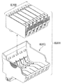
図38、39、および40は、本発明に係る液体吐出記録ヘッドの第5実施例を示す。
【0191】
なお、図38〜40においては、図2および図13の(A)において同一とされる構成要素については同一の符号を付して示し、その重複説明を省略する。
【0192】
上述の例においては、記録ヘッドH1001としてホルダーH1500にインクタンクH1900が装着される構成を用いて説明したが、しかし、かかる構成に限定されるものではなく,上述のような記録素子部とタンク部とが一体的な構成である一般的にディスポ−ザブルヘッドと呼ばれている記録ヘッドに対し本発明が適用されてもよいことは勿論である。
【0193】
図39に示される例においては、記録ヘッドH1004に対し複数の互いに異なるインク色のインクをそれぞれ供給するインクタンクH2000A、H2000B,H2000C,H2000D,H2000E,および、H2000FをキャリッジM4001とは別に装置本体M1000側に備えている。インクタンクH2000A〜H2000Fは、例えば、キャリッジM4001の移動路の下方となる位置に配されている。図39においては、インクタンクH2000D,H2000E,および、H2000Fの図示は省略されている。
【0194】
インクタンクH2000A〜H2000Fは、それぞれ、一端が接続される複数のインク供給チューブからなるインクチューブ群H2010を通じてキャリッジM4001に搭載される記録ヘッドH1004に、貯留されるインクを供給するものとされる。各インクは、記録ヘッドH1004の記録動作に応じて発生する記録ヘッドH1004内の負圧もしくは毛管力により自動的に導かれる。
【0195】
記録ヘッドH1004は、図40に示されるように、記録素子ユニットH1002と、その記録素子ユニットH1002を保持するとともに、供給される各インクがそれぞれ貯留される共通インク室を有するホルダーH1550とを含んで構成されている。
【0196】
ホルダーH1550の共通インク室は、それぞれ、インクチューブ群H2010の他端に接続されている。
【0197】
ホルダーH1550は、外部信号入力端子H1301が位置決め固定される背面側の下端部に、基準端面部H1550aおよび1550bを有している。基準端面部H1550aおよび1550bは、それぞれ、その周縁に形成される切欠き部H1550SaおよびH1550Sbを通じて側方に連通している。
【0198】
また、ホルダーH1550は、図40および図41に示されるように、組み合わされる第1のプレートH1200に対向する面側に、第1のプレートH1200の両端部を挟持する突起片H1550GaおよびH1550Gbを有している。
【0199】
その際、ホルダーH1550の突起片H1550GaおよびH1550GbとホルダーH1550の基準端面部H1550aおよび1550bとの間には、第1のプレートH1200の突起部H1200Aがそれぞれ係合される所定の隙間が形成されることなる。
【0200】
また、ホルダーH1550の基準端面部H1550aおよび1550bは、それぞれ、係合部M4002aの係合面に当接されることとなる。従って、装着されたホルダーH1550における記録素子基板H1100の吐出口H1100T列は、キャリッジM4002の移動方向に対し所定の角度をなしてキャリッジM4002に精度よく位置決めされることとなる。
【0201】
【発明の効果】
以上の説明から明らかなように、本発明によれば、ホルダーにおけるキャリッジとの位置決め部は、支持体とホルダーとの位置決め部をかねているという基本的構成を有するので,キャリッジ部材に対する記録素子基板の位置決め精度を簡易な構造で向上させることができる。
【図面の簡単な説明】
【図1】本発明の一実施例によるインクジェットプリンタの外観構成を示す斜視図である。
【図2】図1に示すプリンタの外装部材を取り外した状態を示す斜視図である。
【図3】本発明の一実施例によるプリンタに用いる記録ヘッドカートリッジを組立てた状態を示す斜視図である。
【図4】図3に示す記録ヘッドカートリッジを示す分解斜視図である。
【図5】図4に示した記録ヘッドを斜め下方から観た分解斜視図である。
【図6】(a)および(b)は、それぞれ、図3の記録ヘッドカートリッジに代えて本発明の一実施例によるプリンタに搭載可能なスキャナカートリッジの構成を示すために、そのスキャナカートリッジを天地逆にして示す斜視図である。
【図7】本発明の一実施例のプリンタにおける電気的回路の全体構成を概略的に示すブロック図である。
【図8】図7に示した電気回路のうちメインPCBの内部構成例を示すブロック図である。
【図9】図8に示したメインPCBのうちASICの内部構成例を示すブロック図である。
【図10】本発明の一実施例のプリンタの動作例を示すフローチャートである。
【図11】図4に示した記録ヘッドを斜め下方から観た分解斜視図である。
【図12】本発明に係る液体吐出記録ヘッドの第1の実施例を、それが適用された記録装置の一部とともに示す斜視図である。
【図13】(A)は、図12に示される例において装着された液体吐出記録ヘッドの要部を示す平面図である。(B),(C)は、それぞれ、図12に示される例における記録素子基板の組み立ての説明に供される図である。
【図14】図12に示される例における組み立ての説明に供される斜視図である。
【図15】図12に示される例における組み立ての説明に供される斜視図である。
【図16】本発明に係る液体吐出記録ヘッドを備える記録装置の一例としてのインクジェットプリンタのキャリッジを示す斜視図である。
【図17】本発明に係る液体吐出記録ヘッドの第2の実施例を示す斜視図である。
【図18】図17に示される例において装着された液体吐出記録ヘッドを示す平面図である。
【図19】本発明に係る液体吐出記録ヘッドの第3の実施例の要部を示す平面図である。
【図20】図19におけるXX−XX線に沿って示される部分断面図である。
【図21】従来のホルダーおよび記録素子基板を示す斜視図である。
【図22】従来のホルダーおよび記録素子基板の組み立てについての説明に供される斜視図である。
【図23】図21に示されるインクカートリッジがキャリッジ内に装着された状態を示す斜視図である。
【図24】本発明の実施例に用いる記録素子ユニットを組立てた状態をホルダーとともに示す分解斜視図である。
【図25】本発明の実施例に用いる記録素子ユニットおよびホルダーユニットを示す分解斜視図である。
【図26】本発明に係る液体吐出記録ヘッドの各実施例の一部を構成する記録素子基板を示す斜視図である。
【図27】本発明の実施例に用いるインクタンクを、記録ヘッドとともに示す斜視図である。
【図28】インクタンクが図27に示されるホルダー内に装着された状態をあらわす断面図である。
【図29】本発明に係る液体吐出記録ヘッドの各実施例の一部を構成するホルダーの正面図である。
【図30】図29に示される例におけるホルダーの平面図である。
【図31】図26に示される例におけるオリフィスプレートの内部を示す部分断面図である。
【図32】(A)は、図11に示される例における第1のプレートの平面図であり、(B)は、図11に示される例における第1のプレートの側面図である。
【図33】(A)および(B)は、それぞれ、図32の(A)に示される第1のプレートの部分断面図である。(C)は、比較例としてのプレートの説明に供される部分断面図である。
【図34】(A)は、図11に示される例において流路形成部材の連通路を示す平面図である。(B)は、(A)に示される部分における部分断面図である。
【図35】本発明に係る液体吐出記録ヘッドの第4実施例を示す分解斜視図である。
【図36】図35に示される例において流路形成部材がホルダーに固定され、第1のプレートが電気配線基板に組み付けられた状態を示す分解斜視図である。
【図37】図37は、図35に示される例における第1のプレートの平面図である。
【図38】(A)は、図35に示される例において流路形成部材の連通路を示す平面図である。(B)は、(A)に示される一部分における部分断面図である。
【図39】本発明に係る液体吐出記録ヘッドの第5実施例を、それが適用された記録装置とともに示す斜視図である。
【図40】図39に示される例に用いられる液体吐出記録ヘッドを示す斜視図である。
【図41】図39に示される例において装着された液体吐出記録ヘッドの要部を示す平面図である。
【符号の説明】
M1000 装置本体
M1001 下ケース
M1002 上ケース
M1003 アクセスカバー
M1004 排出トレイ
M2015 紙間調整レバー
M2003 排紙ローラ
M3001 LFローラ
M3019 シャーシ
M3022 自動給送部
M3029 搬送部
M3030 排出部
M4000 記録部
M4001 キャリッジ
M4002 キャリッジカバー
M4007 ヘッドセットレバー
M4021 キャリッジ軸
M5000 回復系ユニット
M6000 スキャナ
M6001 スキャナホルダ
M6003 スキャナカバー
M6004 スキャナコンタクトPCB
M6005 スキャナ照明レンズ
M6006 スキャナ読取レンズ1
M6100 保管箱
M6101 保管箱ベース
M6102 保管箱カバー
M6103 保管箱キャップ
M6104 保管箱バネ
E0001 キャリッジモータ
E0002 LFモータ
E0003 PGモータ
E0004 エンコーダセンサ
E0005 エンコーダスケール
E0006 インクエンドセンサ
E0007 PEセンサ
E0008 GAPセンサ(紙間センサ)
E0009 ASFセンサ
E0010 PGセンサ
E0011 コンタクトFPC(フレキシブルプリントケーブル)
E0012 CRFFC(フレキシブルフラットケーブル)
E0013 キャリッジ基板
E0014 メイン基板
E0015 電源ユニット
E0016 パラレルI/F
E0017 シリアルI/F
E0018 電源キー
E0019 リジュームキー
E0020 LED
E0021 ブザー
E0022 カバーセンサ
E1001 CPU
E1002 OSC(CPU内蔵オシレータ)
E1003 A/D(CPU内蔵A/Dコンバータ)
E1004 ROM
E1005 発振回路
E1006 ASIC
E1007 リセット回路
E1008 CRモータドライバ
E1009 LF/PGモータドライバ
E1010 電源制御回路
E1011 INKS(インクエンド検出信号)
E1012 TH(サーミスタ温度検出信号)
E1013 HSENS(ヘッド検出信号)
E1014 制御バス
E1015 RESET(リセット信号)
E1016 RESUME(リジュームキー入力)
E1017 POWER(電源キー入力)
E1018 BUZ(ブザー信号)
E1019 発振回路出力信号
E1020 ENC(エンコーダ信号)
E1021 ヘッド制御信号
E1022 VHON(ヘッド電源ON信号)
E1023 VMON(モータ電源ON信号)
E1024 電源制御信号
E1025 PES(PE検出信号)
E1026 ASFS(ASF検出信号)
E1027 GAPS(GAP検出信号)
E0028 シリアルI/F信号
E1029 シリアルI/Fケーブル
E1030 パラレルI/F信号
E1031 パラレルI/Fケーブル
E1032 PGS(PG検出信号)
E1033 PM制御信号(パルスモータ制御信号)
E1034 PGモータ駆動信号
E1035 LFモータ駆動信号
E1036 CRモータ制御信号
E1037 CRモータ駆動信号
E0038 LED駆動信号
E1039 VH(ヘッド電源)
E1040 VM(モータ電源)
E1041 VDD(ロジック電源)
E1042 COVS(カバー検出信号)
E2001 CPU I/F
E2002 PLL
E2003 DMA制御部
E2004 DRAM制御部
E2005 DRAM
E2006 1284 I/F
E2007 USB I/F
E2008 受信制御部
E2009 圧縮・伸長DMA
E2010 受信バッファ
E2011 ワークバッファ
E2012 ワークエリアDMA
E2013 記録バッファ転送DMA
E2014 プリントバッファ
E2015 記録データ展開DMA
E2016 展開用データバッファ
E2017 カラムバッファ
E2018 ヘッド制御部
E2019 エンコーダ信号処理部
E2020 CRモータ制御部
E2021 LF/PGモータ制御部
E2022 センサ信号処理部
E2023 モータ制御バッファ
E2024 スキャナ取込みバッファ
E2025 スキャナデータ処理DMA
E2026 スキャナデータバッファ
E2027 スキャナデータ圧縮DMA
E2028 送出バッファ
E2029 ポート制御部
E2030 LED制御部
E2031 CLK(クロック信号)
E2032 PDWM(ソフト制御信号)
E2033 PLLON(PLL制御信号)
E2034 INT(割り込み信号)
E2036 PIF受信データ
E2037 USB受信データ
E2038 WDIF(受信データ/ラスタデータ)
E2039 受信バッファ制御部
E2040 RDWK(受信バッファ読み出しデータ/ラスタデータ)
E2041 WDWK(ワークバッファ書込みデータ/記録コード)
E2042 WDWF(ワークフィルデータ)
E2043 RDWP(ワークバッファ読み出しデータ/記録コード)
E2044 WDWP(並べ替え記録コード)
E2045 RDHDG(記録展開用データ)
E2047 WDHDG(カラムバッファ書込みデータ/展開記録データ)
E2048 RDHD(カラムバッファ読み出しデータ/展開記録データ)
E2049 ヘッド駆動タイミング信号
E2050 データ展開タイミング信号
E2051 RDPM(パルスモータ駆動テーブル読み出しデータ)
E2052 センサ検出信号
E2053 WDHD(取込みデータ)
E2054 RDAV(取込みバッファ読み出しデータ)
E2055 WDAV(データバッファ書込みデータ/処理済データ)
E2056 RDYC(データバッファ読み出しデータ/処理済データ)
E2057 WDYC(送出バッファ書込みデータ/圧縮データ)
E2058 RDUSB(USB送信データ/圧縮データ)
E2059 RDPIF(1284送信データ)
H1000 記録ヘッドカートリッジ
H1001 記録ヘッド
H1100 記録素子基板
H1100T 吐出口
H1200 第1のプレート
H1201 インク供給口
H1300 電気配線基板
H1301 外部信号入力端子
H1400 第2のプレート
H1500,H1550 ホルダー
H1501 インク流路
H1600 流路形成部材
H1700 フィルター
H1800 シールゴム
H1900,H2000A,H2000B,H2000C インクタンク
H1200A 突起部
H1200a、H1200a’ 係合面部
H1502a 基準端面部
H1505 押圧片
M4002a 係合部
H1200’ 第1のプレート
H1200b’ 透孔
H1500s 雌ねじ孔
Bs 皿ビス
Ba 座面部
H1600d,H1600d’ 連通路[0001]
BACKGROUND OF THE INVENTION
The present invention relates to a liquid discharge recording head,and,Recording device provided with the sameInRelated. In addition to a general printing apparatus, the present invention is an apparatus such as a copying machine, a facsimile having a communication system, a word processor having a printing unit, and an industrial recording apparatus combined with various processing apparatuses. Can be applied.
[0002]
[Prior art]
Inkjet recording apparatuses have been put to practical use as recording apparatuses that perform a recording operation on the recording surface of a recording medium. In general, an ink jet recording apparatus includes an ink cartridge having a recording head that ejects ink onto a recording surface of a recording medium, as also shown in FIGS.
[0003]
As shown in FIGS. 22 and 23, the ink cartridge includes
[0004]
The
[0005]
For example, as shown in an enlarged view in FIG. 21, the
[0006]
A
[0007]
[0008]
Furthermore, on the
[0009]
The
[0010]
The
[0011]
In forming the pixel at a predetermined position on the recording surface of the recording medium while moving in the direction indicated by the arrow S, the ink
[0012]
Accordingly, when positioning and fixing the
[0013]
Next, in positioning the ink
[0014]
[Problems to be solved by the invention]
However, as described above, the positioning of the
[0015]
The present invention relates to a liquid discharge recording head capable of improving the positioning accuracy of a recording element substrate with respect to a carriage member with a simple mechanism,and,Recording equipment equipped with itPlaceThe main purpose is to provide
[0016]
[Means for Solving the Problems]
In order to achieve the above object, a liquid discharge recording head according to the present invention includes a plurality of recording element substrates having recording elements for discharging liquid, a support that supports the recording element substrate, and a support. A liquid ejection recording head comprising: a carriage that moves with the holder; and a holder that includes a positioning unit that positions the holders, wherein the positioning unit in the holder includes a support and It also serves as a positioning part for positioning between the holders.
[0017]
The recording apparatus according to the present invention includes a liquid discharge recording head that performs recording by discharging liquid, and a liquid discharge recording head.MoveCarriage toWhenThe liquid discharge recording head includes a plurality of recording element substrates having recording elements for discharging liquid, a support that supports the recording element substrate, and a support.A holder, the holderWithMoveDoPosition between the carriage and holderA holder having a positioning portion, and the positioning portion in the holder isPositioning between support and holderIt also serves as a positioning part.
[0019]
DETAILED DESCRIPTION OF THE INVENTION
Hereinafter, an embodiment of a recording apparatus including a liquid discharge recording head according to the present invention will be described with reference to the drawings.
[0020]
In the embodiments described below, a printer is taken as an example of a recording apparatus using an inkjet recording method.
[0021]
In this specification, “print” (sometimes referred to as “recording”) is not only for forming significant information such as characters and figures, but also for human beings visually perceived regardless of significance. Regardless of whether or not it has been manifested, it also refers to a case where an image, a pattern, a pattern, or the like is widely formed on a print medium or the medium is processed.
[0022]
Here, “print medium” refers not only to paper used in general printing apparatuses, but also to materials that can accept ink, such as cloth, plastic film, metal plate, glass, ceramics, wood, leather, etc. Shall also say.
[0023]
Further, “ink” (sometimes referred to as “liquid”) is to be interpreted widely as the definition of “print” above, and it is applied to a print medium so that an image, a pattern, a pattern, etc. It shall refer to a liquid that can be subjected to formation or processing of the print medium, or ink processing (eg, solidification or insolubilization of the colorant in the ink applied to the print medium).
[0024]
[Device main unit]
1 and 2 show a schematic configuration of a printer using the ink jet recording method. In FIG. 1, the printer main body M1000 in this embodiment includes an exterior member including a lower case M1001, an upper case M1002, an access cover M1003, and a discharge tray M1004, and a chassis M3019 (see FIG. 1) housed in the exterior member. 2).
[0025]
The chassis M3019 is composed of a plurality of plate-shaped metal members having a predetermined rigidity, forms a skeleton of the recording apparatus, and holds each recording operation mechanism described later.
The lower case M1001 forms a substantially lower half part of the exterior of the apparatus main body M1000, and the upper case M1002 forms a substantially upper half part of the exterior of the apparatus main body M1000. A hollow body structure having a storage space for storing the mechanism is formed. An opening is formed in each of the upper surface portion and the front surface portion of the apparatus main body M1000.
[0026]
Further, one end of the discharge tray M1004 is rotatably held by the lower case M1001, and the opening formed on the front surface of the lower case M1001 can be opened and closed by the rotation. For this reason, when executing the recording operation, the discharge tray M1004 is rotated to the front side to open the opening so that the recording sheets can be discharged and the discharged recording sheets P are sequentially stacked. It has come to be able to do. In addition, the discharge tray M1004 contains two auxiliary trays M1004a and M1004b. By pulling out each tray as needed, the sheet support area can be expanded or reduced in three stages. It has become.
[0027]
One end of the access cover M1003 is rotatably held by the upper case M1002, and can open and close an opening formed on the upper surface. By opening the access cover M1003, the access cover M1003 is housed inside the main body. It is possible to replace the print head cartridge H1000 or the ink tank H1900. Although not specifically shown here, when the access cover M1003 is opened and closed, the protrusion formed on the back surface rotates the cover opening and closing lever, and the rotation position of the lever is detected by a micro switch or the like. Thus, the open / closed state of the access cover can be detected.
[0028]
On the upper surface of the rear part of the upper case M1002, a power key E0018 and a resume key E0019 are provided so that they can be pressed, and an LED E0020 is provided. When the power key E0018 is pressed, the LED E0020 lights up and recording is possible. This is to inform the operator. Further, the LED E0020 has various display functions such as blinking method and color change, and informing the operator of printer troubles. Further, the buzzer E0021 (FIG. 7) can be leveled. When the trouble is solved, the recording is resumed by pressing the resume key E0019.
[0029]
[Recording mechanism]
Next, the recording operation mechanism in the present embodiment that is housed and held in the printer apparatus main body M1000 will be described.
[0030]
As a recording operation mechanism in the present embodiment, an automatic feeding unit M3022 that automatically feeds the recording sheet P into the apparatus main body, and a recording sheet P that is sent one by one from the automatic feeding unit are recorded in a predetermined manner. A conveyance unit M3029 for guiding the recording sheet P from the recording position to the discharge unit M3030, a recording unit for performing desired recording on the recording sheet P conveyed to the recording position, and a recovery process for the recording unit And a recovery unit (M5000).
[0031]
(Recording part)
Here, the recording unit will be described. The recording unit includes a carriage M4001 that is movably supported by a carriage shaft M4021, and a recording head cartridge H1000 that is detachably mounted on the carriage M4001.
[0032]
Recording head cartridge
First, a recording head cartridge used in the recording unit will be described with reference to FIGS.
[0033]
The recording head cartridge H1000 in this embodiment includes an ink tank H1900 that stores ink and a recording head H1001 that ejects ink supplied from the ink tank H1900 from nozzles according to recording information, as shown in FIG. . The recording head H1001 adopts a so-called cartridge system that is detachably mounted on a carriage M4001 described later.
[0034]
The recording head cartridge H1000 shown here is provided with ink tanks H1900 that are independent of each color of black, light cyan, light magenta, cyan, magenta, and yellow, for example, in order to enable high-quality color recording with photographic tone. As shown in FIG. 4, each is detachable from the recording head H1001.
[0035]
As shown in the exploded perspective view of FIG. 5, the recording head H1001 includes a recording element substrate H1100, a first plate H1200, an electric wiring substrate H1300, a second plate H1400, a holder H1500, a flow path forming member H1600, a filter. It consists of H1700 and seal rubber H1800.
[0036]
In the recording element substrate H1100, a plurality of recording elements for ejecting ink to one side of the Si substrate and electric wiring such as Al for supplying power to each recording element are formed by a film forming technique. A plurality of corresponding ink channels and a plurality of ejection ports H1100T are formed by photolithography, and ink supply ports for supplying ink to the plurality of ink channels are formed to open on the back surface. . The recording element substrate H1100 is bonded and fixed to the first plate H1200, and an ink supply port H1201 for supplying ink to the recording element substrate H1100 is formed therein. Further, a second plate H1400 having an opening is bonded and fixed to the first plate H1200, and the electric wiring substrate H1300 is electrically connected to the recording element substrate H1100 via the second plate H1400. Is held to be connected. The electrical wiring board H1300 applies an electrical signal for ejecting ink to the recording element substrate H1100. The electrical wiring board H1300 is located at the end of the electrical wiring and corresponds to the electrical wiring from the main body. It has an external signal input terminal H1301 for receiving a signal, and the external signal input terminal H1301 is positioned and fixed on the back side of a holder H1500 described later.
[0037]
On the other hand, in the holder H1500 that detachably holds the ink tank H1900, a flow path forming member H1600 is fixed by, for example, ultrasonic welding to form an ink flow path H1501 extending from the ink tank H1900 to the first plate H1200. Yes. In addition, a filter H1700 is provided at the end of the ink flow path H1501 that engages with the ink tank H1900 on the ink tank side so as to prevent dust from entering from the outside. Further, a seal rubber H1800 is attached to the engaging portion with the ink tank H1900 so that ink can be prevented from evaporating from the engaging portion.
[0038]
Further, as described above, the holder portion composed of the holder H1500, the flow path forming member H1600, the filter H1700, and the seal rubber H1800, the recording element substrate H1100, the first plate H1200, the electric wiring substrate H1300, and the second plate H1400. The recording head unit H1001 is configured by bonding the recording element unit constituted by the above by bonding or the like.
[0039]
(carriage)
Next, the carriage M4001 on which the recording head cartridge H1000 is mounted will be described with reference to FIG.
[0040]
As shown in FIG. 2, for example, a carriage M4001 formed of a resin material includes a carriage cover M4002 that engages with the carriage M4001 and guides the recording head H1001 to a predetermined mounting position on the carriage M4001, and a recording head. A head set lever M4007 that engages with the holder H1500 of the H1001 and presses the recording head H1001 to be set at a predetermined mounting position is provided.
That is, the head set lever M4007 is provided on the upper portion of the carriage M4001 so as to be rotatable with respect to the head set lever shaft, and a spring-set head set plate (not shown) is engaged with the recording head H1001. And is configured to be mounted on the carriage M4001 while pressing the recording head H1001 by this spring force.
[0041]
Further, a contact flexible printed cable (see FIG. 7, hereinafter referred to as a contact FPC) E0011 is provided at another engagement portion of the carriage M4001 with the recording head H1001, and the contact portion on the contact FPC E0011 and the recording head H1001 are provided. The provided contact portion (external signal input terminal) H1301 is in electrical contact so that various information for recording can be exchanged and power can be supplied to the recording head H1001.
[0042]
Here, an elastic member such as rubber (not shown) is provided between the contact portion of the contact FPC E0011 and the carriage M4001, and the contact portion and the carriage M4001 are connected by the elastic force of the elastic member and the pressing force by the headset lever spring. It is designed to enable reliable contact. Further, the contact FPC E0011 is connected to a carriage substrate E0013 mounted on the back surface of the carriage M4001 (see FIG. 7).
[0043]
[Scanner]
The printer in this embodiment can also be used as a reading device by mounting a scanner on the carriage M4001 instead of the recording head cartridge H1000 described above.
[0044]
This scanner moves in the main scanning direction together with the carriage M4001 on the printer side, and reads the original image fed instead of the recording medium in the course of movement in the main scanning direction. By alternately performing the reading operation and the document feeding operation in the sub-scanning direction, it is possible to read one document image information.
[0045]
FIGS. 6A and 6B are diagrams showing the scanner M6000 upside down in order to explain the schematic configuration of the scanner M6000.
[0046]
As shown in the figure, the scanner holder M6001 has a substantially box shape, and an optical system and a processing circuit necessary for reading are accommodated therein. Further, when the scanner M6000 is mounted on the carriage M4001, a reading unit lens M6006 is provided in a portion facing the document surface, and reflected light from the document surface is converged on the internal reading unit by the lens M6006. Therefore, the original image is read. On the other hand, the illumination unit lens M6005 has a light source (not shown) inside, and light emitted from the light source is irradiated onto the document through the lens M6005.
[0047]
A scanner cover M6003 fixed to the bottom of the scanner holder M6001 is fitted so as to shield the inside of the scanner holder M6001, and a louver-shaped grip portion provided on the side surface improves the detachable operability to the carriage M4001. Yes. The outer shape of the scanner holder M6001 is substantially the same as that of the recording head H1001, and it can be attached to and detached from the carriage M4001 by the same operation as that of the recording head cartridge H1000.
[0048]
The scanner holder M6001 accommodates a substrate having a reading processing circuit, and a scanner contact PCB connected to the substrate is exposed to the outside. When the scanner M6000 is mounted on the carriage M4001, The scanner contact PCB M6004 contacts the contact FPC E0011 on the carriage M4001 side, and the substrate is electrically connected to the control system on the main body side via the carriage M4001.
[0049]
[Configuration of printer electrical circuit]
Next, an electrical circuit configuration in the embodiment of the present invention will be described.
FIG. 7 is a diagram schematically showing an example of the overall configuration of the electrical circuit in this embodiment.
[0050]
The electrical circuit in this embodiment is mainly configured by a carriage substrate (CRPCB) E0013, a main PCB (Printed Circuit Board) E0014, a power supply unit E0015, and the like.
Here, the power supply unit E0015 is connected to the main PCB E0014 and supplies various driving powers.
The carriage substrate E0013 is a printed circuit board unit mounted on the carriage M4001 (FIG. 2). The carriage substrate E0013 functions as an interface for exchanging signals with the recording head through the contact FPC E0011. Based on the pulse signal output from the sensor E0004, a change in the positional relationship between the encoder scale E0005 and the encoder sensor E0004 is detected, and the output signal is output to the main PCB E0014 through a flexible flat cable (CRFFC) E0012.
[0051]
Further, the main PCBE0014 is a printed circuit board unit that controls driving of each part of the ink jet recording apparatus in this embodiment, and includes a paper edge detection sensor (PE sensor) E0007, an ASF (automatic paper feeder) sensor E0009, a cover sensor E0022, a parallel sensor. The board has I / O ports for an interface (parallel I / F) E0016, a serial interface (serial I / F) E0017, a resume key E0019, an LED E0020, a power key E0018, a buzzer E0021, and the like. Still further, a motor (CR motor) E0001 that serves as a drive source for main-scanning the carriage M1400, a motor (LF motor) E0002 that serves as a drive source for transporting the recording medium, the rotation operation of the recording head, and the recording medium In addition to being connected to a motor (PG motor) E0003 that is also used for paper feeding operation to control these driving, it has a connection interface with ink empty sensor E0006, GAP sensor E0008, PG sensor E0010, CRFFC E0012, and power supply unit E0015. .
[0052]
FIG. 8 is a block diagram showing the internal configuration of the main PCB E0014. In the figure, E1001 is a CPU, and this CPU E1001 has a clock generator (CG) E1002 connected to an oscillation circuit E1005 inside, and generates a system clock by its output signal E1019. Further, it is connected to a ROM E1004 and an ASIC (Application Specific Integrated Circuit) E1006 through a control bus E1014, and controls the ASIC E1006, an input signal E1017 from the power key, and an input signal E1016 from the resume key according to a program stored in the ROM. Ink empty detection signal connected to the built-in A / D converter E1003 by detecting the state of the cover detection signal E1042 and the head detection signal (HSENS) E1013 and further driving the buzzer E0021 by the buzzer signal (BUZ) E1018. While detecting the state of the temperature detection signal (TH) E1012 by the (INKS) E1011 and the thermistor, it performs various other logical operations and condition determinations and controls the drive of the ink jet recording apparatus.
[0053]
Here, the head detection signal E1013 is a head mounting detection signal input from the recording head cartridge H1000 via the flexible flat cable E0012, the carriage substrate E0013, and the contact flexible print cable E0011, and the ink empty detection signal E1011 is an ink empty sensor. An analog signal output from E0006 and a temperature detection signal E1012 are analog signals from a thermistor (not shown) provided on the carriage substrate E0013.
[0054]
E1008 is a CR motor driver, which uses a motor power source (VM) E1040 as a drive source, generates a CR motor drive signal E1037 in accordance with a CR motor control signal E1036 from the ASIC E1006, and drives the CR motor E0001. E1009 is an LF / PG motor driver, which uses a motor power source E1040 as a drive source, generates an LF motor drive signal E1035 according to a pulse motor control signal (PM control signal) E1033 from the ASIC E1006, and drives the LF motor thereby At the same time, a PG motor drive signal E1034 is generated to drive the PG motor.
[0055]
E1010 is a power supply control circuit that controls power supply to each sensor having a light emitting element in accordance with a power supply control signal E1024 from the ASIC E1006. The parallel I / F E0016 transmits the parallel I / F signal E1030 from the ASIC E1006 to the parallel I / F cable E1031 connected to the outside, and transmits the signal of the parallel I / F cable E1031 to the ASIC E1006. The serial I / F E0017 transmits the serial I / F signal E1028 from the ASIC E1006 to the serial I / F cable E1029 connected to the outside, and transmits the signal from the cable E1029 to the ASIC E1006.
[0056]
On the other hand, a head power supply (VH) E1039, a motor power supply (VM) E1040, and a logic power supply (VDD) E1041 are supplied from the power supply unit E0015. Also, a head power ON signal (VHON) E1022 and a motor power ON signal (VMOM) E1023 from the ASIC E1006 are input to the power supply unit E0015, and control ON / OFF of the head power E1039 and the motor power E1040, respectively. The logic power supply (VDD) E1041 supplied from the power supply unit E0015 is voltage-converted as necessary, and then supplied to each part inside and outside the main PCB E0014.
[0057]
The head power signal E1039 is smoothed on the main PCB E0014 and then sent to the flexible flat cable E0011 to be used for driving the recording head cartridge H1000.
[0058]
E1007 is a reset circuit that detects a decrease in the logic power supply voltage E1041, supplies a reset signal (RESET) E1015 to the CPU E1001 and the ASIC E1006, and performs initialization.
[0059]
The ASIC E1006 is a one-chip semiconductor integrated circuit and is controlled by the CPU E1001 through the control bus E1014. The above-described CR motor control signal E1036, PM control signal E1033, power supply control signal E1024, head power supply ON signal E1022, and motor power supply The ON signal E1023 and the like are output to exchange signals with the parallel I / F E0016 and the serial I / F E0017, as well as the PE detection signal (PES) E1025 from the PE sensor E0007, and the ASF detection signal from the ASF sensor E0009 ( ASFS) E1026, GAP detection signal (GAPS) E1027 from sensor (GAP) sensor E0008 for detecting the gap between the recording head and the recording medium, PG detection signal (PGS) E10 from PG sensor E0010 Detects the second state, and transmitted to the CPU E1001 through the control bus E1014 data representing the state, CPU E1001 based on the input data performs a flashing LEDE0020 controls the driving of an LED drive signal E1038.
[0060]
Further, the state of the encoder signal (ENC) E1020 is detected to generate a timing signal, and the head control signal E1021 is used to interface with the printhead cartridge H1000 to control the printing operation. Here, the encoder signal (ENC) E1020 is an output signal of the CR encoder sensor E0004 inputted through the flexible flat cable E0012. The head control signal E1021 is supplied to the recording head H1000 via the flexible flat cable E0012, the carriage substrate E0013, and the contact FPC E0011.
[0061]
FIG. 9 is a block diagram showing an example of the internal configuration of ASIC E1006.
[0062]
In the figure, the connection between each block shows only the flow of data related to the control of the head and each mechanism component, such as recording data and motor control data. Such control signals, clocks, and control signals related to DMA control are omitted in order to avoid complications described in the drawings.
[0063]
In FIG. 9, reference numeral E2002 denotes a PLL controller. As shown in FIG. 9, a clock (CLK) E2031 and a PLL control signal (PLLON) E2033 output from the CPU E1001 are supplied to most of the ASIC E1006. (Not shown).
[0064]
Reference numeral E2001 denotes a CPU interface (CPU I / F). The reset signal E1015, a soft reset signal (PDWN) E2032 output from the CPU E1001, a clock signal (CLK) E2031, and a control signal from the control bus E1014 Controls register read / write for each block as described, supplies clocks to some blocks, accepts interrupt signals (not shown), and outputs an interrupt signal (INT) E2034 to the CPU E1001 Then, the occurrence of an interrupt in the ASIC E1006 is notified.
[0065]
Reference numeral E2005 denotes a DRAM having areas such as a reception buffer E2010, a work buffer E2011, a print buffer E2014, and a development data buffer E2016 as recording data buffers, and a motor control buffer E2023 for motor control. Furthermore, the buffer used in the scanner operation mode has areas such as a scanner take-in buffer E2024, a scanner data buffer E2026, and a send buffer E2028 that are used in place of the recording data buffers.
[0066]
The DRAM E2005 is also used as a work area necessary for the operation of the CPU E1001. That is, E2004 is a DRAM control unit, which switches between access from the CPU E1001 to the DRAM E2005 by the control bus and access from the DMA control unit E2003 to the DRAM E2005, which will be described later, and performs a read / write operation to the DRAM E2005.
[0067]
The DMA control unit E2003 receives a request (not shown) from each block, and in the case of a write operation, an address signal or a control signal (not shown), and write data E2038, E2041, E2044, E2053, E2055, E2057. Are output to the DRAM control unit E2004 to access the DRAM. In the case of reading, read data E2040, E2043, E2045, E2051, E2054, E2056, E2058, and E2059 from the DRAM control unit E2004 are transferred to the request source block.
[0068]
E2006 is an IEEE 1284 I / F, which performs a bidirectional communication interface with an external host device (not shown) through a parallel I / F E0016 under the control of the CPU E1001 via the CPU I / F E2001. Data received from the I / F E0016 (PIF reception data E2036) is transferred to the reception control unit E2008 by DMA processing, and data stored in the transmission buffer E2028 in the DRAM E2005 when reading the scanner (1284 transmission data (RDPIF) E2059) Is transmitted to the parallel I / F by DMA processing.
[0069]
E2007 is a universal serial bus (USB) I / F, and performs a bidirectional communication interface with an external host device (not shown) through the serial I / F E0017 under the control of the CPU E1001 via the CPU I / F E2001. The received data (USB received data E2037) from the serial I / F E0017 is transferred to the reception control unit E2008 by DMA processing at the time of printing, and the data (USB transmitted data (RDUSB) stored in the transmission buffer E2028 in the DRAM E2005 is read by the scanner. E2058) is transmitted to the serial I / F E0017 by DMA processing. The reception control unit E2008 writes the reception data (WDIF) E2038) from the I / F selected from the 1284 I / F E2006 or USB I / F E2007 to the reception buffer write address managed by the reception buffer control unit E2039. Include.
[0070]
E2009 is a compression / decompression DMA controller, which receives received data (raster data) stored in the receiving buffer E2010 under the control of the CPU E1001 via the CPU I / F E2001, and receives the received buffer read address managed by the received buffer control unit E2039. The data (RDWK) E2040 is compressed / expanded in accordance with the designated mode, and written in the work buffer area as a recording code string (WDWK) E2041.
[0071]
E2013 is a recording buffer transfer DMA controller, which reads the recording code (RDWP) E2043 on the work buffer E2011 under the control of the CPU E1007 via the CPU I / F E2001, and sets each recording code in the order of data transfer to the recording head cartridge H1000. The data are rearranged to an appropriate address on the print buffer E2014 and transferred (WDWP E2044). Reference numeral E2012 denotes a work clear DMA controller, which designates work fill data (WDWF) for an area on the work buffer that has been transferred by the recording buffer transfer DMA controller E2013 under the control of the CPU E1001 via the CPU I / F E2001. E2042 is repeatedly written.
[0072]
E2015 is a recording data expansion DMA controller, and the recording written and rearranged on the print buffer is triggered by the data expansion timing signal E2050 from the head controller E2018 under the control of the CPU E1001 via the CPU I / F E2001. The code and the development data written on the development data buffer E2016 are read out, and the development record data (RDHDG) E2045 is written into the column buffer E2017 as column buffer write data (WDHDG) E2047. Here, the column buffer E2017 is an SRAM that temporarily stores transfer data (development recording data) to the recording head cartridge H1000, and a handshake signal (not shown) between the recording data expansion DMA controller E2015 and the head control unit E2018. ) Is shared and managed by both blocks.
[0073]
E2018 is a head control unit that controls the CPU E1001 via the CPU I / F E2001 to interface with the printhead cartridge H1000 or the scanner via a head control signal, and also a head drive timing signal from the encoder signal processing unit E2019. Based on E2049, a data expansion timing signal E2050 is output to the recording data expansion DMA controller.
[0074]
At the time of printing, in accordance with the head drive timing signal E2049, the developed recording data (RDHD) E2048 is read from the column buffer, and the data is output to the recording head cartridge H1000 as the head control signal E1021.
In the scanner reading mode, the take-in data (WDHD) E2053 input as the head control signal E1021 is DMA-transferred to the scanner take-in buffer E2024 on the DRAM E2005. Reference numeral E2025 denotes a scanner data processing DMA controller. Under the control of the CPU E1001 via the CPU I / F E2001, the acquisition buffer read data (RDAV) E2054 stored in the scanner acquisition buffer E2024 is read and subjected to processing such as averaging. The processed data (WDAV) E2055 is written into the scanner data buffer E2026 on the DRAM E2005.
[0075]
E2027 is a scanner data compression DMA controller. Under the control of the CPU E1001 via the CPU I / F E2001, the processed data (RDYC) E2056 on the scanner data buffer E2026 is read and compressed, and compressed data (WDYC) E2057 is read. Write and transfer to the send buffer E2028.
[0076]
An encoder signal processing unit E2019 receives an encoder signal (ENC) and outputs a head drive timing signal E2049 according to a mode determined by the control of the CPU E1001, and also the position and speed of the carriage M4001 obtained from the encoder signal E1020. Is stored in a register and provided to the CPU E1001. Based on this information, the CPU E1001 determines various parameters in the control of the CR motor E0001. Reference numeral E2020 denotes a CR motor control unit which outputs a CR motor control signal E1036 under the control of the CPU E1001 via the CPU I / F E2001.
[0077]
E2022 is a sensor signal processing unit that receives detection signals E1033, E1025, E1026, and E1027 output from the PG sensor E0010, PE sensor E0007, ASF sensor E0009, and GAP sensor E0008, and is determined by the control of the CPUE1001. In addition to transmitting the sensor information to the CPU E1001 according to the mode, a sensor detection signal E2052 is output to the DMA controller E2021 for LF / PG motor control.
[0078]
The LF / PG motor control DMA controller E2021 reads a pulse motor drive table (RDPM) E2051 from the motor control buffer E2023 on the DRAM E2005 and outputs a pulse motor control signal E1033 under the control of the CPU E1001 via the CPU I / F E2001. In addition to outputting, depending on the operation mode, a pulse motor control signal E1033 is output using the sensor detection signal as a control trigger.
[0079]
E2030 is an LED control unit that outputs an LED drive signal E1038 under the control of the CPU E1001 via the CPU I / F E2001. Further, E2029 is a port control unit that outputs a head power ON signal E1022, a motor power ON signal E1023, and a power control signal E1024 under the control of the CPU E1001 via the CPU I / F E2001.
[0080]
[Printer operation]
Next, the operation of the ink jet recording apparatus according to the embodiment of the present invention configured as described above will be described with reference to the flowchart of FIG.
[0081]
When the apparatus
[0082]
Next, in step S2, it is determined whether the power key E0018 provided on the upper case M1002 of the apparatus body M1000 is turned on. If the power key E0018 is pressed, the process proceeds to the next step S3. Here, a second initialization process is performed.
[0083]
In this second initialization process, various drive mechanisms and recording heads of this apparatus are checked. That is, when initializing various motors and reading head information, it is confirmed whether the apparatus can operate normally.
[0084]
In step S4, an event is waited for. That is, the apparatus monitors a command event from the external I / F, a panel key event by a user operation, an internal control event, and the like, and executes processing corresponding to the event when these events occur.
[0085]
For example, if a print command event is received from the external I / F in step S4, the process proceeds to step S5. If a power key event is generated by a user operation in the same step, the process proceeds to step S10. If another event occurs in the same step, the process proceeds to step S11.
Here, in step S5, the print command from the external I / F is analyzed, the designated paper type, paper size, print quality, paper feed method, etc. are judged, and data representing the judgment result is stored in the apparatus. Store in RAM E2005 and proceed to step S6.
[0086]
Next, in step S6, paper feeding is started by the paper feeding method specified in step S5, the paper is sent to the recording start position, and the process proceeds to step S7.
In step S7, a recording operation is performed. In this recording operation, the recording data sent from the external I / F is temporarily stored in the recording buffer, then the CR motor E0001 is driven to start the movement of the carriage M4001 in the main scanning direction, and the print buffer E2014. Is supplied to the recording head H1001 to record one line, and when the recording operation for one line of recording data is completed, the LF motor E0002 is driven and the LF roller M3001 is rotated to rotate the sheet. Are sent in the sub-scanning direction. Thereafter, the above operation is repeatedly executed, and when the recording of one page of recording data from the external I / F is completed, the process proceeds to step 8.
[0087]
In step S8, the LF motor E0002 is driven, the paper discharge roller M2003 is driven, and the paper feeding is repeated until it is determined that the paper is completely sent out from the apparatus. When the paper is finished, the paper is placed on the paper discharge tray M1004a. The paper is completely discharged.
[0088]
Next, in step S9, it is determined whether or not the recording operation for all the pages to be recorded has been completed. If pages to be recorded remain, the process returns to step S5. The above operations are repeated, and when the recording operation for all the pages to be recorded is completed, the recording operation ends, and then the process proceeds to step S4 to wait for the next event.
[0089]
On the other hand, in step S10, printer termination processing is performed to stop the operation of the apparatus. In other words, in order to turn off the power of various motors and heads, after shifting to a state where the power can be turned off, the power is turned off and the process proceeds to step S4 to wait for the next event.
[0090]
In step S11, event processing other than the above is performed. For example, processing corresponding to a recovery command from various panel keys of this apparatus, an external I / F, or a recovery event that occurs internally is performed. After the process is completed, the process proceeds to step S4 and waits for the next event.
[0091]
In addition, one form in which the present invention is effectively used is a form in which bubbles are formed by causing film boiling in a liquid using thermal energy generated by an electrothermal transducer.
[0092]
The recording head H1001 will be described in more detail.
[0093]
The recording head H1001 is a bubble jet side shooter type recording head that performs recording using an electrothermal transducer that generates thermal energy for causing film boiling to the ink in accordance with an electrical signal. .
[0094]
As shown in the exploded perspective view of FIG. 24, the recording head H1001 includes a recording element unit H1002 and a holder unit H1003. Further, as shown in the exploded perspective view of FIG. 25, the recording element unit H1002 includes a recording element substrate H1100, a first plate H1200, an electric wiring substrate H1300, and a second plate H1400, and a holder. The unit H1003 includes a holder (liquid supply member) H1500, a flow path forming member H1600, six filters H1700, and six seal rubbers H1800.
[0095]
(Recording element unit)
FIG. 26 is a partially exploded perspective view for explaining the configuration of the
[0096]
In the recording element substrate H1100, as described above, a plurality of recording elements, a plurality of ink flow paths corresponding to the recording elements, and a plurality of ejection ports H1100T are formed by a photolithography technique, and an ink supply port is provided. It is formed so as to open on the back surface. In addition, the recording element substrate H1100 is, for example, a side shooter type, and is configured by a single substrate. In the substrate, the plurality of ejection openings H1100T formed in two rows in a staggered pattern are formed, for example, at about 1200 dpi for each ink color, and each ejects ink of different ink colors.
[0097]
For example, as shown in FIG. 26, the recording element substrate H1100 includes an Si substrate 1101 having a thin film formed on the surface thereof, and an orifice plate H1112 formed on the substrate 1101.
[0098]
The substrate 1101 has, for example, a thickness of 0.5 to 1 (mm), and six rows of ink supply ports H1102 each having a long groove-like through-hole as a six-color ink flow path are integrally formed in parallel with each other. The distance between adjacent ink supply ports H1102 is set to about 2.5 mm, for example. Since the mutual distance is relatively small as described above, the recording head can be reduced in size. On both sides of each ink supply port H1102, a plurality of electrothermal conversion elements H1103 as recording elements are arranged in a zigzag pattern, for example, approximately 1200 dpi for each ink color.
[0099]
A plurality of electrothermal transducers H1103 formed on the substrate 1101 and electrical wiring such as Al for supplying electric power to each electrothermal transducer H1103 (not shown in FIG. 26) are formed by a film forming technique. Yes. Moreover, the electrode part H1104 for supplying electric power to the electric wiring is formed along the end in the direction orthogonal to the arrangement direction of the electrothermal conversion elements H1103. The electrode portion H1104 is provided with a plurality of bumps H1105 such as gold corresponding to the electrode terminals H1302 of the electric wiring board H1300 described above.
[0100]
The ink supply port H1102 is formed, for example, by performing anisotropic etching using the crystal plane orientation of the Si substrate 1101. When the crystal plane orientation is <100> on the wafer surface and <111> in the thickness direction, an angle of about 54.7 degrees (surface to be etched) is obtained by alkaline etching (KOH, TMAH, humanradine, etc.) Etching proceeds at the inner angle of the rising edge.
[0101]
By using this method, the ink supply port H1102 is formed by etching to a desired depth.
[0102]
Further, as shown in FIG. 26, the orifice plate H1112 formed on the substrate H1101 has an ink flow path wall H1106 and an ejection port 1100T for forming an ink flow path corresponding to each electrothermal conversion element H1103. Are formed by photolithography. Accordingly, the adjacent ejection ports 1100T are partitioned from each other by the ink flow path wall H1106.
[0103]
Six orifices H1100T corresponding to the six colors of ink supplied from each ink supply port H1102 are integrally formed in one orifice plate H1105. Similar to the arrangement of the electrothermal conversion elements H1103, the discharge port H1100T array is formed in a staggered manner, for example, about 1200 dpi for each ink color. That is, the discharge port H1100T is provided to face the electrothermal conversion element H1103.
[0104]
Accordingly, since the electrothermal conversion element H1103 and the ejection port H1100T row are formed on the same substrate so that six types of ink can be ejected, the recording element substrate H1100 has a ejection port row for each ink as in the prior art. The recording element substrate H1100 can be downsized as compared with the case where it is divided and formed.
[0105]
Further, as shown in FIG. 31, the orifice plate H1105 obstructs entry of undesired impurities, for example, dust, contained in the ink supplied from the ink supply port H1102 of the substrate H1101 into the ejection port array H1100T. A plurality of block pins H1110 to be collected are formed. The block pin H1110 is formed in the vicinity of the ink flow path wall H1106 along a direction substantially perpendicular to the flow direction of the ink supplied from the ink supply port H1102. Further, the block pins H1110 are formed at predetermined intervals in parallel with the respective ejection port H1100T rows. For example, the distance CL between the ink flow path wall H1106 and the block pin H1110, or the distance CL between adjacent block pins H1110 is about 10 (μm).
[0106]
Accordingly, dust and the like contained in the ink are collected by the block pin H1110, so that dust or the like mixed in the recording head when the recording head is assembled or the like is clogged in the ejection port H1107 row. It is prevented from causing vomiting.
[0107]
Therefore, in the present embodiment, the filter H1700 excellent in preventing dust from entering from the outside is disposed in the holder H1500, and a filter structure for preventing clogging of the discharge port in the recording element substrate H1100 is provided in the orifice plate H1105. Since it is formed, an inexpensive and highly reliable recording head can be provided.
[0108]
The first plate H1200 shown in FIG. 32A and FIG. 32B is made of, for example, alumina (Al2OThree) Made of material. The material of the first plate is not limited to alumina, and preferably has a linear expansion coefficient equivalent to that of the material of the recording element substrate H1100 such as ceramics, and the recording element substrate H1100. It may be made of a material having a thermal conductivity equivalent to or higher than the thermal conductivity of the material. The material of the first plate H1200 is, for example, silicon (Si), aluminum nitride (AlN), zirconia, silicon nitride (SiThreeNFour), Silicon carbide (SiC), molybdenum (Mo), or tungsten (W). In the first plate H1200, six ink supply ports H1201 for supplying six colors of ink to the recording element substrate H1100 are formed. The six ink supply ports H1102 of the recording element substrate H1100 are positioned corresponding to the six ink supply ports H1201 of the first plate H1200, respectively, and the recording element substrate H1100 has a high positional accuracy with respect to the first plate H1200. Bonded and fixed. The first adhesive H1202 used for bonding is applied on the first plate H1200 in a substantially recording element substrate shape, and so as not to generate an air path between adjacent ink supply ports. The first adhesive H1202, for example, has a relatively low viscosity, a thin adhesive layer formed on the contact surface, a relatively high hardness after curing, and ink resistance. desirable. The first adhesive H1202 is, for example, a thermosetting adhesive mainly composed of an epoxy resin, and the thickness of the adhesive layer is desirably 50 μm or less.
[0109]
As shown in FIGS. 32A and 32B, the first plate H1200 has protrusions H1200A at both ends. The protrusion H1200A has an engagement surface H1200a (hereinafter also referred to as a
[0110]
As shown in FIG. 33B, each ink supply port H1201 communicates with an enlarged portion H1202 serving as an ink flow path that opens toward an end surface H1200s to which the recording element substrate H1100 is bonded. The enlarged portion H1202 that is an elongated groove is formed to be surrounded by a slope portion H1202a and a slope portion H1202b that are formed to face each other, and its cross-sectional area increases as it goes to the end face to which the recording element substrate H1100 is bonded. It is supposed to be.
[0111]
For example, when the shape of the ink supply passage H1201 ″ of the first plate H1200 ″ is a cylindrical tube shape as shown in FIG. When ink is replaced from the recording element substrate H1100 by the recovery means (not shown) when the ink tank is replaced or when other printing defects occur, ink flow stagnation portions at both ends of the recording element substrate H1100 Since bubbles are generated, bubbles AI tend to accumulate. Therefore, there is a possibility that printing failure may be caused due to insufficient recovery.
[0112]
Therefore, since the shape of the ink flow path of the
[0113]
Therefore, a highly reliable recording head can be easily supplied without increasing the size and cost of the recording head.
[0114]
As shown in FIGS. 25 and 26, the electrical wiring substrate H1300 applies an electrical signal for ejecting ink to the recording element substrate H1100, and has an opening H1300a for incorporating the recording element substrate H1100. And an electrode terminal H1302 corresponding to the electrode portion H1104 of the recording element substrate H1100 and an external signal input terminal H1301 for receiving an electric signal from the main body device located at the end of the wiring.
[0115]
The opening H1300a of the electrical wiring substrate H1300 corresponds to the opening H1400a of the recording element substrate H1100 and the second plate H1400 disposed on the first plate H1200.
The electrical wiring substrate H1300 and the recording element substrate H1100 are electrically connected. As the connection method, for example, a thermosetting adhesive resin H1304 (not shown) is applied between the electrode portion H1104 of the recording element substrate H1100 and the electrode terminal H1302 of the electric wiring substrate H1300, and then the electrode portion H1104 of the recording element substrate H1100. And the electrode terminal H1302 of the electrical wiring board H1300 are collectively heated and pressed by a heat tool to cure the thermosetting adhesive resin H1304, whereby the electrode portion H1104 and the electrode terminal H1302 are electrically collectively Connected. Further, as the thermosetting adhesive resin H1304, the case where an anisotropic conductive adhesive containing conductive particles is used is also possible. In the configuration of this embodiment, for example, an anisotropic conductive adhesive film composed of conductive particles having a single particle diameter of nickel of 2 to 6 μm and an adhesive mainly composed of an epoxy resin is used to form the recording element substrate H1100. When the electrode part H1104 and the electrode terminal H1302 plated with gold on the electric wiring board H1300 were heat-pressed at a temperature of 170 to 250 ° C., electrical connection was suitably made. As a material of the electrical wiring board H1300, for example, a flexible wiring board having a two-layer structure is used, and the surface layer is covered with a resist film. In addition, a reinforcing plate H1303 is bonded to the back side of the external signal input terminal H1301 to improve the flatness of the external signal input terminal H1301. As a material of the reinforcing plate H1303, for example, a heat-resistant material such as 0.5 to 2 mm glass epoxy resin or aluminum is used.
[0116]
The second plate H1400 is made of, for example, alumina (Al2OThree) Made of material. The material of the second plate is not limited to alumina, and has a linear expansion coefficient equivalent to that of the recording element substrate H1100 and the first plate H1200, and is equivalent to or higher than their thermal conductivity. It may be made of a material having thermal conductivity. As shown in FIG. 25, the second plate H1400 has a shape having an opening larger than the outer dimension of the recording element substrate H1100 bonded and fixed to the first plate H1200. Further, the second plate H1400 is bonded to the first plate H1200 with the second adhesive H1203 so that the recording element substrate H1100 and the electric wiring substrate H1300 can be electrically connected in a plane. On the other hand, the back surface of the electric wiring board H1300 is also bonded and fixed to the second plate H1400 by the third adhesive H1306. In addition, the electric wiring board H1300 is bonded to the second plate H1400, and at the same time, is bent on one side of the first plate H1200 and the second plate H1400, and the third bonding is performed on the side of the first plate H1200. Bonded with agent H1306. As the second adhesive H1203, for example, an adhesive having a low viscosity, a thin adhesive layer formed on the contact surface, and having ink resistance is used. Further, as the third adhesive H1306, for example, a thermosetting adhesive film having a thickness of 10 to 100 μm mainly composed of an epoxy resin is used.
[0117]
As shown in FIG. 24, the electrical connection portion between the recording element substrate H1100 and the electrical wiring substrate H1300 of the recording element unit H1002 configured as described above includes a first sealant (not shown) and a second sealing agent. It is sealed with a sealant H1308 to protect the electrical connection portion from ink corrosion and external impact. The first sealing agent mainly seals the outer peripheral portion of the recording element substrate H1100, and the second sealing agent seals the edge of the opening of the electrical wiring substrate H1300. Further, the folded electric wiring board H1300 is further formed in accordance with the back surface shape of the holder H1500.
[0118]
(Holder unit)
The holder H1500 is formed by resin molding, for example. As the resin material, it is desirable to use a resin material mixed with 5 to 40% of glass filler in order to improve the shape rigidity. The holder H1500 holds a detachable ink tank H1900, and engages the tank positioning pin H1908, the first claw H1909, the second claw H1910, and the third claw H1911 of the ink tank H1900 shown in FIG. A
[0119]
As shown in FIG. 28, the holder H1500 is a component of the holder unit H1003 that forms an ink flow path H1501 for guiding ink from the ink tank H1900 to the recording element unit H1002. An ink flow path H1501 is formed by ultrasonically welding the flow path forming member H1600 to the holder H1500. Further, a filter H1700 for preventing dust from entering from the outside is joined to the joint H1517 engaged with the ink tank H1900 by heat welding, and further, in order to prevent ink from evaporating from the joint portion H1517. A seal rubber H1800 is attached. The filter H1700 is, for example, a filter obtained by sintering SUS fibers having a pore diameter of 10 μm or less, formed in a dome shape, and fixed to the joint portion H1518 by heat welding. In that case, as the dome-shaped convex amount, a shape having a maximum curvature radius of about 0.1 to 0.5 (mm) is preferable.
[0120]
By providing such a filter H1700, not only is it effective against the entry of dust from the outside, but also the connection between each joint H1517 and the ink tank H1900 is improved.
[0121]
As shown in FIG. 29, a plurality of slits SL are formed in the front portion of the holder H1500 so as to correspond to the ink containing portions. In addition, a plurality of vertical grooves H1530 that form a concavo-convex surface are formed at two locations substantially in the center of the lower end portion of the holder H1500 below the holder H1500.
[0122]
The vertical grooves H1530 on each uneven surface are set to have a groove width of 1 mm, a depth of 0.2 mm, a number of grooves of 14 and a groove interval of 2 mm. As shown in FIG. 28, the vertical groove H1530 has a groove width, depth, and number of grooves so that a capillary force that can sufficiently hold the ink IK accumulated on the lower end surface is generated during the wiping operation. And the shape may be arbitrarily set.
[0123]
Therefore, for example, as shown in FIG. 28, the cleaning blade BL for cleaning the ink discharge port forming surface is entered from the bent portion side (rear side) of the wiring board H1300 and moved to the front portion side. In the case where the wiping operation is repeatedly performed, the ink may be collected on the lower end surface by the blade BL, and the ink IK may accumulate on the end surface. In this case, when the ink IK falls, there is a possibility that the recording paper underneath is soiled.
[0124]
However, since the longitudinal groove H1530 is provided on the end face, the ink IK reservoir is held by the capillary force, and can be prevented from falling onto the recording paper, for example, and the recording paper can be prevented from being contaminated and recording quality deteriorated. Is done.
[0125]
As shown in FIG. 11, in the holder H1500, the portion where the flow path forming member H1600 is inserted and fixed has one end communicating with the ink supply hole H1520 and the other end being the ink flow of the flow path forming member H1600. A groove-like ink flow path H1521 formed corresponding to the open end of the path is formed corresponding to each ink tank H1900. Therefore, the other end of each ink flow path H1521 is the opening of the ink flow path of the flow path forming member H1600 so that the mutual distance between the other ends of the respective ink flow paths H1521 is smaller than the mutual distance between the one ends. It gathers corresponding to the edge. An ink supply path that supplies each ink from each ink tank H1900 to each ink flow path of the flow path forming member H1600 by joining the contact surface of the flow path forming member H1600 to a fixed portion of the holder H1500. Will be formed.
[0126]
Further, positioning pins IP that are engaged with the flow path forming member H1600 and the first plate H1200 are planted in a portion where the flow path forming member H1600 is inserted and fixed.
[0127]
(Combination of recording head unit and holder unit)
As shown in FIG. 24 described above, the recording head H1001 is completed by coupling the recording element unit H1002 to the holder unit H1003. The coupling is performed as follows.
[0128]
A fourth adhesive so that the ink supply port of the recording element unit H1002 (ink supply port H1201 of the first plate H1200) and the ink supply port of the holder unit H1003 (ink supply port H1601 of the flow path forming member H1600) communicate with each other. H1602 is applied, and the first plate H1200 and the flow path forming member H1600 are bonded and fixed. In addition to the ink supply port portion, several portions of the recording element unit H1002 that are in contact with the holder unit H1003 are also bonded and fixed with a fifth adhesive H1603. The fourth adhesive H1602 and the fifth adhesive H1603 are desirably adhesives that have ink resistance, are cured at room temperature, and can withstand the linear expansion difference between different materials. In this embodiment, for example, a moisture absorption curing type silicone adhesive is used. Further, the fourth adhesive resin H1602 and the fifth adhesive resin H1603 may be the same adhesive. Further, when the recording element unit H1002 is bonded to the holder unit H1003 with the fourth adhesive H1602 and the fifth adhesive H1603, the recording element unit H1002 is applied to the flow path forming member H1600. The positioning is fixed by H1604. The sixth adhesive H1604 is desirably an adhesive that cures instantaneously. In this embodiment, for example, an ultraviolet curing adhesive is used, but other adhesives may be used.
[0129]
The external signal input terminal H1301 portion of the recording element unit H1002 is positioned and fixed to one side surface of the holder H1500 by terminal positioning pins H1515 (two places) and terminal positioning holes H1309 (two places). For example, the terminal coupling pins H1516 (six locations) provided in the holder H1500 and the terminal coupling holes H1310 (six locations) provided around the external signal input terminal H1301 of the electrical wiring board H1300 are fitted together. The terminal coupling pin H1515 is fixed by heat welding, but other fixing means may be used.
[0130]
(Description of recording head cartridge)
FIG. 27 described above is a diagram for explaining the mounting of the recording head H1001 and the ink tank H1900 constituting the recording head cartridge H1000. Each ink tank H1900 has a corresponding ink supply port H1201 of the recording head H1001. Ink of different colors or inks having different densities are stored. Each ink tank has an ink supply port H1907 for supplying ink in the ink tank to the recording head H1001. In a state where the ink tank H1901 is attached to the recording head H1001, for example, black ink in the ink tank H1900 is supplied to the recording head H1001 via the ink supply port H1907.
[0131]
Each ink tank H1900 inserted along the direction shown by the arrow in FIG. 27 and attached to the holder H1500 of the recording head H1001 is detachable independently. Each ink tank H1900 stores, for example, black, light cyan, light magenta, cyan, magenta, and yellow ink.
[0132]
Further, each ink tank H1900 is provided with a movable lever H1912 that is operated at the time of attachment and detachment, and a claw portion H1909 that is formed integrally with the movable lever H1912 and that selectively engages with the holder H1500. Yes. Further, claw portions H1911 and H1910 that are engaged with the through holes H1521 and H1508 of the holder H1500 when mounted are formed on the end surface portion facing the one end surface portion, respectively.
[0133]
Further, an ink supply port H1907 connected to each joint portion H1517 of the holder H1500 is provided at the bottom of each ink tank H1900. Accordingly, each ink is supplied to each communication path H1600d of the flow path forming member H1600 through the joint portion H1517.
[0134]
In addition, a prism H1913 is provided at the bottom of the light tank. The prism H1913 is irradiated with a light beam from a detector for detecting the remaining amount of ink in the ink tank H1900. Further, a positioning pin H1908 is formed adjacent to the prism H1913.
[0135]
FIG. 28 described above is a cross-sectional view of the recording head cartridge H1000. As shown in FIG. 28, a recording element substrate H1100 is provided on one side of the lower surface of the box-shaped recording head H1001. Further, as described above, the joint portion H1517 is provided in the recording head H1001, and an ink flow path H1501 extending toward the recording element substrate H1100 is formed in the joint portion H1517. As an ink flow in such a print head cartridge, an ink tank H1900 for black ink will be described as an example. The ink in the ink tank H1900 is supplied into the recording head H1001 through the ink supply port H1907 and the joint H1517 of the ink tank H1900. The ink supplied into the recording head H1001 is supplied to the first plate H1200 through the ink flow path H1501, and further supplied from the first plate H1200 to the ink supply port H1102 (FIG. 26) of the recording element substrate H1100. . And it supplies to the foaming chamber with the electrothermal conversion element H1103 and the discharge outlet H1100T. The ink supplied to the foaming chamber is ejected toward a recording sheet as a recording medium through each ejection port H1100T by thermal energy given to the electrothermal conversion element H1103.
[0136]
Further, FIG. 16 is an enlarged perspective view showing the carriage M4001 and its periphery in the embodiment of the recording apparatus including the liquid discharge recording head according to the present invention.
[0137]
The carriage M4001 is configured to be reciprocally scanned in a direction indicated by an arrow S while being guided by a carriage shaft M4012 and a carriage rail (not shown) installed between both side surfaces of the chassis M3019. A pair of carriage bearings formed by impregnating a sintered metal or the like with a lubricant such as oil is integrally formed on the bearing portion of M4012 by a method such as insert molding. Further, a carriage slider (CR slider) M4014, which is a contact member made of resin having excellent slidability and wear resistance, is provided at the contact portion of the carriage M4001 with the carriage rail. It is configured to enable smooth scanning of M4001.
[0138]
The carriage M4001 is fixed to a carriage belt M4018 that is stretched between the idler pulley and the carriage motor pulley substantially in parallel with the carriage shaft M4012. The carriage motor pulley is rotated by the driving of the carriage motor, and the carriage M4001 can be scanned along the carriage axis M4012 by moving the carriage belt M4018 in the forward movement direction or the backward movement direction. The carriage motor pulley is held at a fixed position by the chassis. However, the idler pulley is held movably with respect to the chassis M3019 together with the pulley holder M4021 (see FIG. 2), and moves away from the carriage motor pulley. Since it is urged by the spring, a moderate tension is always applied to the carriage belt M4018, and a good erection state without slack is maintained.
A carriage belt stopper is provided at the attachment portion between the carriage belt M4018 and the carriage M4001, so that the carriage belt M4018 and the carriage M4001 can be reliably attached.
[0139]
The carriage M4001 is engaged with the carriage M4001 and engaged with the carriage cover M4002 for guiding the recording head H1001 to the mounting position of the carriage M4001, and the holder H1500 of the recording head H1001, and the recording head H1001 is set at a predetermined mounting position. There is provided a headset lever M4007 for pressing.
That is, the head set lever M4007 is provided on the upper portion of the carriage M4001 so as to be rotatable with respect to a head set lever shaft (not shown in FIG. 16), and the engaging portion of the head set lever M4007 with the recording head H1001. Is provided with a head set plate (not shown) via a spring, and is configured to be mounted on the carriage M4001 while pressing the
[0140]
Further, a contact flexible print cable (hereinafter referred to as a contact FPC) E0011 is provided at another engagement portion of the carriage M4001 with the recording head H1001, and is provided on the contact portion E0011a on the contact FPC E0011 and the recording head H1001. The contact portion (external signal input terminal) H1301 is in electrical contact so that various information for recording can be exchanged and power can be supplied to the recording head H1001.
[0141]
Here, an elastic member such as rubber (not shown) is provided between the contact portion of the contact FPC E0011 and the carriage M4001. The contact portion and the carriage M4001 can be reliably contacted by the elastic force of the elastic member and the pressing force of the spring of the headset lever. Further, the contact FPC E0011 is pulled out to both side portions of the carriage M4001, and both ends thereof are sandwiched and fixed to both side portions of the carriage M4001 by a pair of FPC pressers M4003. The contact FPC E0011 is connected to a carriage substrate mounted on the back surface of the carriage M4001 (not shown in FIG. 16).
[0142]
Further, the bottom portion of the carriage M4001 is divided into two parts by a connecting member M4002B that connects both sides thereof, thereby forming an opening M4002A and an opening M4002B that allow the inside of the carriage M4001 to communicate with the lower side. ing.
[0143]
As shown in FIG. 12, engaging portions M4002a are formed on the periphery of the opening M4002A so as to face each other. The engaging portion M4002a has a pair of engaging surfaces as reference surfaces to which the reference end surface portions H1502a and H1502b of the holder H1500 to be attached are detachably engaged.
[0144]
As shown in FIGS. 11 and 14, the holder H1500 constituting a part of the recording head H1001 to be mounted has reference end face parts H1502a and H1502b at the lower end part on the back side where the external signal input terminal H1301 is positioned and fixed. have. The reference end face portions H1502a and H1502b are formed on the same plane in the wall portion that forms the periphery of the portion where the flow path forming member H1600 is inserted and fixed. Therefore, since the reference end face portions H1502a and H1502b are formed on the same plane, it becomes easy to form them simultaneously during the forming process.
[0145]
Further, the reference end face portions H1502a and H1502b are in communication with the sides through notches H1503a and H1503b formed at the periphery of the portion where the flow path forming member H1600 is inserted and fixed, respectively. Further, a notch H1504 with which the end of the first plate H1200 is engaged is formed at the center of the wall where the reference end face portions H1502a and H1502b are formed.
[0146]
As shown in FIGS. 11 and 14, the flow path forming member H1600 has projecting pieces H1600a and H1600b that sandwich both end portions of the first plate H1200 on the side facing the first plate H1200 to be combined. is doing.
[0147]
At that time, a predetermined gap is formed between the protrusion pieces H1600a and H1600b fixed to the holder H1500 and the reference end face portions H1502a and H1502b of the holder H1500, and the protrusions H1200A of the first plate H1200 are engaged with each other. Will be.
[0148]
Further, as shown in FIGS. 34 (A) and (B), the ink supply ports H1201 of the first plate H1200 and the above-described protrusions H1600a and H1600b are disposed between the opposing protrusions H1600a and H1600b. Corresponding to the other end of each ink flow path H1521, communication holes H1600d are formed in a straight line parallel to each other at a predetermined interval. At the opening end portion of each communication hole H1600d, a circular edge H1600e is formed so as to protrude from the other portion on the periphery on the side to which the first plate H1200 is bonded. Each edge H1600e is engaged with each ink supply port H1201 of the first plate H1200 when it is joined to the first plate H1200. That is, each communication hole H1600d communicates with the first plate H1200.
[0149]
In such a configuration, when assembling the recording head H1001 described above, first, the recording element substrate H1100 on which the ejection port H1100T is formed is positioned on the surface corresponding to the ink supply port H1201 of the first plate H1200. Distributed. In positioning, the recording element substrate H1100 is positioned so that the arrangement direction of the ejection ports H1100T forms a predetermined angle with respect to the engaging surface H1200a of the protrusion H1200A. At this time, for example, a thermosetting adhesive is applied and bonded to the recording element substrate H1100 with the first plate H1200. Even when the thermosetting adhesive is used in this way, the linear expansion coefficient of the recording element substrate H1100 and the linear expansion coefficient of the first plate H1200 are relatively approximate values. It is avoided that the positioning accuracy due to. As a result, the positioning accuracy of the recording element substrate H1100 with respect to the first plate H1200 and the positioning accuracy of the recording element substrate H1100 with respect to the moving direction of the holder H1500 are improved.
[0150]
The positioning method of the recording element substrate H1100 with respect to the first plate H1200 is, for example, as shown in FIG. 13B and FIG. 13C, with the alignment marks Ay1, Ay2, Am1, Am2, and Ac1. , And Ac2, a reference surface H1200a, and a reference surface 1200b described later.
[0151]
As described above, the first plate H1200 is provided with the reference surfaces H1200a in the two arrow Y directions (directions substantially perpendicular to the scanning direction of the carriage M4002) on the protrusions H1200A on both sides in the longitudinal direction. This Y-direction reference plane H1200a (the plane perpendicular to the paper surface in FIG. 13B) holds the first plate H1200 in the holder H1500 in the direction intersecting the arrangement direction of the plurality of recording element substrates H1100y, H1100m, and H1100c. It is a reference when positioning to.
[0152]
Further, in the vicinity of the protrusion H1200A on one end surface of the first plate H1200, a reference surface H1200b in a direction indicated by an arrow X orthogonal to the reference surface H1200a (a surface perpendicular to the paper surface in FIG. 13B). ) Is formed.
[0153]
For example, a line connecting these two Y-direction reference planes H1200a to each other is referred to as a Y-reference line YL, while passing through an X-direction reference plane H1200b provided on the first plate H1200, with respect to the Y reference line YL. A line extending vertically is called an X reference line XL.
[0154]
Further, the recording element substrates H1100y, H1100m, and H1100c are provided with alignment marks Ay1, Ay2, Am1, Am2, Ac1, and Ac2, respectively, at predetermined positions near both ends in the longitudinal direction. The pair of alignment marks Ay1, Ay2 are provided on a common straight line. A pair of alignment marks Am1, Am2, Ac1, and Ac2 are similarly provided on a common straight line.
[0155]
The alignment mark Ay1 is set at a predetermined position corresponding to the alignment marks Am1 and Ac1 of each substrate, and the alignment mark Ay2 is set at a predetermined position corresponding to the alignment marks Am2 and Ac2 of each substrate.
[0156]
When positioning the recording element substrates H1100y, H1100m, and H1100c, first, image processing is used for positioning from the recording element substrate H1100y that is closest to the reference plane H1200a in the Y direction on the side where the alignment mark is provided. Done. At that time, each of the recording element substrates H1100y, H1100m, and H1100c is held by gripping means (not shown) and positioned in a state in which the recording element substrates are close to an adherend surface described later.
[0157]
The alignment mark Ay1 of the recording element substrate H1100y is positioned so as to be separated from the reference plane H1200a in the y direction by a distance of a predetermined value Yy1, and is also positioned so as to be separated from the reference plane H1200b in the X direction by a predetermined value Xy1. Is done.
[0158]
Next, the alignment mark Ay2 is positioned so as to be separated from the reference surface H1200b in the X direction by a distance of a predetermined value Xy2. When the inclination of the end face of the
[0159]
Subsequently, the recording element substrate H1100m is positioned. Alignment marks Am1 and Am2 on the recording element substrate H1100m are set at predetermined distances X (m1-y1) and X (m2-y2) that are arbitrary values relative to the alignment marks Ay1 and Ay2 on the recording element substrate H1100y in the X direction. Each is positioned to be spaced apart. On the other hand, the position in the Y direction of the alignment mark Am1 is positioned so that the distance Ym1 from the Y reference line YL is equal to the predetermined value Yy1.
[0160]
Similarly, the recording element substrate H1100c has predetermined values X (c1-y1) and X (c2-y2) whose alignment marks Ac1 and Ac2 are arbitrary values with respect to the alignment marks Ay1 and Ay2 of the recording element substrate H1100y. They are positioned so as to be separated by a distance. On the other hand, the position of the alignment mark Ac1 in the Y direction is positioned so that the distance Yc1 from the Y reference line YL is equal to the predetermined value Yy1.
[0161]
After the recording element substrates H1100y, H1100m, and H1100c are thus positioned, the recording element substrates H1100y, H1100m, and H1100c are bonded to the first plate H1200 using the thermosetting adhesive H1204 as described above. Is done. In this embodiment, as the thermosetting adhesive, an adhesive that can be used in combination with curing by ultraviolet rays is used. That is, first, after the recording element substrates H1100y, H1100m, and H1100c are temporarily fixed by irradiating the adhesive with ultraviolet rays, the adhesive is completely heated by heating the adhesive, and as a result, the recording element substrate is obtained. H1100y, H1100m, and H1100c are securely fixed.
[0162]
Further, since the contact area of the reference surface H1200a of the first plate H1200 is relatively small, when processing the reference surface H1200a, it becomes easy to increase the processing accuracy.
[0163]
Subsequently, as shown in FIG. 15, the second plate H1400 and the electric wiring substrate H1300 are placed on the first plate H1200 so as to be electrically stacked, and the electric wiring substrate H1300 is electrically connected to the recording element substrate. It is connected to the electrode of H1100.
[0164]
Next, as shown in FIG. 14, a silicon-based adhesive Bo that cures at room temperature or at a relatively low temperature is applied around the through-hole H1600d of the holder unit H1003 (flow path forming member H1600). As shown in FIG. 15, the first plate H1200 to which the recording element substrate H1100 and the electric wiring substrate H1300 of the recording element unit H1002 are fixed is sandwiched between the protruding pieces H1600a and H1600b, and is engaged with the notch H1504. The forming member H1600 is bonded to the surface where the through hole H1600d is formed. At that time, the first plate H1200 has its protrusion H1200A engaged between the protrusions H1600a and H1600b and its reference end face H1502a and H1502b, and its engagement face H1200a is its reference end face H1502a and It abuts on H1502b and is fixedly bonded by a sixth adhesive H1604 (see FIG. 24). Therefore, the first plate H1200 of the recording element unit H1002 is not heated during the bonding, and with respect to the reference end face portions H1502a and H1502b of the holder H1500 of the ejection port H1100T row of the recording element substrate H1100. The predetermined positioning accuracy is maintained and fixed.
[0165]
Subsequently, the holder H1500 to which the printing element unit H1002 is fixed is inserted and mounted in the carriage M4002 along the direction indicated by the arrow as shown in FIGS. 12 and 13A together with the ink tank H1900. At that time, the reference end surface portions H1502a and H1502b of the holder H1500 are brought into contact with the engaging surface of the engaging portion M4002a, respectively. Accordingly, the ejection port H1100T row of the recording element substrate H1100 in the mounted holder H1500 is accurately positioned on the carriage M4002 at a predetermined angle with respect to the moving direction of the carriage M4002.
[0166]
17 and 18 show the main part of a second embodiment of the liquid discharge recording head according to the present invention.
[0167]
In FIG. 17, in addition to the protrusion piece H1600a and the protrusion piece H1600b of the flow path forming member H1600 in the example shown in FIG. 14, the pressing piece H1505 is integrated with the periphery of the portion where the flow path forming member H1600 is inserted and fixed. Is formed. The pressing piece H1505 presses the engagement surface H1200a of the first plate H1200 against the reference end surface portions H1502a and H1502b of the holder H1500 with its elastic force.
[0168]
17 and 18, the same reference numerals are given to the same components as those in the examples shown in FIGS. 13A, 14, and 15, and a duplicate description thereof will be omitted.
[0169]
One end of the pressing piece H1505 is connected to an intermediate portion between the protruding piece H1600a and the protruding piece H1600b at the periphery of the portion where the flow path forming member H1600 is inserted and fixed, and the other end of the pressing piece H1505 is The free end is displaceable according to the applied external force.
[0170]
In such a configuration, when assembling the above-described recording head H1001, first, the recording element substrate H1100 on which the ejection port H1100T is formed is supplied with ink from the first plate H1200 as in the first embodiment. Corresponding to the mouth H1201, the surface thereof is positioned and arranged with respect to the engagement surface H1200a. At that time, for example, a thermosetting adhesive is applied and bonded to the recording element substrate H1100 between the first plate H1200. Next, the second plate H1400 and the electric wiring substrate H1300 are placed on the first plate H1200 so that the electric wiring substrate H1300 is electrically connected to the electrodes of the recording element substrate H1100. , And a recording element unit H1002 as shown in FIG.
[0171]
Subsequently, as shown in FIGS. 17 and 24, a silicon-based adhesive Bo that cures at room temperature or a relatively low temperature was applied around the through-hole H1600d of the holder unit H1003 (flow path forming member H1600). Thereafter, the first plate H1200 of the recording element unit H1002 is sandwiched between the protruding pieces H1600a and H1600b against the elastic force of the pressing piece H1505, and is engaged with the notch H1504 to form a through hole H1600d. Glued to the surface. At that time, the first plate H1200 has its protrusion H1200A engaged between the protrusions H1600a and H1600b and its reference end face H1502a and H1502b, and its engagement face H1200a is its reference end face H1502a and It abuts on H1502b. In addition, the engagement surface H1200a of the first plate H1200 is pressed against the reference end surface portions H1502a and H1502b by the elastic force of the pressing piece H1505.
[0172]
Accordingly, the first plate H1200 is not heated during bonding, and has a predetermined positioning accuracy with respect to the reference end face portions H1502a and H1502b of the holder H1500 of the discharge port H1100T row of the recording element substrate H1100. It will be kept and fixed. Furthermore, since the load can always be applied to the first plate H1200 in the abutting direction during the curing waiting time (8 to 12 hours) of the adhesive Bo, which is a room temperature curing type, and after curing, the ejection port array is surely provided. The tilt accuracy can be obtained. Also in the heat cycle test, it has been confirmed by the test by the present inventor that the abutting accuracy of the engagement surface H1200a against the end surface portions H1502a and H1502b is good.
[0173]
Subsequently, the external signal input terminal H1301 portion of the recording element unit H1002 is positioned and fixed to one side surface of the holder H1500 as shown in FIGS.
[0174]
Subsequently, the recording head H1001 is inserted and mounted in the carriage M4002, as shown in FIG. 18, together with the ink tank H1900. At that time, the reference end surface portions H1502a and H1502b of the holder H1500 are brought into contact with the engaging surface of the engaging portion M4002a, respectively. Therefore, the ejection port H1100T row of the recording element substrate H1100 in the mounted holder H1500 is automatically and accurately positioned on the carriage M4002 at a predetermined angle with respect to the moving direction of the carriage M4002.
[0175]
FIG. 19 shows a main part of a third embodiment of the liquid discharge recording head according to the present invention, together with a carriage M4002. FIG. 19 shows a state in which a
[0176]
In the example shown in FIG. 19, in the example shown in FIG. 17, the engagement surface H1200a of the first plate H1200 is pressed against the reference end face portions H1502a and H1502b by the elastic force of the pressing piece H1505. Instead, the engagement surface H1200a ′ of the first plate H1200 ′ is pressed against the reference end surface portions H1502a and H1502b by the component force in the radial direction of the fastening force of the countersunk screw Bs.
[0177]
The first plate H1200 ′ is made of the same material as the first plate H1200 in the above-described example, and has a recording element substrate H1100 that is positioned and bonded with the same adhesive as in the above-described example at a substantially central portion thereof. ing. Further, the first plate H1200 ′ has engagement surfaces H1200a ′ as reference surfaces that are in contact with the reference end surface portions H1502a and H1502b at both ends of the holder H1500 facing the notches H1503a and 1503b, respectively. ing. Furthermore, circular through holes H1200b 'and H1200B' into which countersunk screws Bs are inserted are formed at both ends. As shown in FIG. 20, a conical seat surface portion Ba corresponding to the head of the countersunk screw Bs is formed at the peripheral edge portion of the through hole H1200b '. The inner diameter of the through hole H1200b 'is larger than the diameter of the shaft portion of the countersunk screw Bs. The circular through-hole H1200B 'is formed continuously with the through-hole H1200b' and the seat surface portion Ba. The diameter of the circular through hole H1200B 'is larger than the diameter of the through hole H1200b'.
[0178]
Further, a female screw hole H1500s into which the countersunk screw Bs is screwed is provided at a position corresponding to the through hole H1200b 'in the holder H1500.
[0179]
Therefore, as described above, after the adhesive is applied to the surface of the flow path forming member H1600 where the through holes H1600d are formed, the countersunk screws Bs are inserted into the through holes H1200b ′ and H1200B of the first plate H1200 ′. Is inserted into the female screw hole H1500s, and the head of the countersunk screw Bs presses the seat surface portion Ba, whereby the first plate H1200 'is fastened and the first plate H1200' is engaged. The mating surface H1200a ′ is pressed against the reference end surface portions H1502a and H1502b.
[0180]
Thereby, it is possible to proceed to the next step without waiting for the adhesive to be cured (8 to 12 hours), and the manufacturing time is greatly reduced.
[0181]
Also in such a configuration, the recording head H1001 is inserted and mounted in the carriage M4002 as shown in FIG. 19, together with the ink tank H1900, as in the above example. At that time, the reference end surface portions H1502a and H1502b of the holder H1500 are brought into contact with the engaging surface of the engaging portion M4002a, respectively. Accordingly, the ejection port H1100T row of the recording element substrate H1100 in the mounted holder H1500 is accurately positioned with respect to the carriage M4002 at a predetermined angle with respect to the moving direction of the carriage M4002.
[0182]
35, 36 and 37 show a fourth embodiment of the liquid discharge recording head according to the present invention.
[0183]
35 to 37, in the example shown in FIG. 11, the arrangement of the open ends of the communication path H1600d in the flow path forming member H1600 is arranged at a predetermined interval on a straight line. The members H1600 ′ are arranged so that the arrangement of the open ends of the communication passages H1600d ′ is a staggered pattern.
[0184]
35 to 37, the same components as those in FIG. 11 are denoted by the same reference numerals, and redundant description thereof is omitted.
[0185]
In the portion of the holder H1500 where the flow path forming member H1600 ′ is inserted and fixed, one end communicates with the ink supply hole H1520 and the other end corresponds to the open end of the ink flow path of the flow path forming member H1600 ′. Each of the groove-shaped ink flow paths H1521 ′ formed in this manner is formed corresponding to each ink tank H1900. Therefore, the other end of each ink flow path H1521 is the same as the ink flow path of the flow path forming member H1600 so that the mutual distance between the other ends of each ink flow path H1521 ′ is smaller than the mutual distance between the one ends. They are gathered in a zigzag pattern corresponding to the open ends.
[0186]
Each ink flow path H1521 ′ is joined to the contact surface of the flow path forming member H1600 ′, so that each ink from each ink tank H1900 is supplied to each ink flow path of the flow path forming member H1600 ′. A supply path is formed.
[0187]
Further, as shown in FIGS. 35 and 38 (A) and (B), the ink supply ports H1201 ′ of the first plate H1200 ′ are provided between the protruding pieces H1600a and the protruding pieces H1600b facing each other. In addition, communication holes H1600d ′ are formed in a staggered manner in parallel to each other at a predetermined mutual interval corresponding to the other ends of the ink flow paths H1521 ′ described above. At the opening end of each communication hole H1600d ', a circular edge H1600e' is formed so as to protrude from the other part on the periphery on the side to which the first plate H1200 'is bonded. Each edge H1600e 'engages with each ink supply port H1201' of the first plate H1200 'when joined to the first plate H1200'. That is, each communication hole H1600d 'communicates with the first plate H1200'.
[0188]
Further, as shown in FIG. 35, the first plate H1200 ′ includes six ink supply ports H1201 ′ for supplying the six color inks from the flow path forming member H1600 ′ to the recording element substrate H1100, respectively. It is formed in a zigzag pattern corresponding to each of the communication holes H1600d ′ described above. Each ink supply port H1201 ′ communicates with an enlarged portion H1202 as an ink flow path that opens toward the end surface H1200s to which the recording element substrate H1100 is bonded, as shown in FIG. is doing.
[0189]
Therefore, by arranging each communication hole H1600d ′ and the ink supply ports H1201 ′ in a two-row staggered arrangement, the arrangement pitch between the ink supply ports is widened, and the ink supply ports are not made smaller without making the ink supply ports smaller. It is possible to provide a groove or a step shape and secure a sufficient adhesion region. As a result, a highly reliable and compact inkjet recording head that does not cause ink leakage or the like can be provided.
[0190]
38, 39 and 40 show a fifth embodiment of the liquid discharge recording head according to the present invention.
[0191]
38 to 40, the same components in FIG. 2 and FIG. 13A are denoted by the same reference numerals, and redundant description thereof is omitted.
[0192]
In the above-described example, the recording head H1001 has been described using the configuration in which the ink tank H1900 is mounted on the holder H1500. However, the configuration is not limited to this configuration, and the recording element unit and the tank unit as described above. Needless to say, the present invention may be applied to a recording head generally called a disposable head, which has an integral configuration.
[0193]
In the example shown in FIG. 39, the ink tanks H2000A, H2000B, H2000C, H2000D, H2000E, and H2000E that respectively supply a plurality of different ink colors to the recording head H1004 are separated from the carriage M4001, and the apparatus main body M1000 Prepared on the side. For example, the ink tanks H2000A to H2000F are arranged at positions below the moving path of the carriage M4001. In FIG. 39, the ink tanks H2000D, H2000E, and H2000F are not shown.
[0194]
Each of the ink tanks H2000A to H2000F supplies the stored ink to the recording head H1004 mounted on the carriage M4001 through an ink tube group H2010 including a plurality of ink supply tubes connected at one end. Each ink is automatically guided by the negative pressure or capillary force in the recording head H1004 that is generated according to the recording operation of the recording head H1004.
[0195]
As shown in FIG. 40, the recording head H1004 includes a recording element unit H1002 and a holder H1550 that holds the recording element unit H1002 and has a common ink chamber in which each supplied ink is stored. It is configured.
[0196]
Each common ink chamber of the holder H1550 is connected to the other end of the ink tube group H2010.
[0197]
The holder H1550 has reference end face portions H1550a and 1550b at the lower end portion on the back side where the external signal input terminal H1301 is positioned and fixed. The reference end surface portions H1550a and 1550b are in communication with the sides through notches H1550Sa and H1550Sb formed on the periphery thereof.
[0198]
In addition, as shown in FIGS. 40 and 41, the holder H1550 has projecting pieces H1550Ga and H1550Gb that sandwich both end portions of the first plate H1200 on the side facing the first plate H1200 to be combined. ing.
[0199]
At that time, a predetermined gap is formed between the protrusions H1550Ga and H1550Gb of the holder H1550 and the reference end face portions H1550a and 1550b of the holder H1550, respectively, with which the protrusions H1200A of the first plate H1200 are engaged. Become.
[0200]
Further, the reference end surface portions H1550a and 1550b of the holder H1550 are brought into contact with the engagement surface of the engagement portion M4002a, respectively. Therefore, the ejection port H1100T row of the recording element substrate H1100 in the mounted holder H1550 is accurately positioned on the carriage M4002 at a predetermined angle with respect to the moving direction of the carriage M4002.
[0201]
【The invention's effect】
As is apparent from the above description, according to the present invention, the positioning portion of the carriage with respect to the carriage has a basic configuration that also serves as the positioning portion of the support and the holder. Positioning accuracy can be improved with a simple structure.
[Brief description of the drawings]
FIG. 1 is a perspective view showing an external configuration of an ink jet printer according to an embodiment of the present invention.
FIG. 2 is a perspective view showing a state where an exterior member of the printer shown in FIG. 1 is removed.
FIG. 3 is a perspective view showing a state in which a recording head cartridge used in a printer according to an embodiment of the invention is assembled.
4 is an exploded perspective view showing the recording head cartridge shown in FIG. 3. FIG.
5 is an exploded perspective view of the recording head shown in FIG. 4 as viewed obliquely from below.
6 (a) and 6 (b) are views showing a configuration of a scanner cartridge that can be mounted on a printer according to an embodiment of the present invention instead of the recording head cartridge of FIG. 3, respectively. It is a perspective view shown upside down.
FIG. 7 is a block diagram schematically showing an overall configuration of an electrical circuit in a printer according to an embodiment of the present invention.
8 is a block diagram showing an internal configuration example of a main PCB in the electric circuit shown in FIG.
9 is a block diagram showing an internal configuration example of an ASIC in the main PCB shown in FIG. 8. FIG.
FIG. 10 is a flowchart illustrating an exemplary operation of a printer according to an embodiment of the present invention.
11 is an exploded perspective view of the recording head shown in FIG. 4 as viewed obliquely from below.
FIG. 12 is a perspective view showing a first embodiment of a liquid discharge recording head according to the present invention, together with a part of a recording apparatus to which the liquid discharge recording head is applied.
13A is a plan view showing a main part of the liquid discharge recording head mounted in the example shown in FIG. 12. FIG. (B) and (C) are diagrams used for explaining the assembly of the recording element substrate in the example shown in FIG.
14 is a perspective view for explaining assembly in the example shown in FIG. 12. FIG.
FIG. 15 is a perspective view for explaining assembly in the example shown in FIG. 12;
FIG. 16 is a perspective view showing a carriage of an ink jet printer as an example of a recording apparatus including a liquid discharge recording head according to the present invention.
FIG. 17 is a perspective view showing a second embodiment of the liquid discharge recording head according to the invention.
18 is a plan view showing a liquid discharge recording head mounted in the example shown in FIG.
FIG. 19 is a plan view showing the main part of a third embodiment of the liquid discharge recording head according to the present invention.
20 is a partial cross-sectional view taken along line XX-XX in FIG.
FIG. 21 is a perspective view showing a conventional holder and a recording element substrate.
FIG. 22 is a perspective view for explaining the assembly of a conventional holder and recording element substrate.
FIG. 23 is a perspective view showing a state where the ink cartridge shown in FIG. 21 is mounted in the carriage.
FIG. 24 is an exploded perspective view showing a state in which the recording element unit used in the embodiment of the present invention is assembled together with a holder.
FIG. 25 is an exploded perspective view showing a recording element unit and a holder unit used in an embodiment of the present invention.
FIG. 26 is a perspective view showing a recording element substrate constituting a part of each embodiment of the liquid discharge recording head according to the invention.
FIG. 27 is a perspective view showing an ink tank used in an embodiment of the present invention together with a recording head.
28 is a cross-sectional view showing a state where the ink tank is mounted in the holder shown in FIG.
FIG. 29 is a front view of a holder constituting a part of each embodiment of the liquid discharge recording head according to the invention.
30 is a plan view of the holder in the example shown in FIG. 29. FIG.
FIG. 31 is a partial cross-sectional view showing the inside of the orifice plate in the example shown in FIG.
32A is a plan view of the first plate in the example shown in FIG. 11, and FIG. 32B is a side view of the first plate in the example shown in FIG.
33A and 33B are partial cross-sectional views of the first plate shown in FIG. 32A, respectively. (C) is a fragmentary sectional view used for description of the plate as a comparative example.
34 (A) is a plan view showing the communication path of the flow path forming member in the example shown in FIG. 11. FIG. (B) is a fragmentary sectional view in the part shown by (A).
FIG. 35 is an exploded perspective view showing a fourth embodiment of the liquid discharge recording head according to the present invention.
36 is an exploded perspective view showing a state in which the flow path forming member is fixed to the holder and the first plate is assembled to the electric wiring board in the example shown in FIG. 35. FIG.
FIG. 37 is a plan view of the first plate in the example shown in FIG. 35.
38 (A) is a plan view showing a communication path of the flow path forming member in the example shown in FIG. 35. FIG. (B) is the fragmentary sectional view in the part shown by (A).
FIG. 39 is a perspective view showing a fifth embodiment of the liquid discharge recording head according to the present invention, together with a recording apparatus to which the fifth embodiment is applied.
40 is a perspective view showing a liquid discharge recording head used in the example shown in FIG. 39. FIG.
41 is a plan view showing a main part of the liquid discharge recording head mounted in the example shown in FIG. 39. FIG.
[Explanation of symbols]
M1000 main unit
M1001 Lower case
M1002 Upper case
M1003 Access cover
M1004 discharge tray
M2015 Paper gap adjustment lever
M2003 Paper discharge roller
M3001 LF roller
M3019 chassis
M3022 Automatic feeding section
M3029 transport section
M3030 discharge section
M4000 recording unit
M4001 Carriage
M4002 Carriage cover
M4007 Headset lever
M4021 Carriage shaft
M5000 recovery unit
M6000 scanner
M6001 Scanner holder
M6003 Scanner cover
M6004 Scanner contact PCB
M6005 Scanner illumination lens
M6006
M6100 storage box
M6101 storage box base
M6102 Storage box cover
M6103 Storage box cap
M6104 Storage box spring
E0001 Carriage motor
E0002 LF motor
E0003 PG motor
E0004 Encoder sensor
E0005 Encoder Scale
E0006 Ink end sensor
E0007 PE sensor
E0008 GAP sensor (Paper gap sensor)
E0009 ASF sensor
E0010 PG sensor
E0011 Contact FPC (Flexible Print Cable)
E0012 CRFFC (flexible flat cable)
E0013 Carriage board
E0014 main board
E0015 Power supply unit
E0016 Parallel I / F
E0017 Serial I / F
E0018 Power key
E0019 Resume key
E0020 LED
E0021 Buzzer
E0022 Cover sensor
E1001 CPU
E1002 OSC (CPU built-in oscillator)
E1003 A / D (A / D converter with built-in CPU)
E1004 ROM
E1005 Oscillator circuit
E1006 ASIC
E1007 Reset circuit
E1008 CR motor driver
E1009 LF / PG motor driver
E1010 Power supply control circuit
E1011 INKS (ink end detection signal)
E1012 TH (Thermistor temperature detection signal)
E1013 HSENS (Head detection signal)
E1014 Control bus
E1015 RESET (Reset signal)
E1016 RESUME (resume key input)
E1017 POWER (Power key input)
E1018 BUZ (Buzzer signal)
E1019 Oscillator circuit output signal
E1020 ENC (encoder signal)
E1021 Head control signal
E1022 VHON (Head power ON signal)
E1023 VMON (motor power ON signal)
E1024 Power control signal
E1025 PES (PE detection signal)
E1026 ASFS (ASF detection signal)
E1027 GAPS (GAP detection signal)
E0028 Serial I / F signal
E1029 Serial I / F cable
E1030 Parallel I / F signal
E1031 Parallel I / F cable
E1032 PGS (PG detection signal)
E1033 PM control signal (pulse motor control signal)
E1034 PG motor drive signal
E1035 LF motor drive signal
E1036 CR motor control signal
E1037 CR motor drive signal
E0038 LED drive signal
E1039 VH (head power supply)
E1040 VM (motor power supply)
E1041 VDD (logic power supply)
E1042 COVS (Cover detection signal)
E2001 CPU I / F
E2002 PLL
E2003 DMA controller
E2004 DRAM controller
E2005 DRAM
E2006 1284 I / F
E2007 USB I / F
E2008 Reception control unit
E2009 Compression / decompression DMA
E2010 Receive buffer
E2011 Work buffer
E2012 Work area DMA
E2013 Recording buffer transfer DMA
E2014 Print buffer
E2015 Recording data expansion DMA
E2016 Data buffer for decompression
E2017 Column buffer
E2018 Head control unit
E2019 Encoder signal processor
E2020 CR motor controller
E2021 LF / PG motor controller
E2022 Sensor signal processor
E2023 Motor control buffer
E2024 Scanner capture buffer
E2025 Scanner data processing DMA
E2026 Scanner data buffer
E2027 Scanner data compression DMA
E2028 Sending buffer
E2029 Port control unit
E2030 LED controller
E2031 CLK (clock signal)
E2032 PDWM (software control signal)
E2033 PLLON (PLL control signal)
E2034 INT (interrupt signal)
E2036 PIF received data
E2037 USB reception data
E2038 WDIF (received data / raster data)
E2039 Reception buffer control unit
E2040 RDWK (Reception buffer read data / raster data)
E2041 WDWK (work buffer write data / record code)
E2042 WDWF (Workfill data)
E2043 RDWP (work buffer read data / record code)
E2044 WDWP (Sort recording code)
E2045 RDHDG (data for recording development)
E2047 WDHDG (column buffer write data / development record data)
E2048 RDHD (column buffer read data / development record data)
E2049 Head drive timing signal
E2050 Data development timing signal
E2051 RDPM (pulse motor drive table read data)
E2052 Sensor detection signal
E2053 WDHD (captured data)
E2054 RDAV (acquisition buffer read data)
E2055 WDAV (data buffer write data / processed data)
E2056 RDYC (data buffer read data / processed data)
E2057 WDYC (send buffer write data / compressed data)
E2058 RDUSB (USB transmission data / compressed data)
E2059 RDPIF (1284 transmission data)
H1000 recording head cartridge
H1001 Recording head
H1100 recording element substrate
H1100T Discharge port
H1200 first plate
H1201 Ink supply port
H1300 Electric wiring board
H1301 External signal input terminal
H1400 second plate
H1500, H1550 holder
H1501 ink flow path
H1600 flow path forming member
H1700 filter
H1800 seal rubber
H1900, H2000A, H2000B, H2000C ink tank
H1200A Protrusion
H1200a, H1200a 'engagement surface
H1502a Reference end face
H1505 pressing piece
M4002a Engagement part
H1200 'first plate
H1200b 'through hole
H1500s female screw hole
Bs countersunk screw
Ba Seat part
H1600d, H1600d 'communication path
Claims (19)
前記ホルダーにおける前記位置決め部は、前記支持体および該ホルダー相互間の位置決めを行う位置決め部をかねていることを特徴とする液体吐出記録ヘッド。A plurality of recording element substrates having a recording element for ejecting liquid, a support for supporting the recording element substrate, a holder for holding the support carriage and the move as accompanied the holder A liquid ejection recording head comprising a holder having a positioning portion for positioning between the holders,
The liquid discharge recording head according to claim 1, wherein the positioning portion of the holder also serves as a positioning portion for positioning the support and the holder.
前記液体吐出記録ヘッドは、前記液体を吐出するための記録素子を有する複数の記録素子基板と、該記録素子基板を支持する支持体と、該支持体を保持するホルダーであって、
該ホルダーを伴なって移動する前記キャリッジおよび該ホルダー相互間の位置決めを行う位置決め部を備えるホルダーと、を具備し、
前記ホルダーにおける前記位置決め部は、前記支持体および該ホルダー相互間の位置決めを行う位置決め部をかねていることを特徴とする記録装置。In a recording apparatus comprising: a liquid discharge recording head that performs recording by discharging liquid; and a carriage that moves by mounting the liquid discharge recording head.
The liquid discharge recording head includes a plurality of recording element substrates having recording elements for discharging the liquid, a support that supports the recording element substrate, and a holder that holds the support.
The carriage that moves with the holder, and a holder that includes a positioning portion that positions the holders, and
The recording apparatus according to claim 1, wherein the positioning portion of the holder also serves as a positioning portion for positioning the support and the holder.
Priority Applications (1)
| Application Number | Priority Date | Filing Date | Title |
|---|---|---|---|
| JP2000254461A JP4497678B2 (en) | 1999-08-24 | 2000-08-24 | Liquid discharge recording head and recording apparatus including the same |
Applications Claiming Priority (5)
| Application Number | Priority Date | Filing Date | Title |
|---|---|---|---|
| JP11-236783 | 1999-08-24 | ||
| JP23678399 | 1999-08-24 | ||
| JP23699499 | 1999-08-24 | ||
| JP11-236994 | 1999-08-24 | ||
| JP2000254461A JP4497678B2 (en) | 1999-08-24 | 2000-08-24 | Liquid discharge recording head and recording apparatus including the same |
Publications (3)
| Publication Number | Publication Date |
|---|---|
| JP2001129977A JP2001129977A (en) | 2001-05-15 |
| JP2001129977A5 JP2001129977A5 (en) | 2009-11-26 |
| JP4497678B2 true JP4497678B2 (en) | 2010-07-07 |
Family
ID=27332403
Family Applications (1)
| Application Number | Title | Priority Date | Filing Date |
|---|---|---|---|
| JP2000254461A Expired - Fee Related JP4497678B2 (en) | 1999-08-24 | 2000-08-24 | Liquid discharge recording head and recording apparatus including the same |
Country Status (1)
| Country | Link |
|---|---|
| JP (1) | JP4497678B2 (en) |
Families Citing this family (2)
| Publication number | Priority date | Publication date | Assignee | Title |
|---|---|---|---|---|
| JP4293220B2 (en) | 2006-09-29 | 2009-07-08 | ブラザー工業株式会社 | Liquid ejector |
| US8246141B2 (en) * | 2006-12-21 | 2012-08-21 | Eastman Kodak Company | Insert molded printhead substrate |
Citations (6)
| Publication number | Priority date | Publication date | Assignee | Title |
|---|---|---|---|---|
| JPH0789185A (en) * | 1993-05-07 | 1995-04-04 | Canon Inc | Method and device for assembling head unit, and ink jet output device |
| JPH07179004A (en) * | 1993-12-24 | 1995-07-18 | Seiko Epson Corp | Ink jet head cartridge and ink jet recording device |
| JPH07290711A (en) * | 1994-03-04 | 1995-11-07 | Canon Inc | Ink jet head, ink jet head cartridge, ink jet head kit, ink jet recording apparatus, production of ink jet head and ink injection method |
| JPH0939276A (en) * | 1995-08-03 | 1997-02-10 | Matsushita Electric Ind Co Ltd | Color ink jet recorder |
| JPH10235890A (en) * | 1996-06-25 | 1998-09-08 | Seiko Epson Corp | Ink cartridge |
| JPH10309801A (en) * | 1997-03-11 | 1998-11-24 | Ricoh Co Ltd | Mounting mechanism and mounting method for ink jet head |
-
2000
- 2000-08-24 JP JP2000254461A patent/JP4497678B2/en not_active Expired - Fee Related
Patent Citations (6)
| Publication number | Priority date | Publication date | Assignee | Title |
|---|---|---|---|---|
| JPH0789185A (en) * | 1993-05-07 | 1995-04-04 | Canon Inc | Method and device for assembling head unit, and ink jet output device |
| JPH07179004A (en) * | 1993-12-24 | 1995-07-18 | Seiko Epson Corp | Ink jet head cartridge and ink jet recording device |
| JPH07290711A (en) * | 1994-03-04 | 1995-11-07 | Canon Inc | Ink jet head, ink jet head cartridge, ink jet head kit, ink jet recording apparatus, production of ink jet head and ink injection method |
| JPH0939276A (en) * | 1995-08-03 | 1997-02-10 | Matsushita Electric Ind Co Ltd | Color ink jet recorder |
| JPH10235890A (en) * | 1996-06-25 | 1998-09-08 | Seiko Epson Corp | Ink cartridge |
| JPH10309801A (en) * | 1997-03-11 | 1998-11-24 | Ricoh Co Ltd | Mounting mechanism and mounting method for ink jet head |
Also Published As
| Publication number | Publication date |
|---|---|
| JP2001129977A (en) | 2001-05-15 |
Similar Documents
| Publication | Publication Date | Title |
|---|---|---|
| EP1078759B1 (en) | Liquid ejection type print head, printing apparatus provided with same and a method for producing a liquid ejection type print head | |
| EP1078760B1 (en) | Print head and ink jet printing apparatus | |
| JP4352019B2 (en) | Ink jet recording head and ink jet recording apparatus using the head | |
| JP3647326B2 (en) | Liquid storage container, liquid discharge mechanism, and ink jet recording apparatus | |
| JP3897490B2 (en) | Coated rubber member, recording head, storage box, and ink jet recording apparatus | |
| KR20060085606A (en) | Ink jet printing method and apparatus | |
| EP1188567B1 (en) | Electric contacts on ink jet recording head | |
| KR20020018121A (en) | Printhead and printing apparatus using the same | |
| KR100417154B1 (en) | Ink Jet Recording Apparatus | |
| JP4672840B2 (en) | Liquid discharge head | |
| JP2002026471A (en) | Flexible printed wiring board, liquid spray head using the same, head cartridge and image forming apparatus | |
| JP4564636B2 (en) | Recording head and inkjet recording apparatus | |
| JP4497678B2 (en) | Liquid discharge recording head and recording apparatus including the same | |
| JP3619080B2 (en) | Liquid discharge head and driving method thereof | |
| JP2001138520A (en) | Recording head, method of manufacturing the same and ink jet recording apparatus | |
| JP4781462B2 (en) | Manufacturing method of liquid discharge recording head | |
| JP4261745B2 (en) | Liquid discharge recording head cartridge and recording apparatus | |
| JP4444462B2 (en) | Liquid discharge recording head and recording apparatus including the same | |
| JP4298350B2 (en) | RECORDING HEAD SUBSTRATE, LIQUID DISCHARGE RECORDING HEAD HAVING THE SAME, RECORDING DEVICE, AND METHOD FOR PRODUCING RECORDING HEAD SUBSTRATE | |
| JP4683588B2 (en) | Liquid discharge recording head and liquid discharge recording apparatus | |
| JP2001063053A (en) | Recording head, electric wiring board and recording apparatus equipped with them | |
| JP2001058417A (en) | Ink tank, recording head cartridge and ink-jet recording apparatus | |
| JP4669531B2 (en) | Inkjet recording method and inkjet recording apparatus | |
| JP2005047239A (en) | Ink jet recording device | |
| JP2002029056A (en) | Liquid discharge head, head cartridge using the same, and image-forming apparatus |
Legal Events
| Date | Code | Title | Description |
|---|---|---|---|
| A621 | Written request for application examination |
Free format text: JAPANESE INTERMEDIATE CODE: A621 Effective date: 20070629 |
|
| A521 | Written amendment |
Free format text: JAPANESE INTERMEDIATE CODE: A523 Effective date: 20091007 |
|
| A977 | Report on retrieval |
Free format text: JAPANESE INTERMEDIATE CODE: A971007 Effective date: 20091027 |
|
| A131 | Notification of reasons for refusal |
Free format text: JAPANESE INTERMEDIATE CODE: A131 Effective date: 20091106 |
|
| A521 | Written amendment |
Free format text: JAPANESE INTERMEDIATE CODE: A523 Effective date: 20091225 |
|
| TRDD | Decision of grant or rejection written | ||
| A01 | Written decision to grant a patent or to grant a registration (utility model) |
Free format text: JAPANESE INTERMEDIATE CODE: A01 Effective date: 20100326 |
|
| A01 | Written decision to grant a patent or to grant a registration (utility model) |
Free format text: JAPANESE INTERMEDIATE CODE: A01 |
|
| A61 | First payment of annual fees (during grant procedure) |
Free format text: JAPANESE INTERMEDIATE CODE: A61 Effective date: 20100413 |
|
| FPAY | Renewal fee payment (event date is renewal date of database) |
Free format text: PAYMENT UNTIL: 20130423 Year of fee payment: 3 |
|
| R150 | Certificate of patent or registration of utility model |
Free format text: JAPANESE INTERMEDIATE CODE: R150 |
|
| FPAY | Renewal fee payment (event date is renewal date of database) |
Free format text: PAYMENT UNTIL: 20130423 Year of fee payment: 3 |
|
| FPAY | Renewal fee payment (event date is renewal date of database) |
Free format text: PAYMENT UNTIL: 20140423 Year of fee payment: 4 |
|
| LAPS | Cancellation because of no payment of annual fees |