JP2010016965A - Rotary electric machine for vehicle - Google Patents
Rotary electric machine for vehicle Download PDFInfo
- Publication number
- JP2010016965A JP2010016965A JP2008174051A JP2008174051A JP2010016965A JP 2010016965 A JP2010016965 A JP 2010016965A JP 2008174051 A JP2008174051 A JP 2008174051A JP 2008174051 A JP2008174051 A JP 2008174051A JP 2010016965 A JP2010016965 A JP 2010016965A
- Authority
- JP
- Japan
- Prior art keywords
- frame
- insulating portion
- heat insulating
- rotating electrical
- electrical machine
- Prior art date
- Legal status (The legal status is an assumption and is not a legal conclusion. Google has not performed a legal analysis and makes no representation as to the accuracy of the status listed.)
- Granted
Links
Images


Classifications
-
- H—ELECTRICITY
- H02—GENERATION; CONVERSION OR DISTRIBUTION OF ELECTRIC POWER
- H02K—DYNAMO-ELECTRIC MACHINES
- H02K11/00—Structural association of dynamo-electric machines with electric components or with devices for shielding, monitoring or protection
- H02K11/04—Structural association of dynamo-electric machines with electric components or with devices for shielding, monitoring or protection for rectification
- H02K11/049—Rectifiers associated with stationary parts, e.g. stator cores
- H02K11/05—Rectifiers associated with casings, enclosures or brackets
-
- H—ELECTRICITY
- H02—GENERATION; CONVERSION OR DISTRIBUTION OF ELECTRIC POWER
- H02K—DYNAMO-ELECTRIC MACHINES
- H02K5/00—Casings; Enclosures; Supports
- H02K5/04—Casings or enclosures characterised by the shape, form or construction thereof
- H02K5/08—Insulating casings
Abstract
Description
本発明は、乗用車やトラック等に搭載される車両用回転電機に関する。 The present invention relates to a vehicular rotating electrical machine mounted on a passenger car, a truck, or the like.
従来から、プラスフィン(プラスヒートシンク)とマイナスフィン(マイナスヒートシンク)が回転軸方向に2層構造を有し、マイナスフィンに圧入されたマイナスダイオードのベース部が、マイナスフィン端面からフレーム方向に突出してフレームの台座に直接接触することにより、マイナスダイオードの発熱をフレームに伝達して冷却性を向上させるようにした整流装置が知られている(例えば、特許文献1参照。)。 Conventionally, a plus fin (plus heat sink) and a minus fin (minus heat sink) have a two-layer structure in the direction of the rotation axis, and the base of the minus diode press-fitted into the minus fin protrudes from the end surface of the minus fin in the frame direction. A rectifier is known in which the heat generated by a minus diode is transmitted to a frame by directly contacting the frame base to improve the cooling performance (see, for example, Patent Document 1).
また、フレーム(リアブラケット)の内周面であってステータコイルと対向する部分に断熱材を介して熱反射性のある部材を配置することにより、整流装置のダイオードからフレーム(リアブラケット)への放熱を効率よく行うようにした車両用交流発電機が知られている(例えば、特許文献2参照。)。
ところで、特許文献1に開示された構造では、整流装置側の温度がフレームの温度よりも高いことが前提になっており、整流素子の低損失化等により整流装置側の温度がフレームの温度よりも低くなった場合には反対にフレームから熱をもらうことになり、整流装置の温度がフレームから伝わる熱によって上昇するという問題があった。また、このような場合に、特許文献2に開示された構造と特許文献1に開示された構造を組み合わせることでフレームの温度をさらに下げることも考えられるが、ステータコイルの熱がフレームに伝わらないようにすると、フレームに熱を逃がすことによるステータコイルの冷却が行えないことになるため、車両用交流発電機全体の冷却性が悪化する懸念があり、好ましい対策とはいえない。
By the way, in the structure disclosed in
本発明は、このような点に鑑みて創作されたものであり、その目的は、全体の冷却性の悪化を防止するとともに整流装置の冷却性を向上させることができる車両用回転電機を提供することにある。 The present invention was created in view of the above points, and an object of the present invention is to provide a vehicular rotating electrical machine that can prevent deterioration of the overall cooling performance and improve the cooling performance of the rectifier. There is.
上述した課題を解決するために、本発明の車両用回転電機は、回転子と、回転子と対向配置された固定子と、回転子および固定子とを支持するアルミニウムよりなるフレームと、フレームの外端面に固定されて低損失素子が整流素子として用いられた整流装置とを備える車両用回転電機であって、整流装置とフレームとの間に断熱部を配置している。 In order to solve the above-mentioned problems, a rotating electrical machine for a vehicle according to the present invention includes a rotor, a stator disposed opposite to the rotor, a frame made of aluminum that supports the rotor and the stator, A rotating electrical machine for a vehicle including a rectifier fixed to an outer end surface and having a low-loss element used as a rectifier, and a heat insulating portion is disposed between the rectifier and the frame.
低損失素子を用いることにより整流装置自体の発熱量を下げることができ、しかも整流装置とフレームとの間に断熱部を配置することによりフレームから伝わる熱を遮断することができるため、整流装置の冷却性を向上させることができる。また、車両用回転電機の固定子で発生した熱をフレームに伝達することができるため、全体の冷却性悪化を防止することができる。 By using a low-loss element, the amount of heat generated by the rectifying device itself can be reduced, and by disposing the heat insulating portion between the rectifying device and the frame, the heat transmitted from the frame can be cut off. Coolability can be improved. In addition, since heat generated in the stator of the vehicular rotating electrical machine can be transmitted to the frame, it is possible to prevent deterioration in overall cooling performance.
また、上述した低損失素子は、低損失ダイオードであることが望ましい。あるいは、上述した低損失素子は、MOSトランジスタであることが望ましい。これらの素子を用いることにより、一般に用いられるシリコンダイオードに比べて通電時の損失を少なくすることができる。 Further, the low-loss element described above is preferably a low-loss diode. Alternatively, the low-loss element described above is desirably a MOS transistor. By using these elements, loss during energization can be reduced as compared with a generally used silicon diode.
また、上述した断熱部は、アルミニウムより熱伝導率が小さい部材により形成されていることが望ましい。これにより、アルミニウムよりなるフレームを直接、整流装置に固定する場合に比べ、フレームからの伝熱を低減できるので、整流装置の冷却性を向上させることができる。 Moreover, it is desirable that the above-described heat insulating portion is formed of a member having a lower thermal conductivity than aluminum. Thereby, compared with the case where the frame which consists of aluminum is directly fixed to a rectifier, since the heat transfer from a flame | frame can be reduced, the coolability of a rectifier can be improved.
また、上述した断熱部は、ステンレスにより形成されていることが望ましい。上述した断熱部は、セラミックスにより形成されていることが望ましい。上述した断熱部は、樹脂により形成されていることが望ましい。上述したを断熱部は、ガラスにより形成されていることが望ましい。これらの部材を用いることにより容易に断熱部を形成することが可能となる。また、導電体としてのステンレス等を用いて断熱部を形成する場合には、整流装置の負極側放熱板とフレームの間の電気的接続を同時に行うことが可能となる。また、絶縁体としての樹脂等を用いて断熱部を形成する場合には、整流装置の正極側放熱板とフレームとの間の電気的絶縁の確保を同時に行うことが可能となる。 Moreover, it is desirable that the above-described heat insulating portion is formed of stainless steel. It is desirable that the above-described heat insulating portion is formed of ceramics. It is desirable that the above-described heat insulating portion is formed of resin. As described above, the heat insulating part is preferably formed of glass. By using these members, it is possible to easily form the heat insulating portion. Moreover, when forming a heat insulation part using stainless steel etc. as a conductor, it becomes possible to perform the electrical connection between the negative electrode side heat sink of a rectifier and a flame | frame simultaneously. Moreover, when forming a heat insulation part using resin etc. as an insulator, it becomes possible to ensure the electrical insulation between the positive electrode side heat sink of a rectifier and a flame | frame simultaneously.
また、上述した断熱部は、空隙により形成されていることが望ましい。これにより、部品点数低減によるコスト低減とともに、断熱部を冷却風の通路として用いることによる冷却風量の増加が可能になる。 Moreover, it is desirable that the above-described heat insulating portion is formed by a gap. As a result, the cost can be reduced by reducing the number of parts, and the amount of cooling air can be increased by using the heat insulating portion as a passage for cooling air.
また、上述した整流装置は、ステンレスで形成されたネジを用いてフレームに固定されていることが望ましい。これにより、整流装置をフレームに固定するために用いられるネジを通して伝わる熱を低減することができる。 The rectifier described above is preferably fixed to the frame using screws formed of stainless steel. Thereby, the heat transmitted through the screw used to fix the rectifier to the frame can be reduced.
また、上述した整流装置は、正極側整流素子が接合された正極側放熱板と、負極側整流素子が接合された負極側放熱板を備え、負極側放熱板が断熱部を挟んでフレームと対向配置され、断熱部が導電体により形成されており、断熱部を通して負極側放熱板とフレームとの間を電気的に接続することが望ましい。具体的には、この断熱部は、ステンレスや中空構造の導電体であることが望ましい。これにより、断熱部を用いることで、整流装置とフレームとの間の断熱とともに電気的接続が可能になる。 Further, the rectifying device described above includes a positive-side heat radiating plate to which the positive-side rectifying element is joined and a negative-side heat radiating plate to which the negative-side rectifying device is joined, and the negative-side heat radiating plate faces the frame with the heat insulating portion interposed therebetween It is desirable that the heat insulating portion is disposed with a conductor, and the negative-side heat radiating plate and the frame are electrically connected through the heat insulating portion. Specifically, it is desirable that the heat insulating part is stainless steel or a conductor having a hollow structure. Thereby, electrical connection is attained with the heat insulation between a rectifier and a flame | frame by using a heat insulation part.
以下、本発明の車両用回転電機を適用した一実施形態の車両用交流発電機について、図面を参照しながら詳細に説明する。 Hereinafter, an automotive alternator according to an embodiment to which a rotating electrical machine for a vehicle of the present invention is applied will be described in detail with reference to the drawings.
図1は、一実施形態の車両用交流発電機の全体構成を示す断面図である。図1に示す車両用交流発電機1は、固定子2、回転子3、ブラシ装置4、整流装置5、フレーム6、リヤカバー7、プーリ8等を含んで構成されている。
FIG. 1 is a cross-sectional view showing the overall configuration of an automotive alternator according to an embodiment. The
固定子2は、固定子鉄心21と、この固定子鉄心21に形成された複数個のスロットに所定の間隔で巻き回された三相の固定子巻線23とを備えている。回転子3は、絶縁処理された銅線を円筒状かつ同心状に巻き回した界磁巻線31を、それぞれが複数の磁極爪部を有するポールコア32によって、回転軸33を通して両側から挟み込んだ構造を有している。また、フロント側のポールコア32の端面には、冷却ファン34が溶接等によって取り付けられている。同様に、リヤ側のポールコア32の端面には、冷却ファン35が溶接等によって取り付けられている。
The
ブラシ装置4は、整流装置5から回転子3の界磁巻線に31に励磁電流を流すためのものであり、回転子3の回転軸33に形成されたスリップリング36、37のそれぞれに押圧するブラシ41、42を有する。
The
整流装置5は、フレーム6の外端面に固定されて、三相の固定子巻線23の出力電圧である三相交流電圧を整流して直流の出力電力を得るためのものであり、配線用電極を内部に含む端子台51と、所定の間隔で配置された正極側放熱板52および負極側放熱板53と、それぞれの放熱板に設けられた圧入孔に圧入することにより取り付けられた複数個の低損失素子としての整流素子を含んで構成されている。
The
フレーム6は、固定子2および回転子3を収容しており、回転子3が回転軸33を中心に回転可能な状態で支持されているとともに、回転子3のポールコア32の外周側に所定の隙間を介して配置された固定子2が固定されている。また、フレーム6は、固定子鉄心21の軸方向端面から突出した固定子巻線23に対向した部分に冷却風の吐出窓61が、軸方向端面に冷却風の吸入窓62がそれぞれ設けられている。リヤカバー7は、リヤ側のフレーム6の外側に取り付けられるブラシ装置4、整流装置5および制御装置12の全体を覆って、これらを保護するためのものである。リヤカバー7の軸方向端面であって整流装置5に対向する領域には、リヤ側の冷却ファン35の回転に伴って冷却風をリヤカバー7内に導入するための複数の吸気窓(図示せず)が形成されている。
The
上述した構造を有する車両用交流発電機1は、ベルト等を介してプーリ8にエンジン(図示せず)からの回転力が伝えられると回転子3が所定方向に回転する。この状態で回転子3の界磁巻線31に外部から励磁電圧を印加することにより、ポールコア32のそれぞれの爪部が励磁され、固定子巻線23に三相交流電圧を発生させることができ、整流装置5の出力端子からは直流の出力電力が取り出される。
In the
図2は、車両用交流発電機1の結線図である。本実施形態では、整流装置は、一般に用いられているシリコンダイオードよりも通電時の損失が少ないMOSトランジスタ5a〜5fが整流素子として用いられている。制御装置12は、界磁巻線31に対する励磁電流の断続制御を行うとともに、整流装置5に備わった6個のMOSトランジスタ5a〜5fの導通タイミングを制御する。これら6個のMOSトランジスタ5a〜5fの内、3個のMOSトランジスタ5a〜5cが正極側放熱板52に接合され、他の3個のMOSトランジスタ5d〜5fが負極側放熱板53に接合されている。
FIG. 2 is a connection diagram of the
上述したように、MOSトランジスタ5a〜5fのそれぞれは、一般のシリコンダイオードに比べて導通時の損失が少ないため、整流装置5の発熱量を抑えることができる。このため、フレーム6側に配置された整流装置5の負極側放熱板53の温度をフレーム6よりも低くすることが可能となる。本実施形態では、このような場合であっても、温度が高いフレーム6の熱が整流装置5に伝わらないように、フレーム6と整流装置5の間に断熱部60が配置されている。断熱部60は、フレーム6と整流装置5の負極側放熱板53の間にこれらによって挟持するように配置されている。
As described above, each of the MOS transistors 5a to 5f has less loss during conduction than a general silicon diode, so that the amount of heat generated by the
具体的には、断熱部60は、ステンレス、セラミックス、樹脂、ガラスのいずれか、あるいはこれらの組合せによって形成することができる。これらの部材を用いることにより容易に断熱部60を形成することが可能となり、負極側放熱板53をフレーム6の端面に直接接触させる場合に比べて、フレーム6から負極側放熱板53に伝わる熱を容易に遮断することができる。また、導電体であるステンレスを断熱部60として用いることにより、負極側放熱板53とフレーム6の間の電気的接続を同時に行うことが可能となる。
Specifically, the
あるいは、断熱部60は、上述したステンレス等の部材を用いるのではなく、単に空隙により形成するようにしてもよい。これにより、部品点数低減によるコスト低減とともに、断熱部60を冷却風の通路として用いることによる冷却風量の増加が可能になる。
Or you may make it form the
ところで、本実施形態では、整流装置5とフレーム6の間の熱の伝達を低減するために断熱部60を用いているため、整流装置5をフレーム6に固定する際にも熱が伝わりにくくする工夫が必要となる。特に、負極側放熱板53はフレーム6に対して電気的に直接接続する必要があるため、これらの間の熱の遮断が必要になる。
By the way, in this embodiment, since the
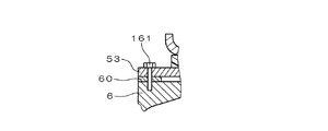
図3は、整流装置5の負極側放熱板53をフレーム6にネジを用いて固定した部分的な断面構造を示す図である。図3に示す構造では、負極側放熱板53とフレーム6との間に断熱部60を介在させた状態で、ステンレスで形成されたネジ161を用いて負極側放熱板53をフレーム6に固定している。ステンレスのネジ161を用いることにより、ネジ161を通してフレーム6から負極側放熱板53に熱が伝わりにくくすることができる。この場合に、ネジ161を介して負極側放熱板53をフレーム6に電気的に接続することができるが、断熱部60として導電体のステンレスを用いると、負極側放熱板53とフレーム6との間の電気抵抗をさらに低減することができる。
FIG. 3 is a diagram showing a partial cross-sectional structure in which the negative-side
図4は、導電体の断熱部60の他の例を示す図である。図4(A)に示すように中央に貫通孔を有する円柱状の断熱部60を金属材料で形成した場合に、図4(B)に示すように中空構造にすることにより、断熱効果を持たせることができる。なお、この金属材料を、ステンレス等の熱が伝わりにくい材質とすることにより、さらに断熱効果を上げることができる。なお、中央の貫通孔は図3に示したネジ161を貫通させるためのものである。使用箇所によってはネジ161を貫通させる必要がないため、どの部分に使用するかによって貫通孔を省略したり、円柱形状を変更するようにしてもよい。
FIG. 4 is a diagram illustrating another example of the
図5は、断熱部60を空隙とした場合の負極側放熱板53とフレーム6との電気的接続の例を示す部分的な断面図である。図5に示す構造では、断熱部60が空隙により形成されており、負極側放熱板53とフレーム6との間の電気的接続が導線162で行われている。導線162の両端にはワッシャ163が形成されており、これらをネジ164で負極側放熱板53とフレーム6のそれぞれに締め付け固定している。なお、導線162の固定は、溶接や半田付けで行うようにしてもよい。
FIG. 5 is a partial cross-sectional view showing an example of electrical connection between the negative-side
このように、本実施形態の車両用交流発電機1では、低損失素子としてのMOSトランジスタを用いることにより整流装置5自体の発熱量を下げることができ、しかも整流装置5とフレーム6との間に断熱部60を配置することによりフレーム6から伝わる熱を遮断することができるため、整流装置5の冷却性を向上させることができる。また、車両用交流発電機1の固定子2で発生した熱をフレーム6に伝達することができるため、車両用交流発電機1全体の冷却性悪化を防止することができる。
As described above, in the
なお、本発明は上記実施形態に限定されるものではなく、本発明の要旨の範囲内において種々の変形実施が可能である。例えば、上述した実施形態では、負極側放熱板53がフレーム6側に配置された整流装置5について説明したが、正極側放熱板52がフレーム6側に配置された整流装置についても本発明を適用することができる。この場合には、絶縁体としてのセラミックス、樹脂、ガラスを断熱部60として用いることにより、整流装置の正極側放熱板52とフレーム6との間の電気的絶縁の確保を同時に行うことが可能となる。また、この場合には、負極側放熱板53とフレーム6との電気的接続は、フレーム6から延びるスタットボルト65(図1)を介して行われるが、このスタットボルト65は熱が伝わりにくいステンレス等で形成することが望ましい。また、MOSトランジスタが1枚のパワー基板に配置された整流装置についても、本発明を適用することができるのは言うまでもない。
In addition, this invention is not limited to the said embodiment, A various deformation | transformation implementation is possible within the range of the summary of this invention. For example, in the above-described embodiment, the rectifying
また、上述した実施形態では、整流装置5を低損失素子としてのMOSトランジスタ5a〜5fを用いて構成したが、他の低損失素子、例えば低損失ダイオードを用いて整流装置を構成するようにしてもよい。
In the above-described embodiment, the
また、上述した実施形態では、発電機能を有する車両用交流発電機1について説明したが、発電機と電動機の機能を有する車両用回転電機に本発明を適用するようにしてもよい。この場合には、制御装置12の制御によって整流装置5をインバータ動作させて固定子巻線23に三相交流電圧を印加し、回転子3を回転させればよい。
In the above-described embodiment, the
また、上述した実施形態では、アルミニウムより熱伝導率が小さい部材の一例としてステンレスを用いたが、他の部材を用いるようにしてもよい。 In the above-described embodiment, stainless steel is used as an example of a member having a lower thermal conductivity than aluminum, but other members may be used.
1 車両用交流発電機
2 固定子
3 回転子
4 ブラシ装置
5 整流装置
6 フレーム
7 リヤカバー
8 プーリ
12 制御装置
51 端子台
52 正極側放熱板
53 負極側放熱板
60 断熱部
161、164 ネジ
DESCRIPTION OF
Claims (13)
前記整流装置と前記フレームとの間に断熱部を配置することを特徴とする車両用回転電機。 A rotor, a stator disposed opposite to the rotor, a frame made of aluminum that supports the rotor and the stator, and a low-loss element that is fixed to the outer end surface of the frame as a rectifying element In a rotating electrical machine for a vehicle provided with a rectifying device,
A rotating electrical machine for a vehicle, wherein a heat insulating portion is disposed between the rectifying device and the frame.
前記低損失素子は、低損失ダイオードであることを特徴とする車両用回転電機。 In claim 1,
The vehicular rotating electrical machine characterized in that the low-loss element is a low-loss diode.
前記低損失素子は、MOSトランジスタであることを特徴とする車両用回転電機。 In claim 1,
The vehicular rotating electrical machine, wherein the low-loss element is a MOS transistor.
前記断熱部は、アルミニウムより熱伝導率が小さい部材により形成されていることを特徴とする車両用回転電機。 In any one of Claims 1-3,
The rotary electric machine for vehicles, wherein the heat insulating portion is formed of a member having a lower thermal conductivity than aluminum.
前記断熱部は、ステンレスにより形成されていることを特徴とする車両用回転電機。 In any one of Claims 1-4,
The rotating electrical machine for a vehicle, wherein the heat insulating portion is made of stainless steel.
前記断熱部は、セラミックスにより形成されていることを特徴とする車両用回転電機。 In any one of Claims 1-4,
The rotating electrical machine for a vehicle, wherein the heat insulating portion is made of ceramics.
前記断熱部は、樹脂により形成されていることを特徴とする車両用回転電機。 In any one of Claims 1-4,
The vehicular rotating electrical machine, wherein the heat insulating portion is made of resin.
前記断熱部は、ガラスにより形成されていることを特徴とする車両用回転電機。 In any one of Claims 1-4,
The vehicular rotating electrical machine, wherein the heat insulating portion is made of glass.
前記断熱部は、空隙により形成されていることを特徴とする車両用回転電機。 In any one of Claims 1-4,
The rotating electrical machine for a vehicle, wherein the heat insulating portion is formed by a gap.
前記整流装置は、アルミニウムより熱伝導率が小さい部材で形成されたネジを用いて前記フレームに固定されていることを特徴とする車両用回転電機。 In any one of Claims 1-3,
The rotating electrical machine for a vehicle according to claim 1, wherein the rectifier is fixed to the frame using a screw formed of a member having a lower thermal conductivity than aluminum.
前記整流装置は、正極側整流素子が接合された正極側放熱板と、負極側整流素子が接合された負極側放熱板を備え、
前記負極側放熱板が前記断熱部を挟んで前記フレームと対向配置され、
前記断熱部が導電体により形成されており、前記断熱部を通して前記負極側放熱板と前記フレームとの間を電気的に接続することを特徴とする車両用回転電機。 In any one of Claims 1-3,
The rectifier includes a positive-side heat radiating plate to which a positive-side rectifying element is joined, and a negative-side heat radiating plate to which a negative-side rectifying element is joined,
The negative-side heat radiating plate is disposed opposite to the frame with the heat insulating portion interposed therebetween;
The rotating electrical machine for a vehicle, wherein the heat insulating portion is formed of a conductor, and the negative-side heat radiating plate and the frame are electrically connected through the heat insulating portion.
前記断熱部は、アルミニウムより熱伝導率が小さい部材により形成されていることを特徴とする車両用回転電機。 In claim 11,
The rotary electric machine for vehicles, wherein the heat insulating portion is formed of a member having a lower thermal conductivity than aluminum.
前記断熱部は、中空構造の導電体であることを特徴とする車両用回転電機。 In claim 11,
The rotating electrical machine for a vehicle, wherein the heat insulating portion is a hollow conductor.
Priority Applications (3)
| Application Number | Priority Date | Filing Date | Title |
|---|---|---|---|
| JP2008174051A JP4650528B2 (en) | 2008-07-03 | 2008-07-03 | Rotating electric machine for vehicles |
| US12/458,020 US8106547B2 (en) | 2008-07-03 | 2009-06-29 | Rotary electric machine for vehicles |
| EP09008563.0A EP2141786B2 (en) | 2008-07-03 | 2009-06-30 | Rotary electric machine for vehicles |
Applications Claiming Priority (1)
| Application Number | Priority Date | Filing Date | Title |
|---|---|---|---|
| JP2008174051A JP4650528B2 (en) | 2008-07-03 | 2008-07-03 | Rotating electric machine for vehicles |
Publications (2)
| Publication Number | Publication Date |
|---|---|
| JP2010016965A true JP2010016965A (en) | 2010-01-21 |
| JP4650528B2 JP4650528B2 (en) | 2011-03-16 |
Family
ID=41259652
Family Applications (1)
| Application Number | Title | Priority Date | Filing Date |
|---|---|---|---|
| JP2008174051A Expired - Fee Related JP4650528B2 (en) | 2008-07-03 | 2008-07-03 | Rotating electric machine for vehicles |
Country Status (3)
| Country | Link |
|---|---|
| US (1) | US8106547B2 (en) |
| EP (1) | EP2141786B2 (en) |
| JP (1) | JP4650528B2 (en) |
Cited By (5)
| Publication number | Priority date | Publication date | Assignee | Title |
|---|---|---|---|---|
| JP2013146120A (en) * | 2012-01-13 | 2013-07-25 | Denso Corp | Rotary electric machine for vehicle |
| JP2013236417A (en) * | 2012-05-07 | 2013-11-21 | Mitsubishi Electric Corp | Rotary electric machine |
| JP2015061451A (en) * | 2013-09-19 | 2015-03-30 | 株式会社デンソー | Rotary electric machine |
| WO2016017164A1 (en) * | 2014-08-01 | 2016-02-04 | パナソニックIpマネジメント株式会社 | Thermal insulation structure for electronic device, motor provided with said thermal insulation structure, and method for forming thermal insulation member for electronic device |
| JP2017055660A (en) * | 2016-12-25 | 2017-03-16 | 株式会社デンソー | Rotary electric machine |
Families Citing this family (6)
| Publication number | Priority date | Publication date | Assignee | Title |
|---|---|---|---|---|
| US8339000B2 (en) * | 2010-01-21 | 2012-12-25 | Remy Technologies, Llc | Electric machine with isolated ground electronics |
| FR3010591B1 (en) * | 2013-09-09 | 2017-07-28 | Valeo Equip Electr Moteur | COMBINATION OF A POWER BLOCK AND A FILTER BLOCK FOR A ROTATING ELECTRIC MACHINE FOR A MOTOR VEHICLE |
| US10298750B2 (en) * | 2013-11-21 | 2019-05-21 | Vodafone Ip Licensing Limited | Telecommunication networks for content delivery and lawful interception, content filtering and further content services using a SAVI platform |
| JP6402646B2 (en) * | 2015-02-19 | 2018-10-10 | 株式会社豊田自動織機 | Electric supercharger |
| US10784756B2 (en) * | 2017-02-02 | 2020-09-22 | Borgwarner Inc. | Electric machine with press-fit electronics package |
| FR3068185B1 (en) * | 2017-06-26 | 2019-12-13 | Valeo Equipements Electriques Moteur | MECHANICAL ASSEMBLY WITH ELECTRICAL INSULATION BETWEEN A ROTATING ELECTRIC MACHINE AND ITS ELECTRONIC PART |
Citations (13)
| Publication number | Priority date | Publication date | Assignee | Title |
|---|---|---|---|---|
| JPS6416164U (en) * | 1987-07-20 | 1989-01-26 | ||
| JPH0374163A (en) * | 1989-05-31 | 1991-03-28 | Nippondenso Co Ltd | Ac generator |
| JPH0678504A (en) * | 1992-08-25 | 1994-03-18 | Hitachi Ltd | Ac generator for vehicle |
| JPH06318657A (en) * | 1993-04-30 | 1994-11-15 | Mitsubishi Electric Corp | Semiconductor cooling device |
| JPH08331818A (en) * | 1995-06-02 | 1996-12-13 | Nippondenso Co Ltd | Ac generator |
| JPH099522A (en) * | 1995-06-23 | 1997-01-10 | Nippondenso Co Ltd | Vehicle ac generator and schottky barrier diode |
| JPH09157440A (en) * | 1995-12-13 | 1997-06-17 | Mitsubishi Electric Corp | Resin composition, resin-molded motor sealed with the same, resin sealing type semiconductor device and curing of the same |
| JPH10331281A (en) * | 1997-05-30 | 1998-12-15 | Sankyo Kogyo:Kk | External facing type heat-insulating structure for roof floor of building for cold reserving and execution method thereof |
| JP2004147486A (en) * | 2002-08-30 | 2004-05-20 | Denso Corp | Automotive ac generator |
| JP2004208467A (en) * | 2002-12-26 | 2004-07-22 | Denso Corp | Inverter to be mounted on polyphase ac rotary electric machine |
| JP2006504386A (en) * | 2002-10-28 | 2006-02-02 | ヴァレオ エキプマン エレクトリク モトゥール | A device for cooling power electronics integrated in the rear of an alternator or alternator / starter |
| JP2007288848A (en) * | 2006-04-13 | 2007-11-01 | Hitachi Ltd | Stator of rotating electric machine, its manufacturing method and ac generator |
| JP2008108950A (en) * | 2006-10-26 | 2008-05-08 | Matsushita Electric Ind Co Ltd | Linear motion device, and electronic component mounting device |
Family Cites Families (9)
| Publication number | Priority date | Publication date | Assignee | Title |
|---|---|---|---|---|
| JP3514319B2 (en) * | 1993-07-26 | 2004-03-31 | 株式会社デンソー | Rotating electric machine |
| FR2768870B1 (en) | 1997-09-25 | 2003-09-26 | Denso Corp | ALTERNATOR FOR A MOTOR VEHICLE |
| JP3430016B2 (en) * | 1998-06-05 | 2003-07-28 | 三菱電機株式会社 | AC generator for vehicles |
| DE19828518A1 (en) * | 1998-06-26 | 1999-12-30 | Bosch Gmbh Robert | Rectifier modular unit on a three-phase alternator |
| US6327128B1 (en) * | 1998-10-07 | 2001-12-04 | Electro-Dyn Electronics Corporation | Automotive bridge rectifier assembly with thermal protection |
| JP3944357B2 (en) | 2001-02-08 | 2007-07-11 | 三菱電機株式会社 | AC generator for vehicles |
| FR2869739B1 (en) | 2005-05-09 | 2009-06-26 | Valeo Equip Electr Moteur | ALTERNATOR, IN PARTICULAR FOR MOTOR VEHICLE |
| JP2008174051A (en) | 2007-01-17 | 2008-07-31 | Toyota Motor Corp | Air conditioner for vehicle and controlling method for it |
| FR2919770B1 (en) | 2007-08-01 | 2009-10-09 | Valeo Equip Electr Moteur | CURRENT RECTIFIER DEVICE FOR ROTATING ELECTRIC MACHINE AND ROTATING ELECTRIC MACHINE COMPRISING SUCH A DEVICE |
-
2008
- 2008-07-03 JP JP2008174051A patent/JP4650528B2/en not_active Expired - Fee Related
-
2009
- 2009-06-29 US US12/458,020 patent/US8106547B2/en not_active Expired - Fee Related
- 2009-06-30 EP EP09008563.0A patent/EP2141786B2/en not_active Not-in-force
Patent Citations (13)
| Publication number | Priority date | Publication date | Assignee | Title |
|---|---|---|---|---|
| JPS6416164U (en) * | 1987-07-20 | 1989-01-26 | ||
| JPH0374163A (en) * | 1989-05-31 | 1991-03-28 | Nippondenso Co Ltd | Ac generator |
| JPH0678504A (en) * | 1992-08-25 | 1994-03-18 | Hitachi Ltd | Ac generator for vehicle |
| JPH06318657A (en) * | 1993-04-30 | 1994-11-15 | Mitsubishi Electric Corp | Semiconductor cooling device |
| JPH08331818A (en) * | 1995-06-02 | 1996-12-13 | Nippondenso Co Ltd | Ac generator |
| JPH099522A (en) * | 1995-06-23 | 1997-01-10 | Nippondenso Co Ltd | Vehicle ac generator and schottky barrier diode |
| JPH09157440A (en) * | 1995-12-13 | 1997-06-17 | Mitsubishi Electric Corp | Resin composition, resin-molded motor sealed with the same, resin sealing type semiconductor device and curing of the same |
| JPH10331281A (en) * | 1997-05-30 | 1998-12-15 | Sankyo Kogyo:Kk | External facing type heat-insulating structure for roof floor of building for cold reserving and execution method thereof |
| JP2004147486A (en) * | 2002-08-30 | 2004-05-20 | Denso Corp | Automotive ac generator |
| JP2006504386A (en) * | 2002-10-28 | 2006-02-02 | ヴァレオ エキプマン エレクトリク モトゥール | A device for cooling power electronics integrated in the rear of an alternator or alternator / starter |
| JP2004208467A (en) * | 2002-12-26 | 2004-07-22 | Denso Corp | Inverter to be mounted on polyphase ac rotary electric machine |
| JP2007288848A (en) * | 2006-04-13 | 2007-11-01 | Hitachi Ltd | Stator of rotating electric machine, its manufacturing method and ac generator |
| JP2008108950A (en) * | 2006-10-26 | 2008-05-08 | Matsushita Electric Ind Co Ltd | Linear motion device, and electronic component mounting device |
Cited By (7)
| Publication number | Priority date | Publication date | Assignee | Title |
|---|---|---|---|---|
| JP2013146120A (en) * | 2012-01-13 | 2013-07-25 | Denso Corp | Rotary electric machine for vehicle |
| JP2013236417A (en) * | 2012-05-07 | 2013-11-21 | Mitsubishi Electric Corp | Rotary electric machine |
| JP2015061451A (en) * | 2013-09-19 | 2015-03-30 | 株式会社デンソー | Rotary electric machine |
| WO2016017164A1 (en) * | 2014-08-01 | 2016-02-04 | パナソニックIpマネジメント株式会社 | Thermal insulation structure for electronic device, motor provided with said thermal insulation structure, and method for forming thermal insulation member for electronic device |
| JPWO2016017164A1 (en) * | 2014-08-01 | 2017-05-18 | パナソニックIpマネジメント株式会社 | Heat insulation structure of electronic device, motor equipped with the heat insulation structure, and method for forming heat insulation member of electronic device |
| US10418875B2 (en) | 2014-08-01 | 2019-09-17 | Panasonic Intellectual Property Management Co., Ltd. | Thermal insulation structure for electronic device, motor provided with said thermal insulation structure, and method for forming thermal insulation member for electronic device |
| JP2017055660A (en) * | 2016-12-25 | 2017-03-16 | 株式会社デンソー | Rotary electric machine |
Also Published As
| Publication number | Publication date |
|---|---|
| EP2141786B8 (en) | 2015-05-27 |
| US8106547B2 (en) | 2012-01-31 |
| US20100001595A1 (en) | 2010-01-07 |
| EP2141786A1 (en) | 2010-01-06 |
| EP2141786B1 (en) | 2015-03-18 |
| EP2141786B2 (en) | 2018-05-02 |
| JP4650528B2 (en) | 2011-03-16 |
Similar Documents
| Publication | Publication Date | Title |
|---|---|---|
| JP4650528B2 (en) | Rotating electric machine for vehicles | |
| JP4754009B2 (en) | Rotating electric machine for vehicles | |
| JP3622350B2 (en) | Rotating electric machine | |
| EP1768236A1 (en) | Rotating electric machine integral with control device | |
| JP2010514405A (en) | Device for rectifying the current of a rotating electrical machine and rotating electrical machine having such a device | |
| US20160020679A1 (en) | Inverter-integrated motor | |
| JP2000253625A (en) | Ac generator for vehicle | |
| JP4081444B2 (en) | Alternators, especially automotive alternators | |
| JP2002165429A (en) | Alternating-current generator for vehicle | |
| JP2009060711A (en) | Vehicle alternator and rectifier | |
| US10432069B2 (en) | Controller-integrated rotary electric machine | |
| JP4692439B2 (en) | AC generator for vehicles | |
| JP2010239727A (en) | Ac generator for vehicle and generator motor device for vehicle | |
| JP5211914B2 (en) | Rotating electric machine for vehicles | |
| JP5955435B1 (en) | Belt-driven controller integrated AC motor generator | |
| JP4360024B2 (en) | Vehicle alternator | |
| JP2002142424A (en) | Alternator for vehicle | |
| JP4186838B2 (en) | Vehicle generator | |
| JP2002136016A (en) | Brushless ac generator | |
| JP5083665B2 (en) | Rotating electric machine for vehicles | |
| JP2007166900A (en) | Power unit for vehicle | |
| JP6149395B2 (en) | Rotating electric machine for vehicles | |
| JP2019161772A (en) | Rotary electric machine | |
| JP2015154638A (en) | Ac power generator for vehicles | |
| JP4487739B2 (en) | Vehicle alternator |
Legal Events
| Date | Code | Title | Description |
|---|---|---|---|
| A621 | Written request for application examination |
Free format text: JAPANESE INTERMEDIATE CODE: A621 Effective date: 20091126 |
|
| A131 | Notification of reasons for refusal |
Free format text: JAPANESE INTERMEDIATE CODE: A131 Effective date: 20100420 |
|
| A521 | Request for written amendment filed |
Free format text: JAPANESE INTERMEDIATE CODE: A523 Effective date: 20100615 |
|
| TRDD | Decision of grant or rejection written | ||
| A01 | Written decision to grant a patent or to grant a registration (utility model) |
Free format text: JAPANESE INTERMEDIATE CODE: A01 Effective date: 20101116 |
|
| A01 | Written decision to grant a patent or to grant a registration (utility model) |
Free format text: JAPANESE INTERMEDIATE CODE: A01 |
|
| A61 | First payment of annual fees (during grant procedure) |
Free format text: JAPANESE INTERMEDIATE CODE: A61 Effective date: 20101129 |
|
| R151 | Written notification of patent or utility model registration |
Ref document number: 4650528 Country of ref document: JP Free format text: JAPANESE INTERMEDIATE CODE: R151 |
|
| FPAY | Renewal fee payment (event date is renewal date of database) |
Free format text: PAYMENT UNTIL: 20131224 Year of fee payment: 3 |
|
| R250 | Receipt of annual fees |
Free format text: JAPANESE INTERMEDIATE CODE: R250 |
|
| R250 | Receipt of annual fees |
Free format text: JAPANESE INTERMEDIATE CODE: R250 |
|
| R250 | Receipt of annual fees |
Free format text: JAPANESE INTERMEDIATE CODE: R250 |
|
| R250 | Receipt of annual fees |
Free format text: JAPANESE INTERMEDIATE CODE: R250 |
|
| R250 | Receipt of annual fees |
Free format text: JAPANESE INTERMEDIATE CODE: R250 |
|
| R250 | Receipt of annual fees |
Free format text: JAPANESE INTERMEDIATE CODE: R250 |
|
| LAPS | Cancellation because of no payment of annual fees |