JP2010016556A - Button recognition unit, and button recognition method - Google Patents
Button recognition unit, and button recognition method Download PDFInfo
- Publication number
- JP2010016556A JP2010016556A JP2008173716A JP2008173716A JP2010016556A JP 2010016556 A JP2010016556 A JP 2010016556A JP 2008173716 A JP2008173716 A JP 2008173716A JP 2008173716 A JP2008173716 A JP 2008173716A JP 2010016556 A JP2010016556 A JP 2010016556A
- Authority
- JP
- Japan
- Prior art keywords
- button
- image
- illumination
- illumination image
- color
- Prior art date
- Legal status (The legal status is an assumption and is not a legal conclusion. Google has not performed a legal analysis and makes no representation as to the accuracy of the status listed.)
- Granted
Links
Images


Abstract
Description
本発明は、ボタン認識装置およびボタン認識方法に係り、特に、ボタンの構成情報を取得し、表裏を判別するボタン認識装置およびボタン認識方法に関する。 The present invention relates to a button recognition device and a button recognition method, and more particularly, to a button recognition device and a button recognition method that acquire configuration information of a button and discriminate between the front and the back.
従来より、自動ボタン縫い付け装置によってボタンを縫製物に縫い付けるにあたり、ボタンの表裏を判別するボタン認識装置が用いられている。 2. Description of the Related Art Conventionally, when a button is sewn to a sewing product by an automatic button sewing device, a button recognition device that distinguishes the front and back of the button has been used.
例えば、特許文献1には、ボタンの表裏を検知するためのボタン検知装置を備えた自動ボタン縫着装置が記載されている。このボタン検知装置は、ボタンつまみ足が上昇する際に、このボタンつまみ足によって保持されたボタンの上面に係合可能な位置に進退自在に配置され、ボタンの上面における縁部と中央部に係合可能なボタン検知手段と、このボタン検知手段の上下変位によってボタンの表裏を判別する判別手段とを有している。
For example,
この自動ボタン検知装置は、例えば、ボタン検知手段として、ボタン有無検知レバーおよびボタン表裏検知レバーを備えている。このような自動ボタン検知装置は、ボタン供給アームによってボタンつまみ足にボタンが供給された後、ボタンつまみ足が上昇する際に、ボタンの縁部によってボタン有無検知レバーが押し上げられたか否かにより、ボタンつまみ足におけるボタンの有無を検知するようになっている。また、自動ボタン検知装置は、ボタンの表面における中央部は窪んでおり、裏面における中央部は平面状であるというボタンの形状を利用して、ボタンつまみ足が上昇する際に、ボタンの中央部によってボタン表裏検知レバーが押し上げられたか否かにより、ボタンの表裏を判別するようになっている。 The automatic button detection device includes, for example, a button presence / absence detection lever and a button front / back detection lever as button detection means. Such an automatic button detection device is based on whether or not the button presence / absence detection lever is pushed up by the edge of the button when the button knob foot is raised after the button is supplied to the button knob foot by the button supply arm. The presence or absence of a button on the button knob foot is detected. In addition, the automatic button detection device uses a button shape in which the center part on the front surface of the button is recessed and the center part on the back surface is flat. The button front / back is discriminated based on whether or not the button front / back detection lever is pushed up.
また、特許文献2には、ボタン収納部および移動経路に所定の振動を発生させることにより、ボタン収納部に収納されたボタンを、ボタンの表裏選別後にボタン排出口から順次排出させるボタン供給部を備えたボタン供給装置が記載されており、このボタン供給装置は、移動経路の途中においてボタン選別機構を備えている。そして、このボタン選別機構においては、通常のボタンは、表面が窪んでおり裏面が平面状であるという形状を利用して、裏面が下側を向いているボタンは通過させるが、表面が下側を向いているボタンは、ボタン収納部における下方に落下させるようになっている。これにより、ボタン供給装置は、ボタンの表裏を判別し、表面が上側を向いているボタンのみをボタン排出口から順次排出するようになっている。 Patent Document 2 discloses a button supply unit that sequentially discharges the buttons stored in the button storage unit from the button discharge port after selecting the front and back of the button by generating predetermined vibrations in the button storage unit and the movement path. The button supply apparatus provided is described, This button supply apparatus is provided with the button selection mechanism in the middle of a movement path | route. And in this button selection mechanism, the normal button uses the shape that the front surface is recessed and the back surface is flat, and the button with the back surface facing downward is allowed to pass, but the front surface is on the lower side. The button which faces is adapted to drop downward in the button storage part. Thereby, the button supply device discriminates the front and back of the button, and sequentially discharges only the button whose surface faces upward from the button discharge port.
さらに、特許文献3には、ミシンに供給するボタンの上面を撮像して前方画像を取得する撮像手段を備えたボタンの縫着方向設定装置が記載されている。このボタンの縫着方向設定装置は、撮像手段により取得された前方画像と、ボタンについて予め記録された規格画像とに基づいて、ボタンを平面形状における所定の角度に傾けて配置して、ミシンに供給するようになっている。
Further,
また、特許文献3にも記載があるように、従来のボタン供給装置は、ボタンの糸通し孔に係止される係止ピンを有するボタン搬送部が設けられ、このボタン搬送部は、係止ピン上に載置されたボタンの上面からボタンを回転させながら係止ピン上に押し当ててボタンの糸通し孔に係止ピンを係止させることにより、ボタンを平面形状における所定の角度に傾けた状態で保持して、ミシンに供給するようになっている。
Further, as described in
しかし、前述の特許文献1に記載の自動ボタン検知装置および特許文献2に記載のボタン供給装置によれば、ボタンの表裏の判別を、ボタンの表面における中央部が窪み、裏面が平面状であるというボタン形状を利用して行うため、例えば、表裏の判別を形状ではなく表面に形成された刻印や画像等によってのみ判別可能なボタンについては、表裏を判別することができなかった。このため、前述の従来の自動ボタン検知装置およびボタン供給装置は、例えば、表裏の面形状が同じような多種多様なボタンの表裏判別に対応することができないという問題を有していた。
However, according to the automatic button detection device described in
さらに、引用文献3に記載のボタンの縫着方向設定装置によれば、ボタンの表面に形成された刻印や画像等によっても、ボタンの表裏を判別することが可能であるが、例えば、ボタンが光を反射する材料によって形成されている場合、ボタンの色彩や模様によっては、取得した前方画像において背景画像とボタン画像とを区別することが困難なことがあった。さらには、前述のボタンの縫着方向設定装置によれば、ボタンが透明または半透明の材料によって構成されている場合には、撮像手段によってボタンについて予め記録された規格画像と比較するために十分な前方画像を取得することができない場合があった。このため、このボタンの縫着方向設定装置は、例えば反射性の材料や透明、半透明の材料によって形成されているような多種多様なボタンの判別に対応することができないという問題を有していた。
Further, according to the button sewing direction setting device described in the cited
また、従来のボタン供給装置は、ボタンを係止ピンに持させる際に、製造精度の悪いボタンを排除することができなかった。例えば、糸通し孔の形成位置の精度が悪いボタンがボタン搬送部上に載置された場合、係止ピンが糸通し孔に係止されないまま回転装置によってボタンが係止ピン上に押し当てられてしまい、係止ピンが折れてしまうおそれがあるという問題を有していた。 Moreover, the conventional button supply apparatus cannot exclude a button with poor manufacturing accuracy when the button is held by the locking pin. For example, when a button with poor accuracy of the threading hole formation position is placed on the button transport unit, the button is pressed onto the locking pin by the rotating device without the locking pin being locked to the threading hole. Thus, there is a problem that the locking pin may be broken.
本発明はこれらの点に鑑みてなされたものであり、多種多様なボタンの構成情報を取得して、ボタンの表裏の判別精度の向上を図ることができるとともに、ミシンにより仕上がりよく縫製物にボタンを縫い付けることが可能なボタン認識装置およびボタン認識方法を提供することを目的とする。 The present invention has been made in view of these points, and can acquire various types of button configuration information to improve the accuracy of discriminating the front and back of the button, and the button can be applied to the sewing product with a good finish by the sewing machine. It is an object of the present invention to provide a button recognition device and a button recognition method capable of sewing a button.
前記目的を達成するため、請求項1に記載の発明に係るボタン認識装置の特徴は、ボタンの前面に対して垂直に照射光を照射する同軸落射照明装置と、前記ボタンの後面側に配置され、前記ボタンの後面から照射光を照射する透過照明装置と、前記ボタンの前面に対して斜方から照射光を照射する斜方照明装置と、前記同軸落射照明装置によって照射光が照射された状態での前記ボタンの前面の前方照明画像、前記斜方照明装置によって照射光が照射された状態での前記ボタンの前面の斜方照明画像および前記透過照明装置によって照射光が照射された状態での前記ボタンの前面の透過照明画像をそれぞれ撮像する撮像装置と、前記前方照明画像、前記斜方照明画像、および前記透過照明画像を用いて前記ボタンの構成情報を取得し、前記各照明画像、前記構成情報および予め記録された前記ボタンの規格画像を用いて前記ボタンの表裏を判別する画像処理装置とを備えた点にある。 In order to achieve the above object, the button recognition device according to the first aspect of the present invention is characterized in that a coaxial epi-illumination device that irradiates irradiation light perpendicularly to the front surface of the button and a rear surface side of the button. A state where irradiation light is irradiated by the transmission illumination device that irradiates irradiation light from the rear surface of the button, an oblique illumination device that irradiates irradiation light from the oblique direction to the front surface of the button, and the coaxial incident illumination device The front illumination image of the front surface of the button, the oblique illumination image of the front surface of the button in the state irradiated with the oblique illumination device, and the irradiation light irradiated with the transmission illumination device The configuration information of the button is acquired using an imaging device that respectively captures a transmission illumination image of the front surface of the button, the front illumination image, the oblique illumination image, and the transmission illumination image. Bright image, in that an image processing apparatus for discriminating the front and back of the button by using the configuration information and pre-recorded standard image of the button.
ここで、ボタンの構成情報とは、ボタンの外形・凹凸形状・外径・中心位置・平面形状における角度、およびボタンにおける糸通し孔の位置および径・中心位置等の撮像対象となるボタンを構成する諸要素の情報をいう。 Here, the button configuration information includes the button to be imaged such as the button's external shape, uneven shape, outer diameter, center position, plane shape, and threading hole position, diameter, center position, etc. This refers to information on various elements.
この請求項1に記載の発明によれば、前方照明画像のみならず、透過照明画像や斜方照明画像を用いることにより、ボタンの構成情報を精度よく取得することができる。すなわち、ボタン認識装置は、斜方照明装置によってボタンを照射した状態で撮像装置によってボタンの前面を撮像することにより、ボタンの前面の凹凸形状についての構成情報を取得することができる。また、ボタン認識装置は、透過照明装置によってボタンを照射した状態で撮像装置によってボタンの前面を撮像することにより、不透明体のボタンにおける糸通し孔の形成位置等について、高精度の構成情報を取得することができる。 According to the first aspect of the present invention, not only the front illumination image but also the transmitted illumination image and the oblique illumination image can be used to accurately obtain the button configuration information. That is, the button recognizing device can acquire configuration information about the concavo-convex shape of the front surface of the button by imaging the front surface of the button with the imaging device in a state where the button is illuminated by the oblique illumination device. In addition, the button recognition device captures the front surface of the button with the imaging device in a state where the button is irradiated with the transmissive illumination device, thereby acquiring high-accuracy configuration information about the threading hole formation position in the button of the opaque body. can do.
請求項2に記載の発明に係るボタン認識装置の特徴は、請求項1に記載のボタンの認識装置において、前記画像処理装置が、前記前方照明画像を用いて前記ボタンの前面の色彩を判別するとともに、前記前方照明画像および前記透過照明画像を用いて前記ボタンの透光度を判別し、判別した前記ボタンの色彩および透光度に応じて前記各照明装置の照明条件を調整する点にある。
The button recognition device according to claim 2 is characterized in that, in the button recognition device according to
この請求項2に記載の発明によれば、ボタンの前面の色彩情報を取得し、ボタンの透光度によってボタンを分類し、ボタンの色彩および透光度に応じて各照明装置における照射条件を設定することができる。これにより、より鮮明なボタンの各照明画像を取得することができるので、多種多様のボタンについて、より高精度の情報を取得することができる。 According to the second aspect of the present invention, the color information of the front surface of the button is acquired, the button is classified according to the light transmittance of the button, and the irradiation condition in each lighting device is determined according to the color and the light transmittance of the button. Can be set. Thereby, since each illumination image of a clearer button can be acquired, more highly accurate information can be acquired about a wide variety of buttons.
請求項3に記載の発明に係るボタン認識装置の特徴は、請求項2に記載のボタンの認識装置において、前記画像処理装置により判別されたボタンの色彩に応じて、前記ボタンに対する前記斜方照明装置の位置を調整することにより、前記斜方照明装置から前記ボタンの前面に照射される前記照射光の角度を調整する位置調整装置を備えた点にある。 According to a third aspect of the present invention, there is provided a button recognition apparatus according to the second aspect, wherein the oblique illumination for the button is performed according to the color of the button determined by the image processing apparatus. By adjusting the position of the device, a position adjusting device is provided that adjusts the angle of the irradiation light emitted from the oblique illumination device to the front surface of the button.
この請求項3に記載の発明によれば、ボタンの色彩に応じて、位置調整装置によってボタンに対する斜方照明装置の位置を調整することにより、斜方照明装置からボタンの前面に照射される照射光の角度を調整することができる。これにより、斜方照明装置によって、より鮮明にボタンの前面の凹凸形状を映し出すことができるので、多種多様なボタンについてより高精度の構成情報を取得することができ、表裏判別の精度もより向上させることができる。 According to the third aspect of the invention, the irradiation of the front surface of the button from the oblique illumination device is performed by adjusting the position of the oblique illumination device with respect to the button by the position adjusting device according to the color of the button. The angle of light can be adjusted. As a result, the oblique illumination device can more clearly project the concavo-convex shape of the front of the button, so it is possible to obtain more accurate configuration information for a wide variety of buttons, and the accuracy of front / back discrimination is further improved. Can be made.
請求項4に記載の発明に係るボタン認識装置の特徴は、請求項2または請求項3に記載のボタン認識装置において、前記透過照明装置として、前記ボタンの背景色を表示する表示装置を用い、前記表示装置は、前記画像処理装置により判別された前記ボタンの色彩に応じて、照射する照射光の色彩を設定する点にある。
The button recognition device according to
この請求項4に記載の発明によれば、透過照明装置としての表示装置は照射光の色彩を変更することができるので、ボタンの色彩に応じて表示装置からの照射光の色彩を変更することにより、前方照明画像におけるボタン部分と背景部分とをより容易に分離することができるような背景色を設定することが可能となる。これにより、同軸落射照明装置によって、より鮮明にボタンの前面を映し出すことができるので、多種多様なボタンについてより高精度の構成情報を取得することができ、表裏判別の精度もより向上させることができる。 According to the fourth aspect of the present invention, since the display device as the transmission illumination device can change the color of the irradiation light, the color of the irradiation light from the display device can be changed according to the color of the button. Thus, it is possible to set a background color that can more easily separate the button portion and the background portion in the front illumination image. As a result, the front surface of the button can be projected more clearly by the coaxial epi-illumination device, so that more accurate configuration information can be obtained for a wide variety of buttons, and the accuracy of front / back discrimination can be further improved. it can.
請求項5に記載の発明に係るボタン認識装置の特徴は、請求項2乃至請求項4のいずれか1項に記載のボタン認識装置において、前記透過照明装置として、前記ボタンの背景パターンを表示する表示装置を用い、前記表示装置は、前記画像処理装置により判別された前記ボタンの透光度に応じて、前記背景パターンを設定する点にある。
The button recognition device according to
この請求項5に記載の発明によれば、透過照明装置としての表示装置は表示する背景パターンを変更することができるので、ボタンの透過度に応じて表示装置により表示される背景パターンを変更することにより、前方照明画像におけるボタン部分と背景部分とを容易に分離可能な背景パターンを設定することが可能となる。これにより、同軸落射照明装置によって、より鮮明にボタンの前面を映し出すことができるので、多種多様なボタンについてより高精度の構成情報を取得することができ、表裏判別の精度をより向上させることができる。 According to the fifth aspect of the present invention, since the display device as the transmissive illumination device can change the background pattern to be displayed, the background pattern displayed by the display device is changed according to the transparency of the button. Thus, it is possible to set a background pattern that can easily separate the button portion and the background portion in the front illumination image. As a result, the front surface of the button can be projected more clearly by the coaxial epi-illumination device, so that more accurate configuration information can be obtained for a wide variety of buttons, and the accuracy of front / back discrimination can be further improved. it can.
請求項6に記載の発明に係るボタン認識方法の特徴は、ボタンの前面に対して垂直に照射光を照射して、撮像装置により前記ボタンの前面の前方照明画像を撮像する前方照明画像取得工程と、前記ボタンの後面から照射光を照射して、前記撮像装置により前記ボタンの前面の透過照明画像を撮像する透過照明画像取得工程と、前記ボタンの前面に対して斜方から照射光を照射して、前記撮像装置により前記ボタンの前面の斜方照明画像を撮像する斜方照明画像取得工程と、前記前方照明画像、前記斜方照明画像および前記透過照明画像を用いて前記ボタンの構成情報を取得し、前記各照明画像、前記構成情報および予め記録されたボタンの規格画像を用いて前記ボタンの表裏を判別する画像処理工程とを有する点にある。 A feature of the button recognition method according to the invention of claim 6 is that a front illumination image acquisition step of irradiating irradiation light perpendicularly to the front surface of the button and capturing a front illumination image of the front surface of the button by an imaging device. A transmission illumination image acquisition step of irradiating irradiation light from the rear surface of the button and capturing a transmission illumination image of the front surface of the button by the imaging device; and irradiating irradiation light from an oblique direction to the front surface of the button Then, an oblique illumination image acquisition step of capturing an oblique illumination image of the front surface of the button by the imaging device, and the configuration information of the button using the front illumination image, the oblique illumination image, and the transmitted illumination image And an image processing step of discriminating the front and back of the button using each illumination image, the configuration information, and a standard image of the button recorded in advance.
この請求項6に記載の発明によれば、前方照明画像のみならず、透過照明画像や斜方照明画像を用いることにより、ボタンの構成情報を精度よく取得することができる。すなわち、本発明に係るボタン認識方法は、ボタンの前面に対して斜方から照射光を照射した状態でボタンの前面を撮像することにより、ボタンの前面の凹凸形状についての構成情報を取得することができる。また、ボタン認識方法は、ボタンの後面から照射光を照射した状態でボタンの前面を撮像することにより、不透明体のボタンにおける糸通し孔の形成位置等について、高精度の構成情報を取得することができる。 According to the sixth aspect of the present invention, not only the front illumination image but also the transmitted illumination image and the oblique illumination image can be used to obtain the button configuration information with high accuracy. That is, the button recognition method according to the present invention obtains configuration information about the concavo-convex shape of the front surface of the button by imaging the front surface of the button in a state where irradiation light is obliquely applied to the front surface of the button. Can do. In addition, the button recognition method acquires high-accuracy configuration information on the threading hole formation position, etc., in the button of the opaque body by imaging the front surface of the button with irradiation light from the rear surface of the button. Can do.
請求項7に記載の発明に係るボタン認識方法の特徴は、請求項6に記載のボタン認識方法において、前記前方照明画像を用いて前記ボタンの前面の色彩情報を取得し、前記前方画像および前記透過照明画像を用いて、前記ボタンの透過度に応じて前記ボタンを分類し、前記ボタンの色彩および透光度に応じて前記各照明装置の照明条件を調整する点にある。
A feature of the button recognition method according to
この請求項7に記載の発明によれば、ボタンの前面の色彩情報を取得し、ボタンの透光度によってボタンを分類し、ボタンの色彩および透光度に応じて各照明画像取得工程における照射条件を設定することができる。これにより、より鮮明なボタンの各照明画像を取得することができるので、多種多様のボタンについて、より高精度の情報を取得することができる。 According to the seventh aspect of the invention, the color information on the front surface of the button is acquired, the buttons are classified according to the translucency of the button, and the illumination in each illumination image acquisition process is performed according to the color and translucency of the button. Conditions can be set. Thereby, since each illumination image of a clearer button can be acquired, more highly accurate information can be acquired about a wide variety of buttons.
請求項8に記載の発明に係るボタン認識方法の特徴は、請求項7に記載の発明に係るボタン認識方法において、前記ボタンの色彩に応じて、前記斜方照明画像取得工程において前記ボタンに対して照射光を照射する位置を調整することにより、前記ボタンの前面に照射される照射光の角度を調整する位置調整工程を有する点にある。 The button recognition method according to an eighth aspect of the present invention is characterized in that, in the button recognition method according to the seventh aspect of the present invention, in the oblique illumination image acquisition step, the button is recognized according to the color of the button. By adjusting the position where the irradiation light is irradiated, there is a position adjustment step of adjusting the angle of the irradiation light irradiated on the front surface of the button.
この請求項8に記載の発明によれば、ボタンの色彩に応じて、斜方照明画像取得工程においてボタンに照射光を照射する照射位置を調整することにより、ボタンの前面に斜方から照射される照射光の照射角度を調整することができる。これにより、斜方照明画像取得工程において、ボタンの前面の凹凸形状がより鮮明に映し出された斜方照明画像を取得することができるので、多種多様なボタンについてより高精度の構成情報を取得することができ、表裏判別の精度もより向上させることができる。 According to the eighth aspect of the present invention, the front surface of the button is irradiated obliquely by adjusting the irradiation position for irradiating the button with the irradiation light in the oblique illumination image acquisition step according to the color of the button. The irradiation angle of the irradiation light can be adjusted. As a result, in the oblique illumination image acquisition step, an oblique illumination image in which the uneven shape on the front surface of the button is more clearly projected can be acquired, so that more accurate configuration information is acquired for a wide variety of buttons. And the accuracy of front / back discrimination can be further improved.
請求項9に記載の発明に係るボタン認識方法の特徴は、請求項7または請求項8に記載のボタン認識方法において、前記前方照明画像取得工程において、前記ボタンの色彩に応じて、前記ボタンの背景の色彩を設定する点にある。
The button recognition method according to claim 9 is characterized in that, in the button recognition method according to
この請求項9に記載の発明によれば、ボタンの色彩に応じてボタンの背景の色彩を設定することができるので、前方照明画像においてボタン部分と背景部分とをより容易に分離することができるような背景の色彩を設定することが可能となる。これにより、前方照明画像取得工程において、より鮮明な前方照明画像を取得することができるので、多種多様なボタンについてより高精度の構成情報を取得することができ、表裏判別の精度もより向上させることができる。 According to the ninth aspect of the present invention, since the background color of the button can be set according to the color of the button, the button portion and the background portion can be more easily separated in the front illumination image. It is possible to set a background color like this. As a result, a clearer front illumination image can be acquired in the front illumination image acquisition step, so that more accurate configuration information can be acquired for a wide variety of buttons, and the accuracy of front / back discrimination is further improved. be able to.
請求項10に記載の発明に係るボタン認識方法の特徴は、請求項7乃至請求項9のいずれか1項に記載のボタン認識方法において、前記前方照明画像取得工程で、前記ボタンの透光度に応じて、前記ボタンの背景パターンを設定する点にある。
The button recognition method according to
この請求項10に記載の発明によれば、ボタンの透過度に応じてボタンの背景パターンを設定することができるので、前方照明画像においてボタン部分と背景部分とを分離可能な背景パターンを設定することが可能となる。これにより、前方照明画像取得工程において、より鮮明な前方照明画像を取得することができるので、多種多様なボタンについてより高精度の構成情報を取得することができ、表裏判別の精度をより向上させることができる。
According to the invention described in
請求項11に記載の発明に係るボタン認識方法の特徴は、請求項10に記載のボタン認識方法において、前記ボタンの透光度により前記ボタンが透明な材料により構成されていると分類された場合には、前記ボタンの背景パターンを周期的な模様に設定し、前記ボタンを透過することにより前記ボタン部分の背景パターンが歪んで視認されることを利用して、前記前方照明画像における背景部分とボタン部分とを分離し、前記ボタンの外形輪郭線を取得する点にある。
The button recognition method according to claim 11 is characterized in that, in the button recognition method according to
この請求項11に記載の発明によれば、透明の材料からなるボタンについて前方照明画像を取得する際に、背景パターンを周期的な模様とすることにより、背景部分とボタン部分とをより明確に分離して、ボタンの外形輪郭線を抽出することができる。 According to the eleventh aspect of the present invention, when a front illumination image is acquired for a button made of a transparent material, the background portion and the button portion are more clearly defined by making the background pattern a periodic pattern. The button outline contour can be extracted separately.
以上述べたように、本発明に係るボタン認識装置によれば、多種多様のボタンについて、高精度の構成情報に基づいてボタンの表裏を判別することができ、表裏の判別精度を向上させることができるとともに、前記構成情報を用いて不良品のボタンを除去したり、ボタンを平面形状における所定の角度に傾けて配置させることができ、ミシンによって仕上がりよく縫製物にボタンを縫い付けることができる。 As described above, according to the button recognition device of the present invention, it is possible to determine the front and back of the button based on high-precision configuration information for a wide variety of buttons, and to improve the determination accuracy of the front and back. In addition, it is possible to remove defective buttons by using the configuration information, or to arrange the buttons by tilting them at a predetermined angle in a planar shape, and to sew the buttons to the sewing product with a good finish.
また、本発明に係るボタン認識装置によれば、不透明体のボタンにおける糸通し孔の形成位置について高精度の構成情報を取得することにより、製造精度が悪いボタンを判別することができるので、ミシンの縫い針が糸通し孔を通過せずにボタンに接触することによる縫い針折れ等のトラブルの発生を防止することができる。 Further, according to the button recognition device of the present invention, it is possible to discriminate a button with poor manufacturing accuracy by acquiring highly accurate configuration information about the formation position of the threading hole in the opaque button. Occurrence of troubles such as breakage of the sewing needle due to contact of the sewing needle with the button without passing through the threading hole can be prevented.
また、本発明に係るボタン認識方法によれば、多種多様のボタンについて、高精度の構成情報に基づいてボタンの表裏を判別することができ、表裏の判別精度を向上させることができるとともに、前記構成情報を用いて不良品のボタンを排除したり、ボタンを平面形状における所定の角度に傾けて配置させることができ、ミシンによって仕上がりよく縫製物にボタンを縫い付けることができる。 In addition, according to the button recognition method according to the present invention, for a wide variety of buttons, the front and back of the button can be determined based on highly accurate configuration information, the front and back determination accuracy can be improved, The configuration information can be used to eliminate defective buttons, or the buttons can be tilted at a predetermined angle in the planar shape, and the buttons can be sewn to the sewing product with a good finish.
また、本発明に係るボタン認識方法によれば、不透明体のボタンにおける糸通し孔の形成位置について高精度の構成情報を取得することにより、製造精度が不良なボタンを判別することができるので、ミシンの縫い針が糸通し孔を通過せずにボタンに接触することによる縫い針折れ等のトラブルの発生を防止することができる。 In addition, according to the button recognition method according to the present invention, it is possible to determine a button with poor manufacturing accuracy by acquiring highly accurate configuration information about the formation position of the threading hole in the button of the opaque body. Occurrence of troubles such as broken stitches caused by the sewing needle of the sewing machine contacting the button without passing through the threading hole can be prevented.
以下、本発明に係るボタン認識装置の一実施形態を図1から図13を参照して説明する。 Hereinafter, an embodiment of a button recognition apparatus according to the present invention will be described with reference to FIGS.
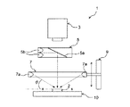
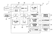
図1は、本実施形態に係るボタン認識装置を示す概略側面断面図であり、図2は、図1のボタン認識装置の構成を示すブロック図である。 FIG. 1 is a schematic side sectional view showing a button recognition device according to the present embodiment, and FIG. 2 is a block diagram showing a configuration of the button recognition device of FIG.
図1および図2に示すように、本実施形態に係るボタン認識装置1は、ボタン2の前面(上面)の画像を取得する撮像装置としてのカメラ3がボタン2の前方(図1において上方)に配置されており、このカメラ3は、ボタン2の上面の画像を取得するようになっている。
As shown in FIGS. 1 and 2, in the
ボタン2の上方であって、ボタン2とカメラ3との間には、ボタン2の上面に対して垂直に照射光を照射するための同軸落射照明装置5が配設されている。同軸落射照明装置5は、ボタン2の上方に配置されたハーフミラー5aと、カメラ3によって取得されるボタン2の上面の画像の撮像領域から外れた位置に配置され、ハーフミラー5aにおけるボタン2に対向している下面に対して照射光を照射する光源5bとを有している。ハーフミラー5aは、光源5bから照射された照射光を下面において反射して、ボタン2の上面に対して垂直に照射するように、光源5bおよびボタン2に対して所定の角度をもって配置されている。そして、同軸落射照明装置5は、カメラ3に対向する上面側からボタン2に対して照射光を照射できるようになっている。
A coaxial epi-
そして、カメラ3は、同軸落射照明によってボタン2の上面に照射光を照射した状態でボタン2の上面を撮像することにより前方照明画像を取得するようになっており、これにより、ボタン2の上面における色彩や、文字・図形等の模様等を映し出すことができるようになっている。
The
ボタン2の上方であって、ボタン2と同軸落射照明との間には、ボタン2の上面に対して斜方から照射光を照射する斜方照明装置7が配設されている。斜方照明装置7は、カメラ3による画像の撮像領域から外れた位置に配置され、ボタン2の上面に対して斜方から照射光を照射する一対の光源7aとを有している。両光源7aは、ボタン2に対して右側上方および左側上方の対称の位置からそれぞれ同一の照射角度によってボタン2の上面を照射する位置に配置されている。
Above the button 2 and between the button 2 and the coaxial epi-illumination, an
また、ボタン認識装置1は、ボタン2に対する斜方照明装置7の位置を調整することにより、斜方照明装置7からボタン2の上面に照射される照射光の照射角度を調整する位置調整装置9を備えている。本実施形態においては、位置調整装置9は、ボタン2の上面に対する斜方照明装置7の高さ位置を調整することにより、ボタン2の上面に照射される照射光の照射角度を調整することができるようになっている。
Further, the
そして、カメラ3は、斜方照明装置7によってボタン2の上面に照射光を照射した状態でボタン2の上面を撮像して斜方照明画像を取得するようになっており、これにより、ボタン2の上面に形成された刻印等の凹凸形状を映し出すことができるようになっている。このカメラ3による撮像の前に、位置調整装置9は、同軸落射照明装置5によって取得された前方照明画像を用いて判別されたボタン2の色彩に応じて、ボタン2に対する斜方照明装置7の高さ位置を調整することにより、斜方照明装置7の両光源7aからボタン2の上面に照射される照射光の照射角度を調整するようになっている。
The
ボタン2の下面側には、ボタン2の下面から照射光を照射する透過照明装置として液晶表示パネル10が設けられており、液晶表示パネル10は、ボタン2の下面から照射光を照射する照明装置として機能するほか、ボタン2を載置する載置台として機能するようになっている。さらに、液晶表示パネル10による表示は、前方照明画像や斜方照明画像を取得する際の背景として機能するようになっている。
On the lower surface side of the button 2, a liquid
そして、カメラ3は、液晶表示パネル10によってボタン2の下方から照射光を照射した状態でボタン2の上面を撮像して透過照明画像を取得することができるようになっており、これにより、ボタン2のシルエットを映し出すようになっている。
The
また、ボタン認識装置1は、カメラ3によって取得された前方照明画像、斜方照明画像および透過照明画像について各種の処理を行う画像処理装置12を有している。画像処理装置12は、前方照明画像を用いてボタン2の上面の色彩を判別し、前方照明画像と透過照明画像とを用いてボタン2の透光度に応じてボタン2が不透明体、半透明体、透明体のいずれで形成されているかを分類し、さらには、前方照明画像、斜方照明画像および透過照明画像を用いてボタン2の構成を計測して構成情報を取得し、構成情報に基づいてボタン2の表裏を判別するようになっている。
The
画像処理装置12は、画像処理装置12の各部を制御するCPU15と、前方照明画像、斜方照明画像および透過照明画像を記録する画像メモリ16と、各照明画像と照合するためのボタン2の上面についての規格画像等が予め記録されている第1記録メモリ17と、CPU15が画像処理を行うための画像データの仮の格納場所であるワークメモリ18とを有している。カメラ3は、アナログ・デジタルコンバータ(A/Dコンバータ)19を介して画像メモリ16に接続されており、カメラ3が取得した前方照明画像、斜方照明画像および透過照明画像の各画像データは、A/Dコンバータ19によりデジタル化された後、画像メモリ16において記録されるようになっている。
The
また、画像処理装置12は、カメラ3の制御を行うカメラ制御部21と、同軸落射照明装置5の制御を行う同軸落射照明制御部22と、斜方照明装置7の制御を行う斜方照明制御部23と、位置調整装置9の制御を行う位置調整制御部25、および液晶表示パネル10の制御を行うパネル制御部26とを有している。
In addition, the
さらに、画像処理装置12は、各照明装置5、7、10によって各照明画像を取得するために各照明装置5、7、10および位置調整装置9を制御する処理、前方照明画像を用いて色彩を判別する処理、前方照明画像および透過照明画像を用いて透光度によってボタン2を分類する処理、および各照明画像を用いてボタン2の構成情報を取得し、ボタン2の表裏を判別する処理を行うための画像処理プログラムを有している。画像処理プログラムは、第2記録メモリ28に記録されている。
Further, the
そして、画像処理装置12は、CPU15によって、第2記録メモリ28から画像処理プログラムを読み出して、各制御部21、22、23、25、26に制御情報を出力し、各制御部21、22、23、25、26によって、各照明装置5、7、10によりボタン2に照射光を照射し、位置調整装置9により斜方照明装置7の高さ位置を調整して、カメラ3によりボタン2を撮像するようになっている。また、画像処理装置12は、CPU15によって、前方照明画像を用いてボタン2の色彩を判別し、色彩情報を取得するとともに、ボタン2の構成を計測してボタン2の構成情報を取得して、ボタン2の表裏を判別するようになっている。
Then, the
このとき、画像処理装置12は、前方照明画像の前方照明画像データに基づいて判別したボタン2の色彩に応じて、液晶表示パネル10の表示によるボタン2の背景色を設定するようになっている。また、画像処理装置12は、前方照明画像および透過照明画像の各画像データを用いてボタン2の透光度によって分類したボタン2の種類に応じて、液晶表示パネル10により表示されるボタン2の背景パターンを設定するようになっている。さらに、画像処理装置12は、前方照明画像および透過照明画像の各画像データに基づいて判別したボタン2の色彩に応じて、位置調整装置9によって調整する斜方照明装置7の高さ位置を決定するようになっている。
At this time, the
そして、CPU15は、インターフェース(I/F)20を介してミシンの各部を制御するミシン制御部30に接続されており、画像処理装置12のCPU15は、ボタン2の構成情報および表裏の判別結果をI/F20を介してミシン制御部30に出力するようになっている。ミシン制御部30は、ボタン2の表面が上方を向いているという判別結果を入力した場合には、入力したボタン2の構成情報における平面形状のボタン2の傾きの構成情報に基づいて、平面状におけるボタン2の配置角度を補正し、ボタン2を縫製物に縫い付けるようになっている。一方、ミシン制御部30は、ボタン2の裏面が上方を向いているという判別結果を入力した場合には、ボタン2を除去し、撮像対象となる次のボタン2を液晶表示パネル10の上にセットするようになっている。
The
次に、本実施形態にかかるボタン認識装置1を用いたボタン認識方法につき、図3から図13を参照して説明する。
Next, a button recognition method using the
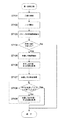
図3は、本実施形態に係るボタン認識方法の各工程を示すフローチャートである。 FIG. 3 is a flowchart showing each step of the button recognition method according to the present embodiment.
図3に示すように、まず、ボタン認識装置1の画像処理装置12におけるCPU15は、透過照明画像を取得する透過照明画像取得工程を行う(ST1)。
As shown in FIG. 3, first, the
この透過照明画像取得工程において、まず、画像処理装置12のCPU15は、第2記録メモリ28から画像処理プログラムを読み出し、パネル制御部26を介して液晶表示パネル10を制御し、液晶表示パネル10によって、所定の色彩、光量により所定の背景パターンを表示する。この透過照明画像取得工程の段階では、画像処理装置12は、撮像対象であるボタン2の透光度や色彩等を認識していないので、液晶表示パネル10においてまず白色無地パターンを表示する。その後、CPU15は、液晶表示パネル10によって液晶表示パネル10の上に載置されたボタン2の下方からボタン2に白色の照射光を照射した状態で、カメラ3によってボタン2の上面を撮像することにより、透過照明画像を取得する。そして、CPU15は、透過照明画像の透過照明画像データをA/Dコンバータ19によってデジタル化した後、画像メモリ16に記録する。
In this transmitted illumination image acquisition step, first, the
このとき、ボタン2が不透明な材料で構成されている場合には、カメラ3は、明瞭なシルエットの透過照明画像を取得することができる。また、ボタン2が透明な材料で構成されている場合には、液晶表示パネル10からの照射光はボタン2を透過してしまうので、カメラ3により取得された透過照明画像は、全体的に白くなってしまい、カメラ3は、ボタンの明瞭なシルエットが映し出された透過照明画像を取得することができない。さらに、ボタン2が半透明な材料で構成されている場合には、カメラ3によって取得した透過照明画像は、コントラストが低かったり、輝度がまだらでボタン2の形状がおぼろげとなり、カメラ3は、ボタンの明瞭なシルエットが映し出された透過照明画像を取得することができない。
At this time, when the button 2 is made of an opaque material, the
続いて、CPU15は、透過照明画像取得工程の後、透過照明画像データを用いて、ボタン2の外径・中心位置、糸通し孔の数・外径・中心位置・形成位置等のボタン2の構成を計測し、構成情報を取得する第1計測工程を行う(ST2)。
Subsequently, after the transmitted illumination image acquisition step, the
この第1計測工程においては、図4に示すように、まず、画像処理装置12のCPU15は、透過照明画像データについて、背景部分とボタン部分とに分けるためのしきい値を設定し、二値化処理を行う(ST101)。透過照明画像データについて二値化処理を行った二値化画像データにおいては、例えば、液晶表示パネル10からの照射光がカメラ3に到達する部分が0となり、到達しない部分が1となる。ここで、第1計測工程において用いるしきい値としては、透過照明画像データにおいて背景部分とボタン部分とを分けるときに、透光度がほとんど0%である不透明な材料で構成されているボタン2のみを分類できるように、不透明な材料により構成されているボタン2においては外形輪郭線の抽出が困難となる程度の値に調整することが望ましい。そして、CPU15は、二値化処理を行った透過照明画像の二値化画像データをワークメモリ18に出力する。
In this first measurement step, as shown in FIG. 4, first, the
続いて、CPU15は、前記二値化画像データのノイズ処理を行う(ST102)。ノイズ処理としては、0に隣接する1を0にするオープニング処理と、1に隣接する0を1にするクロージング処理を行うことにより、細かいノイズ成分の除去、線の途切れの埋め、および穴埋めを行う。
Subsequently, the
次に、CPU15は、前記二値化画像データを用いてボタン2の外形輪郭線を抽出する処理を行う(ST103)。外形輪郭線を抽出する処理としては、画像において連結した画素の集合に、番号(ラベル)を付加することにより画素の集合を分類するラベリング処理を行い、各画素の集合の境界線を追跡することにより、ボタン2の外形輪郭線を抽出することができる。なお、ここでは、画像データが背景のみの場合、ラベル数を0としてラベルを付加するものとする。この場合、ボタン2が不透明な場合は、ラベルとして1が付加されるが、ボタン2が透明で背景のみで全く外形輪郭線が得られなかったり、断片的な画素の集合が取得されたりする場合は、ラベル数として0や2以上の番号が付されることになる。
Next, the
その後、CPU15は、外形輪郭線を抽出する工程において、ボタン2の外形輪郭線の抽出の処理で付加されたラベル数を判別することにより、外形輪郭線が正常に抽出できたか否かを判別する(ST104)。これにより、CPU15は、ボタン2の外形輪郭線が正常に抽出できないと判断した場合には(ST104においてNo)、撮像対象となっているボタン2が透明体または半透明体であると判断し、透過照明画像データを用いた第1計測工程を終了する。
Thereafter, in the step of extracting the outline contour, the
ここで、ST103の処理では、ボタン2が透明体であった場合、液晶表示パネル10からの照射光は、ボタン2を透過してカメラ3に到達してしまうので、透過照明画像取得工程においてカメラ3はボタン2のシルエットを映し出すことができない。このため、二値化処理(ST101)、ノイズ処理(ST102)が終了した段階において、透過照明画像データの二値化画像データは背景部分のみしか存在しないので、CPU15は、外形輪郭線を抽出する工程(ST103)において、ボタン2の外形輪郭線が正常に抽出できず、ラベル数が1となっているため、ボタン2が透明体であると判断、分類する(ST104においてNo)。
Here, in the process of ST103, if the button 2 is a transparent body, the irradiation light from the liquid
また、ボタン2が半透明体であった場合、ボタン2による液晶表示パネル10からの照射光の遮断が不十分であるので、透過照明画像取得工程においてカメラ3によって映し出される透過照明画像が低コントラストとなる場合がある。このような場合にも、二値化処理(ST101)、ノイズ処理(ST102)が終了した段階において、前述のボタン2が透明体の場合と同様に、ラベル数が1となっているため、ボタン2の外形輪郭線が正常に抽出できないと判断される(ST104においてNo)ことになる。
Further, when the button 2 is a semi-transparent body, the irradiation light from the liquid
また、ボタン2が半透明体であり、かつボタン2の厚みが均一でない場合には、ボタン2を透過する液晶表示パネル10の照射光の透光度が均一にならず、このため、カメラ3により取得された透過照明画像は濃度がまだらであったり、濃度の変化が緩やかとなる。このため、例えば、CPU15による二値化処理(ST101)やノイズ処理(ST102)が行われると、ボタン2の画像として断片的な複数の画素の集合が形成され、外形輪郭線抽出処理におけるラベリング処理(ST103)において、2以上のラベル数が付されることになり、CPU15は、ラベル数が2以上であることを判断することにより、撮像対象となっているボタン2は半透明な材料からなり、透過照明画像によっては十分にボタン2の外形輪郭線を抽出することができないと判断することができる(ST104においてNo)。なお、抽出したボタン2の外形輪郭線が円形かどうか、または急峻な外周縁上の点か否かを検出することにより、ボタン2が半透明体であることを判断しても良い。
Further, when the button 2 is a semi-transparent body and the thickness of the button 2 is not uniform, the transmissivity of the irradiation light of the liquid
そして、CPU15は、外形輪郭線を抽出する工程において、ボタン2の外形輪郭線を正常に抽出できたと判断した場合には(ST104においてYes)、糸通し孔の外形輪郭線を抽出する処理を行う(ST105)。この糸通し孔の外形輪郭線の抽出工程においては、透過照明画像の二値化画像データにおいて背景を排除した後、再度ラベリング処理を行い、検出したボタン部分の境界線を追跡することにより、糸通し孔の外形輪郭線を抽出する。
If the
次いで、CPU15は、前記二値化画像データを用いてボタン2の外径を検出し、ボタン2の中心位置を取得した後(ST106)、糸通し孔の外形輪郭線の抽出工程においてラベリング処理された二値化データを用いて、糸通し孔の数を取得する(ST107)。
Next, the
次に、CPU15は、ST107において検出された数の糸通し孔のすべてについて外径および中心位置を取得する工程を終了したか否かを判別する(ST108)。このとき、CPU15は、糸通し孔のすべてについて外径および中心位置を取得する工程を終了していないと判断した場合には(ST108においてNo)、前記二値化画像データを用いて糸通し孔の外径を検出し、糸通し孔の中心位置を取得して(ST109)、このボタン2の外径・中心位置、糸通し孔の数・外径・中心位置・形成位置に関する構成情報をインタフェース(I/F)20を介してミシン制御部30に出力する。また、この情報は表裏判別工程で利用するため、ワークメモリ18に保持しておく。その後、CPU15は、再度、ST108において検出された数のすべての糸通し孔の外径および中心位置を取得する工程を終了したか否かを判別する(ST108)。
Next, the
一方、CPU15は、すべての糸通し孔の外径および中心位置の取得が終了したと判断した場合には(ST108においてYes)、透過照明画像データを用いた第1計測工程を終了する。
On the other hand, if the
続いて、CPU15は、前方照明画像を取得する前方照明画像取得工程を行う(ST3)。 Then, CPU15 performs the front illumination image acquisition process which acquires a front illumination image (ST3).
この前方照明画像取得工程において、まず、画像処理装置12のCPU15は、画像プログラムに基づき、パネル制御部26を介して液晶表示パネル10を制御し、液晶表示パネル10によって、所定の色彩および光量によって所定の背景パターンを表示する。この前方照明画像取得工程の段階では、液晶表示パネル10を背景パネルとして使用するので、黒色無地のパターンの表示を行う。そして、CPU15は、同軸落射照明装置5によって液晶表示パネル10の上に載置されたボタン2の上方からボタン2に対して垂直に照射光を照射した状態で、カメラ3によってボタン2の上面を撮像することにより、カラーの前方照明画像を取得する。この前方照明画像取得工程においては、ボタン2の形状や上面に記載された文字、図形等の模様が映し出される。そして、CPU15は、前方照明画像の前方照明画像データをA/Dコンバータ19によってデジタル化した後、画像メモリ16に記録する。
In this front illumination image acquisition step, first, the
次に、CPU15は、前方照明画像データを用いて色彩情報を取得することにより色彩を判別する色彩判別工程を行う(ST4)。
Next, the
この色彩判別工程においては、図5に示すように、まず、前方照明画像データについて、再び、第1ボタン計測工程(ST2)のボタン2の外形輪郭線を抽出する工程(ST103)と同様の処理を行い、前方照明画像データにおけるボタン2の外形輪郭線を抽出する(ST201)。 In this color discrimination step, as shown in FIG. 5, first, the same process as the step (ST103) of extracting the outer contour of the button 2 in the first button measurement step (ST2) again for the front illumination image data. And the outline of the button 2 in the front illumination image data is extracted (ST201).
続いて、CPU15は、上述したST103における工程でのラベリング処理により付されたラベル数の値と前方照明画像データの外形輪郭線抽出の工程(ST201)でのラベリング処理により付されたラベル数とに基づいて、撮像対象となるボタン2が透明体か否かを判別する(ST202)。なお、この判断においては、ST103とST201の両工程でのラベリング処理によるラベル数がともに0である場合に、ボタン2が透明体であると判断する(ST202においてYes)。
Subsequently, the
このとき、CPU15は、ボタン2が透明体でないと判断した場合には(ST202においてNo)、ボタン2が不透明体または半透明体であると判断し、透過照明画像データおよび前方照明画像データを用いて、ボタン2の色彩情報を得るためのサンプリング領域を設定する(ST203)。次に、CPU15は、前記サンプリング領域における各画素について、RGB値の平均値をそれぞれ算出し(ST204)、さらに、前記サンプリング領域における各画素のRGB値を、色相、明度、彩度の色彩情報の表現に変換した後(ST205)、前記色相および前記明度の色彩情報をマンセル表色系に基づいて数値化して色情報を取得し、ワークメモリ18に出力、保持しておき(ST206)、色彩情報取得工程を終了する。ここで取得した色情報は、斜方照明装置の高さ位置調整工程(ST9)、表裏判別工程(ST13)で利用する。
At this time, if the
一方、CPU15は、撮像対象となるボタン2が透明体であると判断した場合には(ST202においてYes)、色彩情報を取得することができないので、色彩情報取得工程を終了する。
On the other hand, if the
次に、CPU15は、ボタン2が不透明体または半透明体で構成されていたため色彩情報取得工程(ST4)において色彩情報を取得することができたか否かを判別し(ST5)、取得できないと判断した場合には(ST5においてNo)、ボタン2が透明な材料で構成されているボタンであると分類し、透明な材料により構成されたボタン2の外径・中心位置、糸通し孔の数・外径・中心位置・形成位置等の構成を計測し構成情報を取得する第2計測工程を行う(ST6)。
Next, the
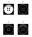
この第2計測工程においては、図6に示すように、まず、CPU15は、液晶表示パネル10において表示されるボタン2の背景パターンを設定する(ST301)。背景パターンとしては、例えば、図7(1)示す横縞模様や、図7(2)に示す斜め縞模様や、図7(3)に示す市松模様のような周期的な模様が用いられる。
In the second measurement step, as shown in FIG. 6, first, the
続いて、CPU15は、パネル制御部26を介して、液晶表示パネル10により背景パターンの設定工程(ST301)において設定された背景パターンを表示する(ST302)。
Subsequently, the
さらに、CPU15は、同軸落射照明制御部22を介して同軸落射照明装置5によりボタン2に照射光を照射しながら、カメラ制御部21を介してカメラ3により前方照明画像を撮像して前方照明画像データを取得する(ST303)。そして、CPU15は、この前方照明画像データを画像メモリ16に記録する。
Further, the
次に、CPU15は、第2計測工程(ST6)の前方照明画像を取得する工程(ST303)において取得した前方照明画像データを用いて、ボタン2の外形輪郭線を抽出する処理を行う(ST304)。
Next, the
ここで、液晶表示パネル10からの照射光は、透明体のボタン2を透過して空気中に出射する際に必ず屈折する。また、透明体のボタン2を透過した照射光は、ボタン2の形状によっては透視歪が発生し、ボタン2によって凸レンズの条件が成立すれば拡散され、凹レンズの条件が成立すれば集光することとなる。このため、取得した前方照明画像データ上において、背景部分は液晶表示パネル10によって表示された背景パターンがそのまま周期的なパターンによって撮像される。一方、ボタン部分は背景パターンの周期性が乱れることとなる。これにより、撮像されたパターンが周期的な部分と周期的ではない部分との境界線を追跡することにより、背景とボタン2とを分離し、ボタン2の外径輪郭線を抽出することができる。
Here, the irradiation light from the liquid
このボタン2の外径輪郭線の抽出工程は(ST304)、背景パターンの模様の周期情報はわかっているので、例えば、前方照明画像データについてフーリエ変換を行って周波数成分にし、背景部分の周波数成分のみを削除した後、逆フーリエ変換を行って、元の前方照明画像データに戻すことにより行う。これにより、図8に示すようなボタン部分のみの前方照明画像データを得る。そして、このようなボタン部分のみの前方照明画像データについて、背景部分とボタン部分との境界線を追跡して、図9に示すような二値化画像データを得て、ボタン2の外径輪郭線を抽出する。 In this step of extracting the outer diameter contour of the button 2 (ST304), since the period information of the pattern of the background pattern is known, for example, the front illumination image data is subjected to Fourier transform to obtain a frequency component, and the frequency component of the background portion. After deleting only, the inverse Fourier transform is performed to restore the original front illumination image data. Thereby, the front illumination image data of only the button part as shown in FIG. 8 is obtained. Then, with respect to the front illumination image data of only the button part, the boundary line between the background part and the button part is traced to obtain binary image data as shown in FIG. Extract lines.
そして、CPU15は、ボタン2の外径輪郭線の抽出工程(ST304)において、抽出したボタン2の外形輪郭線が円形かどうか、または急峻な外周縁上の点を有するか否かを検出することにより、正常に外形輪郭線を抽出することができたか否かを判別し(ST305)、正常に抽出することができないと判断した場合には(ST305においてNo)、第2計測工程(ST6)を終了する。
Then, the
一方、CPU15は、外形輪郭線を正常に抽出することができたと判断した場合には(ST305においてYes)、糸通し孔の輪郭線を抽出する処理を行う(ST306)。この糸通し孔の輪郭線の抽出工程においては、図8に示すST304において取得したボタン部分のみの前方照明画像データを用いて、ST305と同等の方法により糸通し孔の輪郭線を抽出することができる。また、ST305と同等の方法によって図9に示す二値化画像データを得た後、この二値化画像データを用いてST105と同等の方法により糸通し孔の輪郭線を抽出してもよい。
On the other hand, when
その後、CPU15は、前記二値化画像データを用いてボタン2の外径を検出し、ボタン2の中心位置を取得した後(ST307)、糸通し孔の輪郭線の抽出工程においてラベリング処理された二値化データを用いて、糸通し孔の数を取得する(ST308)。
After that, the
次に、CPU15は、ST308において検出された数の糸通し孔のすべてについて外径および中心位置を取得する工程を終了したか否かを判別する(ST309)。このとき、CPU15は、糸通し孔のすべてについて外径および中心位置を取得する工程を終了していないと判断した場合には(ST309においてNo)、前記二値化画像データを用いて糸通し孔の外径を検出し、糸通し孔の中心位置を取得し(ST310)、このボタン2の外径・中心位置、糸通し孔の数・外径・中心位置・形成位置に関する構成情報をインタフェース(I/F)20を介してミシン制御部30に出力する。また、この情報は表裏判別工程で利用するため、ワークメモリ18に保持しておく。その後、CPU15は、再度、ST308において検出された数の糸通し孔のすべてについて外径および中心位置を取得する工程を終了したか否かを判別する(ST309)。
Next,
一方、CPU15は、糸通し孔のすべてについての外径および中心位置の取得が終了したと判断した場合には(ST309においてYes)、第2計測工程を終了する。
On the other hand, when
一方、CPU15は、色彩情報取得工程(ST4)において色彩情報を取得することができできたと判断した場合には(ST5においてYes)、第1ボタン計測工程(ST2)において、ST104で肯定判断される(ST104においてYes)ことより、ボタン2の外形輪郭線を抽出できたか否かを判別する(ST7)。そして、ボタン2の外形輪郭線を抽出することができなかったと判断した場合には(ST7においてNo)、半透明の材料により構成されたボタン2の外径・中心位置、糸通し孔の数・外径・中心位置・形成位置等の構成を計測し構成情報を取得する第3計測工程を行う(ST8)。
On the other hand, if the
この第3計測工程においては、図10に示すように、まず、CPU15は、液晶表示パネル10において表示されるボタン2の背景パターンを設定する(ST401)。この背景パターンとしては、ST4の色彩判別工程において判別されたボタン2の色彩に対して、より背景分離が容易になるような背景色となるように設定する。例えば、第3計測工程においてカラー画像を用いて処理を行う場合には、ボタン2の色彩と補色の関係にある色彩を背景色として設定するとよい。また、第3計測工程においてカラー画像を濃淡画像にしてこの濃淡画像を用いて処理を行う場合には、背景部分とボタン部分の濃度差がより大きくなるような色彩を背景色として設定するとよい。さらには、白色または黒色をボタン2の色彩に応じて切り替えてもよい。
In the third measurement step, as shown in FIG. 10, first, the
続いて、CPU15は、パネル制御部26を介して液晶表示パネル10により背景パターンの設定工程(ST401)において設定された背景パターンを表示する(ST402)。そして、CPU15は、同軸落射照明制御部22を介して、同軸落射照明装置5によりボタン2に照射光を照射しながら、カメラ3部を介してカメラ3により前方照明画像を撮像して前方照明画像データを取得し(ST403)、この前方照明画像データを画像メモリ16に記録する。
Subsequently, the
次に、CPU15は、第3計測工程(ST8)の前方照明画像を取得する工程(ST403)において取得した前方照明画像データを用いて、ボタン2の外形輪郭線を抽出する処理を行う(ST404)。 Next, CPU15 performs the process which extracts the external outline of the button 2 using the front illumination image data acquired in the process (ST403) which acquires the front illumination image of a 3rd measurement process (ST8) (ST404). .
このボタン2の外形輪郭線を抽出する工程においては(ST404)、前方照明画像データをカラー画像のまま用いる場合には、背景色は、背景パターンの設定工程(ST401)において設定されたものであるためわかっているので、背景パターンの色彩情報をもとに、ボタン2と背景の領域を分割して、その境界線を追跡することによりボタン2の外形輪郭線を抽出することができる。また、前記前方照明画像のカラー画像を濃淡画像にして、この濃淡画像を用いてボタン2の外形輪郭線の抽出を行う場合、背景パターンの設定工程(ST401)において、予め背景部分とボタン部分との濃度差が大きくなるように設定されているため、背景部分とボタン部分とのコントラストが高い。このため、判別分析法などの動的なしきい値取得アルゴリズムを用いてしきい値を求め、前記前方照明画像の濃淡画像について二値化処理を行うことにより、透過照明画像データと同様の画像データを得ることができる。その後、ST103と同様に前記前方照明画像データについてラベリング処理を行い、背景とボタン2との境界線を追跡することにより、ボタン2の外形輪郭線を抽出する。 In the step of extracting the outline of the button 2 (ST404), when the front illumination image data is used as a color image, the background color is set in the background pattern setting step (ST401). Therefore, based on the color information of the background pattern, the outline of the button 2 can be extracted by dividing the button 2 and the background area and tracking the boundary line. Further, when the color image of the front illumination image is converted into a grayscale image, and the contour outline of the button 2 is extracted using the grayscale image, the background portion, the button portion, and the button portion are previously set in the background pattern setting step (ST401). Therefore, the contrast between the background portion and the button portion is high. Therefore, by obtaining a threshold value using a dynamic threshold value acquisition algorithm such as a discriminant analysis method and performing binarization processing on the gray image of the front illumination image, image data similar to the transmission illumination image data is obtained. Can be obtained. After that, as in ST103, the front illumination image data is labeled, and the outline of the button 2 is extracted by tracking the boundary line between the background and the button 2.
そして、CPU15は、ボタン2の外形輪郭線の抽出工程(ST404)において、抽出したボタン2の外形輪郭線が円形かどうか、または急峻な外周縁上の点を有するか否かを検出することにより、正常に外形輪郭線を抽出することができたか否かを判別し(ST405)、正常に抽出することができないと判断した場合には(ST405においてNo)、第3計測工程(ST8)を終了する。
Then, the
一方、CPU15は、外形輪郭線を正常に抽出することができたと判断した場合には(ST405においてYes)、糸通し孔の輪郭線を抽出する処理を行う(ST406)。この糸通し孔の輪郭線の抽出工程は、ST404のボタン2の外形輪郭線を抽出する工程と同等の方法を用いて、糸通し孔の輪郭線を抽出することができる。
On the other hand, when
その後、CPU15は、前記前方照明画像データを用いてボタン2の外径・中心位置を検出し(ST407)、前記前方照明画像データを用いて、糸通し孔の数を取得する(ST408)。
Thereafter, the
次に、CPU15は、ST408において検出された数の糸通し孔のすべてについて外径および中心位置を取得する工程を終了したか否かを判別し(ST409)、終了していないと判断した場合には(ST409においてNo)、前記前方照明画像データを用いて糸通し孔の外径を検出し、糸通し孔の中心位置を取得して(ST410)、このボタン2の外径・中心位置、糸通し孔の数・外径・中心位置・形成位置に関する構成情報をインタフェース(I/F)20を介してミシン制御部30に出力する。また、この情報は表裏判別工程で利用するため、ワークメモリ18に保持しておく。その後、CPU15は、再度、ST408において検出された数の糸通し孔のすべてについて外径および中心位置を取得する工程を終了したか否かを判別する(ST409)。
Next, the
一方、CPU15は、糸通し孔のすべてについて外径および中心位置の取得が終了したと判断した場合には(ST409においてYes)、第3計測工程を終了する。
On the other hand, when
そして、CPU15は、第2計測工程(ST6)が終了した場合、第3計測工程(ST8)が終了した場合、またはST2の第1ボタン計測工程においてボタン2の外形輪郭線を抽出できたと判断した場合には(ST7においてYes)、斜方照明装置7によってボタン2に対して照射光を照射する位置を調整することにより(ST9)、ボタン2の上面に照射される照射光の角度を調整する。
Then, the
斜方照明装置7の位置調整工程においては、図11に示すように、まずCPU15は、色彩判別工程(ST4)において判別されたボタン2の色彩情報に基づいて、ボタン2の上面における光の反射率を取得し(ST501)、演算した反射率から、ボタン2の上面の傾斜や刻印等の凹凸形状を撮像可能にするための斜方照明装置7から照射する照射光の照射角度(θ)および光量を取得する(ST502)。ここで、ボタン2の上面の色彩の明度が低く反射率が低いほど、θを大きく設定し(図1参照)、ボタン2の上面の色彩の明度が高く反射率が高いほど、換言すれば明るい色ほど、θを小さく設定するとともに光量を多く設定する。このような反射率とθおよび光量との関係は、予め実験により算出し、テーブルとして第1記録メモリ17に記録しておくこともできる。そして、CPU15は、演算したθによって斜方照明装置7からの照射光がボタン2の上面に照射されるように、斜方照明装置7の高さ位置を演算し(ST503)、設定した斜方照明装置7の高さ位置を位置調整制御部25に出力するとともに、光量を斜方照明制御部23に出力して(ST504)、位置調整工程を終了する。
In the position adjustment process of the
続いて、CPU15は、斜方照明装置7によってボタン2の上面を照射光により照射した状態で、カメラ3によりボタン2の上面を撮像して斜方照明画像を取得する処理を行う(ST10)。
Subsequently, the
この斜方照明画像取得工程においては、CPU15は、位置調整制御部25により入力した高さ位置に基づいて斜方照明装置7の高さ位置を調整するとともに、斜方照明制御部23により入力した光量に基づいて斜方照明装置7の光量を調整し、ボタン2の上方から前記高さ位置および光量により斜方照明装置7によって所定の角度をもってボタン2の上面に散乱光の照射光を照射する。そして、CPU15は、斜方照明装置7によってボタン2の上面に照射光を照射した状態で、カメラ制御部21を介してカメラ3によってボタン2の上面を撮像して斜方照明画像の暗視野画像を取得する。この斜方照明画像取得工程においては、特に、ボタン2の上面の凹凸形状が映し出される。
In this oblique illumination image acquisition step, the
その後、CPU15は、ST3、ST303、またはST403の前方照明画像取得工程において取得した前方照明画像と、ST10の斜方照明画像取得工程において取得した斜方照明画像とを合成する処理を行う(ST11)。
Thereafter, the
この画像合成工程において、CPU15は、例えば、図12(a)に示すよう撮像対象のボタン2について、ST10の斜方照明画像取得工程において撮像された図12(b)に示す斜方照明画像と、ST3、ST303、またはST403の前方照明画像取得工程において取得された図12(c)に示すような前方照明画像とを合成する。ここで、斜方照明画像取得工程(ST10)において取得される斜方照明画像の暗視野画像においては、撮影対象のボタン2が透明体の場合には、ボタン2の上面に記載された文字、図形等の模様は、ボタン2の上面において斜方照明装置7からの照射光が散乱して白く映し出される。しかし、ボタン2が不透明体の場合には、ボタン2の上面に記載された画像は映し出されず、ボタン2の上面の凹凸形状が映し出されることとなる。一方、前方照明画像においては、特に、ボタン2の上面の画像が映し出されている。これにより、CPU15は、斜方照明画像と前方照明画像とを合成して、図12(d)に示すようなボタン2の上面に記載された画像および凹凸形状が映し出された合成画像を生成する。
In this image composition step, for example, as shown in FIG. 12A, the
さらに、CPU15は、画像合成工程(ST11)における合成画像を用いて、ボタン2の上面に記載された文字等の模様や、凹凸形状により形成された文字等の模様を検出する処理を行う(ST12)。
Further, the
この画像検出工程においては、CPU15は、合成画像データについてラベリング処理を行い、ボタン2の上面の模様部分について模様の外形輪郭線を追跡し、模様の外形輪郭線を抽出する。続いて、CPU15は、模様のラベル毎に重心を求めて、模様の中心位置を検出し、この模様中心位置の情報を、各ボタン2のボタン2の外形、凹凸形状、外径および中心位置、さらには糸通し孔の位置、外径、および中心位置等の構成情報に付加する。これにより、ボタン2の表面に模様がある場合、ボタン2を縫製物に縫着する際に複数のボタン2において模様の向きが揃うように、ボタン2の平面形状における角度を調整することが可能となる。
In this image detection step, the
そして、CPU15は、ST1〜ST12において取得された撮像対象となるボタン2の透過照明画像、前方照明画像、および斜方照明画像を用いて判別および計測され、ワークメモリ18に保持していた色彩情報および構成情報を用いて、ボタン2の表裏を判別する(ST13)。
Then, the
この表裏判別工程においては、図13に示すように、まず、CPU15は、ワークメモリ18に保存されているボタン2の構成情報に基づいて、ボタン2の平面形状における角度およびボタン2の中心位置を取得する(ST601)。
In this front / back discrimination step, as shown in FIG. 13, first, the
ボタン2の平面形状における角度を取得する工程においては、1つのボタン2について2つの糸通し孔が形成されている場合には、2つの糸通し孔の中心位置を連結する直線の傾きによって、平面形状におけるボタン2の角度を取得する。1つのボタン2について3つの糸通し孔が正三角形の各頂点上に形成されている場合には、3つの糸通し孔のうちいずれか1つの糸通し孔の中心位置をとおり、かつ他の2つの糸通し孔を連結する直線に対して垂直な直線の傾きによって、平面形状におけるボタン2の角度を取得する。1つのボタン2について4つの糸通し孔が形成されている場合には、4つの糸通し孔のうちいずれか1つの糸通し孔を選択して、選択した糸通し孔に一番近接して形成された糸通し孔と選択した糸通し孔との中心位置を連結する直線を基準とする。さらに、選択されていない他の3つの糸通し孔についても一番近接して形成された糸通し孔と直線によって連結し、各直線の傾きを加味して平均を採用することにより、平面形状におけるボタン2の角度を取得する。 In the step of obtaining the angle in the planar shape of the button 2, when two threading holes are formed for one button 2, the plane is determined by the inclination of a straight line connecting the center positions of the two threading holes. Get the angle of the button 2 in the shape. When three threading holes are formed on each vertex of the equilateral triangle with respect to one button 2, it passes through the center position of any one of the three threading holes and the other 2 The angle of the button 2 in the planar shape is acquired by the inclination of the straight line perpendicular to the straight line connecting the two threading holes. When four threading holes are formed for one button 2, any one of the four threading holes is selected and formed closest to the selected threading hole. A straight line that connects the center positions of the threaded hole and the selected threading hole is used as a reference. Further, the other three threading holes that are not selected are connected to the threading holes formed closest to each other by a straight line, and an average is adopted in consideration of the inclination of each straight line. Get the angle of button 2.
ボタン2の中心位置の取得工程においては、ボタン2の外形輪郭線の重心をボタン2の中心位置とする。 In the step of acquiring the center position of the button 2, the center of gravity of the outline outline of the button 2 is set as the center position of the button 2.
続いて、CPU15は、ボタン2における糸通し孔の数を判別する(ST602)。
Subsequently, the
ここで、糸通し孔の数が2つの場合には、まず、撮像対象となるボタン2の合成画像と比較されるボタン2の規格画像を2方向に回転したか否かを判別し(ST603)、2方向に回転していないと判断した場合には(ST603においてNo)、合成画像と規格画像とのマッチングを行って相関値を求めた後(ST604)、規格画像を180°回転して(ST605)、再度、規格画像を2方向に回転したか否かを判別する(ST603)。このようにして、2方向分の合成画像と規格画像との相関値を求める。 Here, when the number of threading holes is two, first, it is determined whether or not the standard image of the button 2 to be compared with the composite image of the button 2 to be imaged is rotated in two directions (ST603). If it is determined that the image has not been rotated in two directions (No in ST603), the composite image and the standard image are matched to obtain a correlation value (ST604), and then the standard image is rotated 180 ° ( (ST605) It is determined again whether the standard image has been rotated in two directions (ST603). In this way, the correlation value between the composite image for two directions and the standard image is obtained.
糸通し孔の数が3つの場合には、まず、規格画像を3方向に回転したか否かを判別し(ST606)、3方向に回転していないと判断した場合には(ST606においてNo)、合成画像と規格画像とのマッチングを行って相関値を求めた後(ST607)、規格画像を120°回転して(ST608)、再度、規格画像を3方向に回転したか否かを判別する(ST606)。このようにして、3方向分の合成画像と規格画像との相関値を求める。 If the number of threading holes is three, it is first determined whether or not the standard image has been rotated in three directions (ST606). If it is determined that the standard image has not been rotated in three directions (No in ST606). After the correlation between the composite image and the standard image is obtained (ST607), the standard image is rotated by 120 ° (ST608), and it is determined again whether the standard image is rotated in three directions. (ST606). In this way, the correlation value between the composite image for three directions and the standard image is obtained.
糸通し孔の数が4つの場合には、まず、規格画像を4方向に回転したか否かを判別し(ST609)、4方向に回転していないと判断した場合には(ST609においてNo)、合成画像と規格画像とのマッチングを行って相関値を求めた後(ST610)、規格画像を90°回転して(ST611)、再度、規格画像を4方向に回転したか否かを判別する(ST609)。このようにして、4方向分の合成画像と規格画像との相関値を求める。 If the number of threading holes is four, first, it is determined whether or not the standard image has been rotated in four directions (ST609). If it is determined that the standard image has not been rotated in four directions (No in ST609). After the correlation between the composite image and the standard image is obtained (ST610), the standard image is rotated by 90 ° (ST611), and it is determined again whether the standard image is rotated in four directions. (ST609). In this way, correlation values between the composite image for four directions and the standard image are obtained.
さらに、CPU15は、各方向について、各相関値のうちの最大値を評価値に決定し(ST612)、ボタン2の表裏を判別するために予め設定されているしきい値と評価値とを比較して、相関値の方が大きいか否か判別する(ST613)。そして、規格画像としてボタン2の表面の画像データが登録されている場合、CPU15は、相関値の方がしきい値よりも大きいと判断した場合には(ST613においてYes)、撮像対象となっているボタン2は表面が上方に向いていると判断し(ST614)、相関値の方がしきい値よりも小さいと判断した場合には(ST613においてNo)、ボタン2は裏面が上方に向いていると判断する(ST615)。このとき、撮像対象となったボタン2が、例えば外周縁が欠けている等の不良品であって、相関値の方がしきい値よりも小さくなってしまった場合には、ボタン2は裏面が上方に向いていると判断されることとなる。
Further, for each direction,
CPU15は、撮像対象となっているボタン2の表裏を判別した後、表裏の判別結果、色彩情報および構成情報をI/F20を介してミシン制御部30に出力する(ST616)。
After determining the front and back of the button 2 to be imaged, the
ミシン制御部30は、入力したボタン2の表裏の判別結果に基づき、ボタン2の裏面が上方に向いているのであれば、そのボタン2を除去し、ボタン2の表面が上方に向いているのであれば、入力したボタン2の構成情報に基づいて糸通し孔の形成位置や糸通し孔の外径を確認する。そして、ミシン制御部30は、糸通し孔の形成位置がずれていたり、糸通し孔の外径が小さいと判断した場合には、そのようなボタン2も除去し、正常なボタン2であると判断した場合には、構成情報に基づきボタン2の平面形状における角度を調整して、縫製物に縫い付ける作業を行う。
The sewing
本実施形態によれば、前方照明画像のみならず、透過照明画像や斜方照明画像を用いることにより、ボタン2の外形・外径・中心位置・上面の凹凸形状、糸通し孔の数・外径・中心位置・形成位置等の構成情報を精度よく取得することができる。すなわち、ボタン認識装置1は、斜方照明装置7によってボタン2を照射した状態でカメラ3によってボタン2の上面を撮像することにより、ボタン2の上面の凹凸形状についての構成情報を取得することができる。また、ボタン認識装置1は、液晶表示パネル10によってボタン2を照射した状態でカメラ3によってボタン2の上面を撮像することにより、不透明体のボタン2における糸通し孔の形成位置等について、高精度の構成情報を取得することができる。
According to this embodiment, by using not only the front illumination image but also the transmitted illumination image and the oblique illumination image, the outer shape / outer diameter / center position / upper surface uneven shape of the button 2, the number of threading holes / outside Configuration information such as diameter, center position, and formation position can be obtained with high accuracy. That is, the
したがって、本実施形態に係るボタン認識装置1は、多種多様のボタン2について、高精度の構成情報に基づいてボタン2の表裏を判別することができ、表裏の判別精度を向上させることができるとともに、前記構成情報を用いて不良品のボタン2を除去したり、ボタン2を平面形状における所定の角度に向けて配置させることができ、ミシンによって仕上がりよく縫製物にボタン2を縫い付けることができる。
Therefore, the
また、ボタン認識装置1は、不透明体のボタン2における糸通し孔の形成位置について高精度の構成情報を取得することにより、製造精度が不良なボタン2を判別することができるので、ミシンの縫い針が糸通し孔を通過せずにボタン2に接触することによる縫い針折れ等のトラブルの発生を防止することができる。
Further, the
さらに、ボタン認識装置1は、ボタン2の上面の色彩情報を取得し、ボタン2の透光度によってボタン2を分類し、ボタン2の色彩及び透光度に応じて各照明装置5、7、10における照射条件を設定することができる。これにより、より鮮明なボタン2の各照明画像を取得することができるので、多種多様のボタン2について、より高精度の情報を取得することができる。
Further, the
さらにまた、ボタン2の色彩に応じて、位置調整装置9によってボタン2に対する斜方照明装置7の位置を調整することにより、斜方照明装置7からボタン2の上面に照射される照射光の角度を調整することができる。これにより、斜方照明装置7によって、より鮮明にボタン2の上面の凹凸形状を映し出すことができるので、多種多様なボタン2についてより高精度の構成情報を取得することができ、表裏判別の精度もより向上させることができる。
Furthermore, by adjusting the position of the
また、液晶表示パネル10は照射光の色彩を変更することができるので、ボタン2の色彩に応じて液晶表示パネル10からの照射光の色彩を変更することにより、前方照明画像においてボタン部分と背景部分とをより容易に分離することができるような背景色を設定することが可能となる。例えば、不透明の材料からなるボタン2については黒色の背景色に設定し、半透明の材料からなるボタン2について、ボタン2の色彩と補色関係の色彩を背景色に設定したり、前方照明画像においてボタン部分と背景部分とのコントラストがより高くなる色彩を背景色に設定することにより、背景部分とボタン部分とをより明確に分離して、ボタン2の外形輪郭線を抽出することができる。これにより、同軸落射照明装置5によって、より鮮明にボタン2の上面を映し出すことができるので、多種多様なボタン2についてより高精度の構成情報を取得することができ、表裏判別の精度もより向上させることができる。
Further, since the liquid
また、液晶表示パネル10は表示する背景パターンを変更することができるので、ボタン2の透過度に応じて液晶表示パネル10により表示される背景パターンを変更することにより、前方照明画像においてボタン2と背景とを分離可能な背景パターンを設定することが可能となる。例えば、不透明の材料からなるボタン2については、液晶表示パネル10によって無地の背景パターンを表示し、透明の材料からなるボタン2については、液晶表示パネル10によって周期的な模様の背景パターンを表示することにより、背景部分とボタン部分とをより明確に分離して、ボタン2の外形輪郭線を抽出することができる。これにより、同軸落射照明装置5によって、より鮮明にボタン2の上面を映し出すことができるので、多種多様なボタン2についてより高精度の構成情報を取得することができ、表裏判別の精度をより向上させることができる。
In addition, since the liquid
なお、本発明は前記実施形態に限定されるものではなく、必要に応じて種々変更することが可能である。 In addition, this invention is not limited to the said embodiment, A various change is possible as needed.
例えば、前記実施の形態では、第1計測処理、第2計測処理、第3計測処理等の各計測処理は、液晶表示パネル10上に1個のボタンを載置した状態で行っているが、液晶表示パネル10上に特定種類のボタンを複数載置し、各計測処理中で複数のボタンを1回の撮像により計測しても良い。
For example, in the embodiment, each measurement process such as the first measurement process, the second measurement process, and the third measurement process is performed in a state where one button is placed on the liquid
また、上記実施の形態では、ボタン2が不透明体、半透明体、透明体のいずれの材料で構成されているかを判断、分類するために、各画像データにおいてボタン2により形成される集合体のラベリング処理において付されたラベル数を用いて判断しているが、ST1で取得される透過照明画像データにおける背景以外の影部分として認識される画素の有無、及び、影部分として認識された画像の背景分に対する光の透光量により検出される透光度に基づいて、不透明体、半透明体、透明体のそれぞれを分類しても良い。 In the above embodiment, in order to determine and classify whether the button 2 is made of an opaque material, a semi-transparent material, or a transparent material, Judgment is made using the number of labels attached in the labeling process, but the presence or absence of pixels recognized as shadow parts other than the background in the transmitted illumination image data acquired in ST1, and the image recognized as shadow parts You may classify each of an opaque body, a semi-transparent body, and a transparent body based on the translucency detected by the translucency of the light with respect to a background part.
1 ボタン認識装置
2 ボタン
3 カメラ
5 同軸落射照明装置
5a ハーフミラー
5b 光源
7 斜方照明装置
7a 光源
9 位置調整装置
10 液晶表示パネル
12 画像処理装置
15 CPU
16 画像メモリ
17 第1記録メモリ
18 ワークメモリ
19 A/Dコンバータ
21 カメラ制御部
22 同軸落射照明制御部
23 斜方照明制御部
25 位置調整制御部
26 パネル制御部
28 第2記録メモリ
30 ミシン制御部
DESCRIPTION OF
16
Claims (11)
前記ボタンの後面側に配置され、前記ボタンの後面から照射光を照射する透過照明装置と、
前記ボタンの前面に対して斜方から照射光を照射する斜方照明装置と、
前記同軸落射照明装置によって照射光が照射された状態での前記ボタンの前面の前方照明画像、前記斜方照明装置によって照射光が照射された状態での前記ボタンの前面の斜方照明画像、および前記透過照明装置によって照射光が照射された状態での前記ボタンの前面の透過照明画像をそれぞれ撮像する撮像装置と、
前記前方照明画像、前記斜方照明画像および前記透過照明画像を用いて前記ボタンの構成情報を取得し、前記各照明画像、前記構成情報および予め記録された前記ボタンの規格画像を用いて前記ボタンの表裏を判別する画像処理装置とを備えたことを特徴とするボタン認識装置。 A coaxial epi-illumination device that irradiates irradiation light perpendicularly to the front surface of the button;
A transmissive illumination device that is disposed on the rear surface side of the button and that emits irradiation light from the rear surface of the button;
An oblique illumination device for irradiating the front surface of the button with irradiation light from an oblique direction;
A front illumination image of the front surface of the button in a state irradiated with irradiation light by the coaxial incident illumination device, an oblique illumination image of the front surface of the button in a state irradiated with irradiation light by the oblique illumination device, and An imaging device that captures a transmitted illumination image of the front surface of the button in a state in which irradiation light is irradiated by the transmitted illumination device;
The button configuration information is acquired using the front illumination image, the oblique illumination image, and the transmitted illumination image, and the button is used using each illumination image, the configuration information, and a pre-recorded standard image of the button. A button recognition device comprising: an image processing device that discriminates the front and back of the image.
前記表示装置は、前記画像処理装置により判別された前記ボタンの色彩に応じて、照射する照射光の色彩を設定することを特徴とする請求項2または請求項3に記載のボタン認識装置。 As the transmitted illumination device, using a display device that displays the background color of the button,
4. The button recognition device according to claim 2, wherein the display device sets a color of irradiation light to be emitted according to the color of the button determined by the image processing device. 5.
前記表示装置は、前記画像処理装置により判別された前記ボタンの透光度に応じて、前記背景パターンを設定することを特徴とする請求項2乃至請求項4のいずれか1項に記載のボタン認識装置。 As the transmitted illumination device, using a display device that displays a background pattern of the button,
The button according to any one of claims 2 to 4, wherein the display device sets the background pattern in accordance with the translucency of the button determined by the image processing device. Recognition device.
前記ボタンの後面から照射光を照射して、前記撮像装置により前記ボタンの前面の透過照明画像を撮像する透過照明画像取得工程と、
前記ボタンの前面に対して斜方から照射光を照射して、前記撮像装置により前記ボタンの前面の斜方照明画像を撮像する斜方照明画像取得工程と、
前記前方照明画像、前記斜方照明画像および前記透過照明画像を用いて前記ボタンの構成情報を取得し、前記各照明画像、前記構成情報および予め記録された前記ボタンの規格画像を用いて前記ボタンの表裏を判別する画像処理工程とを有することを特徴とするボタン認識方法。 A front illumination image acquisition step of irradiating irradiation light perpendicularly to the front surface of the button and capturing a front illumination image of the front surface of the button by an imaging device;
A transmission illumination image acquisition step of irradiating irradiation light from the rear surface of the button and capturing a transmission illumination image of the front surface of the button by the imaging device;
An oblique illumination image acquisition step of irradiating the front surface of the button with irradiation light from an oblique direction and capturing an oblique illumination image of the front surface of the button by the imaging device;
The button configuration information is acquired using the front illumination image, the oblique illumination image, and the transmitted illumination image, and the button is used using each illumination image, the configuration information, and a pre-recorded standard image of the button. And a button recognition method comprising: an image processing step of discriminating between the front and back sides.
前記前方画像および前記透過照明画像を用いて、前記ボタンの透過度に応じて前記ボタンを分類し、
前記ボタンの色彩および透光度に応じて前記各照明装置の照明条件を調整することを特徴とする請求項6に記載のボタン認識方法。 Using the front illumination image to obtain color information on the front of the button,
Using the front image and the transmitted illumination image, classify the buttons according to the transparency of the buttons,
The button recognition method according to claim 6, wherein an illumination condition of each of the illumination devices is adjusted according to a color and translucency of the button.
Priority Applications (1)
| Application Number | Priority Date | Filing Date | Title |
|---|---|---|---|
| JP2008173716A JP5073597B2 (en) | 2008-07-02 | 2008-07-02 | Button recognition device and button recognition method |
Applications Claiming Priority (1)
| Application Number | Priority Date | Filing Date | Title |
|---|---|---|---|
| JP2008173716A JP5073597B2 (en) | 2008-07-02 | 2008-07-02 | Button recognition device and button recognition method |
Publications (2)
| Publication Number | Publication Date |
|---|---|
| JP2010016556A true JP2010016556A (en) | 2010-01-21 |
| JP5073597B2 JP5073597B2 (en) | 2012-11-14 |
Family
ID=41702254
Family Applications (1)
| Application Number | Title | Priority Date | Filing Date |
|---|---|---|---|
| JP2008173716A Expired - Fee Related JP5073597B2 (en) | 2008-07-02 | 2008-07-02 | Button recognition device and button recognition method |
Country Status (1)
| Country | Link |
|---|---|
| JP (1) | JP5073597B2 (en) |
Cited By (7)
| Publication number | Priority date | Publication date | Assignee | Title |
|---|---|---|---|---|
| JP2010131178A (en) * | 2008-12-04 | 2010-06-17 | Juki Corp | Button recognition device and button recognition method |
| US8360495B2 (en) | 2006-11-16 | 2013-01-29 | Johnson Controls Technology Company | Vehicle seat |
| JP2014057764A (en) * | 2012-09-19 | 2014-04-03 | Juki Corp | Method for determining button front and reverse sides, apparatus for determining button front and reverse sides and apparatus for supplying button |
| CN108754880A (en) * | 2018-08-20 | 2018-11-06 | 常州苏展科技有限公司 | A kind of button identification feed device |
| CN110616511A (en) * | 2018-06-20 | 2019-12-27 | Juki株式会社 | Sewing machine and sewing method |
| CN110616513A (en) * | 2018-06-20 | 2019-12-27 | Juki株式会社 | Sewing machine and sewing method |
| CN110616512A (en) * | 2018-06-20 | 2019-12-27 | Juki株式会社 | Sewing machine and sewing method |
Families Citing this family (1)
| Publication number | Priority date | Publication date | Assignee | Title |
|---|---|---|---|---|
| CN110894643B (en) * | 2019-12-09 | 2021-06-01 | 际华三五零六纺织服装有限公司 | Laser light source positioning and guiding device for sewing keyhole of buttonhole sewing machine |
Citations (9)
| Publication number | Priority date | Publication date | Assignee | Title |
|---|---|---|---|---|
| JPH0223197B2 (en) * | 1987-02-27 | 1990-05-23 | Juki Kk | |
| JPH04372337A (en) * | 1991-06-21 | 1992-12-25 | Daikin Ind Ltd | Workpiece front/rear face discriminating method and device therefor |
| JPH05240629A (en) * | 1992-02-26 | 1993-09-17 | Daikin Ind Ltd | Method and device for detecting picture |
| JPH06126685A (en) * | 1992-10-13 | 1994-05-10 | Toyota Motor Corp | Intrusion detector |
| JPH07101531A (en) * | 1993-10-05 | 1995-04-18 | Shinko Electric Co Ltd | Parts front and back discriminator |
| JPH09159425A (en) * | 1995-12-04 | 1997-06-20 | Shinko Electric Co Ltd | Device for judging conveying posture and kind of article |
| JPH1038538A (en) * | 1996-07-26 | 1998-02-13 | Mitsutoyo Corp | Object shape measurement device |
| JPH10139145A (en) * | 1996-11-06 | 1998-05-26 | Seiko Seiki Co Ltd | Tracking system |
| JPH1184258A (en) * | 1997-09-11 | 1999-03-26 | Nikon Corp | Illumination device |
-
2008
- 2008-07-02 JP JP2008173716A patent/JP5073597B2/en not_active Expired - Fee Related
Patent Citations (9)
| Publication number | Priority date | Publication date | Assignee | Title |
|---|---|---|---|---|
| JPH0223197B2 (en) * | 1987-02-27 | 1990-05-23 | Juki Kk | |
| JPH04372337A (en) * | 1991-06-21 | 1992-12-25 | Daikin Ind Ltd | Workpiece front/rear face discriminating method and device therefor |
| JPH05240629A (en) * | 1992-02-26 | 1993-09-17 | Daikin Ind Ltd | Method and device for detecting picture |
| JPH06126685A (en) * | 1992-10-13 | 1994-05-10 | Toyota Motor Corp | Intrusion detector |
| JPH07101531A (en) * | 1993-10-05 | 1995-04-18 | Shinko Electric Co Ltd | Parts front and back discriminator |
| JPH09159425A (en) * | 1995-12-04 | 1997-06-20 | Shinko Electric Co Ltd | Device for judging conveying posture and kind of article |
| JPH1038538A (en) * | 1996-07-26 | 1998-02-13 | Mitsutoyo Corp | Object shape measurement device |
| JPH10139145A (en) * | 1996-11-06 | 1998-05-26 | Seiko Seiki Co Ltd | Tracking system |
| JPH1184258A (en) * | 1997-09-11 | 1999-03-26 | Nikon Corp | Illumination device |
Cited By (11)
| Publication number | Priority date | Publication date | Assignee | Title |
|---|---|---|---|---|
| US8360495B2 (en) | 2006-11-16 | 2013-01-29 | Johnson Controls Technology Company | Vehicle seat |
| JP2010131178A (en) * | 2008-12-04 | 2010-06-17 | Juki Corp | Button recognition device and button recognition method |
| JP2014057764A (en) * | 2012-09-19 | 2014-04-03 | Juki Corp | Method for determining button front and reverse sides, apparatus for determining button front and reverse sides and apparatus for supplying button |
| CN110616511A (en) * | 2018-06-20 | 2019-12-27 | Juki株式会社 | Sewing machine and sewing method |
| CN110616513A (en) * | 2018-06-20 | 2019-12-27 | Juki株式会社 | Sewing machine and sewing method |
| CN110616512A (en) * | 2018-06-20 | 2019-12-27 | Juki株式会社 | Sewing machine and sewing method |
| US11286597B2 (en) | 2018-06-20 | 2022-03-29 | Juki Corporation | Sewing machine and sewing method |
| CN110616511B (en) * | 2018-06-20 | 2022-08-09 | Juki株式会社 | Sewing machine and sewing method |
| CN110616512B (en) * | 2018-06-20 | 2023-01-24 | Juki株式会社 | Sewing machine and sewing method |
| CN108754880A (en) * | 2018-08-20 | 2018-11-06 | 常州苏展科技有限公司 | A kind of button identification feed device |
| CN108754880B (en) * | 2018-08-20 | 2023-09-26 | 常州苏展科技有限公司 | Button discernment material feeding unit |
Also Published As
| Publication number | Publication date |
|---|---|
| JP5073597B2 (en) | 2012-11-14 |
Similar Documents
| Publication | Publication Date | Title |
|---|---|---|
| JP5073597B2 (en) | Button recognition device and button recognition method | |
| JP5253986B2 (en) | Button recognition device and button recognition method | |
| US9062966B2 (en) | Method of inspecting a three dimensional shape | |
| JP5239314B2 (en) | Object recognition method and board visual inspection apparatus using this method | |
| CN110441323B (en) | Product surface polishing method and system | |
| KR100373824B1 (en) | Coin identifying method and the apparatus thereof | |
| TWI809043B (en) | Range differentiators for auto-focusing in optical imaging systems | |
| TWM376848U (en) | Coin detecting apparatus | |
| JPWO2019124508A1 (en) | Wire shape inspection device and wire shape inspection method | |
| JP2008268236A (en) | Foreign matter inspection method and device, and lighting system for inspecting foreign matter | |
| JP4910128B2 (en) | Defect inspection method for object surface | |
| JP2017166957A (en) | Defect detection device, defect detection method and program | |
| JP2014142256A (en) | Printing inspection device of glass bottle | |
| JP2002250700A (en) | Method and device for inspecting pattern | |
| JP2017166956A (en) | Defect detection device detection method and program | |
| JP7040972B2 (en) | Support ring inspection device and support ring inspection method for containers with support rings | |
| JP6481126B2 (en) | Disc color discrimination device and color discrimination method | |
| JP6688629B2 (en) | Defect detecting device, defect detecting method and program | |
| JP4967132B2 (en) | Defect inspection method for object surface | |
| CN106875544B (en) | A kind of paper money discrimination method and device | |
| JP6073261B2 (en) | Bottle bottom inspection device | |
| JP2016080517A (en) | Surface inspection device | |
| JP2007241701A (en) | Coin image discrimination device | |
| US9947161B2 (en) | Disk image acquiring device and disk sorting device | |
| JP4253742B2 (en) | Saddle bottom inspection method |
Legal Events
| Date | Code | Title | Description |
|---|---|---|---|
| A621 | Written request for application examination |
Free format text: JAPANESE INTERMEDIATE CODE: A621 Effective date: 20110629 |
|
| A977 | Report on retrieval |
Free format text: JAPANESE INTERMEDIATE CODE: A971007 Effective date: 20120626 |
|
| TRDD | Decision of grant or rejection written | ||
| A01 | Written decision to grant a patent or to grant a registration (utility model) |
Free format text: JAPANESE INTERMEDIATE CODE: A01 Effective date: 20120731 |
|
| A01 | Written decision to grant a patent or to grant a registration (utility model) |
Free format text: JAPANESE INTERMEDIATE CODE: A01 |
|
| A61 | First payment of annual fees (during grant procedure) |
Free format text: JAPANESE INTERMEDIATE CODE: A61 Effective date: 20120822 |
|
| R150 | Certificate of patent or registration of utility model |
Ref document number: 5073597 Country of ref document: JP Free format text: JAPANESE INTERMEDIATE CODE: R150 Free format text: JAPANESE INTERMEDIATE CODE: R150 |
|
| FPAY | Renewal fee payment (event date is renewal date of database) |
Free format text: PAYMENT UNTIL: 20150831 Year of fee payment: 3 |
|
| LAPS | Cancellation because of no payment of annual fees |