JP2010015722A - Connector and contact - Google Patents
Connector and contact Download PDFInfo
- Publication number
- JP2010015722A JP2010015722A JP2008172521A JP2008172521A JP2010015722A JP 2010015722 A JP2010015722 A JP 2010015722A JP 2008172521 A JP2008172521 A JP 2008172521A JP 2008172521 A JP2008172521 A JP 2008172521A JP 2010015722 A JP2010015722 A JP 2010015722A
- Authority
- JP
- Japan
- Prior art keywords
- contact
- stress relaxation
- connection
- connector
- housing
- Prior art date
- Legal status (The legal status is an assumption and is not a legal conclusion. Google has not performed a legal analysis and makes no representation as to the accuracy of the status listed.)
- Granted
Links
Images


Abstract
Description
本発明は、コネクタに関し、特に、コンタクトの接触部と接続部との間に応力緩和部を備えたコネクタに関するものである。 The present invention relates to a connector, and more particularly to a connector provided with a stress relaxation part between a contact part and a connection part of a contact.
例えば特許文献1はこの種のコネクタの一例を開示している。そのコネクタにおいては、基板を収容するケースにハウジングを一体成形し、そのハウジングの貫通孔に金属製の端子を圧入固定している。その端子は、ハウジングの貫通孔の一側に露出した部分が端子接触部となり、他側に露出した部分は湾曲状の応力緩和部を介して基板に半田付けにより接続される。
For example,
この特許文献1に開示されたコネクタによると、温度変化時の各部分の膨張・収縮の差により生じる応力は、応力緩和部により緩和され、基板に接続した半田付け部分にはほとんど伝わらない。このように応力緩和機能をもつため、応力に起因する接続部分の半田割れを防止できる。
According to the connector disclosed in
また特許文献2は、端子のリード脚部に突部を設け、この突部を基板に係合させ、接続時に端子に加わる荷重を基板にて受けるようにしたコネクタを開示している。これによれば、端子に加わる荷重による接続部分の半田破壊を防止できる。
しかしながら、特許文献1のコネクタでは、接続対象物との接続時に端子接触部に加わる荷重を全て、ハウジングの端子を圧入固定した部分で受けることになるため、ハウジングを頑丈な構造にしなければならず、寸法が大きくなることを避けられない。
However, in the connector of
一方、特許文献2のコネクタは、上述した応力緩和機能を全くもたない。また、特許文献2では、特許文献1に開示されているような応力緩和部との関係についても全く考慮されていなく、広範囲の温度変化の環境には対応できない。
On the other hand, the connector of
それ故に本発明の課題は、応力緩和機能をもつと共に、接続対象物との接続時の荷重にも容易に対処できる、小型のコネクタを提供することにある。 Therefore, an object of the present invention is to provide a small connector that has a stress relaxation function and can easily cope with a load at the time of connection with an object to be connected.
本発明の実施の態様によれば、接続対象物に接触するための接触部と、取付対象物に半田付け接続される接続部と、前記接触部と前記接続部との間に形成された応力緩和部とを有するコンタクトを含むコネクタであって、前記コンタクトは、前記応力緩和部と並行しかつ前記取付対象物に当接する固定補助部を有することを特徴とするコネクタが得られる。 According to the embodiment of the present invention, the contact part for contacting the connection object, the connection part soldered to the attachment object, and the stress formed between the contact part and the connection part A connector including a contact having a relaxation portion, wherein the contact includes a fixing auxiliary portion that is parallel to the stress relaxation portion and abuts against the attachment object.
前記固定補助部は、互いに離間した複数の脚部を有し、前記応力緩和部は前記複数の脚部の間に配置されていてもよい。 The fixing auxiliary part may have a plurality of legs spaced apart from each other, and the stress relieving part may be disposed between the plurality of legs.
前記固定補助部は、前記応力緩和部の片側に配置された一つの脚部を有し、前記脚部と前記接触部は一直線上に配置されていてもよい。 The fixing auxiliary portion may have one leg portion arranged on one side of the stress relaxation portion, and the leg portion and the contact portion may be arranged in a straight line.
前記コンタクトを保持したハウジングをさらに含み、前記コンタクトは、前記接触部と前記応力緩和部との間に、前記ハウジングに圧入された圧入部を有し、前記固定補助部は前記圧入部に接続されていてもよい。 The housing further includes a housing holding the contact, and the contact has a press-fit portion press-fitted into the housing between the contact portion and the stress relaxation portion, and the fixing auxiliary portion is connected to the press-fit portion. It may be.
前記ハウジングは、前記固定補助部と共に前記取付対象物に当接するように作られていてもよい。 The housing may be made so as to come into contact with the attachment object together with the fixing auxiliary portion.
本発明の他の実施の態様によれば、接続対象物に接触するための接触部と、取付対象物に半田付け接続される接続部と、前記接触部と前記接続部との間に形成された応力緩和部とを有するコンタクトにおいて、前記応力緩和部と並行しかつ前記取付対象物に当接する固定補助部を有し、前記固定補助部は互いに離間した複数の脚部を有し、前記応力緩和部は前記複数の脚部の間に配置されていることを特徴とするコンタクトが得られる。 According to another embodiment of the present invention, the contact portion for contacting the connection object, the connection portion soldered to the attachment object, and the contact portion and the connection portion are formed. A contact having a stress relieving portion, and a fixing auxiliary portion that is in parallel with the stress relieving portion and abuts against the attachment object, the fixing auxiliary portion having a plurality of legs spaced apart from each other, and the stress A contact characterized in that the relaxing portion is disposed between the plurality of leg portions is obtained.
本発明のコネクタは、応力緩和機能をもつと共に、接続対象物との接続時の荷重にも容易に対処でき、しかも小型に実施できるという利点がある。 The connector of the present invention has an advantage that it has a stress relaxation function, can easily cope with a load at the time of connection with an object to be connected, and can be implemented in a small size.
図1から図3を参照して、本発明の第1の実施形態に係るコネクタについて説明する。 A connector according to a first embodiment of the present invention will be described with reference to FIGS. 1 to 3.
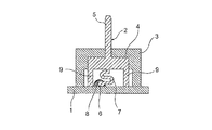
図1から図3のコネクタは、ガラスエポキシ基板などの板状の取付対象物1に搭載されるものであり、金属板材に打ち抜き加工を施して作られたコンタクト2と、コンタクト2を保持した樹脂製のハウジング3とを含んでいる。ハウジング3は、例えば略コ字状に形成され、コ字の脚部が取付対象物1に当接するように配置される。
The connector shown in FIGS. 1 to 3 is mounted on a plate-
コンタクト2は、ハウジング3のコ字の内面側に形成した凹部に圧入される圧入部4と、圧入部4からハウジング3を貫通してのび、相手側コネクタなどの接続対象物(図示せず)に接触するための接触部5と、取付対象物1に半田付け接続される接続部6と、接触部5及び接続部6の間に一体形成された応力緩和部7とを有している。圧入部4は、取付対象物1と平行に長くのびている。
The
接触部5としては、ここでは圧入部4の中央に一体形成されたピン形状のものを図示しているが、接続対象物の形態に応じてソケット形状などの他の形態のものが用いられ得る。接続部6は、取付対象物1に形成した貫通孔に挿通され、かつ取付対象物1にその裏面から半田付け部8により電気的かつ機械的に接続される。応力緩和部7は、略S字状に形成されて弾力性またはクッション性を持たされているが、他の形状によってもよい。
As the
コンタクト2は、さらに、圧入部4の両端部から取付対象物1に向かって互いに平行にのびた複数即ち2本の脚部9を有している。応力緩和部7は2本の脚部9の間に配置されている。換言すると、2本の脚部9は応力緩和部7の両側に配置されている。これらの脚部9は合わせて、応力緩和部7と並行した固定補助部を構成している。即ち、各脚部9は取付対象物1に当接し、取付対象物1に対するコネクタの固定を補助する役目を果たす。
The
このコネクタを取付対象物1にその一面側から接続部6を取付対象物1の貫通孔に挿通させつつ搭載し、そして取付対象物1の反対面側から半田付けを施して接続部6を取付対象物1の電気回路に接続させる。この状態で、相手側コネクタなどの接続対象物が接触部5に例えば嵌合接触する。この嵌合時の荷重は脚部9を介して取付対象物1に直接受けられることになるので、ハウジング3を頑丈な構造に作ることは必要ではなく、したがってコネクタの小型化が可能である。
This connector is mounted on the
ガラスエポキシ基板を取付対象物1として用い、一般的なコネクタに使用されている金属及び樹脂をコンタクト2及びハウジング3としてそれぞれ用いた場合には、これらの部分の温度変化時の膨張・収縮の差は比較的大きい。しかし、次に説明するように、これによる問題も生じない。
When a glass epoxy board is used as the
温度上昇時には、ハウジング3の膨張により、コンタクト2の圧入部4が取付対象物1から離間する向きに少し移動させられる。このとき、コンタクト2の脚部9が取付対象物1から離れようとするが、応力緩和部7が弾性変形することで、半田付け部8に過大な力が加わることは防止される。したがって、温度上昇時に半田付け部8に割れや破壊が引き起こされることはない。
When the temperature rises, the press-fitting
一方、温度下降時には、ハウジング3の収縮により、コンタクト2の圧入部4が取付対象物1に接近する向きに少し移動させられる。このとき、コンタクト2の脚部9が取付対象物1に圧接されるのみで、半田付け部8に過大な力が加わることは防止される。したがって、温度下降時に半田付け部8に割れや破壊が引き起こされることもない。
On the other hand, when the temperature drops, the press-
上述したコネクタは、温度変化に対する耐性が大であるので、自動車のエンジンルームのように氷点下から100℃以上まで温度が大幅に変動することが想定される箇所に使用することができる。 Since the connector described above is highly resistant to temperature changes, it can be used in places where the temperature is expected to fluctuate significantly from below freezing to 100 ° C. or higher, such as in the engine room of an automobile.
なお、固定補助部が2本の脚部9で構成された例について説明したが、勿論、3本以上の脚部で構成されてもよい。
In addition, although the example in which the fixing auxiliary portion is configured by the two
また、図1から図3では接続部6を取付対象物1の貫通孔に挿通させて半田付けを施しているが、図4に示すように、接続部6を取付対象物1の表面に半田付け接続することでも実施できる。
Further, in FIGS. 1 to 3, the connecting
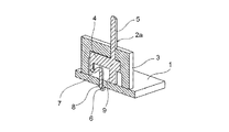
図5を参照して、本発明の第2の実施形態に係るコネクタについて説明する。図1から図3のコネクタと同様な部分については同じ参照符号を付して説明を省略する。 A connector according to a second embodiment of the present invention will be described with reference to FIG. Parts similar to those of the connector shown in FIGS. 1 to 3 are denoted by the same reference numerals and description thereof is omitted.
図5のコネクタのコンタクト2aにおいて、固定補助部は、応力緩和部7の片側に配置された一つの脚部9のみよりなる。また、脚部9と接触部5は一直線上に配置されている。これによっても、相手側コネクタなどの接続対象物の嵌合時の荷重は、脚部9を介して取付対象物1に直接受けられることになるので、ハウジング3を頑丈な構造に作ることは必要ではない。しかも、脚部9の数が減少するので、コネクタのさらなる小型化が可能である。また、温度変化に対する耐性も図1から図3に示したコネクタと同様に大である。
In the
勿論、図4と同様に、接続部6が取付対象物1の表面に半田付け接続されてもよい。
Of course, as in FIG. 4, the
図6を参照して、本発明の第3の実施形態に係るコネクタについて説明する。図1から図3のコネクタと同様な部分については同じ参照符号を付して説明を省略する。図6において、一つのハウジング3に対して、図1から図3のコネクタで使用されたコンタクト2を一列に多数並べて保持させている。このように、コンタクト2を複数用いたコネクタとしても実施することができる。
A connector according to a third embodiment of the present invention will be described with reference to FIG. Parts similar to those of the connector shown in FIGS. 1 to 3 are denoted by the same reference numerals and description thereof is omitted. In FIG. 6, a large number of
なお、応力緩和部7の構造や形状については様々な変形が可能であることはいうまでもない。
In addition, it cannot be overemphasized that various deformation | transformation is possible about the structure and shape of the
又、本発明の実施例ではコンタクトはハウジングに保持されているが、ハウジングがなくても、即ち、コンタクト単体でも実施することができる。 In the embodiment of the present invention, the contact is held by the housing. However, the contact can be implemented without the housing, that is, the contact alone.
上述したコネクタは、様々な用途にも適用できるが、特に、自動車のエンジンルームのように氷点下から100℃以上まで温度が変動する箇所に使用するのに適する。 The above-described connector can be applied to various uses, but is particularly suitable for use in a location where the temperature varies from below freezing to 100 ° C. or more, such as in an automobile engine room.
1 取付対象物
2,2a コンタクト
3 ハウジング
4 圧入部
5 接触部
6 接続部
7 応力緩和部
8 半田付け部
9 脚部
DESCRIPTION OF
Claims (6)
Priority Applications (1)
| Application Number | Priority Date | Filing Date | Title |
|---|---|---|---|
| JP2008172521A JP4801698B2 (en) | 2008-07-01 | 2008-07-01 | Connectors and contacts |
Applications Claiming Priority (1)
| Application Number | Priority Date | Filing Date | Title |
|---|---|---|---|
| JP2008172521A JP4801698B2 (en) | 2008-07-01 | 2008-07-01 | Connectors and contacts |
Publications (2)
| Publication Number | Publication Date |
|---|---|
| JP2010015722A true JP2010015722A (en) | 2010-01-21 |
| JP4801698B2 JP4801698B2 (en) | 2011-10-26 |
Family
ID=41701672
Family Applications (1)
| Application Number | Title | Priority Date | Filing Date |
|---|---|---|---|
| JP2008172521A Active JP4801698B2 (en) | 2008-07-01 | 2008-07-01 | Connectors and contacts |
Country Status (1)
| Country | Link |
|---|---|
| JP (1) | JP4801698B2 (en) |
Cited By (1)
| Publication number | Priority date | Publication date | Assignee | Title |
|---|---|---|---|---|
| JP2016100215A (en) * | 2014-11-21 | 2016-05-30 | 矢崎総業株式会社 | Terminal for substrate and substrate with terminal |
Citations (5)
| Publication number | Priority date | Publication date | Assignee | Title |
|---|---|---|---|---|
| JPH0594977U (en) * | 1992-05-28 | 1993-12-24 | 日本航空電子工業株式会社 | Connector pin |
| JPH08222292A (en) * | 1995-02-16 | 1996-08-30 | Yazaki Corp | Terminal for printed circuit board |
| JPH09200926A (en) * | 1996-01-20 | 1997-07-31 | Denso Corp | Electric connection box |
| JP2002100427A (en) * | 2000-09-25 | 2002-04-05 | Calsonic Kansei Corp | Terminal for connecting wiring board |
| JP2007234549A (en) * | 2006-03-03 | 2007-09-13 | Toyota Industries Corp | Electronic apparatus |
-
2008
- 2008-07-01 JP JP2008172521A patent/JP4801698B2/en active Active
Patent Citations (5)
| Publication number | Priority date | Publication date | Assignee | Title |
|---|---|---|---|---|
| JPH0594977U (en) * | 1992-05-28 | 1993-12-24 | 日本航空電子工業株式会社 | Connector pin |
| JPH08222292A (en) * | 1995-02-16 | 1996-08-30 | Yazaki Corp | Terminal for printed circuit board |
| JPH09200926A (en) * | 1996-01-20 | 1997-07-31 | Denso Corp | Electric connection box |
| JP2002100427A (en) * | 2000-09-25 | 2002-04-05 | Calsonic Kansei Corp | Terminal for connecting wiring board |
| JP2007234549A (en) * | 2006-03-03 | 2007-09-13 | Toyota Industries Corp | Electronic apparatus |
Cited By (4)
| Publication number | Priority date | Publication date | Assignee | Title |
|---|---|---|---|---|
| JP2016100215A (en) * | 2014-11-21 | 2016-05-30 | 矢崎総業株式会社 | Terminal for substrate and substrate with terminal |
| CN105633659A (en) * | 2014-11-21 | 2016-06-01 | 矢崎总业株式会社 | Substrate terminal and substrate with terminal |
| US9774118B2 (en) | 2014-11-21 | 2017-09-26 | Yazaki Corporation | Substrate terminal and substrate with terminal |
| CN105633659B (en) * | 2014-11-21 | 2018-04-06 | 矢崎总业株式会社 | Substrate terminal and the substrate with terminal |
Also Published As
| Publication number | Publication date |
|---|---|
| JP4801698B2 (en) | 2011-10-26 |
Similar Documents
| Publication | Publication Date | Title |
|---|---|---|
| TWI550962B (en) | Connector | |
| JP5517180B2 (en) | Contact spring for plug connector socket | |
| JP5701682B2 (en) | Electrical connection device for LED substrate | |
| US20140087572A1 (en) | Plug connector for direct contacting on a circuit board | |
| JP2006269169A (en) | Connector for connecting base | |
| JP6349346B2 (en) | Contact and connector using the contact | |
| JP2016072222A (en) | connector | |
| JP2005129275A (en) | Connector fixing structure | |
| JP2011507169A (en) | Solder connection element | |
| WO2010131543A1 (en) | Contact and electric connector | |
| US10116071B2 (en) | Electrical connector and contacts thereof | |
| US6402567B1 (en) | Electrical connector having improved spring contact member | |
| JP2014191882A (en) | Electric connector | |
| JP3190875U (en) | Relay assembly with fastening clip | |
| JP2007109600A (en) | Floating connector | |
| JP4801698B2 (en) | Connectors and contacts | |
| US7837512B1 (en) | Audio jack connector | |
| KR20190084721A (en) | Terminal Lug for contacting Circuit | |
| US8279028B2 (en) | Electromagnetic relay | |
| US7284999B1 (en) | Electrical connector | |
| JP2009524906A (en) | connector | |
| CN114514657A (en) | Connector and connector assembly | |
| KR101687228B1 (en) | Terminal | |
| JP5681261B1 (en) | PCB mounting terminals | |
| US20230354519A1 (en) | Component for surface soldering installation on a circuit board, associated use and assembly |
Legal Events
| Date | Code | Title | Description |
|---|---|---|---|
| A977 | Report on retrieval |
Free format text: JAPANESE INTERMEDIATE CODE: A971007 Effective date: 20110302 |
|
| A131 | Notification of reasons for refusal |
Free format text: JAPANESE INTERMEDIATE CODE: A131 Effective date: 20110518 |
|
| A521 | Request for written amendment filed |
Free format text: JAPANESE INTERMEDIATE CODE: A523 Effective date: 20110707 |
|
| TRDD | Decision of grant or rejection written | ||
| A01 | Written decision to grant a patent or to grant a registration (utility model) |
Free format text: JAPANESE INTERMEDIATE CODE: A01 Effective date: 20110727 |
|
| A01 | Written decision to grant a patent or to grant a registration (utility model) |
Free format text: JAPANESE INTERMEDIATE CODE: A01 |
|
| A61 | First payment of annual fees (during grant procedure) |
Free format text: JAPANESE INTERMEDIATE CODE: A61 Effective date: 20110805 |
|
| FPAY | Renewal fee payment (event date is renewal date of database) |
Free format text: PAYMENT UNTIL: 20140812 Year of fee payment: 3 |
|
| R150 | Certificate of patent or registration of utility model |
Ref document number: 4801698 Country of ref document: JP Free format text: JAPANESE INTERMEDIATE CODE: R150 Free format text: JAPANESE INTERMEDIATE CODE: R150 |
|
| R250 | Receipt of annual fees |
Free format text: JAPANESE INTERMEDIATE CODE: R250 |
|
| R250 | Receipt of annual fees |
Free format text: JAPANESE INTERMEDIATE CODE: R250 |
|
| R250 | Receipt of annual fees |
Free format text: JAPANESE INTERMEDIATE CODE: R250 |
|
| R250 | Receipt of annual fees |
Free format text: JAPANESE INTERMEDIATE CODE: R250 |
|
| R250 | Receipt of annual fees |
Free format text: JAPANESE INTERMEDIATE CODE: R250 |
|
| R250 | Receipt of annual fees |
Free format text: JAPANESE INTERMEDIATE CODE: R250 |
|
| R250 | Receipt of annual fees |
Free format text: JAPANESE INTERMEDIATE CODE: R250 |
|
| R250 | Receipt of annual fees |
Free format text: JAPANESE INTERMEDIATE CODE: R250 |
|
| R250 | Receipt of annual fees |
Free format text: JAPANESE INTERMEDIATE CODE: R250 |