JP2010015534A - Method and apparatus for simulating multicore microcomputer-based system - Google Patents
Method and apparatus for simulating multicore microcomputer-based system Download PDFInfo
- Publication number
- JP2010015534A JP2010015534A JP2008332187A JP2008332187A JP2010015534A JP 2010015534 A JP2010015534 A JP 2010015534A JP 2008332187 A JP2008332187 A JP 2008332187A JP 2008332187 A JP2008332187 A JP 2008332187A JP 2010015534 A JP2010015534 A JP 2010015534A
- Authority
- JP
- Japan
- Prior art keywords
- core
- model
- controller
- controller model
- microcomputer system
- Prior art date
- Legal status (The legal status is an assumption and is not a legal conclusion. Google has not performed a legal analysis and makes no representation as to the accuracy of the status listed.)
- Granted
Links
Images


Classifications
-
- G—PHYSICS
- G06—COMPUTING; CALCULATING OR COUNTING
- G06F—ELECTRIC DIGITAL DATA PROCESSING
- G06F30/00—Computer-aided design [CAD]
- G06F30/30—Circuit design
- G06F30/32—Circuit design at the digital level
- G06F30/33—Design verification, e.g. functional simulation or model checking
-
- G—PHYSICS
- G06—COMPUTING; CALCULATING OR COUNTING
- G06F—ELECTRIC DIGITAL DATA PROCESSING
- G06F2115/00—Details relating to the type of the circuit
- G06F2115/10—Processors
Abstract
Description
本発明はマルチコアマイコンシステムの開発方法および開発装置に関する。 The present invention relates to a development method and a development apparatus for a multi-core microcomputer system.
多くのアプリケーションがマイクロコンピュータ(マイコン)を用いたコントローラを有しており、マイコンは装置と呼ばれるデバイスを制御するために用いられる。例えば、自動車産業においてはマイコンはエンジンスロットルの駆動制御に用いられる。この場合、エンジンスロットルが装置を構成する。 Many applications have a controller using a microcomputer (microcomputer), and the microcomputer is used to control a device called an apparatus. For example, in the automobile industry, microcomputers are used for engine throttle drive control. In this case, the engine throttle constitutes the device.
そのようなマイコン制御システムの開発を容易にするために、従来用いられてきたのがシミュレーションプログラムや開発プログラムであり、これは制御システムの動作をシミュレートする。これらの既知のプログラムは実際のコントローラを実際の装置で用いる。プログラム制御によりコントローラは制御信号を装置に送り、所定の動作を実行させる。 In order to facilitate the development of such a microcomputer control system, a simulation program and a development program have been conventionally used, which simulate the operation of the control system. These known programs use an actual controller in an actual device. Under the program control, the controller sends a control signal to the apparatus to execute a predetermined operation.
マルチコアマイコンシステムの開発の一部として常に必要なのは、コントローラで実行するプログラムのデバッグと微調整である。これは従来コントローラのプログラムコードにブレークポイント(強制実行停止コード)を設けて行ってきた。コントローラ内でブレークポイントに行き当たるとプログラムの実行が停止し、プログラマはコントローラモデルと装置モデルの種々のパラメータをチェックできる。これらパラメータは内部レジスタ値、入出力信号状態、インターラプト状態、パラメータ値等を含む。 What is always required as part of the development of a multi-core microcomputer system is debugging and fine-tuning the program running on the controller. This has been done by providing breakpoints (forced execution stop code) in the program code of the conventional controller. When a breakpoint is encountered in the controller, program execution stops and the programmer can check various parameters of the controller model and device model. These parameters include internal register values, input / output signal states, interrupt states, parameter values, and the like.
システムの所望の動作が得られればブレークポイントは一般に除去され、さらにコントローラ及び装置のデバッグと微調整が反復して実施される。例えば、コントローラプログラムの特定部分が微調整及びデバッグされブレークポイントが削除されたとき、全プログラムの所望の装置モデル動作が完成するようデバッグ及び微調整されるまで、ブレークポイントをコントローラプログラムの他の部分に挿入することが必要となる。 Breakpoints are generally removed once the desired operation of the system is obtained, and further debugging and fine tuning of the controller and device is performed iteratively. For example, when a particular part of the controller program is fine-tuned and debugged and a breakpoint is deleted, breakpoints can be moved to other parts of the controller program until the desired device model behavior of the entire program is debugged and fine-tuned. It is necessary to insert into the.
上記のコントローラ及び装置を開発する従来方法の主な欠点は、少なくとも一つのブレークポイントのコントローラプログラムへの挿入は、コントローラのプログラミングの変更を要するため障害になるということである。すなわち、そのようなコントローラプログラミングの変更は、一方で所望せず予期しない動作変更をコントローラや装置に引き起こすことがある。そのような所望せず予期しない動作変更は、追加のデバッグ及び微調整をマイコン制御システム全体に要求する。 The main drawback of the conventional method of developing the above controller and apparatus is that the insertion of at least one breakpoint into the controller program is an obstacle because it requires a change in the controller programming. That is, such controller programming changes, on the other hand, can cause undesired and unexpected behavior changes in the controller or device. Such undesired and unexpected behavior changes require additional debugging and fine tuning throughout the microcomputer control system.
従来の装置制御用マイコンでは、一般的に単一のコア(CPU)を備えていた。しかし最近のマイコンは複数のコアを備えている。例えば、デュアルコアマイコンは2つの独立したコアを有し、各々が独立かつ同時に各々のコンピュータプログラムを実行する。マルチコアマイコンはシングルコアマイコンに比べ動作速度が優れており、そのプログラミング及びデバッグは新しい課題を提示している。例えば、特許文献1には、プロセッサにマルチコアを用いたマルチコアモデルのシミュレーション方法が開示され、コアモデル処理とコアモデル間の通信処理を並列に行う例が開示されている。
Conventional device control microcomputers generally have a single core (CPU). However, recent microcomputers have multiple cores. For example, a dual core microcomputer has two independent cores, each of which executes each computer program independently and simultaneously. Multi-core microcomputers are faster than single-core microcomputers, and programming and debugging present new challenges. For example,
例えば、適切なマルチコアマイコンシステムのプログラミングとデバッグには、所定時間内に実行される命令の数がほぼ同じであることが非常に望ましい。そうでなければ、マルチコアマイコンシステムの全体的な効率が損なわれる。 For example, for proper multicore microcomputer system programming and debugging, it is highly desirable that the number of instructions executed in a given time be approximately the same. Otherwise, the overall efficiency of the multicore microcomputer system is compromised.
従来知られていたマルチコアマイコンシステムのデバッグを正確に行う開発装置は、マルチコアマイコンシステムの実行を正確に反映していた。その場合、マルチコアマイコンシステムの開発は、シングルコアマイコン制御システム用の開発システムをマルチコアマイコンの各々のコアに適用していた。しかしながら、これはマイコンの各コア間に存在する相互作用を考慮しておらず、マルチコアマイコンシステムのデバッグに不正確さをもたらした。 Conventionally known development devices that accurately debug a multi-core microcomputer system accurately reflect the execution of the multi-core microcomputer system. In that case, in the development of the multi-core microcomputer system, the development system for the single-core microcomputer control system was applied to each core of the multi-core microcomputer. However, this did not take into account the interactions that exist between the cores of the microcomputer, which resulted in inaccuracies in debugging multi-core microcomputer systems.
本発明は、マルチコアマイコンシステムの開発方法及び開発装置であって、上述した従来方法及び装置の欠点を解決するものを提供する。 The present invention provides a development method and development apparatus for a multi-core microcomputer system, which solves the above-mentioned drawbacks of the conventional method and apparatus.
要するに、本発明の方法は、少なくとも一つのパラメータを持つコントローラモデルと少なくとも一つのパラメータを持ち前記コントローラモデルで制御される装置モデルをシミュレートする。これらのパラメータは、コントローラモデルのマルチコアのレジスタ値を含み、コントローラモデル及び装置モデルの入出力状態を含み、各コアの内部パラメータ値とシステムの全状態を示す他のファクタを含む。 In short, the method of the present invention simulates a controller model having at least one parameter and a device model having at least one parameter and controlled by the controller model. These parameters include multi-core register values for the controller model, input / output states for the controller model and device model, and include internal parameter values for each core and other factors that indicate the overall state of the system.
コントローラモデルと装置モデルのコアパラメータにアクセスするユーザインターフェイスが用いられる。シミュレーションの間、ユーザインターフェイスは、トリガーイベントに応じてコントローラモデルと装置モデルの実行を保留する。トリガーイベントは、装置モデルまたはコントローラモデルの条件、割り当て時間でもよく、ユーザインターフェイス経由で与えられても良い。 A user interface is used to access the core parameters of the controller model and device model. During the simulation, the user interface suspends execution of the controller model and device model in response to a trigger event. The trigger event may be a condition of the device model or the controller model, an allocation time, or may be given via a user interface.
コントローラモデルと装置モデルの実行を保留する間、ユーザインターフェイスは、コントローラモデルパラメータまたは装置モデルパラメータのいずれも変更することなく、コントローラモデルのマルチコアのパラメータ及び装置モデルパラメータを決定する。 While deferring execution of the controller model and the device model, the user interface determines the multi-core parameters of the controller model and the device model parameters without changing either the controller model parameters or the device model parameters.
コントローラモデルと装置モデルのプログラム実行の保留は目立たずに行われ、言い換えればブレークポイントのコントローラモデルプログラムへの挿入によるコントローラプログラムの変更がないため、そのようなブレークポイントの導入により生じうる所望せず予期しないエラーの導入が回避できる。 The suspension of program execution of the controller model and the device model is made inconspicuous, in other words, since there is no change in the controller program due to the insertion of breakpoints into the controller model program, such an undesired possibility that can arise from the introduction of such breakpoints The introduction of unexpected errors can be avoided.
コントローラモデルのマルチコアおよび装置モデルのための多種パラメータの値は、ユーザインターフェイスによりメモリに記憶され、選択的にディスプレイに表示される。多種パラメータの値に加えて、他の値、例えばマルチコアマイコンシステムの各コアの負荷値も同様に保存され、表示される。 Multi-parameter values for controller model multi-core and device models are stored in memory by the user interface and selectively displayed on the display. In addition to the values of the various parameters, other values such as the load value of each core of the multi-core microcomputer system are similarly stored and displayed.
このように、マルチコアマイコンの各コアのプログラムは、マイコンの各コアの負荷をバランスさせ、各コアの負荷がほぼ同じになるように実行される。 As described above, the program of each core of the multi-core microcomputer is executed so that the load of each core of the microcomputer is balanced, and the load of each core becomes substantially the same.
本発明は上記のように、一旦トリガーイベントが生じたとき、ブレークポイントをコントローラモデルのコア用プログラムコードへ挿入せずにシミュレーションの保留または停止が発生し、コントローラモデルまたは装置モデルのいかなるパラメータ値への影響も与えない。さらにコントローラモデルのマルチコアのコンピュータコードデバック量を最小にする。 As described above, according to the present invention, once a trigger event occurs, the simulation is suspended or stopped without inserting a breakpoint into the core model program code of the controller model, and any parameter value of the controller model or device model is set. The influence of. In addition, the controller model multi-core computer code debug amount is minimized.
さらに、各コアへの種々のソフトウェアの負荷などの種々の計算値もまたプログラマに表示され、プログラマがコントローラの最適効率のためにコアプログラミングを調整することを可能にする。 In addition, various calculated values, such as various software loads on each core, are also displayed to the programmer, allowing the programmer to adjust the core programming for optimal efficiency of the controller.
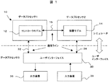
図1は、本発明の好適な実施例における、マルチコアマイコンシステムの開発装置10のブロック図を示す。マルチコアマイコンから構成されるコントローラモデル12はプログラム制御下で作動し、少なくとも一つの制御ライン16により装置モデル14の動作を制御する。装置モデル14はマイコン制御のどの対象でもよく、自動車産業における装置モデルは電子制御スロットル弁でもよい。そのその装置モデルにおいて、コントローラモデル12は動作制御すなわちスロットル弁の開閉制御を行う。
FIG. 1 shows a block diagram of a multi-core microcomputer
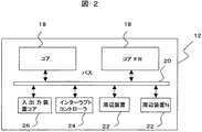
図2は、コントローラモデル12のブロック図を示す。コントローラモデル12は少なくとも二つ乃至N個のコア18を有し、各コア18はCPUを構成する。各コア18はさらにバス20を介して少なくとも一つの周辺モジュール22と交信する。バス20はインターラプトコントローラ24と交信しても良く、入出力ポート26と交信しても良い。
FIG. 2 shows a block diagram of the
マルチコア18を有するマルチコアマイコンシステムからなるコントローラモデル12において、各コア18は独立に各々のコンピュータプログラムを他のコア18と同時に実行する。全てのコアは共通データバス20を共有しており、二つ以上のコア18が同時にデータバス20にアクセス要求した場合は、データバス20が再びアイドル状態のコア18からデータを受ける自由状態に戻るまで一つまたはそれ以上のコア18がアイドル状態に入る。
In the
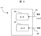
図3は、電子スロットル制御としての装置モデル14のブロック図を示す。そのような装置モデル14は、ライン44に示すモータ電流とトルクのようなパラメータを持つシミュレートされたモータ40を有する。装置モデル14はまたシミュレートされたセンサ46を有し、スロットルプレートの角度を示すシミュレートされた出力48を有する。ライン44、48の値は装置モデル14のパラメータを構成し、これはコントローラモデル12の命令に応じて変化する。
FIG. 3 shows a block diagram of the
図1において、プロセッサを有するユーザインターフェイス30はコントローラモデル12と入出力ライン32を介して通信する。同時に、ユーザインターフェイス30は入出力ライン34を介して装置モデル14と通信する。ユーザインターフェイス30はまた、ビデオモニタ、プリンタ、データ記憶装置等の出力装置36と通信し、システムオペレータがコントローラ12と装置モデル14の間の全システムシミュレーションの結果を分析することを可能とする。同時に、マウス、キーボード等の入力装置38もまた、ユーザインターフェイス30と通信し、システムオペレータに全システムシミュレーションの実行を制御させる。
In FIG. 1, a
ユーザインターフェイス30とコントローラ12、装置モデル14を結ぶ通信ライン32、34は、ユーザインターフェイス30を介してシステムオペレータにコントローラ12、装置モデル14の種々のパラメータへのアクセスを可能とする。加えて、通信ライン32、34はユーザインターフェイス30に、コントローラモデル12、装置モデル14のどのパラメータ値も変えずに、コントローラモデル12と装置モデル14の実行を保留させることができる。
さらに、シミュレートされたコントローラモデル12と装置モデル14の実行保留の間、システムオペレータは図2に示すコントローラモデル12内の各コア18の種々のパラメータ、または図3に示す装置モデル14の種々のパラメータを、これらパラメータの値を変えずに取り出すことができる。従って、各コア18のためのコントローラプログラムシミュレーションの実行再開において、コントローラモデル12は、コントローラモデル12と装置モデル14の実行保留によりシステムのシミュレーションに影響を与えることなく、実行を継続することができる。
In addition, during the pending execution of the simulated
図1のブロック図において、コントローラモデル12と装置モデル14を有するシミュレータおよびユーザインターフェイス30は、コントローラモデル12と装置モデル14およびユーザインターフェイス30用の個別のデータプロセッサ1、2、3を用いて実行される。
In the block diagram of FIG. 1, a simulator and
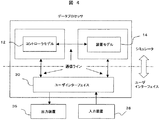
しかし、コントローラモデル12と装置モデル14およびユーザインターフェイス30はかならずしも個別のプロセッサを用いる必要は無い。代わりに、図4に示すように、単一のデータプロセッサのコンピュータシステムが、コントローラモデル12や装置モデル14、インターフェイス30の実行のために用いられても良い。
However, the
図5A〜Dにおいて、全システムのシミュレーション出力の例が図示され、図1に示すビデオディスプレイ等の出力装置36に表示される。例えば図5Aにおいてテーブル100はコントローラモデル12の各コアのために表示され、ここで各テーブル100はコントローラの特定コアに関連する種々のパラメータと算出値を含む。
5A to 5D, an example of the simulation output of the entire system is shown and displayed on the
上記テーブル100は、コア18の一つで実行される実行コードを示すTASK、IDLE、OS等のカテゴリー名を有する。テーブル100はまた、各カテゴリーのコール回数や、命令数、消費されたサイクル数、負荷率を含む。例えばコントローラ12の第1コア(CPU#1)に示すように、カテゴリー「タスク」は第1コア時間の55%を消費し、「IDLE」には5000コールがあり第1コア時間の35%を消費する等である。
The table 100 has category names such as TASK, IDLE, and OS indicating execution codes executed by one of the
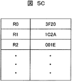
図5B〜5Dは、出力デバイス36の全マルチコアマイコンシステムのシミュレーションの他の例示出力を示す。例えば、図5Bはコントローラモデル12または装置モデル14のコアの一つにおけるパラメータ値を示すグラフである。図5Cはコントローラ12のコアの一つのレジスタ値テーブルを示す。図5Dはコントローラ12のコア18で現在実行中のアセンブリコードテーブルを示す。
FIGS. 5B to 5D show other exemplary outputs of simulation of the entire multi-core microcomputer system of the
例えば、図5Dで、アドレス000000はコード0F9Aをストアし、レジスタR0、R1を図5Cのテーブル中でADDする。アドレス000002はコードC003をストアし、レジスタR1の値をテーブル中でメモリのR3に移動する。アドレス000004はコード28DBをストアし、テーブル中でレジスタR2とR3の値を掛ける。アドレス000006はコードF35Eをストアし、テーブル中でレジスタのR4にジャンプする。
For example, in FIG. 5D,
テーブル100の負荷率は計算値であり、一方テーブル100の他の情報はコントローラモデルの種々のパラメータに関係する。また、他の異なるテーブル100がコントローラ12の各コアについて生成され、この複数のテーブル100は必要に応じ同時に表示される。他のタイプの表示たとえばグラフもインターフェイス30で表示可能である。
The load factor of the table 100 is a calculated value, while other information in the table 100 relates to various parameters of the controller model. Another different table 100 is generated for each core of the
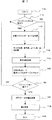
図6に示すフローチャートには、コントローラ12の各コア18のテーブル100の生成に関する本実施例の動作が記載される。プログラムはステップ110でスタートし、すぐにステップ112に進む。ステップ112ではプログラムは、コアがファンクションコール命令を実行中か否かを決定する。もし実行していない場合はステップ112はステップ114に分岐する。
The flowchart shown in FIG. 6 describes the operation of the present embodiment relating to the generation of the table 100 of each core 18 of the
もしステップ112でコアがファンクションコール命令を実行している場合は、ステップ112はステップ116に進みファンクションコールIDまたはアドレスが決定される。次いでステップ116はステップ114に進む。
If the core is executing a function call instruction at
ステップ114において、インターフェイス30はコントローラモデルの一つのコア18のサイクル数と命令数を計算し、ステップ115に進む。
In
ステップ115で、インターフェイス30は、コントローラモデルのコア18で処理される各カテゴリーの命令および機能名の負荷率を計算する。ステップ115は次いでステップ118に進み、値が例えば表示装置に表示されまたはメモリに保存される。ステップ118は次いでステップ120に進み、コントローラモデルのコア18のための次の命令がステップ112に戻って処理され、上記ステップが次の命令のために反復される。
At
図6のフローチャートは、当然ながらコントローラモデル12の各コア18につき反復される。この方法で図5に示すテーブル100がコントローラモデル12の各コア18につき生成され表示装置に表示されても良い。
The flowchart of FIG. 6 is of course repeated for each core 18 of the
これはプログラマがコントローラモデル12の種々のコア18に対しプログラミングを調整し、これにより全てのコア18への負荷率をほぼ同一にすることを可能にする。この方法によりコントローラモデル12の種々のコア18の計算能力は、コントローラモデルの効率的動作とほぼ同一となる。
This allows the programmer to adjust the programming for the
図7において、図6のフローチャートの変形例が示されている。図7のフローチャートは、シミュレーションの最後におけるコントローラモデル12の全てのコア18の種々のファクタとパラメータの総計を示す。
FIG. 7 shows a modification of the flowchart of FIG. The flowchart of FIG. 7 shows the sum of various factors and parameters of all the
更に詳細に言えば、プログラムはステップ115の負荷率計算の後でステップ140に進み、命令のカテゴリー名を決定する。カテゴリー名を決定するためにいずれかの公知の手段、例えばルックアップテーブルが用いられても良い。
More specifically, the program proceeds to step 140 after the load factor calculation of
ステップ142で、プログラムはシミュレーションが終了したか決定する。もし終了していなければ、ステップ142はステップ112に戻り、ステップ112で開始された処理が各コア18の次の命令のために反復される。
In
反対に、シミュレーションが終了したと仮定した場合、ステップ142は代わりにステップ144に進み、コントローラモデル12の各コア18の負荷率を含む種々の演算カテゴリーの全体の値が決定される。ステップ144は次いでステップ118に進み、それらの値を表示し、ステップ146に進み、シミュレーションが終了する。
Conversely, assuming that the simulation is complete, step 142 instead proceeds to step 144 where the overall values of the various operational categories including the load factor of each core 18 of the
動作中に、シミュレーションはユーザインターフェイス30の制御の下に実行される。シミュレーションの間、シミュレーション速度はユーザインターフェイス30により例えばクロック信号速度を変更する等で制御される。
During operation, the simulation is performed under the control of the
シミュレーションはトリガーイベントが検出されるまで継続する。トリガーイベントはユーザによりユーザインターフェイス30を介して起動され、またはコア18の一つの特定レジスタ値が所定条件になったとき等に、ユーザインターフェイス30により起動される。
The simulation continues until a trigger event is detected. The trigger event is activated by the user via the
トリガーイベントが発生するいずれのイベントでも、インターフェイス30はコントローラモデル12および装置モデル14へのクロック信号を停止してシステムシミュレーションを保留する。このとき、図6及び図7に記載されたプログラムが実行され、コントローラモデル12の種々のコア18の種々のパラメータ及び装置モデル14のパラメータが表示装置に表示される。
In any event where a trigger event occurs,
言うまでもなくコントローラ及び装置モデルシミュレーション動作の保留に多数の異なるタイプのトリガーイベントを用いることができ、コントローラモデル及び装置モデルの種々のパラメータが表示装置に表示される。 Needless to say, many different types of trigger events can be used to defer controller and device model simulation operations, and various parameters of the controller model and device model are displayed on the display device.
例えば、このトリガーイベントは、装置モデルまたはコントローラモデルの少なくとも一つのレジスタの所定値とすることができる。同様に、コントローラモデルのインターラプト状態もトリガーイベントを構成できる。同様に、装置モデルまたはコントローラの種々のパラメータがトリガーイベントを構成できる。 For example, the trigger event can be a predetermined value of at least one register of the device model or the controller model. Similarly, the interrupt state of the controller model can also constitute a trigger event. Similarly, various parameters of the device model or controller can constitute the trigger event.
本実施例の重要な長所は、一旦トリガーイベントが生じたとき、ブレークポイントをコントローラモデル12のコア18用プログラムコードへ挿入せずにシミュレーションの保留または停止が発生し、コントローラモデルまたは装置モデルのいかなるパラメータ値への影響も与えないことである。これは、同様にコントローラモデル12のコア18のためのコンピュータコードデバック量を最小にする。
An important advantage of this embodiment is that once a trigger event occurs, the simulation is suspended or stopped without inserting a breakpoint into the program code for the
図8はマルチコアマイコンの各コア(CPU#1、#2、…#N)のテーブル100における表示を示す。マルチコアマイコンの一つのコアを選択して新しいタスクを処理させるには、各カテゴリー(TASK:タスク、ISR:インターラプトルーチン、OS:オペレーションシステム、IDLE:アイドル)の負荷率が各コアにつき計算される。
FIG. 8 shows a display in the table 100 of each core (
優先度が低く通常優先度のプログラムにインパクトを与えないアイドル動作、たとえばOSスケジューラによりジョブのない時に負荷されたアイドルタスク、の負荷率が各カテゴリーのプロセッサ占有度によって計算される。アイドル動作で最も高い負荷率を持つコアがマルチコアのいずれにも指定されていない新しいタスク処理能力を持つことになる。 A load factor of an idle operation having a low priority and no impact on a normal priority program, for example, an idle task loaded when there is no job by the OS scheduler, is calculated based on the processor occupancy of each category. The core with the highest load factor in idle operation will have a new task processing capability not specified for any of the multi-cores.
マルチコアマイコン処理プロセスは、対称マルチ処理(SMP)と非対称マルチ処理(AMP)に分けられる。SMPでは単一のOSが全てのCPUを同時に管理しアプリケーションはどのCPUにもフロート可能である。一方、AMPは個別にOSを各コアで動かし、各アプリケーションは特定コアに固定されている。 The multi-core microcomputer process is divided into a symmetric multi process (SMP) and an asymmetric multi process (AMP). In SMP, a single OS manages all CPUs simultaneously, and applications can float to any CPU. On the other hand, the AMP individually runs the OS in each core, and each application is fixed to a specific core.
上記SMPは非決定的システムであり重要なソフトウェア機能を保証応答時間内に実行することが保証されず、保証応答時間を要求する自動車産業のシステムには適当でない。従って本実施例では、各コアの実行情報はAMPプロセスを持つマルチコアを用いて計算される。 The SMP is a non-deterministic system and is not guaranteed to perform critical software functions within the guaranteed response time and is not suitable for systems in the automotive industry that require a guaranteed response time. Therefore, in this embodiment, the execution information of each core is calculated using a multi-core having an AMP process.
開発者は、設計段階で最高のパフォーマンスをあげるためにいくつかのタスクを固定プロセッサリソースに指定する必要がある。AMPの使用は各コア情報を用いた計算を必要とするが、レガシーコードの使用が容易であり、ソフトウェアのメモリやインターラプト等のシステムリソースの利用につき完全な制御を保証する。 Developers need to assign some tasks to fixed processor resources for best performance during the design phase. The use of AMP requires calculation using each core information, but the use of legacy code is easy, and complete control is guaranteed for the use of system resources such as software memory and interrupts.
本実施例において各コアでの実行情報、例えばサイクル、命令、コール等の数は、各コアに指示する前に得られる。従って各コアのアイドル負荷率が計算され比較される。これにより、最も高いアイドル負荷率を持つコアに指示された新しいタスクを得ることが可能である。従って、図8においてアイドル負荷率80%を持つ第2コア(CPU#2)が選択される。この選択はユーザのディスプレイによる選択か、あるいは自動的にプログラムが設定しマルチコアの一つに保存したルールによって可能である。 In this embodiment, execution information in each core, such as the number of cycles, instructions, calls, etc., is obtained before instructing each core. Therefore, the idle load factor of each core is calculated and compared. As a result, it is possible to obtain a new task directed to the core having the highest idle load ratio. Accordingly, the second core (CPU # 2) having an idle load factor of 80% is selected in FIG. This selection can be made by the user's display, or by rules automatically set by the program and stored in one of the multicores.
上述のように、本発明は、マルチコアマイコンシステムの開発装置と方法を提供し、それは、シミュレーションにおいてマルチコアマイコンコントローラおよび装置の全てのコアの種々のパラメータ状態を目立たずにモニター可能であることが明らかである。 As described above, the present invention provides a multi-core microcomputer system development apparatus and method, which can clearly monitor various parameter states of all cores of a multi-core microcomputer controller and apparatus in a simulation. It is.
さらに、各コアへの種々のソフトウェアの負荷などの種々の計算値もまたプログラマに表示され、プログラマがコントローラの最適効率のためにコアプログラミングを調整することを可能にする。 In addition, various calculated values, such as various software loads on each core, are also displayed to the programmer, allowing the programmer to adjust the core programming for optimal efficiency of the controller.
以上のように本発明を説明したが、当業者に自明な多くの変形例が本発明の主旨に含まれクレーム内に含まれる。 Although the present invention has been described above, many modifications obvious to those skilled in the art are included in the gist of the present invention and included in the claims.
12:コントローラモデル
14:装置モデル
18:コア
30:ユーザインターフェイス
36:出力装置
38:入力装置
12: Controller model 14: Device model 18: Core 30: User interface 36: Output device 38: Input device
Claims (19)
少なくとも一つのパラメータを有し前記コントローラモデルに制御される装置モデルをシミュレートするステップと、
前記コントローラモデルの各コアおよび装置モデルのパラメータにアクセスするユーザインターフェイスをシミュレートするステップと、
トリガーイベントに応じて前記ユーザインターフェイスを介してコントローラモデルの各コアおよび装置モデルの実行を保留するステップと、
前記コントローラモデルの各コアのパラメータ又は装置モデルのパラメータの少なくとも一つの状態を、前記コントローラモデル及び装置モデルのパラメータを変更することなく、前記ユーザインターフェイスを介して前記保留ステップの間に決定するステップと
からなることを特徴とするマルチコアマイコンシステムのシミュレーション方法。 Simulating each core of the controller model having at least one parameter in a controller model having a multi-core microcomputer;
Simulating a device model having at least one parameter and controlled by the controller model;
Simulating a user interface to access parameters of each core and device model of the controller model;
Suspending execution of each core and device model of the controller model via the user interface in response to a trigger event;
Determining at least one state of each core parameter or device model parameter of the controller model during the hold step via the user interface without changing the controller model and device model parameters; A simulation method for a multi-core microcomputer system, comprising:
Applications Claiming Priority (2)
| Application Number | Priority Date | Filing Date | Title |
|---|---|---|---|
| US12/164,178 | 2008-06-30 | ||
| US12/164,178 US7987075B2 (en) | 2008-06-30 | 2008-06-30 | Apparatus and method to develop multi-core microcomputer-based systems |
Publications (2)
| Publication Number | Publication Date |
|---|---|
| JP2010015534A true JP2010015534A (en) | 2010-01-21 |
| JP5270330B2 JP5270330B2 (en) | 2013-08-21 |
Family
ID=41449154
Family Applications (1)
| Application Number | Title | Priority Date | Filing Date |
|---|---|---|---|
| JP2008332187A Expired - Fee Related JP5270330B2 (en) | 2008-06-30 | 2008-12-26 | Multicore microcomputer system simulation method and simulation apparatus |
Country Status (2)
| Country | Link |
|---|---|
| US (1) | US7987075B2 (en) |
| JP (1) | JP5270330B2 (en) |
Cited By (1)
| Publication number | Priority date | Publication date | Assignee | Title |
|---|---|---|---|---|
| JP2018511850A (en) * | 2015-02-03 | 2018-04-26 | アリババ・グループ・ホールディング・リミテッドAlibaba Group Holding Limited | Apparatus, device and method for allocating CPU resources |
Families Citing this family (10)
| Publication number | Priority date | Publication date | Assignee | Title |
|---|---|---|---|---|
| CN101620548B (en) * | 2008-07-04 | 2013-03-27 | 菲尼克斯电气公司 | Method and computer system for the computer simulation of a plant or a machine |
| EP2702517A1 (en) * | 2011-04-23 | 2014-03-05 | Deubzer, Michael | Method for the design evaluation of a system |
| US8941605B2 (en) | 2011-06-16 | 2015-01-27 | Empire Technology Development Llc | Process management in a multi-core environment |
| JP5692381B2 (en) * | 2011-07-13 | 2015-04-01 | 富士通株式会社 | Multi-core processor system and control method |
| US9965279B2 (en) * | 2013-11-29 | 2018-05-08 | The Regents Of The University Of Michigan | Recording performance metrics to predict future execution of large instruction sequences on either high or low performance execution circuitry |
| US9870226B2 (en) | 2014-07-03 | 2018-01-16 | The Regents Of The University Of Michigan | Control of switching between executed mechanisms |
| US10038744B1 (en) * | 2015-06-29 | 2018-07-31 | EMC IP Holding Company LLC | Intelligent core assignment |
| US11314907B2 (en) | 2016-08-26 | 2022-04-26 | Hitachi, Ltd. | Simulation including multiple simulators |
| US10613980B2 (en) * | 2017-12-19 | 2020-04-07 | International Business Machines Corporation | Coherence protocol providing speculative coherence response to directory probe |
| CN110554912B (en) * | 2018-05-31 | 2022-05-20 | 杭州海康威视数字技术股份有限公司 | Method and device for scheduling equipment to execute tasks |
Citations (4)
| Publication number | Priority date | Publication date | Assignee | Title |
|---|---|---|---|---|
| JPH05313946A (en) * | 1992-05-06 | 1993-11-26 | Nippon Telegr & Teleph Corp <Ntt> | Debugging back-up device for multiprocessor system |
| JP2003281112A (en) * | 2002-03-25 | 2003-10-03 | Fujitsu Ltd | Multiprocessor system |
| JP2006293759A (en) * | 2005-04-12 | 2006-10-26 | Fujitsu Ltd | Multi-core model simulator |
| JP2007265415A (en) * | 2006-03-29 | 2007-10-11 | Hitachi Ltd | Method and apparatus for simulating microcomputer-based systems |
Family Cites Families (6)
| Publication number | Priority date | Publication date | Assignee | Title |
|---|---|---|---|---|
| US6081885A (en) * | 1996-12-20 | 2000-06-27 | Texas Instruments Incorporated | Method and apparatus for halting a processor and providing state visibility on a pipeline phase basis |
| US6065106A (en) * | 1996-12-20 | 2000-05-16 | Texas Instruments Incorporated | Resuming normal execution by restoring without refetching instructions in multi-word instruction register interrupted by debug instructions loading and processing |
| US6016555A (en) * | 1997-11-19 | 2000-01-18 | Texas Instruments Incorporated | Non-intrusive software breakpoints in a processor instruction execution pipeline |
| US6643803B1 (en) * | 1999-02-19 | 2003-11-04 | Texas Instruments Incorporated | Emulation suspend mode with instruction jamming |
| US6553513B1 (en) * | 1999-02-19 | 2003-04-22 | Texas Instruments Incorporated | Emulation suspend mode with differing response to differing classes of interrupts |
| US20090106001A1 (en) * | 2007-10-17 | 2009-04-23 | Atomic Energy Council - Institute Of Nuclear Energy Research | Digital I&C software failure simulation test facility |
-
2008
- 2008-06-30 US US12/164,178 patent/US7987075B2/en not_active Expired - Fee Related
- 2008-12-26 JP JP2008332187A patent/JP5270330B2/en not_active Expired - Fee Related
Patent Citations (4)
| Publication number | Priority date | Publication date | Assignee | Title |
|---|---|---|---|---|
| JPH05313946A (en) * | 1992-05-06 | 1993-11-26 | Nippon Telegr & Teleph Corp <Ntt> | Debugging back-up device for multiprocessor system |
| JP2003281112A (en) * | 2002-03-25 | 2003-10-03 | Fujitsu Ltd | Multiprocessor system |
| JP2006293759A (en) * | 2005-04-12 | 2006-10-26 | Fujitsu Ltd | Multi-core model simulator |
| JP2007265415A (en) * | 2006-03-29 | 2007-10-11 | Hitachi Ltd | Method and apparatus for simulating microcomputer-based systems |
Cited By (1)
| Publication number | Priority date | Publication date | Assignee | Title |
|---|---|---|---|---|
| JP2018511850A (en) * | 2015-02-03 | 2018-04-26 | アリババ・グループ・ホールディング・リミテッドAlibaba Group Holding Limited | Apparatus, device and method for allocating CPU resources |
Also Published As
| Publication number | Publication date |
|---|---|
| US20090327944A1 (en) | 2009-12-31 |
| JP5270330B2 (en) | 2013-08-21 |
| US7987075B2 (en) | 2011-07-26 |
Similar Documents
| Publication | Publication Date | Title |
|---|---|---|
| JP5270330B2 (en) | Multicore microcomputer system simulation method and simulation apparatus | |
| US8903703B2 (en) | Dynamically adjusting speed versus accuracy of computer platform simulation | |
| US8793115B2 (en) | Interface converter for unified view of multiple computer system simulations | |
| JP2004086910A (en) | Method, system, and software product for debugging computer program | |
| JP2003131902A (en) | Software debugger, system-level debugger, debug method and debug program | |
| US8108840B2 (en) | Method for enhancing debugger performance of hardware assisted breakpoints | |
| US20080082802A1 (en) | Microcomputer debugging system | |
| US7016826B2 (en) | Apparatus and method of developing software for a multi-processor chip | |
| CN109800166B (en) | Debugging method and device for embedded real-time operating system | |
| AU2017438670B2 (en) | Simulation device, simulation method, and simulation program | |
| JP5542643B2 (en) | Simulation apparatus and simulation program | |
| US8914274B1 (en) | Method and system for instruction set simulation with concurrent attachment of multiple debuggers | |
| JP2010244376A (en) | Software development device, and debugging method using the same | |
| KR100952762B1 (en) | Real-time debugging method of digital signal processor | |
| WO2006091785A1 (en) | Interface converter for unified view of multiple computer system simulations | |
| Hölscher et al. | Examining and Supporting Multi-Tasking in EV3OSEK | |
| JP5425445B2 (en) | Processing control system, method and program | |
| JP2002366378A (en) | Method and device for debugging program and storage medium | |
| Hölscher | Nested Preemption Fixed-Priority Scheduler for EV3OSEK | |
| KR20240009786A (en) | Operating system virtualization device and method for simulation of automotive software platform | |
| US20070150873A1 (en) | Dynamic host code generation from architecture description for fast simulation | |
| JPH05250221A (en) | Simulator execution system | |
| Foster et al. | Real-time 32-bit microcontroller with OSEK/VDX operating system support | |
| JPH11296408A (en) | Software logic simulator for incorporation unit | |
| JPH0883198A (en) | Program simulation device |
Legal Events
| Date | Code | Title | Description |
|---|---|---|---|
| A621 | Written request for application examination |
Free format text: JAPANESE INTERMEDIATE CODE: A621 Effective date: 20101101 |
|
| A977 | Report on retrieval |
Free format text: JAPANESE INTERMEDIATE CODE: A971007 Effective date: 20120214 |
|
| A131 | Notification of reasons for refusal |
Free format text: JAPANESE INTERMEDIATE CODE: A131 Effective date: 20120221 |
|
| A521 | Written amendment |
Free format text: JAPANESE INTERMEDIATE CODE: A523 Effective date: 20120419 |
|
| A131 | Notification of reasons for refusal |
Free format text: JAPANESE INTERMEDIATE CODE: A131 Effective date: 20120703 |
|
| A521 | Written amendment |
Free format text: JAPANESE INTERMEDIATE CODE: A523 Effective date: 20120827 |
|
| A02 | Decision of refusal |
Free format text: JAPANESE INTERMEDIATE CODE: A02 Effective date: 20121225 |
|
| A521 | Written amendment |
Free format text: JAPANESE INTERMEDIATE CODE: A523 Effective date: 20130321 |
|
| A911 | Transfer to examiner for re-examination before appeal (zenchi) |
Free format text: JAPANESE INTERMEDIATE CODE: A911 Effective date: 20130329 |
|
| TRDD | Decision of grant or rejection written | ||
| A01 | Written decision to grant a patent or to grant a registration (utility model) |
Free format text: JAPANESE INTERMEDIATE CODE: A01 Effective date: 20130507 |
|
| A61 | First payment of annual fees (during grant procedure) |
Free format text: JAPANESE INTERMEDIATE CODE: A61 Effective date: 20130509 |
|
| R150 | Certificate of patent or registration of utility model |
Free format text: JAPANESE INTERMEDIATE CODE: R150 Ref document number: 5270330 Country of ref document: JP Free format text: JAPANESE INTERMEDIATE CODE: R150 |
|
| LAPS | Cancellation because of no payment of annual fees |