JP2010015378A - 磁気誘導方式無人搬送車用の誘導路構造体 - Google Patents
磁気誘導方式無人搬送車用の誘導路構造体 Download PDFInfo
- Publication number
- JP2010015378A JP2010015378A JP2008174654A JP2008174654A JP2010015378A JP 2010015378 A JP2010015378 A JP 2010015378A JP 2008174654 A JP2008174654 A JP 2008174654A JP 2008174654 A JP2008174654 A JP 2008174654A JP 2010015378 A JP2010015378 A JP 2010015378A
- Authority
- JP
- Japan
- Prior art keywords
- magnetic induction
- guided vehicle
- induction band
- protective member
- automatic guided
- Prior art date
- Legal status (The legal status is an assumption and is not a legal conclusion. Google has not performed a legal analysis and makes no representation as to the accuracy of the status listed.)
- Granted
Links
- 230000006698 induction Effects 0.000 title claims abstract description 102
- 230000001681 protective effect Effects 0.000 claims description 66
- 229920000915 polyvinyl chloride Polymers 0.000 claims description 5
- 239000004800 polyvinyl chloride Substances 0.000 claims description 5
- 239000000853 adhesive Substances 0.000 claims description 4
- 230000001070 adhesive effect Effects 0.000 claims description 4
- 230000007423 decrease Effects 0.000 claims description 4
- 238000012423 maintenance Methods 0.000 abstract description 15
- 238000000034 method Methods 0.000 description 7
- 238000004519 manufacturing process Methods 0.000 description 6
- 238000005259 measurement Methods 0.000 description 6
- 239000002390 adhesive tape Substances 0.000 description 5
- 230000004907 flux Effects 0.000 description 4
- 238000009434 installation Methods 0.000 description 4
- 239000005001 laminate film Substances 0.000 description 4
- 230000000694 effects Effects 0.000 description 3
- 230000005389 magnetism Effects 0.000 description 3
- 238000005520 cutting process Methods 0.000 description 2
- 239000000463 material Substances 0.000 description 2
- 238000003860 storage Methods 0.000 description 2
- 229920003002 synthetic resin Polymers 0.000 description 2
- 239000000057 synthetic resin Substances 0.000 description 2
- 229910000859 α-Fe Inorganic materials 0.000 description 2
- 239000004709 Chlorinated polyethylene Substances 0.000 description 1
- 229910045601 alloy Inorganic materials 0.000 description 1
- 239000000956 alloy Substances 0.000 description 1
- 239000011230 binding agent Substances 0.000 description 1
- 239000003086 colorant Substances 0.000 description 1
- 239000000428 dust Substances 0.000 description 1
- 239000013013 elastic material Substances 0.000 description 1
- 230000005674 electromagnetic induction Effects 0.000 description 1
- 238000012840 feeding operation Methods 0.000 description 1
- 230000001771 impaired effect Effects 0.000 description 1
- 239000000696 magnetic material Substances 0.000 description 1
- 239000011120 plywood Substances 0.000 description 1
- 229920000642 polymer Polymers 0.000 description 1
- 239000000843 powder Substances 0.000 description 1
- 239000004065 semiconductor Substances 0.000 description 1
- 229910052712 strontium Inorganic materials 0.000 description 1
- CIOAGBVUUVVLOB-UHFFFAOYSA-N strontium atom Chemical compound [Sr] CIOAGBVUUVVLOB-UHFFFAOYSA-N 0.000 description 1
- 238000004804 winding Methods 0.000 description 1
Images


Landscapes
- Control Of Position, Course, Altitude, Or Attitude Of Moving Bodies (AREA)
Abstract
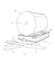
【解決手段】床面Fに敷設され磁気誘導方式の無人搬送車1を誘導する磁気誘導帯L1を有し、無人搬送車1が磁気誘導帯L2を乗り越える場所の磁気誘導帯L2の長手方向に対して両側方に、磁気誘導帯L2と同じ厚さの保護部材S1が設置されていることにより上記の課題を解決する。
【選択図】図1
Description
ここで、図1は、実施例1の誘導路構造体が新聞印刷工場で使用されるときの一実施形態を無人搬送車とともに示した斜視図であり、図2は、本発明の誘導路構造体と無人搬送車との配置関係を説明する平面図である。また、図3(a)は、従来の誘導路構造体の形状を示す平面図であり、図3(b)は、それを無人搬送車が乗り越えた際の振動計測結果を示すグラフであり、図4(a)は、本発明の実施例1の誘導路構造体の形状を示す平面図であり、図4(b)は、それを無人搬送車が乗り越えた際の振動計測結果を示すグラフである。
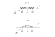
実施例2の誘導路構造体20は、図5(a)に示すように、無人搬送車のキャスタ輪及び駆動輪が磁気誘導帯Lを乗り越える場所に、磁気誘導帯Lの長手方向に対して両側方に幅が次第に広くなる直角三角形状の保護部材S2が磁気誘導帯Lの側面に接触するように設置されている。このような保護部材S2を設置した誘導路構造体20を無人搬送車が乗り越える際に発生する振動を前述と同じ条件で計測した結果を示したものが図4(b)のグラフである。このグラフが示すように、無人搬送車が誘導路構造体20を乗り越える際に、最大0.25G、最小−0.26Gの振動が計測された。したがって、保護部材S2を設置した誘導路構造体20は、前述した保護部材を有しない通常の誘導路構造体、すなわち磁気誘導帯L単体に比べて、振動の発生が20%以下に抑制されている。この理由は、無人搬送車が誘導路構造体20に乗り上げる際に、無人搬送車のキャスタ輪及び駆動輪と保護部材S2との接触面積が徐々に増加し、無人搬送車が誘導路構造体20から降りる際に、無人搬送車のキャスタ輪及び駆動輪と保護部材S2との接触面積が徐々に減少するため、乗り越え時の衝撃が軽減され、発生する振動が抑制されるためである。
本発明の誘導路構造体に設置する保護部材は、実施例1で説明した均一幅の保護部材S1及び実施例2で説明した直角三角形状の保護部材S2の他に、図6(a)乃至図6(e)に示すように、磁気誘導帯Lと保護部材S3乃至保護部材S7の外縁部との距離が、磁気誘導帯Lの長手方向に対して不均一である様々な形状を採用することができる。図6(a)乃至図6(e)に示したいずれの誘導路構造体30、40、50、60、70であっても、無人搬送車が磁気誘導帯Lに乗り上げる際に、無人搬送車のキャスタ輪及び駆動輪と保護部材S3乃至保護部材S7との接触面積が徐々に増加し、無人搬送車が磁気誘導帯Lから降りる際に、無人搬送車のキャスタ輪及び駆動輪と保護部材S3乃至保護部材S7との接触面積が徐々に減少するため、乗り越え時の衝撃が軽減され、発生する振動を抑制することができる。
実施例4の誘導路構造体80は、磁気誘導帯Lの長手方向に対して両側方に設置する保護部材S8が、実施例1乃至実施例3で説明した保護部材S1乃至保護部材S7のように磁気誘導帯の長手方向に対して両側方にそれぞれ別の保護部材が磁気誘導帯の側面に接触するように設置されているものと異なり、1つの保護部材S8が磁気誘導帯Lを覆うように設置されている。このような構造にしたことにより、磁気誘導帯Lの長手方向に対して両側方に設置される保護部材S8が単一の部材であるため、その製造工程が削減されて製造コストの低減が図られるとともに、保護部材S8の設置作業負担も軽減される。さらに、無人搬送車が磁気誘導帯Lを乗り越える場所が保護部材S8で覆われることによって、磁気誘導帯Lの表面の摩耗が抑制され誘導路構造体80の耐久性が向上する。
ここで、図8(a)は、前述した実施例2の誘導路構造体20の断面形状を示している。すなわち、図5(a)のVIII−VIII線における断面図である。このように前述した実施例1乃至実施例3の誘導路構造体は、いずれも保護部材を市販のラインテープを切断することによって作製しているので、保護部材の厚さが一定であった。
2 ・・・ キャスタ輪
3 ・・・ 駆動輪
10、20、30、40、50、60、70、80、90、100・・・誘導路構造体
L、L1、L2、L3、L4 ・・・ 磁気誘導帯
S1、S2、S3、S4、S5、S6、S7、S8、S9、S10 ・・・ 保護部材
R ・・・ 巻取紙
C ・・・ 残芯
F ・・・ 床
500 ・・・ 従来の誘導路構造体
510 ・・・ (従来の誘導路構造体の)磁気誘導帯
520 ・・・ (従来の誘導路構造体の)両面接着テープ
530 ・・・ (従来の誘導路構造体の)ラミネートフィルム
Claims (4)
- 床面に敷設され磁気誘導方式の無人搬送車を誘導する磁気誘導帯を有する誘導路構造体において、
前記無人搬送車が磁気誘導帯を乗り越える場所の該磁気誘導帯の長手方向に対して両側方に、前記磁気誘導帯と同じ厚さの保護部材が設置されていることを特徴とする誘導路構造体。 - 前記磁気誘導帯と保護部材の外縁部との距離が、磁気誘導帯の長手方向に対して不均一であることを特徴とする請求項1記載の誘導路構造体。
- 前記保護部材の厚さが、前記磁気誘導帯から離れるにつれて薄くなっていることを特徴とする請求項1又は請求項2記載の誘導路構造体。
- 前記保護部材が、表面がポリ塩化ビニル製フィルムであり裏面がゴム系粘着剤であるラインテープからなることを特徴とする請求項1乃至請求項3のいずれか記載の誘導路構造体。
Priority Applications (1)
| Application Number | Priority Date | Filing Date | Title |
|---|---|---|---|
| JP2008174654A JP5127601B2 (ja) | 2008-07-03 | 2008-07-03 | 磁気誘導方式無人搬送車用の誘導路構造体 |
Applications Claiming Priority (1)
| Application Number | Priority Date | Filing Date | Title |
|---|---|---|---|
| JP2008174654A JP5127601B2 (ja) | 2008-07-03 | 2008-07-03 | 磁気誘導方式無人搬送車用の誘導路構造体 |
Publications (2)
| Publication Number | Publication Date |
|---|---|
| JP2010015378A true JP2010015378A (ja) | 2010-01-21 |
| JP5127601B2 JP5127601B2 (ja) | 2013-01-23 |
Family
ID=41701442
Family Applications (1)
| Application Number | Title | Priority Date | Filing Date |
|---|---|---|---|
| JP2008174654A Active JP5127601B2 (ja) | 2008-07-03 | 2008-07-03 | 磁気誘導方式無人搬送車用の誘導路構造体 |
Country Status (1)
| Country | Link |
|---|---|
| JP (1) | JP5127601B2 (ja) |
Citations (1)
| Publication number | Priority date | Publication date | Assignee | Title |
|---|---|---|---|---|
| JP2003195942A (ja) * | 2001-12-26 | 2003-07-11 | Nippon Yusoki Co Ltd | 無人搬送車のガイド線構造 |
-
2008
- 2008-07-03 JP JP2008174654A patent/JP5127601B2/ja active Active
Patent Citations (1)
| Publication number | Priority date | Publication date | Assignee | Title |
|---|---|---|---|---|
| JP2003195942A (ja) * | 2001-12-26 | 2003-07-11 | Nippon Yusoki Co Ltd | 無人搬送車のガイド線構造 |
Also Published As
| Publication number | Publication date |
|---|---|
| JP5127601B2 (ja) | 2013-01-23 |
Similar Documents
| Publication | Publication Date | Title |
|---|---|---|
| CN104843455B (zh) | 磁阻链条传感器和测量链条伸长的方法 | |
| CN102037422A (zh) | 行驶车系统及行驶车系统中的行驶控制方法 | |
| CA2744680C (en) | Slide bar for a track system | |
| CN101364472B (zh) | 直流感应器 | |
| US20170043668A1 (en) | Wireless power supply system and wireless power transmission system | |
| US4645697A (en) | Tape for corrosion protection | |
| JP5127601B2 (ja) | 磁気誘導方式無人搬送車用の誘導路構造体 | |
| JP5127625B2 (ja) | 無人搬送車用誘導テープ認識装置 | |
| JP7016327B2 (ja) | 搬送システム、及びキャリアの位置を特定する方法 | |
| JP4051878B2 (ja) | 非接触給電装置 | |
| CN110515374B (zh) | 输送台车的引导路 | |
| JP2010231294A (ja) | 無人搬送車用磁気ガイド | |
| JP3613548B2 (ja) | 無人搬送車システム | |
| WO2020105192A1 (ja) | 走行装置 | |
| JPH082729Y2 (ja) | 無人搬送車用磁気テープ誘導路の構造 | |
| JPH0962347A (ja) | 無人車制御用マークの設置方法 | |
| JP5436338B2 (ja) | 無人搬送車用磁気ガイド | |
| JP2013182557A (ja) | 誘導式搬送車の誘導システム | |
| JPH0287208A (ja) | 無人搬送車の磁気誘導テープ | |
| CN220020783U (zh) | 一种充磁铁芯及充磁夹具 | |
| CN205861970U (zh) | 一种色条光缆印字补偿设备 | |
| JPH10283030A (ja) | 無人搬送車用走行設備 | |
| JPH0631524Y2 (ja) | グレ−チング上の電磁誘導搬送装置 | |
| CN220322729U (zh) | 一种车辆参数监控结构及轨道交通车辆 | |
| JPH0631523Y2 (ja) | スロ−プ上の電磁誘導搬送装置 |
Legal Events
| Date | Code | Title | Description |
|---|---|---|---|
| A621 | Written request for application examination |
Free format text: JAPANESE INTERMEDIATE CODE: A621 Effective date: 20110614 |
|
| A977 | Report on retrieval |
Free format text: JAPANESE INTERMEDIATE CODE: A971007 Effective date: 20120627 |
|
| A131 | Notification of reasons for refusal |
Free format text: JAPANESE INTERMEDIATE CODE: A131 Effective date: 20120703 |
|
| A521 | Request for written amendment filed |
Free format text: JAPANESE INTERMEDIATE CODE: A523 Effective date: 20120731 |
|
| TRDD | Decision of grant or rejection written | ||
| A01 | Written decision to grant a patent or to grant a registration (utility model) |
Free format text: JAPANESE INTERMEDIATE CODE: A01 Effective date: 20121030 |
|
| A01 | Written decision to grant a patent or to grant a registration (utility model) |
Free format text: JAPANESE INTERMEDIATE CODE: A01 |
|
| A61 | First payment of annual fees (during grant procedure) |
Free format text: JAPANESE INTERMEDIATE CODE: A61 Effective date: 20121030 |
|
| R150 | Certificate of patent or registration of utility model |
Free format text: JAPANESE INTERMEDIATE CODE: R150 Ref document number: 5127601 Country of ref document: JP Free format text: JAPANESE INTERMEDIATE CODE: R150 |
|
| FPAY | Renewal fee payment (event date is renewal date of database) |
Free format text: PAYMENT UNTIL: 20151109 Year of fee payment: 3 |