JP2010014510A - Sensing apparatus - Google Patents
Sensing apparatus Download PDFInfo
- Publication number
- JP2010014510A JP2010014510A JP2008174138A JP2008174138A JP2010014510A JP 2010014510 A JP2010014510 A JP 2010014510A JP 2008174138 A JP2008174138 A JP 2008174138A JP 2008174138 A JP2008174138 A JP 2008174138A JP 2010014510 A JP2010014510 A JP 2010014510A
- Authority
- JP
- Japan
- Prior art keywords
- vibrator
- detection electrode
- amplitude
- vibrators
- electrode
- Prior art date
- Legal status (The legal status is an assumption and is not a legal conclusion. Google has not performed a legal analysis and makes no representation as to the accuracy of the status listed.)
- Granted
Links
Images


Landscapes
- Gyroscopes (AREA)
Abstract
Description
本発明は、自動車やカーナビゲーション等に用いられる加速度センサや傾斜角センサ等のセンシング装置に関するものである。 The present invention relates to a sensing device such as an acceleration sensor or an inclination angle sensor used for automobiles, car navigation, and the like.
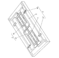
従来この種のセンシング装置は、図5に示すような圧電材料を有する振動子1を、例えば自動車の進行方向にその長手方向が一致するよう配置し、前記振動子1の一端1Aを固定すると共に他端1Bに錘2を配置し、前記振動子1の一部に駆動振動を与える駆動電極と振動数を検出する検出電極とを設ける構成としていた。そして、例えば自動車が加速し、加速度がこのセンシング装置に加わると、それに伴い前記振動子1が伸縮し、前記検出電極により検出される周波数が変化する。この変化を加速度としてあるいは傾斜角として算出する構成としていた。
Conventionally, in this type of sensing device, a
なお、この出願に関する先行技術文献情報としては、例えば、特許文献1が知られている。
このような従来のセンシング装置では、小型化が難しいことが問題となってしまっていた。 In such a conventional sensing device, it has been a problem that miniaturization is difficult.
すなわち、上記従来の構成においては、センシング信号を周波数として検出していたため、これを電圧に変換するF/V変換回路が必要不可欠となり、その結果として小型化が難しくなってしまっていた。 That is, in the above-described conventional configuration, since the sensing signal is detected as a frequency, an F / V conversion circuit that converts the sensing signal into a voltage becomes indispensable, and as a result, downsizing becomes difficult.
そこで本発明は、センシング装置の小型化を実現することを目的とする。 Therefore, an object of the present invention is to realize downsizing of the sensing device.
そして、この目的を達成するために本発明は、圧電材料を有する第1の振動子と、前記第1の振動子の一端にその一端が機械的結合された圧電材料を有する第2の振動子と、前記第1、第2の振動子間に設けられた錘と、前記第1、第2の振動子の内少なくとも一方に駆動振動を与える駆動電極と、前記第1、第2の振動子の内少なくとも一方の振幅を検出する検出電極とを備え、前記第1、第2の振動子が縮退状態となっている範囲で機械量を検出するセンシング装置としたものである。 In order to achieve this object, the present invention provides a first vibrator having a piezoelectric material, and a second vibrator having a piezoelectric material having one end mechanically coupled to one end of the first vibrator. A weight provided between the first and second vibrators, a drive electrode for applying drive vibration to at least one of the first and second vibrators, and the first and second vibrators And a detection electrode that detects the amplitude of at least one of the first and second transducers, and a sensing device that detects a mechanical quantity within a range where the first and second vibrators are in a degenerated state.
この構成により、周波数ではなく前記振動子の振幅をセンシング信号として検出することができるため、F/V変換回路が不要となり、その結果として小型化を実現することができるのである。 With this configuration, not the frequency but the amplitude of the vibrator can be detected as a sensing signal, so that an F / V conversion circuit is not required, and as a result, downsizing can be realized.
(実施の形態1)
以下、本発明の実施の形態1におけるセンシング装置について図面を参照しながら説明する。
(Embodiment 1)
Hereinafter, the sensing device according to
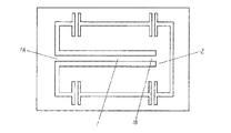
図1に示すごとく、圧電材料を有する第1の振動子11と、前記第1の振動子11の一端にその一端が機械的結合された圧電材料を有する第2の振動子12と、前記第1、第2の振動子11、12間に設けられた錘13と、前記第1、第2の振動子11、12の内少なくとも一方に駆動振動を与える駆動電極14と、前記第1、第2の振動子11、12の内少なくとも一方の振幅を検出する検出電極15とを備えている。 As shown in FIG. 1, a first vibrator 11 having a piezoelectric material, a second vibrator 12 having a piezoelectric material having one end mechanically coupled to one end of the first vibrator 11, and the first vibrator A weight 13 provided between the first and second vibrators 11 and 12, a drive electrode 14 for applying drive vibration to at least one of the first and second vibrators 11 and 12, and the first and second vibrators. And a detection electrode 15 for detecting the amplitude of at least one of the two vibrators 11 and 12.
具体的には、前記検出電極15が第1の検出電極15Aと第2の検出電極15Bからなり、前記第1の検出電極15Aが前記第1の振動子11の他端に設けられ、前記第2の検出電極15Bが前記第2の振動子12の他端に設けられ、前記駆動電極14が前記第1、第2の振動子11、12の一端にそれぞれ第1の駆動電極14A、第2の駆動電極14Bとして設けられた構成としている。そして、前記第1、第2の振動子11、12が縮退状態となっている範囲で加速度などの機械量を検出する。
Specifically, the detection electrode 15 includes a
ここで、縮退状態について説明する。 Here, the degenerated state will be described.
まず、図1における前記第1の振動子11の全長をx、前記第2の振動子12の全長を(1−x)とし、前記第1、第2の振動子11、12の全長が可変状態にあるとする。そして、前記第1の振動子11の他端と前記第2の振動子12の他端はそれぞれ固定されており、例えば、自動車にこの2つの振動子の長手方向が前記自動車の進行方向と一致するよう配置されているとする。ここで、図1における矢印方向に加速度が加わったとすると、慣性の法則により、前記錘13が前記第2の振動子12側に移動するため、その周波数が変化する。 First, the total length of the first vibrator 11 in FIG. 1 is x, the total length of the second vibrator 12 is (1-x), and the total length of the first and second vibrators 11 and 12 is variable. Suppose you are in a state. The other end of the first vibrator 11 and the other end of the second vibrator 12 are fixed. For example, in a car, the longitudinal direction of the two vibrators coincides with the traveling direction of the car. Suppose that they are arranged. Here, if acceleration is applied in the direction of the arrow in FIG. 1, the weight 13 moves toward the second vibrator 12 according to the law of inertia, so that the frequency changes.
その周波数の変化を示すのが図2である。図2は横軸に前記第1の振動子11の全長であるxをとっており、縦軸に周波数をとっている。前記第1の振動子11が前記第2の振動子12と機械的結合関係に無い場合、前記第1の振動子11の周波数は直線Aに示すごとく前記振動子11の全長xが大きくなるに従って低くなる。一方、前記第2の振動子12は、前記第1の振動子11の全長xが大きくなるにしたがってその全長(1−x)が小さくなるため、前記第2の振動子12の周波数は図2の直線Bに示すごとく、前記第1の振動子11の全長xが大きくなるに従って高くなる。 FIG. 2 shows the change in the frequency. In FIG. 2, the horizontal axis represents x which is the total length of the first vibrator 11, and the vertical axis represents frequency. When the first vibrator 11 is not mechanically coupled to the second vibrator 12, the frequency of the first vibrator 11 increases as the total length x of the vibrator 11 increases as shown by the straight line A. Lower. On the other hand, since the total length (1-x) of the second vibrator 12 decreases as the total length x of the first vibrator 11 increases, the frequency of the second vibrator 12 is as shown in FIG. As shown by the straight line B, the total length x of the first vibrator 11 increases as the length increases.
ここで、前記第1、第2の振動子11、12が機械的結合された場合、図2に示した直線Aは曲線Cへ、直線Bは曲線Dへと変化する。そして、前記第1の振動子11の全長xと前記第2の振動子12の全長(1−x)とが近接するある範囲で、前記第1の振動子11の周波数と前記第2の振動子12の周波数とが一定となる。これが縮退状態である。 Here, when the first and second vibrators 11 and 12 are mechanically coupled, the straight line A and the straight line B shown in FIG. Then, the frequency of the first vibrator 11 and the second vibration are within a certain range in which the full length x of the first vibrator 11 and the full length (1-x) of the second vibrator 12 are close to each other. The frequency of the child 12 is constant. This is a degenerate state.
なお、この縮退状態については永井健三、今野正共著の「電気機械振動子とその応用」の261頁を参照されたい。 As for this degenerate state, refer to page 261 of “Electromechanical vibrator and its application” written by Kenzo Nagai and Shoji Imano.
このような縮退状態においては、図2に示すごとく周波数が一定となる一方で、前記第1、第2の振動子11、12の振幅状態に変化が起こる。本実施の形態のように、図1に示す矢印方向に加速度が加わった場合には、前記第1の振動子11の全長xが短くなると共にその振幅が小さくなり、前記第2の振動子12の全長(1−x)が長くなると共にその振幅が大きくなる。この変化を前記第1、第2の検出電極15A、15Bにより検出し、それを加速度として算出するのである。
In such a degenerate state, the frequency is constant as shown in FIG. 2, while the amplitude states of the first and second vibrators 11 and 12 change. When acceleration is applied in the direction of the arrow shown in FIG. 1 as in the present embodiment, the total length x of the first vibrator 11 becomes shorter and the amplitude thereof becomes smaller, and the second vibrator 12 is reduced. As the total length (1-x) of the plate increases, its amplitude increases. This change is detected by the first and
なお、加速度の算出方法としては、図3に示すごとく、前記第1の振動子11に対応する第1の振幅を前記第1の検出電極15Aから検出すると共に前記第2の振動子12に対応する第2の振幅を前記第2の検出電極15Bから検出し、これら第1、第2の振幅の差を差動増幅器16で演算して出力する方法であれば、より高精度な加速度の算出を可能とすることができる。
As shown in FIG. 3, the acceleration is calculated by detecting the first amplitude corresponding to the first vibrator 11 from the
なお、本実施の形態においては、前記第1の検出電極15Aが前記第1の振動子11の他端に設けられ、前記第2の検出電極15Bが前記第2の振動子12の他端に設けられ、前記駆動電極14が前記第1、第2の振動子11、12の一端に第1の駆動電極14A、第2の駆動電極14Bとして設けられた構成として説明したが、図4に示すごとく、前記第1の検出電極15Aが前記第1の振動子11の一端に設けられ、前記第2の検出電極15Bが前記第2の振動子12の一端に設けられ、前記第1の駆動電極14Aが前記第1の振動子11の他端に設けられ、前記第2の駆動電極14Bが前記第2の振動子12の他端に設けられた構成としても構わない。
In the present embodiment, the
なお、第1、第2の振動子11、12は、圧電材料そのものでもよく、また、金属、セラミック等の振動部材と圧電材料とを一体化させたものでも構わない。 Note that the first and second vibrators 11 and 12 may be piezoelectric materials themselves, or may be a material in which a vibrating member such as metal or ceramic and a piezoelectric material are integrated.
なお、本実施の形態においては加速度センサを例に挙げ説明したが、傾斜角センサとしても応用可能である。具体的には、図1の第1の振動子11が斜面における高位置に存在し、第2の振動子12が低位置に存在する場合、前記錘13が前記第2の振動子12側に移動する。そして、上述した原理により前記第1、第2の振動子11、12の振幅変化から傾斜角としてその値を算出することが可能である。 In the present embodiment, the acceleration sensor has been described as an example, but the present invention can also be applied as a tilt angle sensor. Specifically, when the first vibrator 11 in FIG. 1 is at a high position on the slope and the second vibrator 12 is at a low position, the weight 13 is located on the second vibrator 12 side. Moving. Then, it is possible to calculate the value as the tilt angle from the amplitude change of the first and second vibrators 11 and 12 according to the principle described above.
なお、自動車にこのセンシング装置を搭載し、前記自動車の進行方向に当該センシング装置の長手方向が一致するよう配置した場合において、前記自動車が坂道を走った場合には、加速度情報と傾斜角情報とが混在した形で振幅変化に現れるわけであるが、前記自動車が発進してから停止するまでの加速度は積分すると0となるため、その値を相殺することにより、傾斜角のみを抽出して算出することも可能である。 In addition, when this sensing device is mounted on an automobile and arranged such that the longitudinal direction of the sensing device coincides with the traveling direction of the automobile, when the automobile runs on a slope, acceleration information and inclination angle information However, since the acceleration from the start of the vehicle to the stop is 0 when integrated, only the inclination angle is extracted by offsetting the value. It is also possible to do.
なお、自動車の走行距離を測定する走行センサと組合せば、上述のごとく算出した傾斜角の正弦を取った値に前記走行距離を乗算することにより、高度計としての応用も可能である。 When combined with a travel sensor that measures the travel distance of an automobile, it can be applied as an altimeter by multiplying the travel distance by a value obtained by taking the sine of the inclination angle calculated as described above.
本発明のセンシング装置は、小型化を実現することができるという効果を有し、自動車やカーナビゲーション装置等において有用である。 The sensing device of the present invention has an effect that it can be miniaturized, and is useful in automobiles, car navigation devices, and the like.
11 第1の振動子
12 第2の振動子
13 錘
14 駆動電極
15 検出電極
11 First vibrator 12 Second vibrator 13 Weight 14 Drive electrode 15 Detection electrode
Claims (5)
前記第1の振動子の一端にその一端が機械的結合された
圧電材料を有する第2の振動子と、
前記第1、第2の振動子間に設けられた錘と、
前記第1、第2の振動子の内少なくとも一方に駆動振動を与える駆動電極と、
前記第1、第2の振動子の内少なくとも一方の振幅を検出する検出電極とを備え、
前記第1、第2の振動子が縮退状態となっている範囲で機械量を検出する
センシング装置。 A first vibrator having a piezoelectric material;
A second vibrator having a piezoelectric material having one end mechanically coupled to one end of the first vibrator;
A weight provided between the first and second vibrators;
A drive electrode for applying drive vibration to at least one of the first and second vibrators;
A detection electrode for detecting an amplitude of at least one of the first and second vibrators,
A sensing device that detects a mechanical quantity in a range where the first and second vibrators are in a degenerated state.
前記第1の検出電極が前記第1の振動子の他端に設けられ、
前記第2の検出電極が前記第2の振動子の他端に設けられ、
前記駆動電極が前記第1、第2の振動子の内の少なくとも一方の一端に設けられた
請求項1に記載のセンシング装置。 The detection electrode comprises a first detection electrode and a second detection electrode;
The first detection electrode is provided at the other end of the first vibrator;
The second detection electrode is provided at the other end of the second vibrator;
The sensing device according to claim 1, wherein the drive electrode is provided at one end of at least one of the first and second vibrators.
前記第2の振動子に対応する第2の振幅とからなり、
前記第1の検出電極から前記第1の振幅を検出し、
前記第2の検出電極から前記第2の振幅を検出し、
前記第1、第2の振幅の差を演算して出力する
請求項2に記載のセンシング装置。 The amplitude includes a first amplitude corresponding to the first vibrator and a second amplitude corresponding to the second vibrator;
Detecting the first amplitude from the first detection electrode;
Detecting the second amplitude from the second detection electrode;
The sensing device according to claim 2, wherein the difference between the first and second amplitudes is calculated and output.
前記第1の検出電極が前記第1の振動子の一端に設けられ、
前記第2の検出電極が前記第2の振動子の一端に設けられ、
前記駆動電極が第1の駆動電極と第2の駆動電極とからなり、
前記第1の駆動電極が前記第1の振動子の他端に設けられ、
前記第2の駆動電極が前記第2の振動子の他端に設けられた
請求項1に記載のセンシング装置。 The detection electrode comprises a first detection electrode and a second detection electrode;
The first detection electrode is provided at one end of the first vibrator;
The second detection electrode is provided at one end of the second vibrator;
The drive electrode comprises a first drive electrode and a second drive electrode;
The first drive electrode is provided at the other end of the first vibrator;
The sensing device according to claim 1, wherein the second drive electrode is provided at the other end of the second vibrator.
前記第2の振動子に対応する第2の振幅とからなり、
前記第1の検出電極から前記第1の振幅を検出し、
前記第2の検出電極から前記第2の振幅を検出し、
前記第1、第2の振幅の差を演算して出力する
請求項4に記載のセンシング装置。 The amplitude includes a first amplitude corresponding to the first vibrator and a second amplitude corresponding to the second vibrator;
Detecting the first amplitude from the first detection electrode;
Detecting the second amplitude from the second detection electrode;
The sensing device according to claim 4, wherein the difference between the first and second amplitudes is calculated and output.
Priority Applications (1)
| Application Number | Priority Date | Filing Date | Title |
|---|---|---|---|
| JP2008174138A JP4998388B2 (en) | 2008-07-03 | 2008-07-03 | Sensing device |
Applications Claiming Priority (1)
| Application Number | Priority Date | Filing Date | Title |
|---|---|---|---|
| JP2008174138A JP4998388B2 (en) | 2008-07-03 | 2008-07-03 | Sensing device |
Publications (2)
| Publication Number | Publication Date |
|---|---|
| JP2010014510A true JP2010014510A (en) | 2010-01-21 |
| JP4998388B2 JP4998388B2 (en) | 2012-08-15 |
Family
ID=41700755
Family Applications (1)
| Application Number | Title | Priority Date | Filing Date |
|---|---|---|---|
| JP2008174138A Expired - Fee Related JP4998388B2 (en) | 2008-07-03 | 2008-07-03 | Sensing device |
Country Status (1)
| Country | Link |
|---|---|
| JP (1) | JP4998388B2 (en) |
Citations (5)
| Publication number | Priority date | Publication date | Assignee | Title |
|---|---|---|---|---|
| JPH04361165A (en) * | 1991-06-07 | 1992-12-14 | Japan Aviation Electron Ind Ltd | Oscillator type accelerometer |
| JP2000206141A (en) * | 1999-01-20 | 2000-07-28 | Miyota Kk | Momentum sensor |
| JP2001133476A (en) * | 1999-11-01 | 2001-05-18 | Matsushita Electric Ind Co Ltd | Acceleration sensor |
| JP2005249446A (en) * | 2004-03-02 | 2005-09-15 | Matsushita Electric Ind Co Ltd | Vibration piezoelectric acceleration sensor |
| JP2007163200A (en) * | 2005-12-12 | 2007-06-28 | Epson Toyocom Corp | Vibrating reed and angular velocity sensor |
-
2008
- 2008-07-03 JP JP2008174138A patent/JP4998388B2/en not_active Expired - Fee Related
Patent Citations (5)
| Publication number | Priority date | Publication date | Assignee | Title |
|---|---|---|---|---|
| JPH04361165A (en) * | 1991-06-07 | 1992-12-14 | Japan Aviation Electron Ind Ltd | Oscillator type accelerometer |
| JP2000206141A (en) * | 1999-01-20 | 2000-07-28 | Miyota Kk | Momentum sensor |
| JP2001133476A (en) * | 1999-11-01 | 2001-05-18 | Matsushita Electric Ind Co Ltd | Acceleration sensor |
| JP2005249446A (en) * | 2004-03-02 | 2005-09-15 | Matsushita Electric Ind Co Ltd | Vibration piezoelectric acceleration sensor |
| JP2007163200A (en) * | 2005-12-12 | 2007-06-28 | Epson Toyocom Corp | Vibrating reed and angular velocity sensor |
Also Published As
| Publication number | Publication date |
|---|---|
| JP4998388B2 (en) | 2012-08-15 |
Similar Documents
| Publication | Publication Date | Title |
|---|---|---|
| JP6604200B2 (en) | Accelerometer, measurement system, and measurement device | |
| JP5301767B2 (en) | Inertial sensor | |
| JP4899781B2 (en) | Capacitive mechanical quantity detector | |
| JP5458462B2 (en) | Vibration type inertial force detection sensor | |
| JPWO2008032415A1 (en) | Angular velocity sensor | |
| EP0568978B1 (en) | Gyro-compass | |
| JP2007107909A5 (en) | ||
| JP4668739B2 (en) | Vibrating gyro | |
| JPH10221083A (en) | Vibration-type gyro apparatus | |
| JP4911690B2 (en) | Vibrating gyro vibrator | |
| WO2015162888A1 (en) | Angular speed sensor | |
| JP5187836B2 (en) | Sensor sensitivity adjusting means and sensor manufacturing method | |
| JP2005172836A (en) | Sensor having symmetric limitation of signal | |
| WO2018003692A1 (en) | Physical quantity sensor | |
| JP4998388B2 (en) | Sensing device | |
| JP4687085B2 (en) | Compound sensor | |
| JP2009047649A (en) | Tuning-fork vibrating type sensor, mechanical quantity detector, and mechanical quantity detection method | |
| JP2006162314A (en) | Compound sensor | |
| JP2006226802A (en) | Compound sensor | |
| JP2009063369A (en) | Acceleration sensor element and acceleration sensor | |
| JP4935069B2 (en) | Angular velocity sensor | |
| WO2019017277A1 (en) | Vibration type angular velocity sensor | |
| JP2006162315A (en) | Compound sensor | |
| JP2005308530A (en) | Angular speed/acceleration composite sensor | |
| JP6604158B2 (en) | Vibration type angular velocity sensor |
Legal Events
| Date | Code | Title | Description |
|---|---|---|---|
| A621 | Written request for application examination |
Free format text: JAPANESE INTERMEDIATE CODE: A621 Effective date: 20110620 |
|
| RD01 | Notification of change of attorney |
Free format text: JAPANESE INTERMEDIATE CODE: A7421 Effective date: 20110713 |
|
| TRDD | Decision of grant or rejection written | ||
| A01 | Written decision to grant a patent or to grant a registration (utility model) |
Free format text: JAPANESE INTERMEDIATE CODE: A01 Effective date: 20120417 |
|
| A01 | Written decision to grant a patent or to grant a registration (utility model) |
Free format text: JAPANESE INTERMEDIATE CODE: A01 |
|
| A977 | Report on retrieval |
Free format text: JAPANESE INTERMEDIATE CODE: A971007 Effective date: 20120418 |
|
| A61 | First payment of annual fees (during grant procedure) |
Free format text: JAPANESE INTERMEDIATE CODE: A61 Effective date: 20120430 |
|
| FPAY | Renewal fee payment (event date is renewal date of database) |
Free format text: PAYMENT UNTIL: 20150525 Year of fee payment: 3 |
|
| LAPS | Cancellation because of no payment of annual fees |