JP2010014491A - Offshore monitoring system method - Google Patents
Offshore monitoring system method Download PDFInfo
- Publication number
- JP2010014491A JP2010014491A JP2008173740A JP2008173740A JP2010014491A JP 2010014491 A JP2010014491 A JP 2010014491A JP 2008173740 A JP2008173740 A JP 2008173740A JP 2008173740 A JP2008173740 A JP 2008173740A JP 2010014491 A JP2010014491 A JP 2010014491A
- Authority
- JP
- Japan
- Prior art keywords
- measurement object
- image data
- color
- offshore
- time
- Prior art date
- Legal status (The legal status is an assumption and is not a legal conclusion. Google has not performed a legal analysis and makes no representation as to the accuracy of the status listed.)
- Granted
Links
Images


Abstract
Description
本発明は、洋上浮遊物を監視する洋上監視システムおよび方法に関する。 The present invention relates to an offshore monitoring system and method for monitoring offshore floating objects.
地球温暖化による流氷の溶解や有害プランクトンの大量発生、船舶事故に伴う油の流出や海ゴミの漂流など、洋上の浮遊物を観測する必要性は近年増加しており、浮遊物の位置を高い精度で測定することが求められている。対象物の位置を測定する装置として、例えば特許文献1及び特許文献2に開示された構成が知られている。
In recent years, the need for observation of floating substances on the ocean, such as melting of drift ice due to global warming, large-scale occurrence of harmful plankton, oil spills and marine litter associated with ship accidents, has increased in recent years. It is required to measure with accuracy. As an apparatus for measuring the position of an object, for example, configurations disclosed in
特許文献1の装置は、撮像装置の測位データ及び傾斜データを含む複数の所定ラインの画像データから合成連続モザイク画像を高度0mに投影し、マッチング演算により浮標の軌跡を算出している。
The device of
特許文献2の装置は、対象物に対して相対移動する撮像装置により対象物を時系列的に撮影し、得られた一連の撮影画像から特徴点を抽出する。ついで、各特徴点の追跡処理を行い、対応特徴点が付された一連の撮影画像からステレオ画像を選択して、標定及び3次元計測を行う。そして、3次元計測により算出された対応特徴点の誤差範囲に基づいて各対応特徴点の適否を判定し、不適当と判定された対応特徴点を除外した上で、標定及び3次元計測を再度行うことにより、計測精度の向上を図っている。
ところが、上記特許文献1に開示された装置は、マッチング演算を行うために、撮影された瞬間における、対象物に対する撮像装置の位置及び撮影角度を正確に把握する必要があるため、風などによる振動の影響を受けやすい撮影飛行においては撮像装置の位置と角度の測定精度の向上に大きな制約があった。たとえば、防振能を備えた高精度の測定機器を使用する場合には、設備が高価なだけでなく、重量が過大になる。そのため搭載重量に限界がある船舶曳航型の気球などからの撮影は極めて困難であり、観測現場に近い船舶からの定量的な監視技術は需要が高まっているにも関わらず、実用化されていない。
However, since the apparatus disclosed in
また、上記特許文献2に開示された装置は、ステレオ画像による補正のため、安定した特徴点を必要とする。しかし、撮影場所が洋上である場合には、ほとんどの特徴点が風や波、潮の流れなどの不確定要素の影響を受け短時間に大きく移動し、確度の高い特徴点を得ることが困難なため、計測精度の向上に限界がある。 Further, the apparatus disclosed in Patent Document 2 requires stable feature points for correction using a stereo image. However, when the shooting location is offshore, most of the feature points are affected by uncertain factors such as wind, waves, and tide flow, and move greatly in a short time, making it difficult to obtain highly accurate feature points. Therefore, there is a limit to the improvement of measurement accuracy.
そこで、本発明は、安価で軽量な構成により監視精度を高めることができる洋上監視システムおよび方法の提供を目的とする。 Therefore, an object of the present invention is to provide an offshore monitoring system and method capable of increasing the monitoring accuracy with an inexpensive and lightweight configuration.
本発明の前記目的は、洋上の測定対象物を撮像して時系列の画像データを生成する撮像装置と、前記画像データを解析して測定対象物の位置情報を生成する解析装置とを備え、前記解析装置は、各時刻における測定対象物の座標値を算出し、所定時間内の前記座標値の中央値または平均値から、測定対象物の位置情報を求める洋上監視システムにより達成される。 The object of the present invention includes an imaging device that images a measurement object on the ocean and generates time-series image data, and an analysis device that analyzes the image data and generates position information of the measurement object. The analysis device is achieved by an offshore monitoring system that calculates coordinate values of a measurement object at each time and obtains position information of the measurement object from a median value or an average value of the coordinate values within a predetermined time.
また、本発明の前記目的は、洋上の測定対象物を撮像して時系列の画像データを生成する撮像ステップと、前記画像データを解析して測定対象物の位置情報を生成する解析ステップとを備え、前記解析ステップは、各時刻における測定対象物の座標値を算出し、所定時間内の前記座標値の中央値または平均値から、測定対象物の位置情報を求める洋上監視方法により達成される。 In addition, the object of the present invention is to provide an imaging step of imaging a measurement object on the ocean to generate time-series image data, and an analysis step of analyzing the image data to generate position information of the measurement object. The analysis step is achieved by an offshore monitoring method that calculates a coordinate value of the measurement object at each time and obtains position information of the measurement object from a median value or an average value of the coordinate values within a predetermined time. .
本発明によれば、安価で軽量な構成により監視精度を高め、船舶観測を可能にする洋上監視システムおよび方法を提供することができる。 According to the present invention, it is possible to provide an offshore monitoring system and method capable of improving ship monitoring accuracy and enabling ship observation with an inexpensive and lightweight configuration.
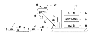
以下、本発明の実施の形態について、添付図面を参照して説明する。図1は、本発明の一実施形態に係る洋上監視システムの概略構成図である。図1に示すように、洋上監視システム1は、複数の浮標体10と、撮像装置20と、解析装置30とを備えている。
Hereinafter, embodiments of the present invention will be described with reference to the accompanying drawings. FIG. 1 is a schematic configuration diagram of an offshore monitoring system according to an embodiment of the present invention. As shown in FIG. 1, the
浮標体10は、洋上を浮遊可能なブイなどからなり、上面中央にGPSロガーが設置されている。このGPSロガーは、GPS衛星からのGPS信号を受信する受信部12と、時系列のGPS信号を記録する記録部14とを備えている。GPS信号は、例えば、運輸多目的衛星用衛星航法補強システム(MSAS)を使用して、安価及び軽量な非ディファレンシャルGPSにおいても比較的精度の高い測定が可能となる。
各浮標体10の表面には、洋上Sに浮遊した状態で視覚により判別可能な色がそれぞれ付されており、浮標体10の数が多いほど測定精度を高めることができる。本実施形態においては、海面色との色差が大きい桃、緑、赤、黄、橙の各色からなる5種類の浮標体10が用意されている。各浮標体10は、後述するように、測定対象物Mの近傍に投下される。この場合、測定対象物の色との色差の大きい色の浮標体を用いることが好ましい。GPSを搭載した洋上船28の一部分を浮標体の一つとして用いても良い。また浮標体は、必ずしも単一色である必要はない。ただし、その場合は、浮標体の識別条件に隣接情報を追加する必要がある。
The
The surface of each
撮像装置20は、撮像により画像データを取得する撮像部22と、取得した画像データを記録する画像記録部24とを備えており、これら撮像部22及び画像記録部24がバルーン船21に搭載されて、空中から撮像可能に構成されている。バルーン船21は、係留索23を介して洋上船28により曳航可能とされており、撮像部22の水平方向の撮影位置は、洋上船28の移動により制御することができ、鉛直方向の撮影位置は、係留索23の巻き取り又は巻き戻しにより調整可能である。また、洋上船28は、撮像部22を遠隔操作するための無線送信部27を有しており、バルーン船21に設置した無線受信部25を介して撮像方向を調整可能である。
The
解析装置30は、浮標体10及び撮像装置20にそれぞれ記録された時系列のGPS信号及び画像データを入力する入力部32と、入力されたデータの解析を行う解析処理部34と、解析結果を画面表示などにより出力する出力部36とを備えており、例えば一般的なパーソナルコンピュータから構成することができる。解析装置30は、洋上船28に搭載すれば観測場所での解析も可能であるが、撮影後に他の場所で解析することも可能である。
The
次に、上記の構成を備える洋上監視システム1を用いて洋上監視を行う方法を説明する。まず、色が異なる複数の浮標体10を、洋上船に搭載するなどして海面を浮遊する測定対象物の近傍まで移動させ、洋上に投下する。測定対象物は、特に限定されるものではないが、例えば、洋上漂流ゴミ、流出油、プランクトン、流氷などを挙げることができる。洋上を浮遊する各浮標体10は、GPS衛星からGPS信号を受信して、各時刻における緯度情報及び経度情報を記録部14に記録する。こうして、基準点となる各浮標体10の位置を把握することができる。浮標体10は、受信するGPS信号を解析装置30に送信するための無線送信部を備えていてもよく、これによって、解析装置30が各浮標体10の位置をリアルタイムに把握することができる。
Next, a method for performing offshore monitoring using the
次に、撮像装置20を手動で遠隔操作して、撮像領域内に各浮標体10および測定対象物が常に存在するように撮像する。得られた時系列の画像データは、記録部24に格納される。画像データについても、解析装置30にリアルタイムに送信することができる。また、低解像度の画像データのみを洋上船28に無線送信して撮像部22の傾斜角度を制御すると共に、高解像度の画像データについては記録部24に記録するようにしてもよい。
Next, the
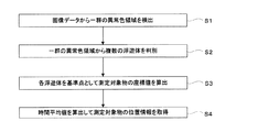
解析装置30は、所定時間内において浮標体10及び撮像装置20からそれぞれ入力されたGPS信号及び画像データに基づき、測定対象物の座標値を求める。この手順を、図2に示すフローチャートを適宜参照しながら説明する。
The
まず、画像データから一群の異常色領域を検出する(ステップS1)。例えば、所定の色空間において、小領域単位で色座標の中央値から画像データにおける海領域を抽出した後、この海領域に含まれる異常色領域を検出する。用いる色空間は、人間が知覚する色差と色空間内ユークリッド距離とが一致するようなCIELUVやCIELABなどの均等色空間であることが好ましい。ただし、人間の知覚しにくい微小な色差の浮標体及び測定対象物を検出したい場合は、それに適した不均等な色空間を用いても良い。 First, a group of abnormal color regions are detected from image data (step S1). For example, in a predetermined color space, after extracting a sea area in the image data from the median value of color coordinates in small area units, an abnormal color area included in the sea area is detected. The color space to be used is preferably a uniform color space such as CIELV or CIELAB in which the color difference perceived by humans matches the Euclidean distance in the color space. However, when it is desired to detect a buoyant and a measurement object having a minute color difference that are difficult for humans to perceive, an uneven color space suitable for the buoyant may be used.
画像データに陸領域または船舶など測定対象物以外の不要な異常色は、解析時間を短縮するためにも、含まれない方が好ましい。含まれる場合には、例えば前記小領域の色空間の中央値から明らかに海領域ではない領域と、それらの近傍である海と陸の境界領域の分散値の大きい海岸線近傍を陸域として抽出することにより、陸域の緑、岸壁、雲、空、観測船、水面に映った陸上物等を異常色領域から除外することができる。エッジ検出で境界を検出しても良いし、経験的に明らかに海色ではない色域の画素を除外するようなより簡単な方法でも良い。こうして抽出された海領域から海との色差の大きい一群の異常色領域を検出する。検出には、例えば、前記CIELUV上の輝度Lと色彩UVのマハラノビス距離が所定値以上の画素を抽出して行うことができる。 It is preferable that unnecessary abnormal colors other than the measurement object such as a land area or a ship are not included in the image data in order to shorten the analysis time. If included, for example, a region that is clearly not a sea region from the median value of the color space of the small region, and a coastline neighborhood with a large variance value of the boundary region between the sea and land that are in the vicinity are extracted as a land region. Thus, land green, quay, clouds, sky, observation ship, land objects reflected on the water surface, etc. can be excluded from the abnormal color area. The boundary may be detected by edge detection, or a simpler method such as excluding pixels in a color gamut that is clearly not a sea color empirically may be used. A group of abnormal color areas having a large color difference from the sea is detected from the sea areas thus extracted. The detection can be performed, for example, by extracting pixels whose Mahalanobis distance between the luminance L on the CIELV and the color UV is a predetermined value or more.
一群の異常色領域を複数の画素の塊として認識し、個々の塊の持つ画像上の色と画素座標の代表値を算出する。代表値の算出には、例えば、色空間などのクラスタリング手法として公知のMean Shift法を好ましく使用することができる。Mean Shift法については、例えば、次の文献が参考になる。Dorin Comaniciu and Peter Meer.Mean shift:A robust approach toward feature space analysis.IEEE Transactions on Pattern Analysis and Machine Intelligence,Vol.24, No.5, pp.603-619, 2002
Mean Shift法とは、ある座標系において複数の正規分布で分散する分類対象点を局所平均の座標に逐次移動させ、クラスター中心に収束させる方法である。どの程度の近傍を類似しているとみなすかの判定基準を制御する窓パラメータを与えるだけで、予め分類数を設定する必要がない簡易な方法である。例えば、本実施形態においては、色彩座標(U,V)と画素座標(x,y)の二つの座標系を一括処理する四次元座標に対してMean Shift法を適用し、判定された各塊の色座標の重心、画素座標の重心、そして分類画素数により、海と異なる任意の色を持つ、任意の数の洋上漂流物の、画像上の色、位置、大きさを一括して算出できる。窓パラメータについては、色座標と画素座標のそれぞれに設定する。各浮標体または測定対象物の色のばらつきと画像上の大きさに応じて設定することが好ましい。ここで輝度Lについては、経験的に必ずしも正規分布に従わなかったことから判定基準には用いないが、色彩座標(U,V)と画素座標(x,y)を基準に分類された画素の平均輝度を、画素の塊毎に算出する。こうして検出された一群の異常色領域は、なんらかの洋上漂流物に対応しており、これら異常色領域の中に各浮標体が存在する。
A group of abnormal color regions is recognized as a plurality of pixel clusters, and the representative values of the color and pixel coordinates on the image of each cluster are calculated. For calculating the representative value, for example, a well-known Mean Shift method can be preferably used as a clustering method such as a color space. For the Mean Shift method, for example, the following document is helpful. Dorin Comaniciu and Peter Meer.Mean shift: A robust approach toward feature space analysis.IEEE Transactions on Pattern Analysis and Machine Intelligence, Vol.24, No.5, pp.603-619, 2002
The Mean Shift method is a method in which classification target points dispersed in a plurality of normal distributions in a certain coordinate system are sequentially moved to local average coordinates and converged to the cluster center. This is a simple method in which it is not necessary to set the number of classifications in advance simply by giving a window parameter that controls the criterion for determining how close the neighborhood is to be similar. For example, in the present embodiment, the Mean Shift method is applied to the four-dimensional coordinates that collectively process the two coordinate systems of the color coordinates (U, V) and the pixel coordinates (x, y), and each determined block is determined. The color, position, and size on the image of any number of offshore drifting objects that have any color different from the ocean can be calculated at once by the center of gravity of the color coordinates, the center of gravity of the pixel coordinates, and the number of classified pixels. . The window parameter is set for each of color coordinates and pixel coordinates. It is preferable to set according to the color variation of each buoyant or measurement object and the size on the image. Here, the luminance L is not used as a criterion for judgment because it does not always follow the normal distribution from experience, but the luminance of the pixels classified based on the color coordinates (U, V) and the pixel coordinates (x, y) is not used. The average luminance is calculated for each pixel block. The group of abnormal color areas detected in this way corresponds to some offshore drifting objects, and each buoyant body exists in these abnormal color areas.
次に、一群の異常色領域から複数の浮標体を判別する(ステップS2)。検出された異常色領域は、白波や海面反射などによって浮標体以外のノイズを含むおそれがあるため、浮標体のみを抽出する必要がある。そこで、例えば浮標体が5つの場合、所定の色空間において、5つの異常色領域の組み合わせによる5つの色重心を検出し、予め格納された各浮標体の色情報と比較して色差を求め、この色差の合計が最小となる異常色領域の組み合わせを決定する。こうして、画像データにおける5つの基準点を特定することができる。このように抽出された色重心及び画素重心が、撮影画像中の各浮標体の色座標C(L,U,V)と画素座標(xi,yi)を示すものとなる(i=1〜L、ただし本実施例ではL=5)。 Next, a plurality of buoys are determined from a group of abnormal color regions (step S2). Since the detected abnormal color area may contain noise other than the buoyant body due to white waves or sea surface reflection, it is necessary to extract only the buoyant body. Therefore, for example, when there are five buoys, five color centroids are detected by combining five abnormal color regions in a predetermined color space, and the color difference is obtained by comparing with color information stored in advance for each buoy. A combination of abnormal color regions that minimizes the sum of the color differences is determined. In this way, five reference points in the image data can be specified. The color centroid and pixel centroid extracted in this way indicate the color coordinates C (L, U, V) and pixel coordinates (xi, yi) of each buoyant in the captured image (i = 1 to L). However, in this embodiment, L = 5).
絶対座標系(例えばWGS-84座標系)における、前記浮標体の座標値(Xi,Yi)及び測定対象物の座標値P(XP,YP)は、陸上物とは異なり、波、風、潮の流れなどの影響を受けて、時間の経過と共に移動する。しかしながら前記浮標体の座標値(Xi,Yi)は、複数の浮標体のGPS信号の緯度及び経度により時系列的に把握することができる。また本実施例では、前記浮標体及び測定対象物が様々な位置及び角度より撮影されるため、撮像系においても、浮標体の画素座標(xi,yi)及び測定対象物の画素座標P(xp,yp)は、時系列的に極めて不連続である。そこで、GPS信号により求めた座標値(Xi,Yi)とステップS2で求めた画素座標(xi,yi)の関係を基準として、以下に説明する射影変換によりステップS1で抽出された任意の測定対象物の座標値G(XG,YG)を算出する(ステップS3)。 In the absolute coordinate system (for example, WGS-84 coordinate system), the coordinate value (Xi, Yi) of the buoyant and the coordinate value P (XP, YP) of the object to be measured are different from those of land objects. It moves with the passage of time under the influence of the flow of However, the coordinate values (Xi, Yi) of the buoy can be grasped in a time series from the latitude and longitude of GPS signals of a plurality of buoys. In this embodiment, since the buoy and the measurement object are photographed from various positions and angles, even in the imaging system, the pixel coordinates (xi, yi) of the buoy and the pixel coordinates P (xp of the measurement object) , yp) is very discontinuous in time series. Therefore, the arbitrary measurement object extracted in step S1 by the projective transformation described below with reference to the relationship between the coordinate value (Xi, Yi) obtained from the GPS signal and the pixel coordinate (xi, yi) obtained in step S2. The coordinate value G (XG, YG) of the object is calculated (step S3).
ここで、射影変換方法について説明する。画素座標系と絶対座標系には次の数式1及び2が成り立つ。
Here, the projective transformation method will be described. The following

ここでbjとcj(j=1〜5)は、GPS信号の受信により絶対座標が既知であるn個の基準点から、次の数式3〜6で示される最小二乗法により算出される。
Here, bj and cj (j = 1 to 5) are calculated from the n reference points whose absolute coordinates are known by receiving the GPS signal by the least square method expressed by the following equations 3 to 6.
すなわち、画像データに含まれるi=1〜n(実施例ではn=5である)の各浮標体の画素座標(xi,yi)と座標値(Xi,Yi)との関係を基準としてbjとcj(j=1〜5)を算出し、数式1及び2を用いて測定対象物の画素座標(xp,yp)から座標値 (XG,YG)を算出することができる。
That is, with reference to the relationship between pixel coordinates (xi, yi) and coordinate values (Xi, Yi) of each buoyant body of i = 1 to n (n = 5 in the embodiment) included in the image data, bj and cj (j = 1 to 5) is calculated, and using
以上の方法で、各画像データから得られる各時刻における測定対象物の座標値を所定の時間内で抽出し、この時間平均値を算出することにより、測定対象物の座標値を補正する(ステップS4)。実際の測定においては、特に撮像装置20の位置や姿勢の時間変動が著しい場合に、得られた測定対象物の座標値の測定誤差が大きなものとなっていた。本発明者らは、洋上監視においてこのような測定誤差を生じさせる主な要因が、波や風などの振動系であることに着目し、測定対象物の座標値の所定時間内の中央値から射影変換を行うことにより、測定対象物の絶対位置、大きさ、形状などを高精度で得られることを見出した。このような手法は、例えば、所定時間内に一部の浮標体の検出または識別に失敗した場合や、GPS信号を一時的にロストしたような場合に有効である。また、中央値の代わりに平均値を用いた場合もそれに準ずる効果が期待でき、解析時間を短縮できる。
時間平均値を算出するための所定時間や画像データ数は、特に限定されるものではないが、例えば、10〜30分の間に50〜100枚(或いはそれ以上)の画像データを撮影することが好ましい。また、所定時間を長くするか、または所定時間あたりの撮影枚数を大きくすることで、測定対象物の移動軌跡を把握することが可能である。移動軌跡を把握できれば、例えば、所定時間内に消失する頻度の高い白波と頻度の低い白色漂流物の識別が可能になる。
With the above method, the coordinate value of the measurement object at each time obtained from each image data is extracted within a predetermined time, and the coordinate value of the measurement object is corrected by calculating the time average value (step) S4). In actual measurement, particularly when the position and orientation of the
The predetermined time and the number of image data for calculating the time average value are not particularly limited. For example, 50 to 100 (or more) image data are captured in 10 to 30 minutes. Is preferred. In addition, it is possible to grasp the movement trajectory of the measurement object by increasing the predetermined time or increasing the number of shots per predetermined time. If the movement trajectory can be grasped, for example, it is possible to identify a white wave that frequently disappears within a predetermined time and a white drifting object that does not frequently occur.
このように、本実施形態の洋上監視システムによれば、明確な位置基準となるものが存在しない洋上においても、安価な構成により測定対象物の位置を高精度で測定することが可能であり、温暖化で溶解していく流氷、大量出現しているクラゲのパッチネス、埋め立てなどで減少していく干潟や藻場、異なる海色の流出油、赤潮、洪水後の河川プリュームの分布、航行安全対策、そして海難捜索など、様々な洋上モニタリングに応用することで、環境政策への貢献が期待できる。さらに、浮標体10の水面下に抵抗体を設けることで、またはそれらの周辺に、抵抗体を備えたトレーサーを投入することで、それらの移動軌跡からラグランジュ的な流況調査を可能にする。
Thus, according to the offshore monitoring system of the present embodiment, it is possible to measure the position of the measurement object with high accuracy by an inexpensive configuration even on the sea where there is no clear position reference, Drift ice that melts due to warming, patchiness of jellyfish that appears in large numbers, tidal flats and seaweed beds that decrease due to landfill, spilled oil of different sea color, red tide, distribution of river plume after flood, navigation safety measures And, it can be expected to contribute to environmental policy by applying to various offshore monitoring such as maritime search. Further, by providing a resistor below the surface of the
以上、本発明の一実施形態について詳述したが、本発明は上記の実施形態に限定されるものではない。例えば、本実施形態においては、浮標体10にGPS信号の受信部12を搭載しているが、撮像装置20にGPS信号の受信部を設けて、浮標体の代わりに撮像装置20の位置情報を特定するように構成してもよい。この場合は、撮像装置20の位置と傾斜と焦点距離を記録する位置記録部または位置送信部を撮像装置20が備えることにより、本実施形態と同様に測定対象物の位置情報を得ることができ、浮標体10の投入作業や回収作業を不要にすることができる。また、撮像装置の搭載場所についても、船舶曳航型バルーンに限定されるものではない。たとえば、リモコンヘリに搭載しても良いし、視野を広げるのに十分な高度が確保されるならば船舶のポールの上部などに搭載しても良い。以下に、その算出方法を説明する。
As mentioned above, although one Embodiment of this invention was explained in full detail, this invention is not limited to said embodiment. For example, in this embodiment, the
図5は、カメラと画像面と測定対象物との幾何学関係を説明するための図であり、これを数式で表すと、次の数式7及び8のとおりである。ここで、P(Xp,Yp,Zp)は画像面上の任意の座標値であり、P(xp,yp)がそれに対応する画素座標系の座標である。O(Xo,Yo,Zo)は撮像部(カメラ)の座標値、G(XG,YG,ZG)は測定対象物の座標値、ω、φ、κはX軸、Y軸、Z軸に対する撮像部(カメラ)の回転角であり、fは撮像部(カメラ)の焦点距離である。数式7の右辺第一項は、画素座標をX軸に対して‐ω回転、Y軸に対して‐φ回転、さらにZ軸に対して‐κ回転させている。また、次の数式8は、絶対座標系における3点O、G、Pが同一直線上にあることを示す条件である。 FIG. 5 is a diagram for explaining the geometric relationship among the camera, the image plane, and the measurement object. This is expressed by the following mathematical expressions 7 and 8. Here, P (Xp, Yp, Zp) is an arbitrary coordinate value on the image plane, and P (xp, yp) is a coordinate in the pixel coordinate system corresponding thereto. O (Xo, Yo, Zo) is the coordinate value of the imaging unit (camera), G (XG, YG, ZG) is the coordinate value of the object to be measured, ω, φ, κ are the images for the X, Y, and Z axes Is the rotation angle of the unit (camera), and f is the focal length of the imaging unit (camera). In the first term on the right side of Equation 7, the pixel coordinates are rotated by -ω with respect to the X axis, -φ with respect to the Y axis, and further with -κ rotation with respect to the Z axis. The following Expression 8 is a condition indicating that the three points O, G, and P in the absolute coordinate system are on the same straight line.
撮像装置20の位置及び傾斜を記録または送信可能な構成においては、Xo、Yo、Zo、ω、φ、κ、fがいずれも既知であるから、数式7及び8により、測定対象物の画素座標P(xp,yp)から、絶対座標系の座標値 G(XG,YG,ZG)を求めることができる。さらに、ここで算出した座標値を、GPSを搭載した洋上船28などを基準点とすることで、補正しても良い。こうして求めた座標値の、所定時間内の中央値または平均値を用いることで、測定精度が低い軽量の傾斜計を用いた場合であっても、測定対象物の位置情報を有用な精度で得ることができる。
Since Xo, Yo, Zo, ω, φ, κ, and f are all known in the configuration capable of recording or transmitting the position and inclination of the
本発明の実施例に基づき、本発明を更に詳細に説明する。但し、本発明は、以下の実施例に限定されるものではない。 Based on the Example of this invention, this invention is demonstrated still in detail. However, the present invention is not limited to the following examples.
民生用のコンパクトカメラ(RiCOH製 GR Digital)が搭載された小型気球(撮像装置)から、洋上に投入された5色の漂流ブイ(浮標体)を撮影した。各漂流ブイには、民生用のGPSロガー(Wintec製DLG-201)を搭載し、23分間以内に取得した全74枚の画像データに対して射影変換を行うことにより、各漂流ブイの位置情報を取得した。各漂流ブイが備えるGPSロガーはMSAS信号を利用しており、精度±3m未満が保証されている。GPS信号に基づく各漂流ブイの移動軌跡を図3(a)に示し、その中央値を図3(b)に示す。 A five-color drifting buoy (buoyant body) placed on the ocean was photographed from a small balloon (imaging device) equipped with a consumer-use compact camera (RiCOH GR Digital). Each drifting buoy is equipped with a consumer-use GPS logger (Wintec DLG-201), and by performing projective transformation on all 74 images acquired within 23 minutes, the position information of each drifting buoy Acquired. Each drifting buoy uses a GPS logger that uses an MSAS signal and is guaranteed to be accurate to less than ± 3m. The movement trajectory of each drifting buoy based on the GPS signal is shown in FIG. 3 (a), and the median value is shown in FIG. 3 (b).
また、図4(a)は、漂流ブイの1つ(G:緑色)について、GPSロガーの記録した位置と、画像データ毎に個別に射影変換して特定された位置の差を示している。図4(a)に示すように、画像データ毎に個別に射影変換した場合には、±10mの範囲で、実際の位置との間にばらつきが生じていることがわかる。 FIG. 4A shows the difference between the position recorded by the GPS logger and the position specified by projective conversion for each image data for one of the drifting buoys (G: green). As shown in FIG. 4A, when projective transformation is performed for each image data, it can be seen that there is variation between the actual position within a range of ± 10 m.
これに対し、各画像データから得られる時系列座標値の中央値を求めた場合には、図4(b)に菱形(G:緑)で示すように、約0.5mであり、測定精度が顕著に向上していることがわかる。他の4つのブイ(Y:黄,P:桃,O:橙,R:赤)についても同様の結果が得られており、図4(b)に示すように、いずれも測定誤差は、±1mの範囲である。 On the other hand, when the median of time-series coordinate values obtained from each image data is obtained, as shown by a diamond (G: green) in FIG. It can be seen that is significantly improved. Similar results were obtained for the other four buoys (Y: yellow, P: peach, O: orange, R: red), and as shown in FIG. The range is 1 m.
本実施例では、検出や識別に失敗した画像データも含めて射影変換を行っているが、取得した画像データから失敗画像を判定して除去することにより、測定精度を更に高めることができる。失敗画像は、例えば射影変換の誤差が所定の距離を超えたか否かで判定することができる。 In the present embodiment, projective transformation is performed including image data that failed to be detected or identified, but measurement accuracy can be further improved by determining and removing the failed image from the acquired image data. The failure image can be determined, for example, based on whether or not the error of the projective transformation exceeds a predetermined distance.
1 洋上監視システム
10 浮標体
12 受信部
14 記録部
20 撮像装置
22 撮像部
24 記録部
30 解析装置
32 入力部
34 解析処理部
36 出力部
M 測定対象物
DESCRIPTION OF
Claims (4)
前記画像データを解析して測定対象物の位置情報を生成する解析装置とを備え、
前記解析装置は、各時刻における測定対象物の座標値を算出し、所定時間内の前記座標値の中央値または平均値から、測定対象物の位置情報を求める洋上監視システム。 An imaging device that images a measurement object offshore and generates time-series image data;
An analysis device that analyzes the image data and generates position information of the measurement object;
The offshore monitoring system in which the analysis device calculates coordinate values of the measurement object at each time and obtains position information of the measurement object from a median value or an average value of the coordinate values within a predetermined time.
前記浮標体または前記撮像装置は、GPS衛星からGPS信号を受信するGPS受信部を有しており、
前記解析装置は、前記画像データ及び前記GPS信号に基づき、前記画像データに含まれる前記各浮標体を基準点として、各時刻における測定対象物の座標値を算出する請求項1に記載の洋上監視システム。 It further comprises a plurality of buoys that can float on the ocean,
The buoy or the imaging device includes a GPS receiver that receives GPS signals from GPS satellites,
The offshore monitoring according to claim 1, wherein the analysis device calculates a coordinate value of a measurement object at each time, based on the image data and the GPS signal, with each buoyant body included in the image data as a reference point. system.
前記解析装置は、前記画像データから一群の異常色領域を検出し、前記各浮標体の色情報との色差の合計が最小となる一群の色重心を与える前記異常色領域の組み合わせを抽出することで、前記画像データの基準点を特定する請求項2に記載の洋上監視システム。 Each buoy is different in color on the outer surface,
The analysis apparatus detects a group of abnormal color areas from the image data, and extracts a combination of the abnormal color areas that gives a group of color centroids in which the sum of color differences from the color information of each buoyant body is minimized. The offshore monitoring system according to claim 2, wherein a reference point of the image data is specified.
前記画像データを解析して測定対象物の位置情報を生成する解析ステップとを備え、
前記解析ステップは、各時刻における測定対象物の座標値を算出し、所定時間内の前記座標値の中央値または平均値から、測定対象物の位置情報を求める洋上監視方法。
An imaging step of imaging a measurement object offshore and generating time-series image data;
Analyzing the image data to generate position information of the measurement object, and
The analysis step is an offshore monitoring method that calculates the coordinate value of the measurement object at each time and obtains the position information of the measurement object from the median value or average value of the coordinate values within a predetermined time.
Priority Applications (1)
| Application Number | Priority Date | Filing Date | Title |
|---|---|---|---|
| JP2008173740A JP5152913B2 (en) | 2008-07-02 | 2008-07-02 | Offshore monitoring system and method |
Applications Claiming Priority (1)
| Application Number | Priority Date | Filing Date | Title |
|---|---|---|---|
| JP2008173740A JP5152913B2 (en) | 2008-07-02 | 2008-07-02 | Offshore monitoring system and method |
Publications (2)
| Publication Number | Publication Date |
|---|---|
| JP2010014491A true JP2010014491A (en) | 2010-01-21 |
| JP5152913B2 JP5152913B2 (en) | 2013-02-27 |
Family
ID=41700739
Family Applications (1)
| Application Number | Title | Priority Date | Filing Date |
|---|---|---|---|
| JP2008173740A Expired - Fee Related JP5152913B2 (en) | 2008-07-02 | 2008-07-02 | Offshore monitoring system and method |
Country Status (1)
| Country | Link |
|---|---|
| JP (1) | JP5152913B2 (en) |
Cited By (8)
| Publication number | Priority date | Publication date | Assignee | Title |
|---|---|---|---|---|
| CN108709541A (en) * | 2018-08-01 | 2018-10-26 | 大连理工大学盘锦产业技术研究院 | A kind of ocean platform sea ice monitoring devices and methods therefor |
| JP2019046149A (en) * | 2017-09-01 | 2019-03-22 | コニカミノルタ株式会社 | Crop cultivation support apparatus |
| JP2020033792A (en) * | 2018-08-31 | 2020-03-05 | 株式会社電制 | Device, method, system and program for detecting flowing snow ice |
| WO2020218113A1 (en) * | 2019-04-26 | 2020-10-29 | 竹内マネージメント株式会社 | Contamination inspection device, contamination inspection method, and solar power generation module management method |
| CN113222040A (en) * | 2021-05-24 | 2021-08-06 | 中国南方电网有限责任公司超高压输电公司广州局 | Marine fixed target identification method and device, computer equipment and storage medium |
| CN116467565A (en) * | 2023-06-20 | 2023-07-21 | 国家海洋局北海预报中心((国家海洋局青岛海洋预报台)(国家海洋局青岛海洋环境监测中心站)) | Enteromorpha green tide plaque optimal search area forecasting method |
| CN117249792A (en) * | 2023-11-20 | 2023-12-19 | 国网浙江省电力有限公司杭州供电公司 | Drainage wire length calculating device and method |
| CN113222040B (en) * | 2021-05-24 | 2024-04-26 | 中国南方电网有限责任公司超高压输电公司广州局海口分局 | Marine fixed target identification method, device, computer equipment and storage medium |
Citations (4)
| Publication number | Priority date | Publication date | Assignee | Title |
|---|---|---|---|---|
| JPH06263100A (en) * | 1993-03-10 | 1994-09-20 | Mitsubishi Electric Corp | Setting method for observation basic point |
| JP2000025688A (en) * | 1998-07-08 | 2000-01-25 | Toyo Commun Equip Co Ltd | Drift buoy |
| JP2003294776A (en) * | 2002-04-01 | 2003-10-15 | Starlabo Corp | Method of measuring moving speed and device for measuring moving speed |
| JP2004077391A (en) * | 2002-08-21 | 2004-03-11 | Mitsubishi Heavy Ind Ltd | Vessel surrounding monitor system |
-
2008
- 2008-07-02 JP JP2008173740A patent/JP5152913B2/en not_active Expired - Fee Related
Patent Citations (4)
| Publication number | Priority date | Publication date | Assignee | Title |
|---|---|---|---|---|
| JPH06263100A (en) * | 1993-03-10 | 1994-09-20 | Mitsubishi Electric Corp | Setting method for observation basic point |
| JP2000025688A (en) * | 1998-07-08 | 2000-01-25 | Toyo Commun Equip Co Ltd | Drift buoy |
| JP2003294776A (en) * | 2002-04-01 | 2003-10-15 | Starlabo Corp | Method of measuring moving speed and device for measuring moving speed |
| JP2004077391A (en) * | 2002-08-21 | 2004-03-11 | Mitsubishi Heavy Ind Ltd | Vessel surrounding monitor system |
Cited By (11)
| Publication number | Priority date | Publication date | Assignee | Title |
|---|---|---|---|---|
| JP2019046149A (en) * | 2017-09-01 | 2019-03-22 | コニカミノルタ株式会社 | Crop cultivation support apparatus |
| JP7069609B2 (en) | 2017-09-01 | 2022-05-18 | コニカミノルタ株式会社 | Crop cultivation support device |
| CN108709541A (en) * | 2018-08-01 | 2018-10-26 | 大连理工大学盘锦产业技术研究院 | A kind of ocean platform sea ice monitoring devices and methods therefor |
| JP2020033792A (en) * | 2018-08-31 | 2020-03-05 | 株式会社電制 | Device, method, system and program for detecting flowing snow ice |
| WO2020218113A1 (en) * | 2019-04-26 | 2020-10-29 | 竹内マネージメント株式会社 | Contamination inspection device, contamination inspection method, and solar power generation module management method |
| CN113222040A (en) * | 2021-05-24 | 2021-08-06 | 中国南方电网有限责任公司超高压输电公司广州局 | Marine fixed target identification method and device, computer equipment and storage medium |
| CN113222040B (en) * | 2021-05-24 | 2024-04-26 | 中国南方电网有限责任公司超高压输电公司广州局海口分局 | Marine fixed target identification method, device, computer equipment and storage medium |
| CN116467565A (en) * | 2023-06-20 | 2023-07-21 | 国家海洋局北海预报中心((国家海洋局青岛海洋预报台)(国家海洋局青岛海洋环境监测中心站)) | Enteromorpha green tide plaque optimal search area forecasting method |
| CN116467565B (en) * | 2023-06-20 | 2023-09-22 | 国家海洋局北海预报中心((国家海洋局青岛海洋预报台)(国家海洋局青岛海洋环境监测中心站)) | Enteromorpha green tide plaque optimal search area forecasting method |
| CN117249792A (en) * | 2023-11-20 | 2023-12-19 | 国网浙江省电力有限公司杭州供电公司 | Drainage wire length calculating device and method |
| CN117249792B (en) * | 2023-11-20 | 2024-02-06 | 国网浙江省电力有限公司杭州供电公司 | Drainage wire length calculating device and method |
Also Published As
| Publication number | Publication date |
|---|---|
| JP5152913B2 (en) | 2013-02-27 |
Similar Documents
| Publication | Publication Date | Title |
|---|---|---|
| KR101334804B1 (en) | Integration method of satellite information and ship information for integrated ship monitoring | |
| CN105842724B (en) | A kind of ship auxiliary anchors alongside the shore method and system | |
| JP6507437B2 (en) | Ship auxiliary docking method and system | |
| CN107132530A (en) | My god/the integral monitoring system of sky/ships and light boats/buoy/islands and reefs base marine site multisensor | |
| CN104064055B (en) | A kind of inland river navigation boats and ships superelevation detects early warning system and method for work thereof | |
| JP5152913B2 (en) | Offshore monitoring system and method | |
| CN103398710B (en) | Entering and leaving port, naval vessel navigational system under a kind of night fog sky condition and construction method thereof | |
| US20220024549A1 (en) | System and method for measuring the distance to an object in water | |
| JP6349607B2 (en) | Cavity exploration method and risk assessment method | |
| WO2020221166A1 (en) | Underwater robot type submerged plant coverage meter for deep waters | |
| McGuire et al. | Smart iceberg management system–rapid iceberg profiling system | |
| JP6009786B2 (en) | Object detection system and object detection method | |
| CN107221006A (en) | A kind of communication single pipe tower slant detection method based on unmanned plane imaging platform | |
| US8902292B2 (en) | Method and device for generating a representation of surroundings | |
| KR102004455B1 (en) | Augmented reality used navigation control system and method | |
| KR102017154B1 (en) | Marine Observation System Using Drone | |
| JP6482856B2 (en) | Monitoring system | |
| CN111860215B (en) | Target object position determining method, terminal device and navigation system | |
| CN114445761A (en) | Image recognition-based remote Raikang state monitoring method | |
| Pfeiffer et al. | Detecting beach litter in drone images using deep learning | |
| Lee et al. | Estimate of coastal water depth based on aerial photographs using a low-altitude remote sensing system | |
| Kim et al. | Development of real-time HABs detection technique using unmanned aerial vehicle (UAV) | |
| JP2005148790A (en) | Monitoring device for object in/on water | |
| Lalumiere et al. | Integration of a helicopter-based ground penetrating radar (GPR) with a laser, video and GPS system | |
| MIYAO et al. | An application of low-altitude remote sensing using a vessel-towed balloon for monitoring jellyfish patchiness in coastal waters |
Legal Events
| Date | Code | Title | Description |
|---|---|---|---|
| A621 | Written request for application examination |
Free format text: JAPANESE INTERMEDIATE CODE: A621 Effective date: 20110304 |
|
| A977 | Report on retrieval |
Free format text: JAPANESE INTERMEDIATE CODE: A971007 Effective date: 20120815 |
|
| A131 | Notification of reasons for refusal |
Free format text: JAPANESE INTERMEDIATE CODE: A131 Effective date: 20120821 |
|
| A521 | Written amendment |
Free format text: JAPANESE INTERMEDIATE CODE: A523 Effective date: 20121017 |
|
| TRDD | Decision of grant or rejection written | ||
| A01 | Written decision to grant a patent or to grant a registration (utility model) |
Free format text: JAPANESE INTERMEDIATE CODE: A01 Effective date: 20121113 |
|
| A61 | First payment of annual fees (during grant procedure) |
Free format text: JAPANESE INTERMEDIATE CODE: A61 Effective date: 20121130 |
|
| FPAY | Renewal fee payment (event date is renewal date of database) |
Free format text: PAYMENT UNTIL: 20151214 Year of fee payment: 3 |
|
| R150 | Certificate of patent or registration of utility model |
Free format text: JAPANESE INTERMEDIATE CODE: R150 |
|
| S533 | Written request for registration of change of name |
Free format text: JAPANESE INTERMEDIATE CODE: R313533 |
|
| R350 | Written notification of registration of transfer |
Free format text: JAPANESE INTERMEDIATE CODE: R350 |
|
| LAPS | Cancellation because of no payment of annual fees |