JP2010014319A - Vertical melting furnace and molten metal production method - Google Patents
Vertical melting furnace and molten metal production method Download PDFInfo
- Publication number
- JP2010014319A JP2010014319A JP2008174028A JP2008174028A JP2010014319A JP 2010014319 A JP2010014319 A JP 2010014319A JP 2008174028 A JP2008174028 A JP 2008174028A JP 2008174028 A JP2008174028 A JP 2008174028A JP 2010014319 A JP2010014319 A JP 2010014319A
- Authority
- JP
- Japan
- Prior art keywords
- furnace
- oxygen
- injection pipe
- tuyere
- fuel gas
- Prior art date
- Legal status (The legal status is an assumption and is not a legal conclusion. Google has not performed a legal analysis and makes no representation as to the accuracy of the status listed.)
- Granted
Links
Images


Classifications
-
- Y—GENERAL TAGGING OF NEW TECHNOLOGICAL DEVELOPMENTS; GENERAL TAGGING OF CROSS-SECTIONAL TECHNOLOGIES SPANNING OVER SEVERAL SECTIONS OF THE IPC; TECHNICAL SUBJECTS COVERED BY FORMER USPC CROSS-REFERENCE ART COLLECTIONS [XRACs] AND DIGESTS
- Y02—TECHNOLOGIES OR APPLICATIONS FOR MITIGATION OR ADAPTATION AGAINST CLIMATE CHANGE
- Y02P—CLIMATE CHANGE MITIGATION TECHNOLOGIES IN THE PRODUCTION OR PROCESSING OF GOODS
- Y02P10/00—Technologies related to metal processing
- Y02P10/20—Recycling
Landscapes
- Manufacture And Refinement Of Metals (AREA)
- Manufacture Of Iron (AREA)
- Vertical, Hearth, Or Arc Furnaces (AREA)
Abstract
Description
本発明は、鉄源を炭材の燃焼熱により溶解して溶銑を製造する竪型溶解炉と、この竪型溶解炉を用いた溶銑製造方法に関する。 The present invention relates to a vertical melting furnace in which an iron source is melted by the combustion heat of a carbon material to produce hot metal, and a hot metal manufacturing method using the vertical melting furnace.
従来、竪型溶解炉を用いて鉄系スクラップなどの鉄源を溶解するプロセスが知られている(例えば、特許文献1)。このプロセスでは、竪型溶解炉の炉頂部から鉄系スクラップなどの鉄源とコークスを装入し、炉下部に設けられた複数の羽口(送風羽口)から熱風を吹き込み、コークスの燃焼熱で鉄源を溶解することにより溶銑が得られる。
竪型溶解炉による溶銑の製造プロセスでは、炉腹断面積当たりの生産性を高めることが重要である。このような生産性の観点からは、炉腹断面全体がコークスの燃焼、発熱に有効に利用されることが望ましいが、実際は必ずしも有効に利用されている訳ではない。特に、(a)送風温度が600℃前後の場合の羽口先近傍、(b)充填物のサイズに対して相対的に炉の径が大きい場合の炉中心部、などの領域ではコークスの燃焼、発熱が不十分になりやすく、生産性を高める上で問題となる。 In the hot metal production process using a vertical melting furnace, it is important to increase the productivity per cross-sectional area of the furnace. From such a viewpoint of productivity, it is desirable that the entire cross section of the furnace is effectively used for the combustion and heat generation of the coke, but in practice, it is not necessarily used effectively. In particular, (a) in the vicinity of the tuyere when the blast temperature is around 600 ° C., (b) in the center of the furnace when the diameter of the furnace is relatively large with respect to the size of the packing, coke combustion, Heat generation tends to be insufficient, which is a problem in increasing productivity.
したがって本発明の目的は、このような従来技術の課題を解決し、炭材の燃焼・発熱、特に羽口先近傍領域での炭材の燃焼・発熱を促進し、溶銑を高い生産性で製造することができる竪型溶解炉を提供することにある。
また、本発明の他の目的は、羽口先近傍領域とともに、炉中心部領域での炭材の燃焼・発熱を促進し、溶銑をより高い生産性で製造することができる竪型溶解炉を提供することにある。
さらに、本発明の他の目的は、そのような竪型溶解炉を用いて、溶銑を高い生産性で安定的に製造することができる溶銑製造方法を提供することにある。
Therefore, the object of the present invention is to solve such problems of the prior art, promote combustion and heat generation of the carbonaceous material, particularly combustion and heat generation of the carbonaceous material in the region near the tuyere, and produce hot metal with high productivity. An object of the present invention is to provide a vertical melting furnace.
Another object of the present invention is to provide a vertical melting furnace capable of promoting the combustion and heat generation of carbonaceous materials in the furnace center area together with the area near the tuyere and producing hot metal with higher productivity. There is to do.
Furthermore, another object of the present invention is to provide a hot metal production method capable of stably producing hot metal with high productivity using such a vertical melting furnace.
上記課題を解決するための本発明は、以下を要旨とするものである。
[1]炉頂部から鉄源と炭材を装入し、炉下部に設けられた複数の羽口から熱風を吹き込み、炭材の燃焼熱で鉄源を溶解することにより溶銑を製造する竪型溶解炉において、少なくとも一部の羽口内に、酸素噴射管と燃料ガス噴射管を設置するとともに、当該羽口の先端内径をdとした場合、前記酸素噴射管から炉内に向けて噴射される酸素と前記燃料ガス噴射管から炉内に向けて噴射される燃料ガスとが、羽口先端から炉中心方向における少なくとも距離d以内の領域(但し、羽口内部の領域を含む)で接触するように構成したことを特徴とする竪型溶解炉。
The present invention for solving the above problems is summarized as follows.
[1] A vertical mold in which molten iron is produced by charging an iron source and charcoal from the top of the furnace, blowing hot air from multiple tuyere at the lower part of the furnace, and melting the iron source with the combustion heat of the charcoal In a melting furnace, an oxygen injection pipe and a fuel gas injection pipe are installed in at least some tuyere, and when the tip inner diameter of the tuyere is d, the oxygen jet pipe is injected into the furnace. Oxygen and the fuel gas injected from the fuel gas injection pipe into the furnace are in contact with each other in an area at least within a distance d from the tip of the tuyere toward the center of the furnace (including the area inside the tuyere). A vertical melting furnace characterized by comprising:
[2]上記[1]の竪型溶解炉において、酸素噴射管と燃料ガス噴射管を2重管状に設け、該2重管の外管を酸素噴射管とし、内管を燃料ガス噴射管とすることを特徴とする竪型溶解炉。
[3]上記[1]の竪型溶解炉において、酸素噴射管と燃料ガス噴射管を2重管状に設け、該2重管の外管を燃料ガス噴射管とし、内管を酸素噴射管とすることを特徴とする竪型溶解炉。
[4]上記[1]〜[3]のいずれかの竪型溶解炉において、酸素噴射管のノズル部がラバール状または先細状であることを特徴とする竪型溶解炉。
[2] In the vertical melting furnace of [1], the oxygen injection pipe and the fuel gas injection pipe are provided in a double tubular shape, the outer pipe of the double pipe is an oxygen injection pipe, and the inner pipe is a fuel gas injection pipe. A vertical melting furnace.
[3] In the vertical melting furnace according to [1], the oxygen injection pipe and the fuel gas injection pipe are provided in a double tubular shape, the outer pipe of the double pipe is a fuel gas injection pipe, and the inner pipe is an oxygen injection pipe. A vertical melting furnace.
[4] A vertical melting furnace according to any one of the above [1] to [3], wherein the nozzle portion of the oxygen injection tube has a Laval shape or a tapered shape.
[5]上記[1]〜[4]のいずれかの竪型溶解炉を用いた溶銑製造方法であって、鉄源として、鉄系スクラップ、鉄含有ダストおよび/または鉄含有スラッジの塊成化物の1種以上を炉に装入するとともに、酸素噴射管から酸素を、燃料ガス噴射管から燃料ガスを、それぞれ炉内に向けて噴射することを特徴とする溶銑製造方法。
[6]上記[5]の溶銑製造方法において、燃料ガス噴射管から噴射する燃料ガスが、天然ガス、プロパンガス、製鉄プロセスガス、液体燃料気化ガスの1種または2種以上を主成分とすることを特徴とする溶銑製造方法。
[5] A hot metal production method using the vertical melting furnace according to any one of [1] to [4] above, wherein iron scrap, iron-containing dust and / or iron-containing sludge agglomerated as an iron source A hot metal production method characterized by charging one or more of the above into a furnace and injecting oxygen from an oxygen injection tube and fuel gas from a fuel gas injection tube into the furnace.
[6] In the hot metal production method of [5] above, the fuel gas injected from the fuel gas injection pipe is mainly composed of one or more of natural gas, propane gas, iron-making process gas, and liquid fuel vaporized gas. The hot metal manufacturing method characterized by the above-mentioned.
[7]上記[5]または[6]の溶銑製造方法において、酸素噴射管から、ノズル出口流速が超音速の酸素ジェットを噴射することを特徴とする溶銑製造方法。
[8]上記[5]〜[7]のいずれかの溶銑製造方法において、炉に装入する炭材の調和平均粒径dpが、炉内径Dに対してD/dp≧30を満足することを特徴とする溶銑製造方法。
ここで、本発明において酸素噴射管から噴射される酸素と燃料ガス噴射管から噴射される燃料ガスとが「接触する」とは、酸素噴射管および燃料ガス噴射管の噴射口(ノズル)から噴出する各々のガスが、噴射方向中心に対して片側10°(両側20°)の角度で拡がるガス拡散領域を形成した際に、酸素と燃料ガスのガス拡散領域どうしが一部でも重なり合う状態を指す。したがって、酸素噴射管の噴射口と燃料ガス噴射管の噴射口とが隣接していれば、実質的にそれら噴射口(ノズル先)の位置が、ガスどうしの「接触する」位置ということになる。
[7] The hot metal manufacturing method according to [5] or [6], wherein an oxygen jet having a supersonic velocity at a nozzle outlet is injected from an oxygen injection pipe.
[8] In the hot metal production method according to any one of [5] to [7], the harmonic average particle diameter dp of the carbonaceous material charged into the furnace satisfies D / dp ≧ 30 with respect to the furnace inner diameter D. A hot metal production method characterized by the above.
Here, in the present invention, the term “contact” means that oxygen injected from the oxygen injection pipe and fuel gas injected from the fuel gas injection pipe are ejected from the injection ports (nozzles) of the oxygen injection pipe and the fuel gas injection pipe. When a gas diffusion region is formed in which each gas spreads at an angle of 10 ° on one side (20 ° on both sides) with respect to the center of the injection direction, the gas diffusion regions of oxygen and fuel gas partially overlap each other. . Therefore, if the injection port of the oxygen injection tube and the injection port of the fuel gas injection tube are adjacent to each other, the position of the injection port (nozzle tip) is substantially the “contact” position between the gases. .
本発明の竪型溶解炉によれば、羽口内に設置された酸素噴射管と燃料ガス噴射管からそれぞれ噴射される酸素と燃料ガスが羽口先で燃焼することにより、羽口先近傍領域の雰囲気温度を上昇させることができ、その領域での炭材の燃焼・発熱を効果的に促進させることがでる。このため溶銑の生産性を向上させることができる。
また、本発明において、酸素噴射管と燃料ガス噴射管を2重管状に設け、この2重管の外管を酸素噴射管、内管を燃料ガス噴射管とする構造とした場合には、酸素と燃料ガスの接触状態が高まるため燃焼効率がより向上し、このため、羽口先近傍領域での炭材の燃焼・発熱をより効果的に促進させることができる。
According to the vertical melting furnace of the present invention, the oxygen temperature and the fuel gas injected from the oxygen injection pipe and the fuel gas injection pipe installed in the tuyere, respectively, burn at the tuyere, so that the ambient temperature in the vicinity of the tuyere And the combustion and heat generation of the carbonaceous material in that region can be effectively promoted. For this reason, productivity of hot metal can be improved.
In the present invention, when the oxygen injection pipe and the fuel gas injection pipe are provided in a double tubular shape, and the outer pipe of the double pipe is an oxygen injection pipe and the inner pipe is a fuel gas injection pipe, Since the contact state between the fuel gas and the fuel gas increases, the combustion efficiency is further improved. Therefore, the combustion and heat generation of the carbonaceous material in the region near the tuyere can be more effectively promoted.
また、本発明において、酸素噴射管と燃料ガス噴射管を2重管状に設け、この2重管の外管を燃料ガス噴射管、内管を酸素噴射管とする構造とした場合には、上述したような、羽口先近傍領域において雰囲気温度が上昇してコークスの燃焼・発熱を促進させるという効果が得られるだけでなく、羽口先で生じる燃焼ガスが酸素噴射管から噴射される酸素流を外側から包み込むことで、酸素流がそれほど拡散しない状態で炉中心部領域に到達でき、この酸素により炉中心部領域でのコークスの燃焼・発熱を促進させることができる。その結果、羽口先から炉中心部までの広い領域で、コークスの燃焼・発熱を促進でき、溶銑の生産性をより高めることができる。 In the present invention, when the oxygen injection pipe and the fuel gas injection pipe are provided in a double tubular shape, and the outer pipe of the double pipe is a fuel gas injection pipe and the inner pipe is an oxygen injection pipe, As described above, not only is the effect that the ambient temperature rises in the region near the tuyere to promote the combustion and heat generation of the coke, but also the combustion gas generated at the tuyere tip causes the oxygen flow injected from the oxygen injection pipe to the outside By wrapping in, the oxygen flow can reach the furnace center region without so much diffusion, and the oxygen can promote the combustion and heat generation of coke in the furnace center region. As a result, the combustion and heat generation of coke can be promoted in a wide area from the tuyere to the center of the furnace, and the productivity of hot metal can be further increased.
また、本発明において、酸素噴射管のノズル部をラバール状または先細状の構造とした場合には、酸素噴射管から超音速またはそれに近い高速酸素流を吐出できるので、酸素流を炉中心部領域まで到達させることが容易になり、同領域での発熱・溶解をより促進させることができる。そして、特に、酸素噴射管と燃料ガス噴射管を2重管状に設け、この2重管の外管を燃料ガス噴射管、内管を酸素噴射管とする構造とした場合における上述した効果を、さらに高めることができる。
また、以上のような竪型溶解炉を用いた本発明の溶銑製造方法によれば、羽口先近傍領域の雰囲気温度を上昇させて、同領域での炭材の燃焼・発熱を促進させることができ、さらには羽口先から炉中心部までの広い領域で炭材の燃焼・発熱を促進させることができるので、溶銑を高い生産性で安定的に製造することができる。
In the present invention, when the nozzle portion of the oxygen injection tube has a Laval or tapered structure, a supersonic or near high-speed oxygen flow can be discharged from the oxygen injection tube. Can be easily achieved, and heat generation and dissolution in the same region can be further promoted. In particular, the above-described effect in the case where the oxygen injection pipe and the fuel gas injection pipe are provided in a double tubular shape, the outer pipe of the double pipe is a fuel gas injection pipe, and the inner pipe is an oxygen injection pipe. It can be further increased.
Moreover, according to the hot metal production method of the present invention using the vertical melting furnace as described above, the atmosphere temperature in the vicinity of the tuyere tip is raised, and the combustion and heat generation of the carbonaceous material in the same region can be promoted. In addition, since combustion and heat generation of the carbonaceous material can be promoted in a wide area from the tuyere to the furnace center, hot metal can be stably produced with high productivity.
本発明が対象とする竪型溶解炉は、炉頂部から鉄源と炭材を装入し、炉下部に設けられた複数の羽口から熱風を吹き込み、炭材の燃焼熱で鉄源を溶解することにより溶銑を製造する竪型溶解炉である。この竪型溶解炉は、炉内径Dと原燃料充填層高さHの比H/Dが2以上、好ましくは2.5以上とすることが望ましい。これにより、原燃料充填層下部に安定した赤熱炭材充填層を形成することができ、羽口からの送風で炭材を燃焼・発熱させ、充填物を効率よく溶解できる。 The vertical melting furnace targeted by the present invention is charged with an iron source and a carbon material from the top of the furnace, blown in hot air from a plurality of tuyere provided at the bottom of the furnace, and melts the iron source with the combustion heat of the carbon material. It is a vertical melting furnace which manufactures hot metal by doing. In this vertical melting furnace, the ratio H / D between the furnace inner diameter D and the raw fuel packed bed height H is 2 or more, preferably 2.5 or more. As a result, a stable red hot carbon material packed bed can be formed in the lower part of the raw fuel packed bed, and the carbon can be burned and heated by blowing from the tuyere, so that the packing can be efficiently dissolved.
使用する鉄源としては、鉱石類、鉄系スクラップ、鉄含有ダストまたは/および鉄含有スラッジの塊成化物などの1種以上が使用され、また炭材としては、一般にコークスが用いられる。したがって、本発明が対象とする竪型溶解炉には高炉も含まれるが、特に本発明は、後述するような理由により、鉄源として鉄含有ダストまたは/および鉄含有スラッジの塊成化物(以下、説明の便宜上「鉄含有ダスト/スラッジ塊成化物」という。)を用いる竪型溶解炉に好適なものである。なお、鉄含有ダスト/スラッジ塊成化物などの炉装入物については後に詳述する。 As the iron source to be used, one or more of ores, iron-based scraps, iron-containing dusts and / or agglomerates of iron-containing sludge are used, and coke is generally used as the carbonaceous material. Therefore, the vertical melting furnace targeted by the present invention includes a blast furnace. In particular, the present invention is agglomerates of iron-containing dust or / and iron-containing sludge (hereinafter referred to as iron-containing sludge) for the reason described below. For convenience of explanation, it is suitable for a vertical melting furnace using an “iron-containing dust / sludge agglomerate”). The furnace charges such as iron-containing dust / sludge agglomerates will be described in detail later.
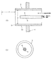
図1は、本発明が適用される竪型溶解炉とその基本的な操業形態を模式的に示したもので、この例では、鉄系スクラップ、鉄含有ダスト/スラッジ塊成化物の1種以上を主たる鉄源とする竪型溶解炉を示している。
図において、1は炉体、2は炉頂に設けられる原料装入部、3は炉下部の周方向において適当な間隔で設けられる複数の羽口(送風羽口)、4はこの羽口3に熱風を供給する熱風管、5は炉体上部に接続される排気ダクト、6は前記排気ダクト5の途中に設けられる集塵装置である。
この溶解炉の大きさ等に本質的な制限はないが、実質的に操業可能若しくは操業上有利なサイズとして、通常は、羽口位置での炉内径が2〜4m程度、炉高が5〜10m程度である。羽口数に制限はないが、通常、4〜12本程度である。
FIG. 1 schematically shows a vertical melting furnace to which the present invention is applied and its basic operation mode. In this example, one or more of iron-based scrap and iron-containing dust / sludge agglomerates are used. This shows a vertical melting furnace with the main iron source.
In the figure, 1 is a furnace body, 2 is a raw material charging section provided at the top of the furnace, 3 is a plurality of tuyere (blower tuyere) provided at appropriate intervals in the circumferential direction of the lower part of the furnace, and 4 is this
Although there is no essential limitation on the size of the melting furnace, etc., the furnace inner diameter at the tuyere position is usually about 2 to 4 m and the furnace height is 5 to 5 as a size that is substantially operable or advantageous in operation. It is about 10m. Although there is no restriction | limiting in the number of tuyere, Usually, it is about 4-12.
このような溶解炉では、炉頂の原料装入部2から鉄源(鉄系スクラップ、鉄含有ダスト/スラッジ塊成化物の1種以上を主体とする鉄源)とコークスを装入するとともに、複数の羽口3から熱風を吹き込み、コークスの燃焼ガスの熱で鉄源を溶解し、溶銑とする。生成した溶銑は炉底部の出銑口から炉外に取り出される。また、炉内では上昇する熱風に伴いダストも生成し、このダストは排気ダクト5を経由して集塵装置6で捕集される。
In such a melting furnace, an iron source (iron source mainly composed of one or more of iron-based scrap and iron-containing dust / sludge agglomerate) and coke are charged from the raw material charging section 2 at the top of the furnace, Hot air is blown from the plurality of
本発明では、少なくとも一部の羽口3内に、酸素噴射管Aと燃料ガス噴射管Bを設置するとともに、当該羽口の先端内径をdとした場合、酸素噴射管Aから炉内に向けて噴射される酸素と燃料ガス噴射管Bから炉内に向けて噴射される燃料ガスとが、羽口先端から炉中心方向における距離d以内の領域(但し、羽口内部の領域を含む)で接触するように構成する。燃料ガス噴射管Bから噴射する燃料ガスには、後述するように、天然ガスやプロパンガスなどが用いられる。
酸素噴射管Aと燃料ガス噴射管Bを設置するのは、炉体1が有する全部の羽口3でもよいし、一部の羽口3でもよい。また、適用する羽口を周期的に変えてもよい。
In the present invention, when the oxygen injection pipe A and the fuel gas injection pipe B are installed in at least some
The oxygen injection pipe A and the fuel gas injection pipe B may be installed in all
以下の各実施形態については、炭材としてコークスを用いる場合を例に説明する。
図2は、本発明の一実施形態における羽口構造を示すもので、図2(a)は羽口の縦断面図、図2(b)は羽口の正面図である。図において、30が羽口管、31が羽口先端である。
この実施形態では、酸素噴射管Aと燃料ガス噴射管Bを並列状に設置したものである。上記のように酸素噴射管Aと燃料ガス噴射管Bは、それぞれから噴射される酸素と燃料ガスとが、羽口先端31から炉中心方向における距離d以内の領域で接触する(したがって、少なくとも一部において混合し、燃焼する)ように配置される。ここで、羽口先端31から炉中心方向における距離d以内の領域には、羽口内部の領域も含まれる。本実施形態では、両噴射管A,Bからそれぞれ噴射される酸素と燃料ガスは、噴射後すぐに羽口内部の領域で接触し、燃焼する。
About each following embodiment, the case where coke is used as a carbon material is demonstrated to an example.
2 shows a tuyere structure according to an embodiment of the present invention. FIG. 2 (a) is a longitudinal sectional view of the tuyere and FIG. 2 (b) is a front view of the tuyere. In the figure, 30 is a tuyere tube and 31 is a tuyere tip.
In this embodiment, the oxygen injection pipe A and the fuel gas injection pipe B are installed in parallel. As described above, in the oxygen injection pipe A and the fuel gas injection pipe B, oxygen and fuel gas injected from each contact in a region within a distance d from the
ここで、酸素噴射管Aと燃料ガス噴射管Bからそれぞれ噴射される酸素と燃料ガスが接触する位置が、羽口先端31から炉中心方向で距離dを超えると、燃料ガスが主に送風空気と燃焼することになり、純酸素は送風空気中に希釈されてしまうので、燃焼温度の増大が抑制されてしまう。化学平衡計算によれば、例えば、都市ガスの主成分であるメタンガスの断熱火炎温度は、空気(25℃)では1954℃(2227K)、熱風(600℃)でも2216℃(2489K)にとどまるので、羽口先におけるコークス表面温度2000℃(2273K)前後の温度と大差ない。一方、純酸素燃焼であれば、断熱火炎温度は2781℃(3054K)まで上昇するので、温度上昇による燃焼速度向上効果が期待できる。
Here, when the position where the oxygen and the fuel gas injected from the oxygen injection pipe A and the fuel gas injection pipe B contact each other exceeds the distance d from the
また、酸素噴射管Aと燃料ガス噴射管Bから噴射される酸素と燃料ガスが接触する位置は、羽口内部であってもよいが、羽口先端31から羽口内方に距離2d以上離れた位置で接触すると、純酸素燃焼による高温火炎からの熱が羽口内面に負荷され、羽口内面の損耗や熱損失の増大につながるので望ましくない。このため酸素噴射管Aと燃料ガス噴射管Bから噴射される酸素と燃料ガスが接触する位置は、羽口先端31から羽口内方に距離2d未満の範囲であることが好ましい。
酸素噴射管Aと燃料ガス噴射管Bは、その各先端が羽口先端31から突出しないように設置される。これら噴射管A,Bの先端が羽口先端31から突出すると、羽口先のコークス充填層内を流下する流鉄によって損耗を生じるので望ましくない。
Further, the position where the oxygen and the fuel gas injected from the oxygen injection pipe A and the fuel gas injection pipe B come into contact with each other may be inside the tuyere, but at a distance of 2d or more from the
The oxygen injection pipe A and the fuel gas injection pipe B are installed such that their tips do not protrude from the
一方、本実施形態のように酸素噴射管Aと燃料ガス噴射管Bの各先端が羽口内部に位置する場合、その先端と羽口先端31との間隔Lは、下記の条件を満足することが好ましい。これは酸素や燃料ガスの噴流ないし火炎が直接羽口内面に接触することを避け、羽口内面への熱負荷を軽減するためである。
L<d/(2tanθ)
但し、θ:ノズル(噴射口)先での噴出ガスの片側の拡がり角度(ガス噴射方向中心に対する片側の拡がり角度)であって、10°とする。
On the other hand, when each tip of the oxygen injection pipe A and the fuel gas injection pipe B is located inside the tuyere as in this embodiment, the distance L between the tip and the
L <d / (2 tan θ)
However, θ is an expansion angle on one side of the ejection gas at the tip of the nozzle (injection port) (an expansion angle on one side with respect to the center of the gas injection direction), and is 10 °.
本発明による羽口構造を有する溶解炉では、酸素噴射管Aと燃料ガス噴射管Bから炉内に向けてそれぞれ酸素と燃料ガスが噴射され、この酸素と燃料ガスは羽口先で接触して燃焼し、羽口先近傍に高温の燃焼ガスが供給され、その領域の雰囲気温度を効果的に上昇させることができる。例えば、一般のキュポラ等の竪型溶解炉の送風温度は600℃前後であるが、このような温度の送風空気(熱風)が赤熱コークスに当たっても、燃焼速度はそれほど大きくはなく、送風空気が有効に燃焼に寄与するのは炉内部で生成する高温のCOガスと接触・燃焼する段階においてである。それ故、羽口先近傍におけるコークスの燃焼・発熱は、あまり活発ではない。これに対して本発明によれば、燃料ガスを純酸素燃焼させる領域が羽口先に形成され、雰囲気ガス温度をコークス燃焼に適切な温度である2000℃前後ないしそれ以上まで高めることができる。燃料ガスを効率的に燃焼させ、羽口先近傍に高温の燃焼ガスを存在させるには、本発明のように燃料ガスと酸素を別々の噴射手段で噴射し、燃料ガスを純酸素燃焼させることが必要である。以上のように、羽口先の雰囲気温度が高められる結果、羽口先近傍領域でのコークスの燃焼・発熱が促進され、溶銑の生産性を向上させることができる。 In the melting furnace having a tuyere structure according to the present invention, oxygen and fuel gas are respectively injected from the oxygen injection pipe A and the fuel gas injection pipe B into the furnace, and the oxygen and the fuel gas are in contact with each other at the tuyere to burn. However, high-temperature combustion gas is supplied in the vicinity of the tuyere, and the ambient temperature in that region can be effectively increased. For example, the blowing temperature of a vertical melting furnace such as a general cupola is around 600 ° C, but even if blowing air (hot air) of such temperature hits reddish coke, the combustion speed is not so high, and the blowing air is effective It is during the stage of contact and combustion with the high-temperature CO gas generated inside the furnace that contributes to combustion. Therefore, the burning and heat generation of coke near the tuyere are not very active. On the other hand, according to the present invention, the region where the fuel gas is burned with pure oxygen is formed at the tip of the tuyere, and the atmospheric gas temperature can be raised to about 2000 ° C. or more, which is a temperature suitable for coke combustion. In order to efficiently burn the fuel gas and make the high-temperature combustion gas exist near the tip of the tuyere, the fuel gas and oxygen are injected by separate injection means as in the present invention, and the fuel gas is burned with pure oxygen is necessary. As described above, as a result of increasing the atmosphere temperature at the tip of the tuyere, coke combustion and heat generation in the vicinity of the tip of the tuyere are promoted, and the productivity of hot metal can be improved.
また、鉄含有ダスト/スラッジ塊成化物を構成するダストやスラッジは、鉄系スクラップに較べて酸化鉄を多く含んでいる。したがって、溶解炉の鉄源として鉄含有ダスト/スラッジ塊成化物を用いる場合、コークスおよび炉内のCOガスにより塊成化物中の酸化鉄が還元され、この還元反応部分では吸熱が生じ、そのままでは温度降下して燃焼・発熱反応が遅滞する恐れがある。これに対して本発明では、上述したようにコークスの燃焼・発熱作用を高めることができるので、鉄含有ダスト/スラッジ塊成化物を鉄源として使用する際の上記課題を有利に解決できる。 Further, the dust and sludge constituting the iron-containing dust / sludge agglomerate contain more iron oxide than iron-based scrap. Therefore, when iron-containing dust / sludge agglomerates are used as the iron source of the melting furnace, iron oxide in the agglomerates is reduced by coke and CO gas in the furnace, and heat is generated in this reduction reaction part. There is a risk that combustion and exothermic reaction may be delayed due to temperature drop. On the other hand, in the present invention, as described above, since the combustion and heat generation action of coke can be enhanced, the above-mentioned problems when using iron-containing dust / sludge agglomerates as an iron source can be advantageously solved.
図3は、本発明の他の実施形態における羽口構造を示すもので、図3(a)は羽口の縦断面図、図3(b)は羽口の正面図である。
本実施形態では、酸素噴射管Aと燃料ガス噴射管Bを2重管状(断面同心円状)に設け、この2重管構造の外管を酸素噴射管Aとし、内管を燃料ガス噴射管Bとしたものである。
このような構造とすることにより、酸素噴射管Aから噴射される酸素と燃料ガス噴射管Bから噴射される燃料ガスの接触状態がより高まるため、燃焼効率がより向上する。このため、羽口先近傍領域でのコークスの燃焼・発熱をより効果的に促進させることができる。
FIG. 3 shows a tuyere structure according to another embodiment of the present invention. FIG. 3 (a) is a longitudinal sectional view of the tuyere and FIG. 3 (b) is a front view of the tuyere.
In the present embodiment, the oxygen injection pipe A and the fuel gas injection pipe B are provided in a double tube (concentric cross section), the outer pipe of this double pipe structure is the oxygen injection pipe A, and the inner pipe is the fuel gas injection pipe B. It is what.
By adopting such a structure, the contact state between the oxygen injected from the oxygen injection pipe A and the fuel gas injected from the fuel gas injection pipe B is further increased, so that the combustion efficiency is further improved. For this reason, the combustion and heat generation of coke in the vicinity of the tuyere can be more effectively promoted.
図4は、本発明の他の実施形態における羽口構造を示すもので、図4(a)は羽口の縦断面図、図4(b)は羽口の正面図である。
本実施形態では、酸素噴射管Aと燃料ガス噴射管Bを2重管状(断面同心円状)に設け、この2重管構造の外管を燃料ガス噴射管Bとし、内管を酸素噴射管Aとしたものである。
このような構造とすることにより、上述したように、燃焼ガスにより羽口先近傍領域の雰囲気温度が上昇し、その領域でのコークスの燃焼・発熱が促進されるという効果が得られるとともに、さらに、次のような効果が得られる。羽口先で生じる燃焼ガス(燃料ガスと酸素および送風空気との燃焼で生じる燃焼ガス)が、酸素噴射管Aから噴射される酸素流を外側から包み込むことで酸素流の膨張・拡散が抑制される。すなわち、酸素噴射管Aから噴射される酸素流の外側に生成する燃焼ガスは、酸素ガスに較べて密度が小さく且つ動粘性係数が大きいため、酸素流の流速を減衰させず且つ酸素流の拡散を抑制し、酸素流の流速および直進性を維持させるに役立つ。このため酸素流は、十分な速度を保ちつつ、それほど拡散しない状態で炉内中心部領域に到達でき、炉中心部領域でのコークスの燃焼・発熱を促進させることができる。その結果、羽口先から炉中心部までの広い領域で、コークスの燃焼・発熱を促進でき、溶銑の生産性をより高めることができる。
4 shows a tuyere structure according to another embodiment of the present invention. FIG. 4A is a longitudinal sectional view of the tuyere, and FIG. 4B is a front view of the tuyere.
In the present embodiment, the oxygen injection pipe A and the fuel gas injection pipe B are provided in a double tube (concentric cross section), the outer pipe of this double pipe structure is the fuel gas injection pipe B, and the inner pipe is the oxygen injection pipe A. It is what.
By adopting such a structure, as described above, the atmosphere temperature in the vicinity of the tuyere tip is increased by the combustion gas, and the effect of promoting the combustion and heat generation of coke in that region is obtained, and further, The following effects are obtained. Combustion gas (combustion gas generated by combustion of fuel gas, oxygen, and blown air) at the tip of the tuyere wraps the oxygen flow injected from the oxygen injection pipe A from the outside, thereby suppressing the expansion and diffusion of the oxygen flow. . That is, the combustion gas generated outside the oxygen flow injected from the oxygen injection pipe A has a lower density and a larger kinematic viscosity coefficient than the oxygen gas, so that the oxygen flow velocity is not attenuated and the oxygen flow is diffused. It helps to maintain the flow rate and straightness of the oxygen flow. Therefore, the oxygen flow can reach the center region in the furnace without diffusing so much while maintaining a sufficient speed, and can promote the combustion and heat generation of coke in the center region of the furnace. As a result, the combustion and heat generation of coke can be promoted in a wide area from the tuyere to the center of the furnace, and the productivity of hot metal can be further increased.
また、さきに述べたように、元々酸化鉄を多く含んでいる鉄含有ダスト/スラッジ塊成化物を溶解炉の鉄源として用いる場合、コークスおよび炉内のCOガスにより酸化鉄が還元され、この還元反応部分では吸熱が生じ、そのままでは温度降下して燃焼・発熱反応が遅滞する恐れがある。特に、炉内径Dが充填層の炭材粒径(調和平均粒径)dpに対して相対的に大きい、D/dp≧30のような条件では、炉中心部領域に送風空気(酸素)が届きにくいので、その懸念が大きくなる。これに対して図4に示すような実施形態では、上述したように炉内中心部領域でのコークスの燃焼・発熱作用を高めることができるので、鉄含有ダスト/スラッジ塊成化物を鉄源として使用する際の上記課題を有利に解決できる。 In addition, as described above, when iron-containing dust / sludge agglomerates that originally contain a large amount of iron oxide are used as the iron source of the melting furnace, iron oxide is reduced by coke and CO gas in the furnace. In the reduction reaction part, endotherm is generated, and if it is left as it is, there is a possibility that the temperature drops and the combustion / exothermic reaction is delayed. In particular, under conditions such as D / dp ≧ 30 where the furnace inner diameter D is relatively large with respect to the carbon particle diameter (harmonic mean particle diameter) dp of the packed bed, blown air (oxygen) is present in the furnace center region. Because it is difficult to reach, the concern is increased. On the other hand, in the embodiment as shown in FIG. 4, since the combustion / heating action of coke in the central region of the furnace can be enhanced as described above, the iron-containing dust / sludge agglomerate is used as the iron source. The said subject at the time of use can be solved advantageously.
図5は、本発明の他の実施形態における羽口構造を示すもので、図5(a)は羽口の縦断面図、図5(b)は羽口の正面図である。また、図5(a)には、両噴射管A,Bのノズル部の拡大断面図を示してある。
本実施形態では、酸素噴射管Aと燃料ガス噴射管Bを2重管状(断面同心円状)に設け、この2重管構造の外管を燃料ガス噴射管Bとし、内管を酸素噴射管Aとするとともに、酸素噴射管Aのノズル部(吐出部)を、酸素を超音速で吐出可能なラバール状(図中、7が絞り部)としたものである。
FIG. 5 shows a tuyere structure in another embodiment of the present invention. FIG. 5A is a longitudinal sectional view of the tuyere, and FIG. 5B is a front view of the tuyere. FIG. 5A shows an enlarged cross-sectional view of the nozzle portions of both the injection pipes A and B.
In the present embodiment, the oxygen injection pipe A and the fuel gas injection pipe B are provided in a double tube (concentric cross section), the outer pipe of this double pipe structure is the fuel gas injection pipe B, and the inner pipe is the oxygen injection pipe A. In addition, the nozzle portion (discharge portion) of the oxygen injection tube A is formed in a Laval shape (7 in the drawing is a throttle portion) that can discharge oxygen at supersonic speed.
このような構造とすることにより、酸素噴射管Aから超音速(ノズル出口流速)の酸素ジェットを噴射することができ、炉中心部領域まで酸素を到達させることがさらに容易となる。これにより、図4の実施形態で述べた効果をさらに高めることができる。特に、炉内径Dとコークス(炭材)の調和平均粒子径dpとの比D/dpが、D/dp≧50というような条件で炉を操業する場合には、従来法では、炉中心部領域にまで酸素が到達しにくいため、炉中心部領域のコークスが燃焼ガス中の炭酸ガス等によりソリューションロス反応(CO2+C=2CO,吸熱反応)を起こし、炉中心部領域での発熱・溶解が停滞する傾向があった。これに対して図5に示すような本発明の実施形態では、D/dp≧50のような条件で操業を行っても、炉中心部領域まで酸素を容易に到達させ、同領域での発熱・溶解を促進させることができる。 With such a structure, a supersonic (nozzle outlet flow velocity) oxygen jet can be injected from the oxygen injection tube A, and it is even easier to make oxygen reach the furnace center region. Thereby, the effect described in the embodiment of FIG. 4 can be further enhanced. In particular, when the furnace is operated under the condition that the ratio D / dp between the furnace inner diameter D and the harmonic mean particle diameter dp of coke (carbon material) is D / dp ≧ 50, Since oxygen is difficult to reach the zone, coke in the furnace center region causes a solution loss reaction (CO 2 + C = 2CO, endothermic reaction) due to carbon dioxide in the combustion gas, and heat generation and melting in the furnace center region Tended to stagnate. On the other hand, in the embodiment of the present invention as shown in FIG. 5, even if the operation is performed under the condition of D / dp ≧ 50, oxygen easily reaches the furnace center region, and heat is generated in the region. -It can promote dissolution.
また、さきに述べたように、元々酸化鉄を多く含んでいる鉄含有ダスト/スラッジ塊成化物を溶解炉の鉄源として用いる場合、コークスおよび炉内のCOガスにより酸化鉄が還元され、この還元反応部分では吸熱が生じ、そのままでは温度降下して燃焼・発熱反応が遅滞する恐れがあり、特に、上記のようなD/dp≧50の条件では、炉中心部領域に送風空気(酸素)が届きにくいので、その懸念が大きくなる。これに対して図5に示すような実施形態では、上述したように炉内中心部領域でのコークスの燃焼・発熱作用を特に高めることができるので、鉄含有ダスト/スラッジ塊成化物を鉄源として使用する際の上記課題を特に有利に解決できる。
酸素噴射管Aのノズル部(吐出部)は、ラバール状ではなく、先細状としてもよい。また、噴射される高速酸素流は、音速以下の流速であってもよい。また、図2,図3の実施形態においても、酸素噴射管Aのノズル部をラバール状または先細状とすることができる。
In addition, as described above, when iron-containing dust / sludge agglomerates that originally contain a large amount of iron oxide are used as the iron source of the melting furnace, iron oxide is reduced by coke and CO gas in the furnace. In the reduction reaction part, endotherm is generated, and if it is left as it is, the temperature may drop and the combustion / exothermic reaction may be delayed. In particular, under the condition of D / dp ≧ 50 as described above, the blown air (oxygen) is supplied to the furnace center region It ’s hard to reach, so the concern grows. On the other hand, in the embodiment as shown in FIG. 5, since the coke combustion and heat generation action in the central region of the furnace can be particularly enhanced as described above, the iron-containing dust / sludge agglomerate is used as the iron source. The above-mentioned problem when used as can be particularly advantageously solved.
The nozzle part (discharge part) of the oxygen injection tube A may be tapered instead of Laval. Further, the jetted high-speed oxygen flow may have a flow velocity equal to or lower than the speed of sound. 2 and 3 also, the nozzle portion of the oxygen injection tube A can be formed in a Laval shape or a tapered shape.
次に、以上述べたような竪型溶解炉を用いた溶銑製造方法について説明する。
この溶銑製造方法では、炉頂部2から鉄源と炭材を装入し、羽口3から熱風を吹き込み、さらに酸素噴射管Aから酸素を、燃料ガス噴射管Bから燃料ガスをそれぞれ噴射し、炭材の燃焼熱で鉄源を溶解することにより溶銑を製造する。
燃料ガス噴射管Bから噴射する燃料ガスに特別な制限はないが、通常、天然ガス、プロパンガス、製鉄プロセスガス、液体燃料気化ガスの1種または2種以上を主成分とするものが用いられる。燃料ガス噴射管Bから噴射する燃料ガス量は、酸素噴射管Aから噴射する酸素によって完全燃焼する量以下とすることが好ましい。
Next, a hot metal manufacturing method using the vertical melting furnace as described above will be described.
In this hot metal manufacturing method, an iron source and a carbon material are charged from the top 2 of the furnace, hot air is blown from the
There is no particular restriction on the fuel gas injected from the fuel gas injection pipe B. Usually, a gas mainly composed of one or more of natural gas, propane gas, iron-making process gas, and liquid fuel vaporized gas is used. . The amount of fuel gas injected from the fuel gas injection pipe B is preferably set to be equal to or less than the amount that is completely burned by oxygen injected from the oxygen injection pipe A.
なお、酸素富化率に特に制限はないが、本発明の効果を得るためには、一般には2vol%以上の酸素富化率とすることが好ましい。一方、酸素富化率が過剰であると、羽口先温度の上昇によって羽口抜熱量が徒に増大するとともに、羽口耐火物の溶損頻度が増大するおそれがある。また、炉径方向での温度分布が大きくなってガス流れの制御が困難になる等の問題を生じやすい。このため酸素富化率は50vol%程度を上限とするのが好ましい。
炉に装入する炭材(コークスなど)の調和平均粒径dpは、炉内径Dに対してD/dp≧30、好ましくはD/dp≧40、より好ましくはD/dp≧50を満足することが望ましい。dpの小さい炭材の方が安価であるので、できるだけD/dpの大きい条件で操業することが、経済性の面からは好ましい。一方で、D/dpが大きいほど、炉中心部側には送風空気(酸素)が届きにくくなるので、炉中心部側での燃焼・発熱が不十分となるとともに、カーボンソリューションロス反応による吸熱が進みやすくなり、炉腹断面積当たりの生産性が低減傾向となる。したがって、本発明はこのようなD/dpの大きい条件において、その有用性が特に大きいと言える。
In addition, although there is no restriction | limiting in particular in an oxygen enrichment rate, in order to acquire the effect of this invention, generally it is preferable to set it as an oxygen enrichment rate of 2 vol% or more. On the other hand, if the oxygen enrichment rate is excessive, the amount of heat extracted from the tuyere increases due to an increase in tuyere tip temperature, and the frequency of erosion of tuyere refractories may increase. In addition, the temperature distribution in the furnace radial direction becomes large, and problems such as difficulty in controlling the gas flow tend to occur. For this reason, the oxygen enrichment rate is preferably about 50 vol% as the upper limit.
The harmonic average particle diameter dp of the carbonaceous material (such as coke) charged in the furnace satisfies D / dp ≧ 30, preferably D / dp ≧ 40, more preferably D / dp ≧ 50 with respect to the furnace inner diameter D. It is desirable. Since carbon materials with a small dp are cheaper, it is preferable from the viewpoint of economy to operate under conditions where the D / dp is as large as possible. On the other hand, the larger the D / dp, the more difficult the blown air (oxygen) reaches the furnace center side, so the combustion and heat generation at the furnace center side becomes insufficient, and the heat absorption due to the carbon solution loss reaction decreases. It becomes easier to proceed, and the productivity per furnace cross-sectional area tends to decrease. Therefore, it can be said that the present invention is particularly useful in such a condition with a large D / dp.
鉄源としては、例えば、鉱石類、鉄系スクラップ、鉄含有ダスト/スラッジ塊成化物などの1種以上が使用され、また炭材としては、一般にコークスが使用されるが、さきに述べたように、本発明の竪型溶解炉は、特に、鉄系スクラップ、鉄含有ダスト/スラッジ塊成化物の1種以上を主たる鉄源とする溶銑製造プロセスに好適なものであるので、以下、この溶銑の製造プロセスについて説明する。 As the iron source, for example, one or more of ores, iron-based scraps, iron-containing dust / sludge agglomerates, etc. are used, and as the carbon material, coke is generally used, but as mentioned above In addition, the vertical melting furnace of the present invention is particularly suitable for a hot metal manufacturing process in which one or more of iron-based scrap and iron-containing dust / sludge agglomerates are used as the main iron source. The manufacturing process will be described.
鉄源として鉄含有ダスト/スラッジ塊成化物を装入すると、鉄系スクラップ単独装入の場合に比べてコークス原単位が増加するため、排ガス量が増加するが、本発明のように送風酸素富化を実施することにより、排ガス量を低減できる。鉄系スクラップと鉄含有ダスト/スラッジ塊成化物を併せて装入する場合、炉内への装入方法は任意であるが、なるべく均一に装入する方が操業の安定性には良い。
鉄源とコークスは、炉内に同時に装入してもよいし、交互に装入してもよい。また、主たる炉装入原料は、鉄系スクラップ、鉄含有ダスト/スラッジ塊成化物の1種以上の鉄源とコークスであるが、それ以外に、例えば、銑鉄、還元鉄、鉄鉱石等の鉄源、木炭や無煙炭等の炭材などを装入してもよい。
When iron-containing dust / sludge agglomerates are charged as the iron source, the amount of exhaust gas increases because the coke unit increases compared to the case of iron-based scrap alone charging. By performing the conversion, the amount of exhaust gas can be reduced. When the iron-based scrap and the iron-containing dust / sludge agglomerate are charged together, the charging method into the furnace is arbitrary, but it is better for the stability of operation to charge as uniformly as possible.
The iron source and coke may be charged into the furnace at the same time or alternately. In addition, the main furnace charging materials are one or more iron sources and coke of iron-based scrap, iron-containing dust / sludge agglomerates, but also iron such as pig iron, reduced iron, iron ore, etc. Sources, charcoal materials such as charcoal and anthracite may be charged.
鉄含有ダスト/スラッジ塊成化物は、鉄含有ダスト、鉄含有スラッジの1種以上またはこれを主体とする原料を塊状に固めたものであればよく、したがって塊成化物の種類や製法を問わないが、一般には、鉄含有ダスト、鉄含有スラッジの1種以上に水硬性バインダーを配合し、さらに必要に応じて還元用の炭材粉などを配合した原料に水を加えて混合した後、成形し、この成形物を水和硬化させて塊成化物としたものが用いられる。 The iron-containing dust / sludge agglomerate may be any one of iron-containing dust, iron-containing sludge, or any material obtained by solidifying a raw material mainly composed of iron-containing dust and sludge. However, in general, one or more types of iron-containing dust and iron-containing sludge are mixed with a hydraulic binder, and if necessary, water is added to the raw material containing carbonaceous powder for reduction, and then molded. The molded product is then hydrated and cured to form an agglomerated product.
前記鉄含有ダストは、酸化鉄及び/又は金属鉄を含むダストであり、その種類に特に制限はないが、代表的なものとしては、鉄鋼製造プロセスで生じる製鋼ダストを挙げることができる。この製鋼ダストには、溶銑予備処理工程で生じる溶銑予備処理ダスト、転炉脱炭工程で生じる転炉ダスト、電気炉で生じる電気炉ダストなどが含まれる。これらの製鋼ダストは、製鋼工程で発生した排ガスから集塵することにより回収されたものである。また、これらの中でも、転炉脱炭工程で生じる転炉ダスト、いわゆるOGダストが、不純物の含有量が少なく、したがって鉄含有量が高いため特に好ましい。また、製鋼ダスト以外の鉄含有ダストとしては、例えば、高炉ダスト、圧延ダストなどがある。
また、前記鉄含有スラッジは、酸化鉄及び/又は金属鉄を含むスラッジであり、その種類に特に制限はないが、上述したような各種ダストが湿式集塵機で捕集されることでスラッジ化したものが、代表例として挙げられる。
The iron-containing dust is dust containing iron oxide and / or metallic iron, and the type thereof is not particularly limited, but typical examples include steel-making dust generated in a steel manufacturing process. The steelmaking dust includes hot metal pretreatment dust generated in the hot metal pretreatment process, converter dust generated in the converter decarburization process, electric furnace dust generated in the electric furnace, and the like. These steelmaking dusts are collected by collecting dust from the exhaust gas generated in the steelmaking process. Among these, converter dust generated in the converter decarburization step, so-called OG dust, is particularly preferable because it has a low impurity content and therefore a high iron content. Examples of iron-containing dust other than steelmaking dust include blast furnace dust and rolling dust.
The iron-containing sludge is a sludge containing iron oxide and / or metallic iron, and there is no particular limitation on the type thereof, but it is sludge formed by collecting various types of dust as described above with a wet dust collector. Is a typical example.
さきに述べたように、鉄含有ダスト/スラッジ塊成化物は、一般には、鉄含有ダストまたは/および鉄含有スラッジに水硬性バインダーを配合し、さらに必要に応じて還元用の炭材粉などを配合した原料に水を加えて混合した後、成形し、この成形物を水和硬化させることにより得られる。
前記水硬性バインダーとしては、例えば、ポルトランドセメント、高炉セメント、アルミナセメント、フライアッシュセメントなどの各種セメント、高炉水砕スラグ微粉末、生石灰などの1種以上を用いることができる。原料中の水硬性バインダーの配合量は、強度の発現及びスラグ生成量の抑制の観点から、一般に2〜25mass%程度とすることが好ましい。
As described above, the iron-containing dust / sludge agglomerate generally contains a hydraulic binder in the iron-containing dust or / and iron-containing sludge, and further contains carbon powder for reduction as required. It can be obtained by adding water to the blended raw material, mixing, molding, and hydrating and curing the molded product.
As said hydraulic binder, 1 or more types, such as various cements, such as a Portland cement, a blast furnace cement, an alumina cement, a fly ash cement, blast furnace granulated slag fine powder, quick lime, can be used, for example. In general, the blending amount of the hydraulic binder in the raw material is preferably about 2 to 25 mass% from the viewpoints of strength development and suppression of slag generation.
前記炭材粉とは炭素を主成分とする粉体のことであり、竪型溶解炉中で酸化鉄の還元材となる。一般に、製鉄用の竪型溶解炉では還元材として塊コークスが用いられるが、塊コークスよりもコークス粉などの炭材粉の方が価格が安く、コスト的に有利なことに加え、酸化鉄と炭素の接触面積が増大するため、酸化鉄の還元反応も速やかに進行する利点がある。炭材粉としては、コークス粉、石炭粉(好ましくは無煙炭粉)、プラスチック粉などの1種以上を用いることができるが、特に、コークス粉などのように揮発分が少ないものが好ましい。また、鉄含有ダスト/スラッジ塊成化物中に大きな炭材が存在すると、その部分から亀裂が生じ、強度を低下させる原因となるため、炭材粉は粒径3mm以下が好ましい。原料中の炭材粉の配合量は、一般に2〜25mass%程度が好ましい。 The carbonaceous material powder is a powder mainly composed of carbon, and becomes a reducing material for iron oxide in a vertical melting furnace. Generally, lump coke is used as a reducing material in a vertical melting furnace for iron making, but carbon powder such as coke powder is less expensive and advantageous in terms of cost than lump coke. Since the contact area of carbon increases, there is an advantage that the reduction reaction of iron oxide proceeds rapidly. As the carbonaceous material powder, one or more types such as coke powder, coal powder (preferably anthracite coal powder), plastic powder and the like can be used, and those having a low volatile content such as coke powder are particularly preferable. Further, if a large carbon material is present in the iron-containing dust / sludge agglomerated material, cracks are generated from the portion, which causes a decrease in strength. Therefore, the carbon material powder preferably has a particle size of 3 mm or less. In general, the blending amount of the carbonaceous powder in the raw material is preferably about 2 to 25 mass%.
また、鉄含有ダスト/スラッジ塊成化物の原料中には、上述した鉄含有ダストまたは/および鉄含有スラッジ、水硬性バインダーおよび炭材粉以外の材料を必要に応じて適宜配合してもよい。例えば、硬化速度調整剤、界面活性剤、ベントナイト、さらには、鉄含有ダスト/スラッジ塊成化物の圧縮強度を高めるための塩化物、原料に適度な粒度分布を与えて成型性を高めるための材料として焼結篩下粉、ミルスケールなどの鉄含有粉粒物、スラグの塩基度を調整するための石灰石、硅石などの粉粒物などの1種以上を配合してもよい。
また、生成するスラグ量をなるべく少なくするという観点から、原料中でのSiO2、Al2O3、CaO、MgOの合計量を25mass%以下とすることが好ましい。当然、これら成分は水硬性バインダーなどに含有されるものも含まれる。
Further, in the raw material of the iron-containing dust / sludge agglomerated material, materials other than the iron-containing dust or / and iron-containing sludge, hydraulic binder and carbonaceous powder described above may be appropriately blended as necessary. For example, curing rate modifiers, surfactants, bentonites, chlorides for increasing the compressive strength of iron-containing dust / sludge agglomerates, materials for imparting an appropriate particle size distribution to the raw materials and enhancing moldability As an additive, one or more of iron-containing granular materials such as sintered sieve powder and mill scale, and limestone for adjusting the basicity of slag, and granular materials such as meteorite may be blended.
Further, from the viewpoint of reducing the amount of slag to be generated as much as possible, the total amount of SiO 2 , Al 2 O 3 , CaO, and MgO in the raw material is preferably set to 25 mass% or less. Of course, these components include those contained in hydraulic binders.
水硬性バインダーを用いて鉄含有ダスト/スラッジ塊成化物を得るには、上述した原料に水を加えて混合した後、成形し、この成形物を水和硬化させる。
水の量は原料の配合によっても異なるが、成形時に圧縮しても水がしみ出てこない最大水量が望ましい。定量的には、JIS−A−1101(コンクリートのスランプ測定方法)に準じた測定においてスランプが0である最大水量となるように調整することが好ましい。水の量が少なすぎると適切に成形できず、また水硬性バインダーの硬化も進行しない。一方、水の量が多すぎて成形時に水がしみ出てくると、その水の処理などに特別な対応が必要になるからである。
In order to obtain an iron-containing dust / sludge agglomerate using a hydraulic binder, water is added to the above-mentioned raw material and mixed, then molded, and this molded product is hydrated and cured.
Although the amount of water varies depending on the composition of the raw material, the maximum amount of water that does not ooze out even when compressed during molding is desirable. Quantitatively, it is preferable to adjust the slump so that the maximum water amount is zero in the measurement according to JIS-A-1101 (method of measuring concrete slump). If the amount of water is too small, it cannot be molded properly, and curing of the hydraulic binder does not proceed. On the other hand, if the amount of water is too large and water oozes out during molding, special measures are required for the treatment of the water.
成形工程は、型枠を用いた成形、押し出し成形、ロールプレス成形など任意の方式で行うことができるが、成形物を高密度にすると鉄含有ダスト/スラッジ塊成化物は高強度化する傾向があるため、できるだけ高密度化に成形することが好ましい。このため原料と水の混合物を圧縮成形し、または加振しつつ圧縮成形することが好ましい。具体的には、ブリケット成形機、プレス成形機、押出成形機などのような圧縮成形機や、これに加振機能を持たせたものなどを用いて成形することが好ましい。
成形物の形状は任意であるが、炉に装入した際の粉化をなるべく抑えるために角部が少ない方が好ましい。また、成形物の大きさも任意であるが、あまり小さいと竪型溶解炉に装入した際に炉の圧力損失を増大させ、一方、あまり大きいと竪型溶解炉に装入した際に塊成化物の中心部の昇温遅れによる還元・溶解遅れを生じるので、一般には容積で20〜2000cm3程度のサイズが好ましい。
The molding process can be performed by any method such as molding using a mold, extrusion molding, roll press molding, etc. However, if the molding is made dense, the iron-containing dust / sludge agglomerate tends to increase in strength. For this reason, it is preferable to mold as high a density as possible. For this reason, it is preferable to compression-mold the mixture of raw material and water or to perform compression molding while vibrating. Specifically, it is preferable to perform molding using a compression molding machine such as a briquette molding machine, a press molding machine, an extrusion molding machine, or the like having a vibration function.
Although the shape of a molded product is arbitrary, in order to suppress powdering at the time of charging to a furnace as much as possible, it is preferable that there are few corners. Also, the size of the molded product is arbitrary, but if it is too small, the pressure loss of the furnace will increase when it is charged into the vertical melting furnace, while if it is too large, it will agglomerate when charged in the vertical melting furnace. In general, a size of about 20 to 2000 cm 3 in volume is preferable because a reduction and dissolution delay due to a temperature rise delay in the center of the compound occurs.
原料と水の混合物を成形して得られた成形物は、水硬性バインダーにより水和硬化させるため、一定期間養生させる。この養生の方法や期間は任意であり、例えば、蒸気による一次養生を行った後、大気下での二次養生を行ってもよい。養生期間は、養生スペースや生産性などの面からはなるべく短い方が好ましいが、養生後の必要強度に応じて適宜選択すればよい。一般には1〜7日間程度が好ましい。
また、鉄含有ダスト/スラッジ塊成化物としては、上述したような水硬性バインダーを用いて成形体を水和硬化させる製法以外の方法で製造されたものでもよい。
A molded product obtained by molding a mixture of a raw material and water is cured for a certain period of time in order to be hydrated and cured by a hydraulic binder. The curing method and period may be arbitrary. For example, after performing primary curing with steam, secondary curing in the atmosphere may be performed. The curing period is preferably as short as possible from the aspects of curing space and productivity, but may be appropriately selected according to the required strength after curing. Generally, about 1 to 7 days is preferable.
Further, the iron-containing dust / sludge agglomerate may be produced by a method other than the production method in which the molded body is hydrated and cured using a hydraulic binder as described above.
図1に示す構造を有する炉床径約2m、羽口数6本、羽口からの有効高さ5mの竪型溶解炉を用いて、以下のような試験を行った。この試験の発明例では、全羽口に図2〜図5のいずれかの構造の酸素噴射管Aと燃料ガス噴射管Bを設置し、羽口送風に加えて、酸素と燃料ガス(天然ガス)の噴射供給を行った。一方、比較例では羽口送風のみを行った。
鉄源には鉄系スクラップ90mass%+鉄含有ダスト/スラッジ塊成化物10mass%を用い、炭材には鋳物コークス40mass%+篩目40mmで篩った篩上の高炉コークス60mass%を用い、出銑温度1500〜1550℃、コークス比130〜200kg/t・pigの条件で操業を行った。
なお、発明例4で用いた酸素噴射管Aは、ノズル部がラバール状のものであり、酸素流のノズル出口流速が超音速(マッハ2程度)となるものである。
The following tests were conducted using a vertical melting furnace having a structure shown in FIG. 1 having a hearth diameter of about 2 m, six tuyere, and an effective height of 5 m from the tuyere. In the example of this test, the oxygen injection pipe A and the fuel gas injection pipe B having the structure shown in FIGS. 2 to 5 are installed in all tuyere, and in addition to the tuyere air blow, oxygen and fuel gas (natural gas) ) Was supplied. On the other hand, in the comparative example, only tuyere ventilation was performed.
Use iron scrap 90 mass% + iron-containing dust / sludge agglomerate 10 mass% as the iron source, and cast iron coke 40 mass% + blast furnace coke 60 mass% on the sieve sieved with 40 mm sieve. The operation was performed under conditions of a soot temperature of 1500 to 1550 ° C. and a coke ratio of 130 to 200 kg / t · pig.
In addition, the oxygen injection pipe A used in Invention Example 4 has a nozzle portion with a Laval shape, and the nozzle outlet flow velocity of the oxygen flow becomes supersonic (about Mach 2).
操業結果を、操業条件とともに表1に示す。表1において、生産インデックスとは、比較例1(従来例)の出銑量を100としたときの出銑量を指数化したものである。本発明例は、いずれも生産性が大きく向上していることが判る。

1 炉体
2 原料装入部
3 羽口
4 熱風管
5 排気ダクト
6 集塵装置
7 絞り部
30 羽口管
31 羽口先端
A 酸素噴射管
B 燃料ガス噴射管
DESCRIPTION OF SYMBOLS 1 Furnace 2 Raw
Claims (8)
少なくとも一部の羽口内に、酸素噴射管と燃料ガス噴射管を設置するとともに、当該羽口の先端内径をdとした場合、前記酸素噴射管から炉内に向けて噴射される酸素と前記燃料ガス噴射管から炉内に向けて噴射される燃料ガスとが、羽口先端から炉中心方向における少なくとも距離d以内の領域(但し、羽口内部の領域を含む)で接触するように構成したことを特徴とする竪型溶解炉。 In a vertical melting furnace in which hot metal is introduced from the top of the furnace, hot air is blown from a plurality of tuyere provided at the bottom of the furnace, and the iron source is melted by the combustion heat of the carbon material. ,
When an oxygen injection pipe and a fuel gas injection pipe are installed in at least a part of the tuyere, and the tip inner diameter of the tuyere is d, oxygen and fuel injected from the oxygen jet pipe into the furnace The fuel gas injected from the gas injection tube into the furnace is configured to come into contact with the area at least within the distance d in the furnace center direction from the tip of the tuyere (including the area inside the tuyere). A vertical melting furnace.
鉄源として、鉄系スクラップ、鉄含有ダストおよび/または鉄含有スラッジの塊成化物の1種以上を炉に装入するとともに、
酸素噴射管から酸素を、燃料ガス噴射管から燃料ガスを、それぞれ炉内に向けて噴射することを特徴とする溶銑製造方法。 A hot metal production method using the vertical melting furnace according to any one of claims 1 to 4,
As an iron source, one or more agglomerates of iron-based scrap, iron-containing dust and / or iron-containing sludge are charged into the furnace,
A hot metal manufacturing method, wherein oxygen is injected from an oxygen injection pipe and fuel gas is injected from a fuel gas injection pipe into a furnace.
Priority Applications (1)
| Application Number | Priority Date | Filing Date | Title |
|---|---|---|---|
| JP2008174028A JP5125819B2 (en) | 2008-07-02 | 2008-07-02 | Vertical melting furnace and hot metal manufacturing method |
Applications Claiming Priority (1)
| Application Number | Priority Date | Filing Date | Title |
|---|---|---|---|
| JP2008174028A JP5125819B2 (en) | 2008-07-02 | 2008-07-02 | Vertical melting furnace and hot metal manufacturing method |
Publications (3)
| Publication Number | Publication Date |
|---|---|
| JP2010014319A true JP2010014319A (en) | 2010-01-21 |
| JP2010014319A5 JP2010014319A5 (en) | 2012-09-06 |
| JP5125819B2 JP5125819B2 (en) | 2013-01-23 |
Family
ID=41700588
Family Applications (1)
| Application Number | Title | Priority Date | Filing Date |
|---|---|---|---|
| JP2008174028A Expired - Fee Related JP5125819B2 (en) | 2008-07-02 | 2008-07-02 | Vertical melting furnace and hot metal manufacturing method |
Country Status (1)
| Country | Link |
|---|---|
| JP (1) | JP5125819B2 (en) |
Cited By (1)
| Publication number | Priority date | Publication date | Assignee | Title |
|---|---|---|---|---|
| JP2016030833A (en) * | 2014-07-25 | 2016-03-07 | Jfeスチール株式会社 | Method for starting ventilation in blast furnace, and burner for hearth part temperature rising |
Citations (7)
| Publication number | Priority date | Publication date | Assignee | Title |
|---|---|---|---|---|
| JPS6217107A (en) * | 1985-07-15 | 1987-01-26 | Goto Gokin Kk | Tuyere |
| JPS6236390U (en) * | 1985-04-15 | 1987-03-04 | ||
| JPH1053804A (en) * | 1996-06-07 | 1998-02-24 | Kawasaki Steel Corp | Burner for blowing pulverized fine coal into blast furnace |
| JPH10237514A (en) * | 1997-02-21 | 1998-09-08 | Kawasaki Steel Corp | Burner for injecting pulverized fine coal into blast furnace |
| JP2002121609A (en) * | 2000-08-10 | 2002-04-26 | Nkk Corp | Method for operating blast furnace by injecting large quantity of pulverized coal |
| JP2005213590A (en) * | 2004-01-29 | 2005-08-11 | Jfe Steel Kk | Method for blowing solid fuel into blast furnace and blowing lance |
| JP2006312757A (en) * | 2005-05-06 | 2006-11-16 | Jfe Steel Kk | Injection lance for gaseous reducing material, blast furnace and blast furnace operation method |
-
2008
- 2008-07-02 JP JP2008174028A patent/JP5125819B2/en not_active Expired - Fee Related
Patent Citations (7)
| Publication number | Priority date | Publication date | Assignee | Title |
|---|---|---|---|---|
| JPS6236390U (en) * | 1985-04-15 | 1987-03-04 | ||
| JPS6217107A (en) * | 1985-07-15 | 1987-01-26 | Goto Gokin Kk | Tuyere |
| JPH1053804A (en) * | 1996-06-07 | 1998-02-24 | Kawasaki Steel Corp | Burner for blowing pulverized fine coal into blast furnace |
| JPH10237514A (en) * | 1997-02-21 | 1998-09-08 | Kawasaki Steel Corp | Burner for injecting pulverized fine coal into blast furnace |
| JP2002121609A (en) * | 2000-08-10 | 2002-04-26 | Nkk Corp | Method for operating blast furnace by injecting large quantity of pulverized coal |
| JP2005213590A (en) * | 2004-01-29 | 2005-08-11 | Jfe Steel Kk | Method for blowing solid fuel into blast furnace and blowing lance |
| JP2006312757A (en) * | 2005-05-06 | 2006-11-16 | Jfe Steel Kk | Injection lance for gaseous reducing material, blast furnace and blast furnace operation method |
Cited By (1)
| Publication number | Priority date | Publication date | Assignee | Title |
|---|---|---|---|---|
| JP2016030833A (en) * | 2014-07-25 | 2016-03-07 | Jfeスチール株式会社 | Method for starting ventilation in blast furnace, and burner for hearth part temperature rising |
Also Published As
| Publication number | Publication date |
|---|---|
| JP5125819B2 (en) | 2013-01-23 |
Similar Documents
| Publication | Publication Date | Title |
|---|---|---|
| KR20120023057A (en) | Blast furnace operation method | |
| JPH0778252B2 (en) | Improvements in or related to iron making with a melting shaft furnace | |
| JP2008111172A (en) | Method for operating blast furnace | |
| US10407744B2 (en) | Production method of granular metallic iron | |
| JP5125819B2 (en) | Vertical melting furnace and hot metal manufacturing method | |
| KR100498100B1 (en) | A method for making molten iron by using hot compaction of fine dri and calcined additives in non-coking coal based iron making process | |
| JP2004183070A (en) | Method for producing molten iron | |
| JP2014505169A (en) | Hot metal manufacturing apparatus and hot metal manufacturing method using the same | |
| JP5439756B2 (en) | Hot metal production method using vertical melting furnace | |
| JP5181878B2 (en) | Hot metal production method | |
| JP5251296B2 (en) | Hot metal production method using vertical melting furnace | |
| RU2343199C1 (en) | Method of blust-furnace hearth flushing | |
| JP5910182B2 (en) | Hot metal manufacturing method using vertical melting furnace | |
| WO2016173248A1 (en) | Flash ironmaking system and method | |
| JP5262354B2 (en) | Hot metal production method using vertical melting furnace | |
| JP5515242B2 (en) | Hot metal production method using vertical melting furnace | |
| JP5181875B2 (en) | Hot metal production method using vertical melting furnace | |
| JP5082678B2 (en) | Hot metal production method using vertical scrap melting furnace | |
| JP4893291B2 (en) | Hot metal production method using vertical scrap melting furnace | |
| JP4157331B2 (en) | How to treat fly ash | |
| JP5251297B2 (en) | Hot metal production method using vertical melting furnace | |
| JP4893290B2 (en) | Hot metal production method using vertical scrap melting furnace | |
| JP2014015653A (en) | Pig iron production method and pig iron production furnace | |
| KR20180062528A (en) | Carbon composite iron oxide briquette comprising the carbon composite comprising volatile matter, and reduction method thereof at oxidation atmosphere | |
| JPH09118907A (en) | Vertical type quick melting furnace |
Legal Events
| Date | Code | Title | Description |
|---|---|---|---|
| A621 | Written request for application examination |
Free format text: JAPANESE INTERMEDIATE CODE: A621 Effective date: 20110421 |
|
| A521 | Request for written amendment filed |
Free format text: JAPANESE INTERMEDIATE CODE: A523 Effective date: 20120724 |
|
| TRDD | Decision of grant or rejection written | ||
| A01 | Written decision to grant a patent or to grant a registration (utility model) |
Free format text: JAPANESE INTERMEDIATE CODE: A01 Effective date: 20121002 |
|
| A01 | Written decision to grant a patent or to grant a registration (utility model) |
Free format text: JAPANESE INTERMEDIATE CODE: A01 |
|
| A61 | First payment of annual fees (during grant procedure) |
Free format text: JAPANESE INTERMEDIATE CODE: A61 Effective date: 20121015 |
|
| R150 | Certificate of patent or registration of utility model |
Free format text: JAPANESE INTERMEDIATE CODE: R150 Ref document number: 5125819 Country of ref document: JP Free format text: JAPANESE INTERMEDIATE CODE: R150 |
|
| FPAY | Renewal fee payment (event date is renewal date of database) |
Free format text: PAYMENT UNTIL: 20151109 Year of fee payment: 3 |
|
| R250 | Receipt of annual fees |
Free format text: JAPANESE INTERMEDIATE CODE: R250 |
|
| LAPS | Cancellation because of no payment of annual fees |