JP2010014071A - Engine start control device for hybrid system - Google Patents
Engine start control device for hybrid system Download PDFInfo
- Publication number
- JP2010014071A JP2010014071A JP2008176234A JP2008176234A JP2010014071A JP 2010014071 A JP2010014071 A JP 2010014071A JP 2008176234 A JP2008176234 A JP 2008176234A JP 2008176234 A JP2008176234 A JP 2008176234A JP 2010014071 A JP2010014071 A JP 2010014071A
- Authority
- JP
- Japan
- Prior art keywords
- engine
- start control
- internal combustion
- combustion engine
- rotational speed
- Prior art date
- Legal status (The legal status is an assumption and is not a legal conclusion. Google has not performed a legal analysis and makes no representation as to the accuracy of the status listed.)
- Granted
Links
Images


Classifications
-
- Y—GENERAL TAGGING OF NEW TECHNOLOGICAL DEVELOPMENTS; GENERAL TAGGING OF CROSS-SECTIONAL TECHNOLOGIES SPANNING OVER SEVERAL SECTIONS OF THE IPC; TECHNICAL SUBJECTS COVERED BY FORMER USPC CROSS-REFERENCE ART COLLECTIONS [XRACs] AND DIGESTS
- Y02—TECHNOLOGIES OR APPLICATIONS FOR MITIGATION OR ADAPTATION AGAINST CLIMATE CHANGE
- Y02T—CLIMATE CHANGE MITIGATION TECHNOLOGIES RELATED TO TRANSPORTATION
- Y02T10/00—Road transport of goods or passengers
- Y02T10/10—Internal combustion engine [ICE] based vehicles
- Y02T10/12—Improving ICE efficiencies
-
- Y—GENERAL TAGGING OF NEW TECHNOLOGICAL DEVELOPMENTS; GENERAL TAGGING OF CROSS-SECTIONAL TECHNOLOGIES SPANNING OVER SEVERAL SECTIONS OF THE IPC; TECHNICAL SUBJECTS COVERED BY FORMER USPC CROSS-REFERENCE ART COLLECTIONS [XRACs] AND DIGESTS
- Y02—TECHNOLOGIES OR APPLICATIONS FOR MITIGATION OR ADAPTATION AGAINST CLIMATE CHANGE
- Y02T—CLIMATE CHANGE MITIGATION TECHNOLOGIES RELATED TO TRANSPORTATION
- Y02T10/00—Road transport of goods or passengers
- Y02T10/60—Other road transportation technologies with climate change mitigation effect
- Y02T10/62—Hybrid vehicles
Abstract
Description
本発明は、ハイブリッドシステムのエンジン始動制御装置に関する。 The present invention relates to an engine start control device for a hybrid system.
ハイブリッドシステムのエンジン始動時において、所定回転数までモータによりクランキングし、所定回転数以上で燃料噴射を開始し、エンジン完爆を判定したらモータによるクランキングを停止することにより、エンジン始動を円滑化することを図った技術が特許文献1に記載されている。
このように、ハイブリッドシステムにおけるエンジン始動時に、モータによるクランキングと同時に燃料噴射が行われると、モータリングによる回転上昇と燃料の燃焼エネルギーによる回転上昇とが相乗的に作用して、エンジン回転数がオーバーシュートしたり振動が増大したりする可能性があった。 Thus, when fuel injection is performed simultaneously with cranking by the motor at the time of engine start in the hybrid system, the increase in rotation due to motoring and the increase in rotation due to the combustion energy of fuel act synergistically, and the engine speed is reduced. There was a possibility of overshoot or increased vibration.
本発明はこのような事情に鑑みてなされたものであり、ハイブリッドシステムにおけるエンジン始動時において、回転数のオーバーシュートや振動の増大を好適に抑制し、円滑なエンジン始動を可能にする技術を提供することを目的とする。 The present invention has been made in view of such circumstances, and provides a technology that enables a smooth engine start by suitably suppressing an increase in rotational overshoot and vibration during engine start in a hybrid system. The purpose is to do.
上記目的を達成するため、本発明は、
内燃機関と、
前記内燃機関以外の動力源である第1の動力源と、
前記内燃機関以外の動力源であって、燃料の燃焼エネルギーによらずに前記内燃機関を動作させる駆動力を出力する第2の動力源と、
を有し、少なくとも前記第1の動力源によって駆動系に駆動力を出力するハイブリッドシステムのエンジン始動制御装置であって、
前記内燃機関に燃料噴射を行う燃料噴射装置と、
前記内燃機関を始動させる場合に、
前記燃料噴射装置による燃料噴射を行わずに前記第2の動力源によって前記内燃機関を駆動して該内燃機関の回転数を上昇させるモータリング始動制御と、
前記第2の動力源による前記内燃機関の駆動を行わずに前記燃料噴射装置による燃料噴射を行って該内燃機関の回転数を上昇させる燃料噴射始動制御と、
を切り替えて実行する始動制御手段と、
を備えることを特徴とする。
In order to achieve the above object, the present invention provides:
An internal combustion engine;
A first power source that is a power source other than the internal combustion engine;
A power source other than the internal combustion engine, wherein the second power source outputs a driving force for operating the internal combustion engine without depending on the combustion energy of the fuel;
An engine start control device for a hybrid system that outputs a driving force to a driving system by at least the first power source,
A fuel injection device for injecting fuel into the internal combustion engine;
When starting the internal combustion engine,
Motoring start control for driving the internal combustion engine by the second power source without increasing the number of revolutions of the internal combustion engine without performing fuel injection by the fuel injection device;
Fuel injection start control for increasing the rotational speed of the internal combustion engine by performing fuel injection by the fuel injection device without driving the internal combustion engine by the second power source;
Starting control means for switching and executing,
It is characterized by providing.
上記構成によれば、内燃機関を始動させる際に、第2の動力源による内燃機関の駆動と、燃料の燃焼エネルギーによる内燃機関の駆動と、が同時に行われることが抑制される。これにより、内燃機関の始動時に、内燃機関に過剰な駆動エネルギーが供給されて振動が増大することや、内燃機関の回転数が過剰に上昇して始動完了時の目標回転数をオーバーシュートしてしまうことを抑制できる。 According to the above configuration, when the internal combustion engine is started, the driving of the internal combustion engine by the second power source and the driving of the internal combustion engine by the combustion energy of the fuel are suppressed. As a result, when the internal combustion engine is started, excessive drive energy is supplied to the internal combustion engine to increase vibrations, or the rotational speed of the internal combustion engine is excessively increased to overshoot the target rotational speed at the completion of startup. Can be suppressed.
本発明において、始動制御手段は、内燃機関の回転数に基づいて、モータリング始動制御と燃料噴射始動制御とを切り替えるようにしても良い。すなわち、始動制御手段は、内燃機関の始動を開始してから、内燃機関の回転数が所定の回転数に達するまでの期間は、モータリング始動制御を行い、内燃機関の回転数が当該所定の回転数に達してから始動完了時の目標回転数に達するまでの期間は、燃料噴射始動制御を行うようにしても良い。 In the present invention, the start control means may switch between motoring start control and fuel injection start control based on the rotational speed of the internal combustion engine. That is, the start control means performs motoring start control during a period from the start of the internal combustion engine until the rotational speed of the internal combustion engine reaches a predetermined rotational speed, and the rotational speed of the internal combustion engine is set to the predetermined rotational speed. The fuel injection start control may be performed during a period from when the rotation speed is reached until the target rotation speed at the completion of the start is reached.
ここで、所定の回転数は、第2の動力源のみによって到達可能な回転数の上限値以下の回転数であれば、目的に応じて任意に設定することができる。 Here, the predetermined number of rotations can be arbitrarily set according to the purpose as long as the number of rotations is not more than the upper limit value of the number of rotations that can be reached only by the second power source.
例えば、低回転状態の内燃機関の回転数を燃料の燃焼エネルギーによって上昇させる場合の燃料消費量は多い。従って、低回転領域においては、燃料の燃焼エネルギーではなくなるべく第2の動力源によって内燃機関の回転数を上昇させるようにすれば、内燃機関の始動時の燃費特性を向上させることができる。この場合、第2の動力源のみによって到達可能な回転数の上限値を、上記構成における「所定の回転数」に設定することができる。 For example, there is a large amount of fuel consumed when the rotational speed of an internal combustion engine in a low speed state is increased by the combustion energy of fuel. Therefore, in the low speed region, if the rotational speed of the internal combustion engine is increased by the second power source so as not to be the combustion energy of the fuel, the fuel efficiency characteristics at the start of the internal combustion engine can be improved. In this case, the upper limit value of the rotational speed that can be reached only by the second power source can be set to the “predetermined rotational speed” in the above configuration.
また、内燃機関の低回転領域には、内燃機関と駆動系との共振の大きさが大きくなる回転数領域が存在する。共振が大きくなる回転数領域は、内燃機関や駆動系の構造や重量等の諸元によって決まる固有の回転数の範囲である。このような共振が大きい回転数領域(以下「共振領域」という)において燃料噴射が行われると、共振に起因して発生する振動が大きくなり易い。従って、内燃機関の回転数が共振領域に含まれるときには、燃料の燃焼エネルギーではなくなるべく第2の動力源によって内燃機関の回転数を上昇させるようにすれば、内燃機関の始動時の振動を抑制できる。この場合、共振領域を予め実験等により求めておき、当該共振領域の上限値を、上記構成における「所定の回転数」に設定することができる。 Further, in the low speed region of the internal combustion engine, there is a rotational speed region where the magnitude of resonance between the internal combustion engine and the drive system becomes large. The rotation speed region in which the resonance becomes large is a specific rotation speed range determined by specifications such as the structure and weight of the internal combustion engine and the drive system. When fuel injection is performed in such a rotational speed region where resonance is large (hereinafter referred to as “resonance region”), vibration generated due to resonance tends to increase. Therefore, when the rotational speed of the internal combustion engine is included in the resonance region, if the rotational speed of the internal combustion engine is increased by the second power source so as not to be the combustion energy of the fuel, vibration at the start of the internal combustion engine is suppressed. it can. In this case, the resonance region can be obtained in advance by experiments or the like, and the upper limit value of the resonance region can be set to the “predetermined rotational speed” in the above configuration.
また、内燃機関の始動時の振動又は振動に相関する量を測定し、その測定結果に基づいて共振領域を学習し、学習結果に基づいて、当該共振領域ではモータリング始動制御を行うようにしても良い。例えば、本発明において、内燃機関の回転変動及び/又はトルク変動を測定する測定手段を更に備え、測定された内燃機関の回転変動又はトルク変動に基づいて、内燃機関の回転数が共振領域に含まれるか否かを判定するようにしても良い。そして、モータリング始動制御を実行しながら、回転変動又はトルク変動の測定結果に基づいて、回転数が共振領域を超えたと判定された後の任意のタイミングで、燃料噴射始動制御に切り替えるようにしても良い。 Further, the vibration at the time of starting the internal combustion engine or an amount correlated with the vibration is measured, the resonance region is learned based on the measurement result, and the motoring start control is performed in the resonance region based on the learning result. Also good. For example, the present invention further includes a measuring means for measuring the rotational fluctuation and / or torque fluctuation of the internal combustion engine, and the rotational speed of the internal combustion engine is included in the resonance region based on the measured rotational fluctuation or torque fluctuation of the internal combustion engine. It may also be determined whether or not. Then, while executing the motoring start control, the fuel injection start control is switched at an arbitrary timing after it is determined that the rotational speed has exceeded the resonance region based on the measurement result of the rotation fluctuation or torque fluctuation. Also good.
特に、本発明のハイブリッドシステムにおいて、第2の動力源としてモータを備えた場合、該モータによってモータリングされる内燃機関の回転変動やトルク変動を、該モータのモータトルクやモータ回転数の制御に基づいて精度良く測定できるので、上記の構成は特に有効である。 In particular, in the hybrid system of the present invention, when a motor is provided as the second power source, the rotational fluctuation or torque fluctuation of the internal combustion engine motored by the motor is used to control the motor torque or the motor rotational speed of the motor. The above configuration is particularly effective because the measurement can be performed with high accuracy.
本発明において、内燃機関の吸気通路に設けられた吸気絞り弁を更に備え、始動制御手段は、モータリング始動制御を行う時に、燃料噴射始動制御を行う場合と比較して、吸気絞り弁の開度を閉じ側の開度に設定するようにしても良い。こうすることで、内燃機関における圧縮仕事が低減されるので、モータリング始動制御実行時の内燃機関の振動をより一層低減することができる。モータリング始動制御を行う場合、燃料を燃焼させる必要はないので、内燃機関に空気を供給する必要はない。従って、吸気絞り弁を全閉又は全閉に近い開度まで閉じ側にすることもできる。 In the present invention, an intake throttle valve provided in the intake passage of the internal combustion engine is further provided, and the start control means opens the intake throttle valve when performing the motoring start control as compared with the case of performing the fuel injection start control. The degree may be set to the opening on the closing side. By doing so, the compression work in the internal combustion engine is reduced, so that the vibration of the internal combustion engine when the motoring start control is executed can be further reduced. When performing the motoring start control, it is not necessary to burn the fuel, so it is not necessary to supply air to the internal combustion engine. Accordingly, the intake throttle valve can be closed to the fully closed position or close to the fully closed position.
本発明において、内燃機関の吸気通路に設けられたコンプレッサ及び排気通路に設けられたタービンを有するターボチャージャを更に備え、該ターボチャージャが、該タービンに開度可変のノズルベーンを備え、該ノズルベーンの開度を開き側の開度にすることでそ
の過給効率を低くすることが可能な可変容量型のターボチャージャである場合、始動制御手段は、モータリング始動制御を行う時に、燃料噴射始動制御を行う場合と比較して、ノズルベーンの開度を開き側の開度に設定するようにしても良い。こうすることで、内燃機関における圧縮仕事が低減されるので、モータリング始動制御実行時の内燃機関の振動をより一層低減することができる。
The present invention further includes a turbocharger having a compressor provided in an intake passage of an internal combustion engine and a turbine provided in an exhaust passage, and the turbocharger includes a nozzle vane having a variable opening degree, and the nozzle vane is opened. In the case of a variable capacity turbocharger that can reduce the supercharging efficiency by setting the opening degree to the opening side, the start control means performs the fuel injection start control when performing the motoring start control. Compared with the case where it performs, you may make it set the opening degree of a nozzle vane to the opening degree of an opening side. By doing so, the compression work in the internal combustion engine is reduced, so that the vibration of the internal combustion engine when the motoring start control is executed can be further reduced.
本発明のハイブリッドシステムにおいて、第2の動力源は、第1の動力源の余剰動力によって構成しても良い。すなわち、本発明のハイブリッドシステムを、動力源として内燃機関及び第1の動力源を備え、少なくとも第1の動力源の駆動力によって駆動系に駆動力を出力するハイブリッドシステムとして構成し、第1の動力源の出力可能な駆動力のうち、駆動系の要求駆動力を出力した残りの余剰動力によって、燃料の燃焼エネルギーによらずに内燃機関を動作させるようにしても良い。例えば、車両停止状態における内燃機関の始動時のように、駆動系の要求駆動力がゼロであるような条件下では、第1の動力源の全動力をモータリング始動制御を行うための動力として利用することもできる。こうすることで、本発明に係るハイブリッドシステムを、内燃機関以外の動力源として第1の動力源のみを備えた簡易な構成とすることができる。 In the hybrid system of the present invention, the second power source may be configured by surplus power of the first power source. That is, the hybrid system of the present invention is configured as a hybrid system that includes an internal combustion engine and a first power source as a power source, and outputs a driving force to the driving system by at least the driving force of the first power source. Of the driving force that can be output from the power source, the remaining surplus power that outputs the required driving force of the driving system may be used to operate the internal combustion engine regardless of the combustion energy of the fuel. For example, under conditions where the required driving force of the drive system is zero, such as when the internal combustion engine is started when the vehicle is stopped, the entire power of the first power source is used as the power for performing the motoring start control. It can also be used. By doing so, the hybrid system according to the present invention can have a simple configuration including only the first power source as a power source other than the internal combustion engine.
本発明により、ハイブリッドシステムにおけるエンジン始動時において、振動の増大や回転数のオーバーシュートを抑制し、円滑なエンジン始動が可能になる。 According to the present invention, when the engine is started in the hybrid system, an increase in vibration and an overshoot of the rotational speed are suppressed, and a smooth engine start is possible.
以下、本発明の実施例を図面に基づいて説明する。 Embodiments of the present invention will be described below with reference to the drawings.
図1は、本発明に係るハイブリッドシステムのエンジン始動制御装置が適用されたハイブリッドシステムの概略構成を表すブロック図である。 FIG. 1 is a block diagram showing a schematic configuration of a hybrid system to which an engine start control device of a hybrid system according to the present invention is applied.
このハイブリッドシステムは、動力源としてエンジン1と、第1モータジェネレータ(以下「MG1」という)と、第2モータジェネレータ(以下「MG2」という)と、を有する。エンジン1の動力は動力分割機構3によってMG1及び出力部4に分配出力される。動力分割機構3は、公知の遊星歯車機構によって構成される。MG2の動力は出力部4に出力される。出力部4に出力されたエンジン1及びMG2の動力は、伝達部8を介して、このハイブリッドシステムが搭載された車両の駆動輪40を駆動する駆動力として、駆動輪40に伝達される。伝達部8はドライブシャフトやディファレンシャルギア等の公知の構成を有する。
This hybrid system has an
MG1は、モータ又は発電機として機能する同期電動発電機である。 MG1 is a synchronous motor generator that functions as a motor or a generator.
MG1は、バッテリ25から供給される電力及び/又は発電機として動作した場合のMG2によって発電される電力によって、モータとして動作することができる。モータとして動作した場合のMG1の動力は、動力分割機構3を介してエンジン1をモータリングする駆動力としてエンジン1の出力軸(クランクシャフト)に出力される。
MG1 can operate as a motor by electric power supplied from
ここで、エンジン1をモータリングする、とは、エンジン1を、燃料の燃焼による内燃エネルギーによらずに外力によって機械的に回転駆動させることを意味する。本実施例のハイブリッドシステムでは、MG1の動力によってエンジン1モータリングすることができるので、エンジン1において燃料噴射が行われない状態や、エンジン1が自立回転するために必要な噴射量に満たない微少量燃料噴射が行われる状態においても、エンジン1を動作させることができる。
Here, motoring the
また、エンジン1において通常の燃料噴射が行われる状態、すなわちエンジン1が負荷運転する状態においても、MG1の動力によってエンジン1の動作状態を外部から規定することができる。これにより、例えば負荷運転するエンジン1を、一定の回転数で安定的に動作する状態に維持すること等が可能である。本実施例では、負荷運転するエンジン1の動作状態を、MG1の動力によって外部から制御することも、エンジン1をモータリングすることに含まれるものとする。
Further, even in a state where normal fuel injection is performed in the
MG1は、動力分割機構3を介してMG1に分配されるエンジン1の動力によって駆動されて、発電機として動作することができる。発電機として動作した場合のMG1によって発電される電力は、バッテリ25を充電するための電力及び/又はMG2をモータとして動作させるための電力として消費される。
MG1 is driven by the power of
MG2も、モータ又は発電機として機能する同期電動発電機である。 MG2 is also a synchronous motor generator that functions as a motor or a generator.
MG2は、バッテリ25から供給される電力及び/又は発電機として動作した場合のMG1によって発電される電力によって、モータとして動作することができる。モータとして動作した場合のMG2の動力は、出力部4を介して、駆動輪40を駆動するための駆動力として駆動輪40に伝達される。
MG2 can operate as a motor by the electric power supplied from
MG2は、伝達部8及び出力部4を介して伝達される駆動輪40の運動エネルギーによって駆動されて、発電機として動作することができる。発電機として動作した場合のMG2によって発電される電力は、バッテリ25を充電するための電力及び/又はMG1をモータとして動作させるための電力として消費される。この場合、駆動輪40の運動エネルギーによって回生発電が行われ、駆動輪40に対する制動力となる。
The
インバータ24は、バッテリ25から供給される直流電力を交流電力に変換してMG1及びMG2に供給するとともに、発電機として動作した場合にMG1及びMG2から供給される交流電力を直流電力に変換してバッテリ25に供給する。
The
エンジン1はディーゼルエンジンである。図2に、エンジン1の吸排気系及び制御系の概略構成を示す。
The
エンジン1は4気筒エンジンであり、各シリンダ49には、エンジン1の燃焼室内に燃料を直接噴射供給するインジェクタ29が備えられている。エンジン1には、燃焼室内に空気を供給する吸気通路42と、燃焼室内の既燃ガスを排出するための排気通路43と、が接続されている。吸気通路42の途中には、吸気通路42内の吸気の流量を調節するスロットルバルブ22が備えられている。スロットルバルブ22より下流側にはターボチャージャ13のコンプレッサ11が備えられている。排気通路43の途中にはターボチャージャ13のタービン12が備えられている。ターボチャージャ13は、開度可変のノズルベーン5をタービン12に備え、ノズルベーン5の開度を変更することによって過給効率を変更可能な可変容量型のターボチャージャである。具体的には、ノズルベーン5の開度を開き側にするほど、ターボチャージャ13の過給効率は低くなる。
The
図1、図2に基づいて、このハイブリッドシステムの制御系について説明する。 The control system of this hybrid system will be described with reference to FIGS.
このハイブリッドシステムは、ハイブリッドシステム全体の動作を制御するコンピュータユニットであるECU26を備える。ECU26は、CPU、ROM、RAM等の公知の構成を有する電子制御コンピュータである。
This hybrid system includes an
ECU26には、エンジン1の冷却水の温度を測定する水温センサ48、エンジン1の筒内圧を測定する筒内圧センサ50、エンジン1のクランクシャフトの回転角度を測定するクランク角度センサ30、アクセルペダル52の踏み込み量を測定するアクセル開度センサ27、ハイブリッドシステムが搭載された車両の車速を測定する車速センサ28、バッテリ25の充電状態を取得するSOCセンサ51、MG1の回転数を測定するMG1回転数センサ31、MG2の回転数を測定するMG2回転数センサ32、その他ハイブリッドシステム及び車両の各種の状態量を測定するセンサ装置が接続されており、各センサによって測定された状態量の情報がECU26に入力される。
The
また、ECU26には、ノズルベーン5、スロットルバルブ22、インジェクタ29、インバータ24、その他ハイブリッドシステム及び車両の各種の装置を駆動するアクチュエータ等が接続されており、前記各センサから入力される情報に基づいてこれら各機器の動作を駆動制御する制御信号を出力する。
Further, the
ECU26は、車速センサ28からの車速情報と、アクセル開度センサ27からのアクセル開度情報から演算される要求駆動力と、SOCセンサ51からのバッテリ充電状態情報と、に基づいて、例えば燃費が最適となる運転モードを選択し、現在選択されている運転モードから当該選択された運転モードへ遷移するよう、エンジン1、MG1、MG2の制御を行う。選択された運転モードに応じて、エンジン1の運転/停止(燃料噴射の実行/停止)や、MG1/MG2の力行/発電の状態が切り替えられる。
The
エンジン1の始動時には、バッテリ25の電力によってMG1がモータとして動作し、エンジン1をモータリング(クランキング)することによってエンジン1の始動が開始される。そしてエンジン1の回転数が所定の回転数に達した時点で、インジェクタ29により燃料噴射が開始されるとともにMG1によるエンジン1のモータリングが停止される。このエンジン始動時の制御に本実施例の特徴点がある。エンジン始動制御の詳細については後述する。
When the
車両の発進時には、エンジン1は暖機のための運転を行い、車両走行のための要求駆動力をMG2によって出力する。バッテリ25の充電状態が低下している場合には、エンジン1はMG1を発電機として駆動するための運転を行い、MG1の発電する電力によってバッテリ25の充電を行う。
When the vehicle starts, the
低負荷走行時には、エンジン1における燃料噴射が停止され、エンジン1は停止する。車両走行のための要求駆動力をMG2によって出力する。バッテリ25の充電状態が低下している場合には、エンジン1はMG1を発電機として駆動するための運転を行い、MG1の発電する電力によってバッテリ25の充電を行う。
During low load traveling, fuel injection in the
通常走行時には、車両走行のための要求駆動力は主としてエンジン1によって出力する。また、エンジン1の動力のうち動力分割機構3によってMG1を発電機として動作させ、MG1で発電した電力によりMG2をモータとして動作させ、MG2の動力によってエンジン1をアシストする。MG1の発電した電力の一部はバッテリ25の充電に当てられる。
During normal traveling, the required driving force for traveling the vehicle is mainly output by the
制動要求時には、駆動輪40の回転エネルギーをMG2に伝達してMG2を発電機として動作させて回生発電による制動が行われる。バッテリ25の充電状態が高く、回生発電によって発電された電力を消費することができない場合は、駆動輪40の回転エネルギーをエンジン1に伝達してエンジンブレーキによる制動が行われる。
When the braking is requested, the rotational energy of the
ECU26は、アクセル開度センサ27から入力されるアクセル開度情報とクランク角
度センサ30から入力されるクランク角度情報とに基づいて、現在のエンジン負荷及びエンジン回転数を把握する。そして、運転状態に応じて求められる車両走行用の要求駆動力や、SOCセンサ51からのバッテリ25の充電状態情報やエアコン等の補機類の要求電力等に応じて求められるMG1の発電用の要求駆動力に基づいて、エンジン1の要求出力を算出する。そして、エンジン1の要求出力に基づいて、スロットルバルブ22やインジェクタ29等の機器に対する制御信号を出力する。
The
ECU26は、運転状態に応じてMG1/MG2の力行/発電の要求動作状態、MG1及びMG2の要求出力回転数及び要求出力トルクを求め、MG1及びMG2をそれぞれ独立に制御する指令をインバータ24に出力する。インバータ24は、ECU26からの指令に従い、バッテリ25から供給される直流電圧からMG1及びMG2へ供給する三相交流電流を生成する。
The
ここで、本実施例のハイブリッドシステムにおけるエンジン1の始動制御について説明する。
Here, the start control of the
本実施例では、停止状態のエンジン1を始動させる要求が発生した場合、まず、インジェクタ29による燃料噴射を行わずに、MG1によってエンジン1をモータリングすることによって、エンジン1の回転数を上昇させるモータリング始動制御を行う。そして、エンジン1の回転数が所定の基準回転数NE1に達した時点で、MG1によるエンジンモータリングを停止するとともに、インジェクタ29による燃料噴射を開始し、燃料の燃焼エネルギーによってエンジン1の回転数を上昇させる燃料噴射始動制御を行う。そして、エンジン1の始動が完了したと判定可能な目標回転数NE2までエンジン1の回転数が上昇した時点で、エンジン1の始動制御を終了し、後続する負荷運転モードに移行する。
In the present embodiment, when a request for starting the
以上説明した本実施例におけるエンジン1の始動制御の実行手順について、図3のフローチャートに基づいて説明する。このフローチャートによって表されるエンジン始動制御ルーチンは、ハイブリッドシステムの稼働中繰り返し実行される。
The execution procedure of the start control of the
ステップS101において、ECU26は、停止状態のエンジン1を始動させる要求が発生したか否かを判定する。例えば、ハイブリッドシステムが、MG2のみによって車両走行のための要求駆動力を出力する運転モード(EV走行モード)から、エンジン1を負荷運転させる走行モードに遷移する場合に、停止状態のエンジン1を始動させる要求が発生する。ステップS101においてエンジン始動要求が発生したと判定された場合(Yes)、ECU26はステップS102に進む。ステップS101においてエンジン始動要求はないと判定された場合(No)、ECU26は本ルーチンを一旦抜ける。
In step S101, the
ステップS102において、ECU26は、インジェクタ29による燃料噴射を行わない無噴射状態とするとともに、MG1によってエンジン1をモータリングすることによって、エンジン1の回転数を上昇させるモータリング始動制御を開始する。この時、更に、スロットルバルブ22を閉弁するとともに、ノズルベーン5の開度を、後述する燃料噴射始動制御実行時のノズルベーン5の開度ON2より開き側の開度ON1に設定する。
In step S102, the
ステップS103において、ECU26は、クランク角度センサ30からのクランク角度情報に基づいて、エンジン1の回転数NEを取得する。
In step S103, the
ステップS104において、ECU26は、ステップS103で取得したエンジン1の回転数NEが所定の基準回転数NE1以上になったか否かを判定する。ここでは、基準回転数NE1は、MG1によって到達可能なエンジン1の回転数の上限値NEsupに定められる。ステップS104においてエンジン回転数NEが基準回転数NE1以上になった
と判定された場合(Yes)、ECU26はステップS105に進む。ステップS104においてエンジン回転数NEが基準回転数NE1以上になっていないと判定された場合(No)、ECU26はステップS103に戻る。
In step S104, the
ステップS105において、ECU26は、MG1によるエンジン1のモータリングを停止するとともに、インジェクタ29によりアイドル噴射量の燃料噴射を開始し、燃料の燃焼エネルギーによってエンジン1の回転数を上昇させる燃料噴射始動制御を開始する。この時、燃料を燃焼させるための空気を供給する必要があるため、スロットルバルブ22を開弁するとともに、ノズルベーン5の開度を、前述のモータリング始動制御実行時のノズルベーン5の開度ON1より閉じ側の開度ON2に設定する。
In step S105, the
ステップS106において、ECU26は、クランク角度センサ30からのクランク角度情報に基づいて、エンジン1の回転数NEを取得する。
In step S106, the
ステップS107において、ECU26は、ステップS106で取得したエンジン1の回転数NEがエンジン始動時の目標回転数NE2以上になったか否かを判定する。ステップS107においてエンジン回転数NEが目標回転数NE2以上になったと判定された場合(Yes)、ECU26はステップS108に進む。ステップS107においてエンジン回転数NEが目標回転数NE2以上になっていないと判定された場合(No)、ECU26はステップS106に戻る。
In step S107, the
ステップS108において、ECU26は、エンジン1の始動が完了したと判断する。
In step S108, the
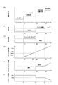
以上説明した本実施例のエンジン始動制御を実行した場合の、ハイブリッドシステムの運転モード、インジェクタ29による燃料噴射量、MG1の動作状態、エンジン1の回転数、スロットルバルブ22の開度、ノズルベーン5の開度の時間変化の一例を、図4に示す。
The hybrid system operation mode, the fuel injection amount by the
図4(A)はハイブリッドシステムの運転モードを表す。ここでは、エンジン1の運転を停止させるとともにMG2のみによって車両走行のための要求駆動力を出力する運転モード(EV走行モード)でハイブリッドシステムが動作している状態から、時刻t1において、エンジン1を始動させる状態にハイブリッドシステムが遷移する場合を例に説明する。
FIG. 4A shows the operation mode of the hybrid system. Here, the
時刻t1においてエンジン1を始動させる要求がECU26にもたらされると、図4(C)に示すように、MG1がバッテリ25の電力によってモータとして動作してエンジン1をモータリングする状態となる。更に、図4(B)に示すように、インジェクタ29による燃料噴射が行われないフューエルカット状態となる。すなわち、時刻t1において、燃料の燃焼エネルギーによらずに、MG1によるモータリングによってエンジン1の回転数を上昇させるモータリング始動制御が開始される。
When a request to start the
この時、図4(E)に示すように、スロットルバルブ22が閉弁されるとともに、図4(F)に示すように、ノズルベーン5が大開度ON1に設定される。こうすることで、エンジン1に吸入される空気量が減少するので、エンジン1における圧縮仕事を低減させることができる。これにより、モータリング始動制御時のエンジン1の振動を好適に抑制することが可能となる。
At this time, as shown in FIG. 4 (E), the
モータリング始動制御によってエンジン1の回転数が上昇し、基準回転数NE1に達した時点(時刻t1)で、図4(C)に示すように、MG1によるエンジン1のモータリングが停止される。更に、図4(B)に示すように、インジェクタ29によりアイドル噴射
量の燃料噴射が行われ、燃料の燃焼エネルギーによってエンジン1の回転数を上昇させる燃料噴射始動制御が開始される。
At the time (time t1) when the rotation speed of the
この時、図4(E)に示すように、スロットルバルブ22が開弁されるとともに、図4(F)に示すように、ノズルベーン5が小開度ON2に設定される。こうすることにより、エンジン1に噴射供給される燃料が燃焼するために十分な空気が供給されるようになる。
At this time, as shown in FIG. 4 (E), the
燃料噴射始動制御によりエンジン1の回転数がさらに上昇してエンジン始動時の目標回転数NE2に達した時点(時刻t2)で、エンジン1の始動が完了したと判断されて、エンジン1の制御モードは通常の負荷運転モードに遷移する。
It is determined that the start of the
以上説明したように、本実施例におけるエンジン1の始動制御では、エンジン1の回転数を上昇させるエネルギー源として、MG1の駆動力及びインジェクタ29により噴射供給される燃料の燃焼エネルギーが用いられるが、これらが両方同時に用いられることはない。すなわち、エンジン1の始動開始から基準回転数NE1までの低回転領域では、MG1によるモータリングのみによってエンジン1の回転数を上昇させ、この時燃料噴射は行われない。一方、エンジン1の回転数が基準回転数NE1以上の、それ以上MG1のモータリング駆動力によっては到達できない高回転領域では、アイドル噴射量の燃料噴射が行われて燃料の燃焼エネルギーによってエンジン1の回転数を上昇させ、この時MG1によるモータリングは行われない。
As described above, in the starting control of the
これにより、MG1の駆動力と燃料の燃焼エネルギーとが相乗的に作用してエンジン1の振動が増大したり回転数が目標回転数を超えてオーバーシュートしたりすることを抑制できる。
As a result, the driving force of the
また、本実施例では、モータリング始動制御時にはスロットルバルブ22の閉弁及びノズルベーン5の大開度設定により、エンジン1に吸入される吸気量が低減されるので、圧縮仕事による振動の発生をも好適に抑制することが可能である。
Further, in the present embodiment, at the time of motoring start control, the intake air amount sucked into the
また、一般に、停止状態や低回転状態のエンジンの回転数を燃料の燃焼エネルギーによって上昇させる場合の燃料消費量は多い。従って、エンジン始動開始直後は、なるべく燃料の燃焼エネルギーではなくMG1によるモータリングによってエンジン1の回転数を上昇させるようにすれば、エンジン始動時の燃料消費量を低減することができる。
In general, the amount of fuel consumed is high when the engine speed in a stopped state or in a low speed state is increased by the combustion energy of the fuel. Therefore, immediately after the start of the engine, if the rotational speed of the
この点、本実施例では、モータリング始動制御から燃料噴射始動制御へ切り替える基準回転数NE1が、MG1のみによって到達可能なエンジン回転数の上限値NEsupに定められるので、エンジン始動時の燃料消費量を好適に低減することができる。 In this respect, in the present embodiment, the reference rotational speed NE1 for switching from the motoring start control to the fuel injection start control is set to the upper limit value NEsup of the engine speed that can be reached only by MG1, so that the fuel consumption at the time of engine start Can be suitably reduced.
なお、基準回転数NE1は、MG1のみによって到達可能なエンジン回転数の上限値NEsupより低回転側の回転数であれば、目的に応じて任意に設定することができる。例えば、エンジン1の低回転領域には、エンジン1と伝達部8、駆動輪40等の駆動系との共振の大きさが大きくなる回転数領域が存在する。共振が大きくなる回転数領域は、エンジン1や駆動系の構造や重量等の諸元によって決まる固有の回転数の範囲である。このような共振が大きい回転数領域(以下、「共振領域」という)において燃料噴射が行われると、共振に起因して発生する振動が大きくなり易い。従って、エンジン1の回転数が共振領域に含まれる時は、なるべく燃料の燃焼エネルギーではなくMG1によるモータリングによってエンジン1の回転数を上昇させるようにすれば、エンジン始動時の振動を低減することができる。
The reference rotational speed NE1 can be arbitrarily set according to the purpose as long as the rotational speed is lower than the upper limit value NEsup of the engine rotational speed that can be reached only by MG1. For example, the low-speed region of the
このような目的で基準回転数NE1を決定する場合は、共振領域の上限値より高回転側の回転数であってMG1により到達可能な上限回転数NEsupより低回転側の回転数を基準回転数NE1に設定することもできる。こうすることで、エンジン1の回転数が共振領域内に含まれる状況ではモータリング始動制御によって回転数の上昇が行われ、エンジン回転数が共振領域を超えた状態で燃料噴射始動制御へ切り替えられることになる。よって、エンジン回転数が共振領域内に含まれる時に燃料噴射が行われて大きな振動が生じることを好適に抑制することができる。
When determining the reference rotational speed NE1 for such a purpose, the rotational speed higher than the upper limit value of the resonance region and lower than the upper limit rotational speed NEsup that can be reached by MG1 is set as the reference rotational speed. It can also be set to NE1. By doing so, in a situation where the rotational speed of the
図4(D)にこの共振領域の例を示す。図4(D)において、NEk1≦NE≦NEk2を満たす回転数領域が共振領域である。共振領域は、エンジン1の振動が所定の許容レベルを超える回転数範囲として、実験等により求められる。上記実施例1の場合、エンジン回転数NEが基準回転数NE1(実施例1の場合、NEsup)に達した時点t2でモータリング始動制御から燃料噴射始動制御への切り替えが行われているが、基準回転数NE1を共振領域の上限値NEk2に設定した場合、エンジン回転数NEが共振領域の上限値NEk2に達する時点t2’においてモータリング始動制御から燃料噴射始動制御への切り替えが行われることになる。
FIG. 4D shows an example of this resonance region. In FIG. 4D, the rotational speed region satisfying NEk1 ≦ NE ≦ NEk2 is the resonance region. The resonance region is obtained by experiments or the like as a rotation speed range in which the vibration of the
上記実施例で説明したように、エンジン始動時の振動を低減するために、車両やエンジンの構造等に基づいて予め共振領域を求め、求められた共振領域において燃料噴射始動制御が実行されないように基準回転数NE1を設定することもできる。一方、予め共振領域を求めなくても、エンジン始動時における振動や振動に相関する状態量をモニタし、共振が大きくなる回転数領域や運転条件を学習し、その学習結果に基づいてエンジン始動時のモータリング始動制御と燃料噴射始動制御の切り替えを行うこともできる。 As described in the above embodiment, in order to reduce the vibration at the time of starting the engine, a resonance region is obtained in advance based on the structure of the vehicle and the engine so that the fuel injection start control is not executed in the obtained resonance region. The reference rotational speed NE1 can also be set. On the other hand, even if the resonance region is not obtained in advance, vibrations at the time of engine start-up and state quantities correlated with vibration are monitored, and the engine speed region and operating conditions where resonance increases are learned. It is also possible to switch between the motoring start control and the fuel injection start control.
例えば、上記実施例のように、エンジン1を燃料の燃焼エネルギーによらずに動作させる動力源としてモータ(MG1)を用いる場合、MG1のモータトルクやモータ回転数制御に基づいて、MG1がモータリングするエンジン1のエンジントルクやエンジン回転数の変動を正確にモニタすることができる。エンジントルクやエンジン回転数の変動は、エンジン1の振動に相関すると考えられるので、エンジントルクやエンジン回転数の変動に基づいて、エンジン回転数が共振領域に入っているか否か推定することができる。
For example, when the motor (MG1) is used as a power source for operating the
そこで、エンジン始動時のモータリング始動制御実行時に、MG1によってエンジン1のエンジントルクやエンジン回転数の変動を測定し、測定結果に基づいて、エンジン1の回転数が共振領域を超えたと判断された時点又はそれ以降のタイミングで、モータリング始動制御から燃料噴射始動制御に切り替えるようにしても良い。
Therefore, when executing the motoring start control at the time of starting the engine, the engine torque of the
図5は、このようなエンジン始動制御を行う場合のエンジン始動制御ルーチンを表すフローチャートである。ハイブリッドシステムの稼働中、上記実施例で説明した図3のルーチンの代わりに、このエンジン始動制御ルーチンを実行するようにしても良い。 FIG. 5 is a flowchart showing an engine start control routine when such engine start control is performed. During operation of the hybrid system, this engine start control routine may be executed instead of the routine of FIG. 3 described in the above embodiment.
ステップS201において、ECU26は、停止状態のエンジン1を始動させる要求が発生したか否かを判定する。ステップS201においてエンジン始動要求が発生したと判定された場合(Yes)、ECU26はステップS202に進む。ステップS201においてエンジン始動要求はないと判定された場合(No)、ECU26は本ルーチンを一旦抜ける。
In step S201, the
ステップS202において、ECU26は、モータリング始動制御を行う。すなわち、インジェクタ29による燃料噴射を行わない無噴射状態とするとともに、MG1によってエンジン1をモータリングすることによって、エンジン1の回転数を上昇させる。更に、スロットルバルブ22を閉弁するとともに、ノズルベーン5の開度をON1に設定する。
In step S202, the
ステップS203において、ECU26は、MG1のモータトルク制御又はモータ回転数制御に基づいて、MG1がモータリングするエンジン1のエンジントルク又はエンジン回転数の変動を測定する。
In step S203, the
ステップS204において、ECU26は、ステップS203で測定したエンジン1のエンジントルク又は回転数の変動に基づいて、エンジン1の回転数が共振領域を超えたか否かを判定する。エンジン回転数が共振領域内にある場合、エンジントルクやエンジン回転数の変動が大きくなるが、エンジン回転数が共振領域を超えると、エンジントルクやエンジン回転数の変動は小さくなる。従って、このようなエンジン回転数やエンジントルクの動きをモニタして、エンジン回転数が共振領域を超えたと推定される場合(Yes)、ECU26はステップS205に進む。一方、エンジントルクやエンジン回転数の変動が徐々に大きくなっている状況等、未だエンジン回転数が共振領域内にある、又は共振領域を超えていない、と推定される場合(No)、ECU26はステップS203に戻る。
In step S204, the
ステップS205において、ECU26は、MG1によるエンジン1のモータリングを停止してモータリング始動制御を終了するとともに、インジェクタ29によりアイドル噴射量の燃料噴射を開始して燃料噴射始動制御を開始する。この時、スロットルバルブ22を開弁するとともに、ノズルベーン5の開度をON2に設定する。
In step S205, the
ステップS206において、ECU26は、クランク角度センサ30からのクランク角度情報に基づいて、エンジン1の回転数NEを取得する。
In step S206, the
ステップS207において、ECU26は、ステップS206で取得したエンジン1の回転数NEがエンジン始動時の目標回転数NE2以上になったか否かを判定する。ステップS207においてエンジン回転数NEが目標回転数NE2以上になったと判定された場合(Yes)、ECU26はステップS208に進む。ステップS207においてエンジン回転数NEが目標回転数NE2以上になっていないと判定された場合(No)、ECU26はステップS206に戻る。
In step S207, the
ステップS208において、ECU26は、エンジン1の始動が完了したと判断する。
In step S208, the
なお、上記図5のルーチンでは、MG1の制御に基づいてエンジン1のトルク又は回転数を測定する例について説明したが、エンジン1のトルクや回転数を測定する方法はこれに限られない。例えば、筒内圧センサ50によって測定されるエンジン1の筒内圧の変化に基づいてエンジントルクを算出することもできる。
In the routine of FIG. 5 described above, the example of measuring the torque or the rotational speed of the
なお、以上述べた実施例は本発明を説明するための一例であって、本発明の本旨を逸脱しない範囲内において上記の実施例には種々の変更を加え得る。例えば、上記実施例では、車両走行用の駆動力を出力するMG2と、エンジン1をモータリングする駆動力を出力するMG1と、を別個の装置として備えたハイブリッドシステムに本発明を適用した例を説明したが、車両走行用の駆動力を出力するMG2が車両走行用の駆動力を出力した残りの余剰動力によってエンジン1のモータリングするように構成し、エンジン1以外の動力源としてMG2のみを備えたハイブリッドシステムに本発明を適用することもできる。
The above-described embodiment is an example for explaining the present invention, and various modifications can be made to the above-described embodiment without departing from the gist of the present invention. For example, in the above-described embodiment, an example in which the present invention is applied to a hybrid system including MG2 that outputs a driving force for driving a vehicle and MG1 that outputs a driving force for motoring the
その場合、例えばEV走行状態からのエンジン始動時には、MG2に供給する電力を増加させて、車両をEV走行させるための駆動力に加えて更にエンジン1をモータリングするための駆動力をMG2に出力させることにより、モータリング始動制御を開始する。そして、エンジン回転数が基準回転数NE1を超えた時点や、エンジントルクやエンジン回転数の測定からエンジン回転数が共振領域を超えたと判定された時に、MG2に供給する
電力を元に戻して、MG2に車両をEV走行させるための駆動力を出力させる状態とするとともに、インジェクタ29による燃料噴射を開始して燃料噴射始動制御を開始する。
In that case, for example, when the engine is started from the EV traveling state, the electric power supplied to MG2 is increased, and in addition to the driving force for causing the vehicle to EV travel, the driving force for
上記実施例におけるエンジン1が、本発明の内燃機関に相当する。MG1が第2の動力源に相当する。MG2が第1の動力源に相当する。インジェクタ29が燃料噴射装置に相当する。図3又は図5に示したエンジン始動制御を実行するECU26が、始動制御手段に相当する。MG1のモータトルク又はモータ回転数の制御に基づいてMG1がモータリングするエンジン1のエンジントルク又はエンジン回転数を推定する場合のMG1が、測定手段に相当する。スロットルバルブ22が吸気絞り弁に相当する。
The
1 エンジン
3 動力分割機構
4 出力部
5 ノズルベーン
8 伝達部
11 コンプレッサ
12 タービン
13 ターボチャージャ
22 スロットルバルブ
24 インバータ
25 バッテリ
26 ECU
27 アクセル開度センサ
28 車速センサ
29 インジェクタ
30 クランク角度センサ
31 MG1回転数センサ
32 MG2回転数センサ
40 駆動輪
42 吸気通路
43 排気通路
48 水温センサ
49 シリンダ
50 筒内圧センサ
51 SOCセンサ
52 アクセルペダル
DESCRIPTION OF
27
Claims (7)
前記内燃機関以外の動力源である第1の動力源と、
前記内燃機関以外の動力源であって、燃料の燃焼エネルギーによらずに前記内燃機関を動作させる駆動力を出力する第2の動力源と、
を有し、少なくとも前記第1の動力源によって駆動系に駆動力を出力するハイブリッドシステムのエンジン始動制御装置であって、
前記内燃機関に燃料噴射を行う燃料噴射装置と、
前記内燃機関を始動させる場合に、
前記燃料噴射装置による燃料噴射を行わずに前記第2の動力源によって前記内燃機関を駆動して該内燃機関の回転数を上昇させるモータリング始動制御と、
前記第2の動力源による前記内燃機関の駆動を行わずに前記燃料噴射装置による燃料噴射を行って該内燃機関の回転数を上昇させる燃料噴射始動制御と、
を切り替えて実行する始動制御手段と、
を備えることを特徴とするハイブリッドシステムのエンジン始動制御装置。 An internal combustion engine;
A first power source that is a power source other than the internal combustion engine;
A power source other than the internal combustion engine, wherein the second power source outputs a driving force for operating the internal combustion engine without depending on the combustion energy of the fuel;
An engine start control device for a hybrid system that outputs a driving force to a driving system by at least the first power source,
A fuel injection device for injecting fuel into the internal combustion engine;
When starting the internal combustion engine,
Motoring start control for driving the internal combustion engine by the second power source without increasing the number of revolutions of the internal combustion engine without performing fuel injection by the fuel injection device;
Fuel injection start control for increasing the rotational speed of the internal combustion engine by performing fuel injection by the fuel injection device without driving the internal combustion engine by the second power source;
Starting control means for switching and executing,
An engine start control device for a hybrid system, comprising:
前記始動制御手段は、前記内燃機関の回転数が、所定の回転数に達するまでは、前記モータリング始動制御を行い、それ以後は前記燃料噴射始動制御を行うことを特徴とするハイブリッドシステムのエンジン始動制御装置。 In claim 1,
The start control means performs the motoring start control until the rotational speed of the internal combustion engine reaches a predetermined rotational speed, and thereafter performs the fuel injection start control. Start control device.
前記始動制御手段は、前記内燃機関の回転数が、前記内燃機関と前記駆動系との共振の大きさが所定の基準より大きくなる回転数領域より速い所定の回転数に達するまでは、前記モータリング始動制御を行い、それ以後は前記燃料噴射始動制御を行うことを特徴とするハイブリッドシステムのエンジン始動制御装置。 In claim 1,
The start control means is configured to rotate the motor until the rotational speed of the internal combustion engine reaches a predetermined rotational speed that is faster than a rotational speed region where the magnitude of resonance between the internal combustion engine and the drive system is larger than a predetermined reference. An engine start control device for a hybrid system, which performs ring start control and thereafter performs the fuel injection start control.
前記内燃機関の回転変動及び/又はトルク変動を測定する測定手段を更に備え、
前記始動制御手段は、前記測定手段により測定される前記内燃機関の回転変動又はトルク変動に基づいて、前記内燃機関の回転数が、前記共振の大きさが所定の基準より大きくなる回転数領域に、含まれるか否かを判定することを特徴とするハイブリッドシステムのエンジン始動制御装置。 In claim 3,
Measuring means for measuring rotational fluctuations and / or torque fluctuations of the internal combustion engine,
The start control means is configured so that the rotational speed of the internal combustion engine is in a rotational speed region in which the magnitude of the resonance is larger than a predetermined reference based on the rotational fluctuation or torque fluctuation of the internal combustion engine measured by the measuring means. The engine start control device for a hybrid system is characterized by determining whether or not it is included.
前記内燃機関の吸気通路に設けられた吸気絞り弁を更に備え、
前記始動制御手段は、前記モータリング始動制御を行う時に、前記燃料噴射始動制御を行う時と比較して、前記吸気絞り弁を閉じ側の開度にすることを特徴とするハイブリッドシステムのエンジン始動制御装置。 In any one of Claims 1-4,
An intake throttle valve provided in the intake passage of the internal combustion engine,
The start control means is configured to start the engine of the hybrid system, when performing the motoring start control, and opening the intake throttle valve at a closing side as compared with when performing the fuel injection start control. Control device.
前記内燃機関の吸気通路に設けられたコンプレッサ及び該内燃機関の排気通路に設けられたタービンを有するターボチャージャを更に備え、該ターボチャージャは、該タービンに開度可変のノズルベーンを備え、該ノズルベーンの開度を開き側の開度にすることでその過給効率を低くすることが可能な可変容量型のターボチャージャであり、
前記始動制御手段は、前記モータリング始動制御を行う時に、前記燃料噴射始動制御を行う時と比較して、前記ノズルベーンの開度を開き側の開度にすることを特徴とするハイブリッドシステムのエンジン始動制御装置。 In any one of Claims 1-5,
A turbocharger further comprising a compressor provided in an intake passage of the internal combustion engine and a turbine provided in an exhaust passage of the internal combustion engine, the turbocharger comprising a nozzle vane having a variable opening degree, It is a variable capacity turbocharger that can reduce the supercharging efficiency by opening the opening to the opening side,
The engine of the hybrid system characterized in that the start control means sets the opening of the nozzle vane to an opening on the open side when performing the motoring start control compared to when performing the fuel injection start control. Start control device.
前記第2の動力源は、前記第1の動力源の余剰動力であることを特徴とするハイブリッドシステムのエンジン始動制御装置。 In any one of Claims 1-6,
The engine start control device for a hybrid system, wherein the second power source is surplus power of the first power source.
Priority Applications (1)
| Application Number | Priority Date | Filing Date | Title |
|---|---|---|---|
| JP2008176234A JP5040834B2 (en) | 2008-07-04 | 2008-07-04 | Engine start control device for hybrid system |
Applications Claiming Priority (1)
| Application Number | Priority Date | Filing Date | Title |
|---|---|---|---|
| JP2008176234A JP5040834B2 (en) | 2008-07-04 | 2008-07-04 | Engine start control device for hybrid system |
Publications (2)
| Publication Number | Publication Date |
|---|---|
| JP2010014071A true JP2010014071A (en) | 2010-01-21 |
| JP5040834B2 JP5040834B2 (en) | 2012-10-03 |
Family
ID=41700386
Family Applications (1)
| Application Number | Title | Priority Date | Filing Date |
|---|---|---|---|
| JP2008176234A Expired - Fee Related JP5040834B2 (en) | 2008-07-04 | 2008-07-04 | Engine start control device for hybrid system |
Country Status (1)
| Country | Link |
|---|---|
| JP (1) | JP5040834B2 (en) |
Cited By (10)
| Publication number | Priority date | Publication date | Assignee | Title |
|---|---|---|---|---|
| JP2011213132A (en) * | 2010-03-31 | 2011-10-27 | Honda Motor Co Ltd | Hybrid vehicle |
| KR20140052858A (en) * | 2012-10-24 | 2014-05-07 | 로베르트 보쉬 게엠베하 | Method for detecting a stable combustion |
| JP2015511195A (en) * | 2012-02-06 | 2015-04-16 | ローベルト ボッシュ ゲゼルシャフト ミット ベシュレンクテル ハフツング | Method for calibrating an exhaust sensor and a fuel metering device in a hybrid vehicle |
| JP2015161190A (en) * | 2014-02-26 | 2015-09-07 | 株式会社豊田自動織機 | engine |
| JP2015197067A (en) * | 2014-04-01 | 2015-11-09 | 株式会社デンソー | Engine starter |
| JP2016098708A (en) * | 2014-11-20 | 2016-05-30 | いすゞ自動車株式会社 | Starting device of engine |
| JP2017066928A (en) * | 2015-09-29 | 2017-04-06 | 株式会社デンソー | Engine control device |
| JP2018119525A (en) * | 2017-01-27 | 2018-08-02 | 株式会社デンソー | Electronic control device for vehicle |
| WO2020208391A1 (en) * | 2019-04-12 | 2020-10-15 | 日産自動車株式会社 | Control method and control device for internal combustion engine |
| JP7438637B2 (en) | 2020-10-14 | 2024-02-27 | ダイハツ工業株式会社 | Hybrid vehicle control device |
Families Citing this family (1)
| Publication number | Priority date | Publication date | Assignee | Title |
|---|---|---|---|---|
| DE112014006571B4 (en) | 2014-04-10 | 2021-08-05 | Mitsubishi Electric Corporation | Engine start control device |
Citations (8)
| Publication number | Priority date | Publication date | Assignee | Title |
|---|---|---|---|---|
| JPH1082332A (en) * | 1996-07-18 | 1998-03-31 | Toyota Motor Corp | Drive unit |
| JPH11153075A (en) * | 1997-09-17 | 1999-06-08 | Toyota Motor Corp | Starting control device of internal combustion engine |
| JPH11178113A (en) * | 1997-12-12 | 1999-07-02 | Toyota Motor Corp | Driving controller of hybrid vehicle |
| JP2001112118A (en) * | 1999-10-08 | 2001-04-20 | Toyota Motor Corp | Hybrid drive apparatus |
| JP2001123857A (en) * | 1996-07-18 | 2001-05-08 | Toyota Motor Corp | Drive device |
| JP2006282162A (en) * | 2005-03-11 | 2006-10-19 | Toyota Motor Corp | Power output device, its controlling method, and automobile |
| JP2006315510A (en) * | 2005-05-12 | 2006-11-24 | Toyota Motor Corp | Power output device and its control method, and automobile |
| JP2007278146A (en) * | 2006-04-05 | 2007-10-25 | Nissan Motor Co Ltd | Start device for internal combustion engine |
-
2008
- 2008-07-04 JP JP2008176234A patent/JP5040834B2/en not_active Expired - Fee Related
Patent Citations (8)
| Publication number | Priority date | Publication date | Assignee | Title |
|---|---|---|---|---|
| JPH1082332A (en) * | 1996-07-18 | 1998-03-31 | Toyota Motor Corp | Drive unit |
| JP2001123857A (en) * | 1996-07-18 | 2001-05-08 | Toyota Motor Corp | Drive device |
| JPH11153075A (en) * | 1997-09-17 | 1999-06-08 | Toyota Motor Corp | Starting control device of internal combustion engine |
| JPH11178113A (en) * | 1997-12-12 | 1999-07-02 | Toyota Motor Corp | Driving controller of hybrid vehicle |
| JP2001112118A (en) * | 1999-10-08 | 2001-04-20 | Toyota Motor Corp | Hybrid drive apparatus |
| JP2006282162A (en) * | 2005-03-11 | 2006-10-19 | Toyota Motor Corp | Power output device, its controlling method, and automobile |
| JP2006315510A (en) * | 2005-05-12 | 2006-11-24 | Toyota Motor Corp | Power output device and its control method, and automobile |
| JP2007278146A (en) * | 2006-04-05 | 2007-10-25 | Nissan Motor Co Ltd | Start device for internal combustion engine |
Cited By (13)
| Publication number | Priority date | Publication date | Assignee | Title |
|---|---|---|---|---|
| JP2011213132A (en) * | 2010-03-31 | 2011-10-27 | Honda Motor Co Ltd | Hybrid vehicle |
| JP2015511195A (en) * | 2012-02-06 | 2015-04-16 | ローベルト ボッシュ ゲゼルシャフト ミット ベシュレンクテル ハフツング | Method for calibrating an exhaust sensor and a fuel metering device in a hybrid vehicle |
| KR102038897B1 (en) | 2012-10-24 | 2019-10-31 | 로베르트 보쉬 게엠베하 | Method for detecting a stable combustion |
| KR20140052858A (en) * | 2012-10-24 | 2014-05-07 | 로베르트 보쉬 게엠베하 | Method for detecting a stable combustion |
| JP2015161190A (en) * | 2014-02-26 | 2015-09-07 | 株式会社豊田自動織機 | engine |
| JP2015197067A (en) * | 2014-04-01 | 2015-11-09 | 株式会社デンソー | Engine starter |
| JP2016098708A (en) * | 2014-11-20 | 2016-05-30 | いすゞ自動車株式会社 | Starting device of engine |
| JP2017066928A (en) * | 2015-09-29 | 2017-04-06 | 株式会社デンソー | Engine control device |
| JP2018119525A (en) * | 2017-01-27 | 2018-08-02 | 株式会社デンソー | Electronic control device for vehicle |
| WO2020208391A1 (en) * | 2019-04-12 | 2020-10-15 | 日産自動車株式会社 | Control method and control device for internal combustion engine |
| JPWO2020208391A1 (en) * | 2019-04-12 | 2020-10-15 | ||
| JP7173301B2 (en) | 2019-04-12 | 2022-11-16 | 日産自動車株式会社 | CONTROL METHOD AND CONTROL DEVICE FOR INTERNAL COMBUSTION ENGINE |
| JP7438637B2 (en) | 2020-10-14 | 2024-02-27 | ダイハツ工業株式会社 | Hybrid vehicle control device |
Also Published As
| Publication number | Publication date |
|---|---|
| JP5040834B2 (en) | 2012-10-03 |
Similar Documents
| Publication | Publication Date | Title |
|---|---|---|
| JP5040834B2 (en) | Engine start control device for hybrid system | |
| JP4519085B2 (en) | Control device for internal combustion engine | |
| JP5505509B2 (en) | Power train, control method and control apparatus for internal combustion engine | |
| JP5825129B2 (en) | Control device for hybrid vehicle | |
| US20190283730A1 (en) | Control system for hybrid vehicle | |
| EP2893175A1 (en) | Internal combustion engine control for a hybrid vehicle | |
| JP2010014072A (en) | Engine stop control device for hybrid system | |
| JP2008105555A (en) | Control device of hybrid vehicle | |
| US9796376B2 (en) | Hybrid vehicle, control method for hybrid vehicle, and controller for hybrid vehicle | |
| JP5198398B2 (en) | Power output device, hybrid vehicle, and lower limit storage ratio update method | |
| JP2013047059A (en) | Hybrid vehicle | |
| JP5278963B2 (en) | Vehicle control device | |
| JP2012021425A (en) | In-vehicle internal combustion engine control device | |
| JP6361684B2 (en) | Control device for hybrid vehicle | |
| JP2010221744A (en) | Vehicle control device | |
| JP2016113977A (en) | Control device for engine | |
| US11230280B2 (en) | Hybrid vehicle and method of controlling hybrid vehicle | |
| JP6028724B2 (en) | Hybrid vehicle control device | |
| JP2013112101A (en) | Hybrid vehicle | |
| JP2006170053A (en) | Internal combustion engine control device and method of hybrid vehicle | |
| JP6009978B2 (en) | Hybrid car | |
| JP2010200570A (en) | Battery temperature rise controller of electric vehicle | |
| JP2004036518A (en) | Control device for compression self-ignition type internal combustion engine | |
| JP4710188B2 (en) | Power generation control device for power generator and power generation control method | |
| JP2016074233A (en) | Hybrid electric vehicle |
Legal Events
| Date | Code | Title | Description |
|---|---|---|---|
| A621 | Written request for application examination |
Free format text: JAPANESE INTERMEDIATE CODE: A621 Effective date: 20101101 |
|
| A977 | Report on retrieval |
Free format text: JAPANESE INTERMEDIATE CODE: A971007 Effective date: 20120529 |
|
| TRDD | Decision of grant or rejection written | ||
| A01 | Written decision to grant a patent or to grant a registration (utility model) |
Free format text: JAPANESE INTERMEDIATE CODE: A01 Effective date: 20120612 |
|
| A01 | Written decision to grant a patent or to grant a registration (utility model) |
Free format text: JAPANESE INTERMEDIATE CODE: A01 |
|
| A61 | First payment of annual fees (during grant procedure) |
Free format text: JAPANESE INTERMEDIATE CODE: A61 Effective date: 20120625 |
|
| R151 | Written notification of patent or utility model registration |
Ref document number: 5040834 Country of ref document: JP Free format text: JAPANESE INTERMEDIATE CODE: R151 |
|
| FPAY | Renewal fee payment (event date is renewal date of database) |
Free format text: PAYMENT UNTIL: 20150720 Year of fee payment: 3 |
|
| LAPS | Cancellation because of no payment of annual fees |