JP2010013271A - Physical distribution reel - Google Patents
Physical distribution reel Download PDFInfo
- Publication number
- JP2010013271A JP2010013271A JP2008176901A JP2008176901A JP2010013271A JP 2010013271 A JP2010013271 A JP 2010013271A JP 2008176901 A JP2008176901 A JP 2008176901A JP 2008176901 A JP2008176901 A JP 2008176901A JP 2010013271 A JP2010013271 A JP 2010013271A
- Authority
- JP
- Japan
- Prior art keywords
- flange
- core
- printed matter
- reel
- physical distribution
- Prior art date
- Legal status (The legal status is an assumption and is not a legal conclusion. Google has not performed a legal analysis and makes no representation as to the accuracy of the status listed.)
- Granted
Links
- 238000009826 distribution Methods 0.000 title claims abstract description 24
- 238000001746 injection moulding Methods 0.000 claims description 7
- 229920005989 resin Polymers 0.000 abstract description 11
- 239000011347 resin Substances 0.000 abstract description 11
- 239000000463 material Substances 0.000 abstract description 10
- 238000000465 moulding Methods 0.000 abstract description 5
- 235000013372 meat Nutrition 0.000 description 11
- 230000002093 peripheral effect Effects 0.000 description 9
- 238000004804 winding Methods 0.000 description 7
- 229920003002 synthetic resin Polymers 0.000 description 4
- 239000000057 synthetic resin Substances 0.000 description 4
- 230000000694 effects Effects 0.000 description 2
- 238000004519 manufacturing process Methods 0.000 description 2
- 238000000034 method Methods 0.000 description 2
- 230000003014 reinforcing effect Effects 0.000 description 2
- 238000005299 abrasion Methods 0.000 description 1
- 230000004323 axial length Effects 0.000 description 1
- 238000005520 cutting process Methods 0.000 description 1
- 238000002347 injection Methods 0.000 description 1
- 239000007924 injection Substances 0.000 description 1
- 238000007726 management method Methods 0.000 description 1
- 238000012986 modification Methods 0.000 description 1
- 230000004048 modification Effects 0.000 description 1
- 230000000414 obstructive effect Effects 0.000 description 1
- 230000009291 secondary effect Effects 0.000 description 1
- 239000004065 semiconductor Substances 0.000 description 1
- 238000007493 shaping process Methods 0.000 description 1
- 125000006850 spacer group Chemical group 0.000 description 1
- 239000002699 waste material Substances 0.000 description 1
Images

Abstract
Description
本発明は、電子部品や半導体の実装・搬送・保管等に供されるTAB(Tape Automated Bonding)テープ、キャリアテープ、スペーサーテープ等のテープ類、或いは、その他各種の帯状、線状、又はチェーン状をなす可撓性長尺物を巻き取って、それらの輸送や管理、繰り出し作業等に供される物流用リールに関し、特に、合成樹脂材料の射出成形によって形成される物流用リールにあって、フランジの表面に各種情報を記載したシールを貼付しやすいように配慮した物流用リールに関する。 The present invention relates to tapes such as TAB (Tape Automated Bonding) tape, carrier tape, spacer tape, etc. used for mounting, transporting, and storing electronic components and semiconductors, or other various belts, lines, or chains. In relation to logistics reels that are used for the transportation and management of such flexible long objects, and for delivery work, etc., particularly in logistics reels formed by injection molding of synthetic resin materials, The present invention relates to a physical distribution reel that is easy to affix a sticker with various information on the surface of a flange.
なお、本発明にいう物流用リールとは、魚釣り用リールや糸巻リール等と区別して、主に産業用に供されるリールであることを明瞭化するための表現である。 Note that the physical distribution reel in the present invention is an expression for clarifying that it is a reel mainly used for industrial purposes, as distinguished from a fishing reel or a spool reel.
長尺物の巻き取りに利用される一般的な物流用リールは、巻芯となる略円筒形状のコアと、該コアの両端に設けられた一対の円盤状のフランジとを備えている。 A general distribution reel used for winding a long object includes a substantially cylindrical core as a winding core and a pair of disk-shaped flanges provided at both ends of the core.
このような物流用リールのうち、特に合成樹脂材料の射出成形によって形成される樹脂製リールにあっては、成形に要する合成樹脂材料をできるだけ節約して軽量化及びコストダウンを図りつつ、実用的な強度や寸法精度を確保することが要求される。そのため、従来の射出成形製リールは、例えば特許文献1、2等に開示されているように、フランジの肉厚をできるだけ薄くするとともに、フランジに複数の窓開口を形成し、窓開口間にはコア側から外周側へと延びるスポークを設ける一方、フランジの外周縁や、窓開口を囲むスポークの側縁には肉厚のリブを形成して、フランジの撓み変形に対する剛性を高めるのが一般的である。
この種の物流用リールにあっては、巻き取られる長尺物の品名、品番、長さや幅等の仕様、工場名や製造者名、その他詳細な情報が、ラベルやシールに印刷されてフランジの外面に貼着されることが多い。とりわけ、電子部品の実装工程等に利用される物流用リールにあっては、ラベルやシール等(以下、「印刷物」と言う。)に記載される情報量がきわめて多く、したがって、それらを記載するための印刷物も大きくなる。特に近年では、複数枚の印刷物を貼着したり、各種情報をバーコードで併記したりするケースが増えており、これに伴って更に印刷物の貼着面積が拡大する傾向にある。 For this type of logistics reel, the product name, product number, specifications such as length and width, factory name, manufacturer name, and other detailed information of the long product to be wound are printed on the label or sticker and the flange. Often attached to the outer surface of. In particular, in the case of physical distribution reels used in electronic component mounting processes, the amount of information described on labels and stickers (hereinafter referred to as “printed matter”) is extremely large, and therefore, they are described. Therefore, the printed material becomes larger. In particular, in recent years, cases in which a plurality of printed materials are pasted or various information are written together with barcodes are increasing, and accordingly, the pasting area of the printed materials tends to be further increased.
このような事情から、物流用リールのフランジには、大きい印刷物を貼着しうる広い平坦面を確保することが求められる。しかしながら、そのような広い平坦面を形成しようとすると、その分、フランジの成形に要する樹脂量が増大してコスト増や重量増を招く。そこで、本発明は、印刷物を貼付するための広い平坦面をフランジに形成するに際して、フランジの成形に要する樹脂量を節約しながらも必要な剛性を確保するのに好適な物流用リールの構造を提供するものである。 Under such circumstances, it is required to secure a wide flat surface on which the large printed matter can be attached to the flange of the logistics reel. However, if an attempt is made to form such a wide flat surface, the amount of resin required for forming the flange increases accordingly, resulting in an increase in cost and weight. Therefore, the present invention provides a distribution reel structure suitable for securing the necessary rigidity while saving the amount of resin required for forming the flange when forming a wide flat surface on which the printed matter is to be attached to the flange. It is to provide.
上記課題を解決するための構成を、実施形態を示す図面に使用した符号を用いて説明すると、本発明の物流用リールは、長尺物が巻き付けられるコア(2)と、該コア(2)の両端に設けられた一対の円盤状のフランジ(3)、(3)とを備え、該フランジ(3)の外面にラベル(4)その他の印刷物が貼付される射出成形製の物流用リール(1)、又は、上記一対のフランジ(3)、(3)のうち少なくとも一方のフランジ(3)に複数箇所の窓開口(31)が設けられて、該窓開口(31)を除くフランジ(3)外面の一部領域にラベル(4)その他の印刷物が貼付される射出成形製の物流用リール(1)において、上記印刷物の貼付領域の外面は平坦に形成される一方、上記印刷物の貼付領域の内面には、フランジ(3)の肉厚を略一定の厚さで減じる肉盗み部(38)が、当該貼付領域の過半にわたって形成されていることを特徴とする。 The configuration for solving the above-described problems will be described using the reference numerals used in the drawings showing the embodiment. The physical distribution reel of the present invention includes a core (2) around which a long object is wound, and the core (2). A pair of disk-shaped flanges (3) and (3) provided at both ends of the flange (3), and an injection molded logistics reel (4) and other printed matter affixed to the outer surface of the flange (3) ( 1) or at least one of the pair of flanges (3), (3) is provided with a plurality of window openings (31), and the flanges (3) excluding the window openings (31) (3) ) In a distribution reel (1) made of injection molding in which a label (4) other printed matter is attached to a partial region of the outer surface, the outer surface of the attached region of the printed matter is formed flat, while the attached region of the printed matter The thickness of the flange (3) is approximately the same on the inner surface of Thinned-out part to reduce a thickness of (38), characterized in that it is formed over the majority of the attaching area.
物流用リール(1)のフランジ(3)に大きい印刷物を貼付するには、その大きさに相当する凹凸のない平坦面を確保しなければならない。フランジ(3)に窓開口(31)がないタイプの物流用リール(1)では、当該フランジ(3)の全面が印刷物の貼付領域となる。多くの物流用リール(1)においては、複数箇所の窓開口(31)が形成されて、それらの間にコア(2)側から外周側に向けて延びる複数箇所のスポークが設けられるが、通常は、それら複数箇所のスポークのうち、特に見付面積の大きいスポークの外面が、印刷物の貼付領域となる。 In order to attach a large printed matter to the flange (3) of the physical distribution reel (1), a flat surface having no irregularities corresponding to the size must be ensured. In the physical distribution reel (1) in which the flange (3) does not have a window opening (31), the entire surface of the flange (3) serves as a print application region. In many logistics reels (1), a plurality of window openings (31) are formed, and a plurality of spokes extending from the core (2) side toward the outer peripheral side are provided between them. Among these spokes, the outer surface of the spoke having a particularly large area is a sticking area for the printed matter.
つまり、本発明における「印刷物の貼付領域」とは、例えば最も見付面積の大きいスポークの外面など、フランジ(3)の側面に設けられる実質的にひとまとまりの領域を意味する。ただし、該貼付領域は厳密に規定されるものではなく、フランジ(3)に形成される窓開口(31)の形態や貼付される印刷物の形状によって若干、変化する。 In other words, the “printed region” in the present invention means a substantially unitary region provided on the side surface of the flange (3), such as the outer surface of the spoke having the largest area to be found. However, the pasting area is not strictly defined, and slightly changes depending on the form of the window opening (31) formed in the flange (3) and the shape of the printed matter to be pasted.
なお、フランジ(3)の最外周縁部や窓開口(31)の周縁部に補強用のリブ(34)、(35)が形成されている場合は、それらのリブ(34)、(35)を除いた内側の領域を印刷物の貼付領域とする。そして、該貼付領域の内部には、印刷物貼付の妨げとなるリブその他の凹凸は設けず、その外面を平坦に形成する。 When reinforcing ribs (34) and (35) are formed on the outermost peripheral edge of the flange (3) and the peripheral edge of the window opening (31), the ribs (34) and (35) are formed. The inner area excluding “” is defined as the printed application area. And the rib and other unevenness | corrugation which becomes obstructive of printed matter sticking are not provided in the inside of this sticking area | region, but the outer surface is formed flat.
ここで、リブを形成しない領域の剛性を確保するためにフランジ(3)全体を厚肉化してしまうと、当該領域の見付面積が大きい分だけ樹脂量が大幅に増大し、コスト増を招くことになる。そこで、本発明は、印刷物の貼付領域の過半領域にわたって、その裏側に肉盗み部(38)を形成することにより、必要な剛性を確保しつつ、樹脂量の節減と軽量化を実現したものである。 Here, if the thickness of the entire flange (3) is increased in order to ensure the rigidity of the region where the rib is not formed, the amount of resin is greatly increased by the amount of the area that is found in the region, resulting in an increase in cost. It will be. Therefore, the present invention realizes a reduction in the amount of resin and a reduction in weight while ensuring the necessary rigidity by forming a meat stealing portion (38) on the back side of the majority of the pasting area of the printed matter. is there.
肉盗み部(38)を、少なくとも印刷物の貼付領域の過半にわたって形成すれば、該領域の見付面積が大きい分だけ樹脂量の削減効果も大きくなる。肉盗み部(38)は、ひとまとまりの領域でもよいし、例えば放射状や同心円状をなす適当な複数の領域(区画)に分割されていてもよい。厚肉のまま残される部分は、フランジ(3)の外面に形成される補強用のリブ(34)、(35)等と協働して、フランジ(3)の剛性を向上させる作用をなす。当該厚肉部分の配置については、窓開口(31)の形状等との兼ね合いで、構造的なバランスを考慮して設計されるのが望ましい。 If the meat stealing portion (38) is formed over at least the majority of the pasting region of the printed matter, the effect of reducing the amount of resin is increased by the amount of the area found in the region. The meat stealing portion (38) may be a group of regions, or may be divided into a plurality of appropriate regions (sections) having a radial shape or a concentric shape. The portion that remains thick has the effect of improving the rigidity of the flange (3) in cooperation with reinforcing ribs (34), (35), etc. formed on the outer surface of the flange (3). The arrangement of the thick part is preferably designed in consideration of the structural balance in consideration of the shape of the window opening (31) and the like.
フランジ(3)の内面に、部分的に肉盗み部(38)を形成するこの構成によれば、両フランジ(3)、(3)の対向間隔(内法の最小寸法)は不変である。したがって、長尺物の巻き取りや繰り出しに支障はなく、巻き取りに関する寸法規格等を変更する必要もない。 According to this configuration in which the meat stealing portion (38) is partially formed on the inner surface of the flange (3), the facing distance (minimum dimension of the inner method) between the flanges (3) and (3) is unchanged. Therefore, there is no hindrance to winding and feeding of a long object, and it is not necessary to change the dimensional standard related to winding.
さらに、副次的な効果として、フランジ(3)の内面に肉盗み部(38)を形成することにより、少なくともその箇所についてはフランジ(3)と長尺物との接触摩擦が少なくなる。これにより、摩擦による長尺物の痛みや、微細な磨耗屑の発生等を低減させることもできる。 Further, as a secondary effect, by forming the meat stealing portion (38) on the inner surface of the flange (3), contact friction between the flange (3) and the long object is reduced at least at that location. Thereby, the pain of the long object by friction, generation | occurrence | production of fine abrasion waste, etc. can also be reduced.
上述のように構成される本発明の物流用リールは、フランジにおける印刷物の貼付領域の裏面に肉盗み部を形成することによって、成形に要する樹脂量を節約しながらフランジの剛性を確保することができる。また、目付け(製品単位あたりの重量)を減少させることにより、大きい印刷物の貼付にも適した物流用リールを経済的に製造することができ、生産性が向上する。 The physical distribution reel of the present invention configured as described above can ensure the rigidity of the flange while saving the amount of resin required for molding by forming a meat stealing portion on the back surface of the printed material pasting area on the flange. it can. Further, by reducing the basis weight (weight per product unit), it is possible to economically manufacture a physical distribution reel suitable for attaching a large printed matter, and the productivity is improved.
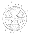
以下、本発明の実施の形態について図を参照して説明する。図1は、本発明の実施形態に係る物流用リールをフランジ側から見た正面図、図2は、同じく側面図である。 Hereinafter, embodiments of the present invention will be described with reference to the drawings. FIG. 1 is a front view of a physical distribution reel according to an embodiment of the present invention as viewed from the flange side, and FIG. 2 is a side view of the same.
例示した物流用リール1は、電子部品実装用のTABテープ(不図示)等を巻き付けて利用されるものであって、該テープの幅に相当する巻き幅を備えた略円筒状のコア2と、該コア2の両端から円盤状に張り出した一対のフランジ3、3とを備えている。コア2は、図2に示すように、その略半分の軸長を有する一対のコア半体20、20からなっており、片側のコア半体20と片側のフランジ3とが、合成樹脂材料の射出成形によって予め一体的に成形される。その成形体同士を2個、突き合わせて、コア半体20、20の突合面を溶着することにより、図示のような物流用リール1が形成される。
The illustrated
フランジ3は、コア2の端面まで塞ぐように形成されており、その中心部分には、実装機等の支軸を取り付けるための軸孔21が、コア2の軸方向に貫通して形成されている。
The
フランジ3における、コア2よりも外方に張り出した部分には、長尺物の巻回状態を目視するため、及びフランジ3の樹脂量を節約して軽量化を図るための目的で、複数箇所の窓開口31が設けられている。例示形態にあっては、各窓開口31は、いずれも、中心角が略60度をなす略扇形に形成されて、4箇所に設けられている。
In the portion of the
そして、これら窓開口31の間に、コア2側から外周側へと延びるスポークが形成されている。例示形態にあっては、中心角が略60度をなす一対の扇形スポーク32、32と、側縁が平行に延びる一対の細幅スポーク33、33とが、それぞれ対称配置となるように形成されている。
And between these
フランジ3には、その剛性を高めるためのリブが形成されている。例示形態におけるリブは、最外周縁に沿って環状に連続する外縁リブ34と、各窓開口31の周縁部を囲む窓縁リブ35である。いずれのリブも略等幅で、フランジ3を外面側に増肉して形成されている。
The
なお、図1において、符号36で示した3個並びの丸孔は、フランジ3の樹脂量を減じるために形成された肉抜き孔であり、軸孔21の近傍に符号22で示した小さい丸孔は、回転状態の検出に利用されるセンサー孔である。また、フランジ3の外面には、コア2の周部の位置に対応して、環状に連続する浅い凹溝37が形成されている。
In FIG. 1, three circular holes indicated by
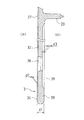
例示の物流用リール1にあっては、見付面積の大きい扇形スポーク32の外面が印刷物等の貼付領域となって、この領域に、例えば図示のような略矩形のラベル4が貼付される。本発明の要部は、この印刷物の貼付領域を構成する扇形スポーク32の断面形状にある。その断面形状を図3に示す。
In the
図3において、フランジ3の最大肉厚がd1である。扇形スポーク32の外面に形成された外縁リブ34及び窓縁リブ35の高さはd2であり、これらのリブを除く外面は、肉抜き孔36の周囲も含めて、ラベル4の貼付を妨げないよう、平坦に形成されている。
In FIG. 3, the maximum thickness of the
一方、扇形スポーク32の内面には、略一定の深さd3の肉盗み部38が形成されている。肉盗み部38は、ラベル4の貼付領域の少なくとも過半にわたって形成されており、例示形態にあっては、図1中に破線で示すように、扇形スポーク32の周部を除く略全体の扇形領域が肉盗み部38となされている。扇形スポーク32の内面側において厚肉のまま残された部分(厚肉部39)は、外面側のリブと協働してフランジ全体の剛性を向上させる作用をなす。
On the other hand, a
このように、印刷物の貼付領域となる扇形スポーク32の外面は、その周縁部のリブを除いて平坦にし、その内面側に肉盗み部38を形成することにより、必要な剛性を確保しつつフランジ3の成形に要する樹脂量を節約することができる。
As described above, the outer surface of the fan-shaped spoke 32 that becomes the pasting area of the printed material is flat except for the peripheral edge rib, and the
なお、上述の実施形態は一例であって、窓開口31の形状や配置、ラベル4の大きさや貼付位置、リブの形状、コア2とフランジ3との成形形態等については、本発明の要旨を逸脱しない範囲で適宜改変可能である。
In addition, the above-mentioned embodiment is an example, Comprising: The shape and arrangement | positioning of the
1 物流用リール
2 コア
3 フランジ
31 窓開口
32 扇形スポーク
34 外縁リブ
35 窓縁リブ
38 肉盗み部
4 ラベル
DESCRIPTION OF
Claims (2)
上記印刷物の貼付領域の外面は平坦に形成される一方、上記印刷物の貼付領域の内面には、フランジ(3)の肉厚を略一定の厚さで減じる肉盗み部(38)が、当該貼付領域の過半にわたって形成されていることを特徴とする物流用リール。 A core (2) around which a long object is wound, and a pair of disc-shaped flanges (3) and (3) provided at both ends of the core (2), and a label ( 4) In an injection molding logistics reel (1) to which other printed matter is affixed,
The outer surface of the printed product sticking region is formed flat, while the flesh stealing portion (38) for reducing the thickness of the flange (3) by a substantially constant thickness is provided on the inner surface of the printed product sticking region. A distribution reel characterized by being formed over a majority of the area.
上記印刷物の貼付領域の外面は平坦に形成される一方、上記印刷物の貼付領域の内面には、フランジ(3)の肉厚を略一定の厚さで減じる肉盗み部(38)が、当該貼付領域の過半にわたって形成されていることを特徴とする物流用リール。 A core (2) around which a long object is wound, and a pair of disc-shaped flanges (3), (3) provided at both ends of the core (2), and at least one flange (3) includes a plurality of A distribution reel (1) made of injection molding in which a window (31) is provided at a location, and a label (4) or other printed matter is pasted on a part of the outer surface of the flange (3) excluding the window opening (31). )
The outer surface of the printed product sticking region is formed flat, while the flesh stealing portion (38) for reducing the thickness of the flange (3) by a substantially constant thickness is provided on the inner surface of the printed product sticking region. A distribution reel characterized by being formed over a majority of the area.
Priority Applications (1)
| Application Number | Priority Date | Filing Date | Title |
|---|---|---|---|
| JP2008176901A JP4884431B2 (en) | 2008-07-07 | 2008-07-07 | Logistics reel |
Applications Claiming Priority (1)
| Application Number | Priority Date | Filing Date | Title |
|---|---|---|---|
| JP2008176901A JP4884431B2 (en) | 2008-07-07 | 2008-07-07 | Logistics reel |
Publications (2)
| Publication Number | Publication Date |
|---|---|
| JP2010013271A true JP2010013271A (en) | 2010-01-21 |
| JP4884431B2 JP4884431B2 (en) | 2012-02-29 |
Family
ID=41699753
Family Applications (1)
| Application Number | Title | Priority Date | Filing Date |
|---|---|---|---|
| JP2008176901A Active JP4884431B2 (en) | 2008-07-07 | 2008-07-07 | Logistics reel |
Country Status (1)
| Country | Link |
|---|---|
| JP (1) | JP4884431B2 (en) |
Cited By (2)
| Publication number | Priority date | Publication date | Assignee | Title |
|---|---|---|---|---|
| JP2012091919A (en) * | 2010-10-28 | 2012-05-17 | Murata Mfg Co Ltd | Tape winding reel and method for manufacturing tape winding reel |
| WO2021125208A1 (en) * | 2019-12-20 | 2021-06-24 | 株式会社フジクラ | Optical fiber winding bobbin |
Citations (2)
| Publication number | Priority date | Publication date | Assignee | Title |
|---|---|---|---|---|
| JPS638266A (en) * | 1986-06-27 | 1988-01-14 | 日本特殊陶業株式会社 | Manufacture of ceramic electronic parts |
| JPH0680314A (en) * | 1991-11-11 | 1994-03-22 | Gold Kogyo Kk | Reel made of synthetic resin |
-
2008
- 2008-07-07 JP JP2008176901A patent/JP4884431B2/en active Active
Patent Citations (2)
| Publication number | Priority date | Publication date | Assignee | Title |
|---|---|---|---|---|
| JPS638266A (en) * | 1986-06-27 | 1988-01-14 | 日本特殊陶業株式会社 | Manufacture of ceramic electronic parts |
| JPH0680314A (en) * | 1991-11-11 | 1994-03-22 | Gold Kogyo Kk | Reel made of synthetic resin |
Cited By (4)
| Publication number | Priority date | Publication date | Assignee | Title |
|---|---|---|---|---|
| JP2012091919A (en) * | 2010-10-28 | 2012-05-17 | Murata Mfg Co Ltd | Tape winding reel and method for manufacturing tape winding reel |
| KR101325554B1 (en) * | 2010-10-28 | 2013-11-06 | 가부시키가이샤 무라타 세이사쿠쇼 | A method of manufacturing a tape winding reel |
| WO2021125208A1 (en) * | 2019-12-20 | 2021-06-24 | 株式会社フジクラ | Optical fiber winding bobbin |
| CN114868059A (en) * | 2019-12-20 | 2022-08-05 | 株式会社藤仓 | Reel for winding optical fiber |
Also Published As
| Publication number | Publication date |
|---|---|
| JP4884431B2 (en) | 2012-02-29 |
Similar Documents
| Publication | Publication Date | Title |
|---|---|---|
| KR101330861B1 (en) | Wound body | |
| JP2509943B2 (en) | Reel assembly | |
| JPS5827586B2 (en) | Physioglycine and other drugs | |
| JP4884431B2 (en) | Logistics reel | |
| CN102148047A (en) | Reel and recording tape cartridge | |
| US20090054219A1 (en) | Spool assembly | |
| JP4884424B2 (en) | Logistics reel | |
| JP4862956B2 (en) | How to take up the tape | |
| KR101467128B1 (en) | Winding core, winding reel and band-winding method | |
| US20090084880A1 (en) | Magnetic tape reel and magnetic tape cartridge | |
| US20130334353A1 (en) | Reel | |
| JP2002251859A (en) | Tape reel | |
| JP2009113857A (en) | Reel for carrier tape of electronic component | |
| US20130206890A1 (en) | Tape guiding member | |
| JP2009073577A (en) | Injection-molded reel for carrier tape | |
| JP5502631B2 (en) | Reel for carrier tape of electronic parts and its half | |
| JP6003267B2 (en) | reel | |
| US20080197231A1 (en) | Tape cartridge | |
| JP2009208895A (en) | Reel for carrier tape for electronic component and its half body | |
| JP6781665B2 (en) | How to wind the carrier tape | |
| JP2007308276A (en) | Reel and method of assembling reel | |
| JP3613499B2 (en) | Reel for magnetic tape cassette | |
| JP2012043512A (en) | Reel | |
| JP2012131576A (en) | Structure for holding articles | |
| JP2009073619A (en) | Reel |
Legal Events
| Date | Code | Title | Description |
|---|---|---|---|
| A621 | Written request for application examination |
Free format text: JAPANESE INTERMEDIATE CODE: A621 Effective date: 20110114 |
|
| RD02 | Notification of acceptance of power of attorney |
Free format text: JAPANESE INTERMEDIATE CODE: A7422 Effective date: 20110114 |
|
| A871 | Explanation of circumstances concerning accelerated examination |
Free format text: JAPANESE INTERMEDIATE CODE: A871 Effective date: 20110826 |
|
| A975 | Report on accelerated examination |
Free format text: JAPANESE INTERMEDIATE CODE: A971005 Effective date: 20110915 |
|
| A131 | Notification of reasons for refusal |
Free format text: JAPANESE INTERMEDIATE CODE: A131 Effective date: 20110927 |
|
| A521 | Request for written amendment filed |
Free format text: JAPANESE INTERMEDIATE CODE: A523 Effective date: 20111109 |
|
| TRDD | Decision of grant or rejection written | ||
| A01 | Written decision to grant a patent or to grant a registration (utility model) |
Free format text: JAPANESE INTERMEDIATE CODE: A01 Effective date: 20111206 |
|
| A01 | Written decision to grant a patent or to grant a registration (utility model) |
Free format text: JAPANESE INTERMEDIATE CODE: A01 |
|
| A61 | First payment of annual fees (during grant procedure) |
Free format text: JAPANESE INTERMEDIATE CODE: A61 Effective date: 20111206 |
|
| FPAY | Renewal fee payment (event date is renewal date of database) |
Free format text: PAYMENT UNTIL: 20141216 Year of fee payment: 3 |
|
| R150 | Certificate of patent or registration of utility model |
Free format text: JAPANESE INTERMEDIATE CODE: R150 Ref document number: 4884431 Country of ref document: JP Free format text: JAPANESE INTERMEDIATE CODE: R150 |
|
| R250 | Receipt of annual fees |
Free format text: JAPANESE INTERMEDIATE CODE: R250 |
|
| R250 | Receipt of annual fees |
Free format text: JAPANESE INTERMEDIATE CODE: R250 |
|
| R250 | Receipt of annual fees |
Free format text: JAPANESE INTERMEDIATE CODE: R250 |
|
| R250 | Receipt of annual fees |
Free format text: JAPANESE INTERMEDIATE CODE: R250 |
|
| R250 | Receipt of annual fees |
Free format text: JAPANESE INTERMEDIATE CODE: R250 |
|
| R250 | Receipt of annual fees |
Free format text: JAPANESE INTERMEDIATE CODE: R250 |
|
| R250 | Receipt of annual fees |
Free format text: JAPANESE INTERMEDIATE CODE: R250 |
|
| R250 | Receipt of annual fees |
Free format text: JAPANESE INTERMEDIATE CODE: R250 |
|
| R250 | Receipt of annual fees |
Free format text: JAPANESE INTERMEDIATE CODE: R250 |
|
| R250 | Receipt of annual fees |
Free format text: JAPANESE INTERMEDIATE CODE: R250 |