JP2010012818A - Engine control unit - Google Patents
Engine control unit Download PDFInfo
- Publication number
- JP2010012818A JP2010012818A JP2008172280A JP2008172280A JP2010012818A JP 2010012818 A JP2010012818 A JP 2010012818A JP 2008172280 A JP2008172280 A JP 2008172280A JP 2008172280 A JP2008172280 A JP 2008172280A JP 2010012818 A JP2010012818 A JP 2010012818A
- Authority
- JP
- Japan
- Prior art keywords
- receiver
- authentication
- registered
- engine control
- theft function
- Prior art date
- Legal status (The legal status is an assumption and is not a legal conclusion. Google has not performed a legal analysis and makes no representation as to the accuracy of the status listed.)
- Granted
Links
Images


Classifications
-
- H—ELECTRICITY
- H04—ELECTRIC COMMUNICATION TECHNIQUE
- H04L—TRANSMISSION OF DIGITAL INFORMATION, e.g. TELEGRAPHIC COMMUNICATION
- H04L9/00—Cryptographic mechanisms or cryptographic arrangements for secret or secure communications; Network security protocols
- H04L9/32—Cryptographic mechanisms or cryptographic arrangements for secret or secure communications; Network security protocols including means for verifying the identity or authority of a user of the system or for message authentication, e.g. authorization, entity authentication, data integrity or data verification, non-repudiation, key authentication or verification of credentials
- H04L9/3271—Cryptographic mechanisms or cryptographic arrangements for secret or secure communications; Network security protocols including means for verifying the identity or authority of a user of the system or for message authentication, e.g. authorization, entity authentication, data integrity or data verification, non-repudiation, key authentication or verification of credentials using challenge-response
Abstract
Description
この発明は、例えば船舶等の移動体に設けられるエンジン制御装置に関し、特に、盗難防止システムに対応したエンジン制御装置に関する。 The present invention relates to an engine control device provided in a moving body such as a ship, and more particularly to an engine control device corresponding to an antitheft system.
従来の盗難防止装置において、受信機(イモビライザ制御部)は、携帯機からのキーIDと受信機にあらかじめ記憶された認証用キーIDとを照合し、両者が一致した場合に、エンジン制御装置(ECU)に対して、エンジンの始動許可信号を出力する。また、エンジン制御装置は、始動許可信号に応じて、エンジンの始動を制御する(例えば、特許文献1参照)。 In a conventional anti-theft device, a receiver (immobilizer control unit) collates a key ID from a portable device with an authentication key ID stored in advance in the receiver, and if they match, the engine control device ( The engine start permission signal is output to the ECU. Further, the engine control device controls the start of the engine according to the start permission signal (see, for example, Patent Document 1).
しかしながら、従来技術には、次のような問題点があった。
特許文献1に示されたエンジン制御装置は、盗難防止機能を有するシステムのみに対応している。すなわち、盗難防止機能を有するシステムと有しないシステムとでは、エンジン制御装置の構成が互いに異なり、それぞれのエンジン制御装置について、専用のプログラムおよびデータが存在している。
However, the prior art has the following problems.
The engine control device disclosed in
したがって、盗難防止機能を必要とする場合には、盗難防止機能を有するシステムに対応したエンジン制御装置が必要となり、盗難防止機能を有しないシステムに対して盗難防止機能を追加する場合には、エンジン制御装置自体を交換するか、またはエンジン制御装置のプログラムを変更する必要がある。
そのため、盗難防止機能を容易に後付けすることができないという問題点があった。
Therefore, when an anti-theft function is required, an engine control device corresponding to a system having an anti-theft function is required. When an anti-theft function is added to a system without an anti-theft function, It is necessary to replace the control device itself or change the program of the engine control device.
Therefore, there was a problem that the anti-theft function could not be easily retrofitted.
この発明は、上記のような課題を解決するためになされたものであって、その目的は、盗難防止機能の有無に関係なく動作するとともに、盗難防止機能を容易に後付けすることができるエンジン制御装置を提供することにある。 The present invention has been made to solve the above-described problems, and an object of the present invention is to control an engine that can operate regardless of the presence or absence of the anti-theft function and can easily be retrofitted with the anti-theft function. To provide an apparatus.
この発明に係るエンジン制御装置は、移動体の利用者が携帯する携帯機に登録されたキーIDと、移動体に設けられた受信機に登録された認証用キーIDとが一致した場合に、携帯機が認証された情報を含む受信機ステータス信号を出力する盗難防止システムに対応し、外部からの起動指令によって起動するエンジン制御装置であって、始動許可信号に応じてエンジンの始動を制御する始動制御手段と、受信機を認証するための認証用受信機IDが登録される記憶手段と、移動体に対する盗難防止機能の有無を判別する盗難防止機能有無判別手段とを備え、盗難防止機能有無判別手段は、記憶手段に認証用受信機IDが登録されていない場合であって、かつ受信機ステータス信号が入力されていない場合に、盗難防止機能を有しないとして始動制御手段に始動許可信号を出力するものである。 When the key ID registered in the portable device carried by the user of the mobile object matches the authentication key ID registered in the receiver provided in the mobile object, An engine control device that corresponds to an anti-theft system that outputs a receiver status signal including authenticated information by a portable device, and that is activated by an external activation command, and controls engine start in response to a start permission signal A start control means, a storage means for registering an authentication receiver ID for authenticating the receiver, and an anti-theft function presence / absence judging means for judging the presence / absence of the anti-theft function for the mobile body, and the presence / absence of the anti-theft function The discriminating means starts when the authentication receiver ID is not registered in the storage means and the receiver status signal is not input, assuming that the anti-theft function is not provided. And it outputs a start permission signal to the control means.
この発明のエンジン制御装置によれば、盗難防止機能有無判別手段は、記憶手段に認証用受信機IDが登録されていない場合であって、かつ受信機ステータス信号が入力されていない場合に、盗難防止機能を有しないとして始動許可信号を出力する。
そのため、盗難防止機能の有無に関係なく動作するとともに、盗難防止機能を容易に後付けすることができるエンジン制御装置を得ることができる。
According to the engine control device of the present invention, the anti-theft function presence / absence determination means is theft when the authentication receiver ID is not registered in the storage means and the receiver status signal is not input. A start permission signal is output because the prevention function is not provided.
Therefore, it is possible to obtain an engine control device that operates regardless of the presence or absence of the anti-theft function and can be easily retrofitted with the anti-theft function.
以下、この発明の各実施の形態について図に基づいて説明するが、各図において同一、または相当する部分については、同一符号を付して説明する。
なお、以下の実施の形態では、エンジン制御装置が設けられる移動体として、例えば船舶を例に挙げて説明するが、これに限定されず、エンジン制御装置は、車両や航空機等の移動体に設けられてもよい。
Hereinafter, embodiments of the present invention will be described with reference to the drawings. In the drawings, the same or corresponding parts will be described with the same reference numerals.
In the following embodiments, a moving body provided with an engine control device will be described using, for example, a ship as an example. However, the present invention is not limited thereto, and the engine control device is provided in a moving body such as a vehicle or an aircraft. May be.
実施の形態1.
図1は、この発明の実施の形態1に係るエンジン制御装置3を含む盗難防止システムを示すブロック図である。
図1において、この盗難防止システムは、船舶の利用者が携帯する携帯機1と、船舶に設けられた受信機2と、船舶に設けられ、エンジン4の動作を制御するエンジン制御装置3とから構成されている。また、受信機2とエンジン制御装置3とは、通信線で互いに接続されている。なお、携帯機1は、エンジン4のキー等である。
FIG. 1 is a block diagram showing an anti-theft system including an
In FIG. 1, this antitheft system includes a
携帯機1には、固有のキーIDが登録されている。
受信機2には、携帯機1を認証するための認証用キーIDと、盗難防止システムに共通のIDであるシステムIDと、固有の受信機IDとが登録されている。
受信機2は、携帯機1のキーIDと認証用キーIDとを比較し、両者が一致した場合に、携帯機1の認証が終了したことを情報として含む受信機ステータス信号を出力する。
A unique key ID is registered in the
In the
The
エンジン制御装置3は、始動制御手段31と、記憶手段32と、盗難防止機能有無判別手段33と、登録通信手段34と、認証通信手段35と、初期化通信手段36とを備えている。
以下、エンジン制御装置3の各手段の機能について説明する。
The
Hereinafter, the function of each means of the
始動制御手段31は、盗難防止機能有無判別手段33または認証通信手段35から出力される始動許可信号に応じてエンジン4の始動を制御する。
記憶手段32には、盗難防止システムに共通のIDであって、受信機2に登録されたシステムIDと同一のシステムIDが登録されている。また、記憶手段32には、受信機2を認証するための認証用受信機IDが登録される。
The start control means 31 controls the start of the
In the storage means 32, an ID common to the anti-theft system and the same system ID as the system ID registered in the
次に、図2および図3を参照しながら、盗難防止機能有無判別手段33の機能について詳細に説明する。
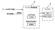
図2は、この発明の実施の形態1に係るエンジン制御装置3を用いた盗難防止機能を有しないシステムを示す構成図である。なお、図2では、エンジン制御装置3のブロック中には、記憶手段32の登録内容のみを図示している。
図2において、エンジン制御装置3には、受信機2が接続されておらず、記憶手段32には、認証用受信機IDが登録されていない。このとき、エンジン制御装置3のユニットは、例えばキーSW等(起動指令)で起動される。
Next, the function of the anti-theft function presence / absence determining means 33 will be described in detail with reference to FIGS.
FIG. 2 is a configuration diagram showing a system that does not have an anti-theft function using the
In FIG. 2, the
図3は、この発明の実施の形態1に係る盗難防止機能を有しないシステムにおける盗難防止機能有無判別手段33の処理を示すシーケンス図である。
図3において、まず、盗難防止機能有無判別手段33は、記憶手段32に認証用受信機IDが登録されているか否かを判定し、認証用受信機IDが登録されていないと判定する。
次に、盗難防止機能有無判別手段33は、受信機ステータス信号が入力されているか否か、すなわち受信機2が接続されているか否かを判定し、受信機ステータス信号が入力されていないと判定する。
FIG. 3 is a sequence diagram showing processing of the anti-theft function presence / absence determining means 33 in the system having no anti-theft function according to
In FIG. 3, the anti-theft function presence / absence determination means 33 first determines whether or not the authentication receiver ID is registered in the storage means 32, and determines that the authentication receiver ID is not registered.
Next, the anti-theft function presence / absence judging means 33 judges whether or not the receiver status signal is inputted, that is, whether or not the
続いて、盗難防止機能有無判別手段33は、記憶手段32に認証用受信機IDが登録されておらず、かつ受信機ステータス信号が入力されていないことから、盗難防止機能を有しないと判別して、始動制御手段31に対して始動許可信号を出力する。
なお、盗難防止機能有無判別手段33は、認証用受信機IDが登録されていると判定した場合、または受信機ステータス信号が入力されていると判定した場合には、始動許可信号を出力しない。
Subsequently, the anti-theft function presence / absence determining means 33 determines that the authentication means does not have an anti-theft function because the authentication receiver ID is not registered in the storage means 32 and no receiver status signal is input. Thus, a start permission signal is output to the start control means 31.
The anti-theft function presence / absence determining means 33 does not output the start permission signal when it is determined that the authentication receiver ID is registered or when it is determined that the receiver status signal is input.
次に、図4および図5を参照しながら、登録通信手段34の機能について詳細に説明する。
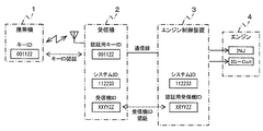
図4は、この発明の実施の形態1に係るエンジン制御装置3を用いた盗難防止機能を有しないシステムに、受信機2および携帯機1を追加した状態を示す構成図である。なお、図4では、エンジン制御装置3のブロック中には、記憶手段32の登録内容のみを図示している。
図4において、エンジン制御装置3には、受信機2が接続されているものの、記憶手段32には、認証用受信機IDが登録されていない。
Next, the function of the
FIG. 4 is a configuration diagram showing a state in which the
In FIG. 4, the
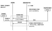
図5は、この発明の実施の形態1に係る盗難防止機能を有しないシステムに、受信機2および携帯機1を追加した状態における受信機2および登録通信手段34の処理を示すシーケンス図である。なお、図5では、携帯機1と受信機2との間の認証は、終了しているものとする。
図5において、まず、登録通信手段34は、記憶手段32に認証用受信機IDが登録されているか否かを判定し、認証用受信機IDが登録されていないと判定する。
FIG. 5 is a sequence diagram showing processing of
In FIG. 5, the
また、受信機2は、携帯機1の認証が終了しているので、受信機ステータス信号を出力している。
次に、登録通信手段34は、所定時間通信を監視し、受信機ステータス信号が入力されているか否か、すなわち受信機2が接続されているか否かを判定し、受信機ステータス信号が入力されていることから、受信機2が接続されていると判定する。
The
Next, the registration communication means 34 monitors the communication for a predetermined time, determines whether or not the receiver status signal is input, that is, whether or not the
続いて、登録通信手段34は、認証用受信機IDを登録するセキュリティモードに移行するために、受信機2に対して、セキュリティモード移行要求信号を出力する。受信機2は、セキュリティモード移行要求信号に対して、チャレンジ信号を出力する。
次に、登録通信手段34は、チャレンジ信号に対して、暗号化されたシステムIDをレスポンスとして出力する。受信機2は、登録通信手段34からのシステムIDと自身のシステムIDとが一致することを確認してセキュリティモードに移行し、セキュリティモード移行結果を登録通信手段34に出力する。
Subsequently, the
Next, the registration communication means 34 outputs the encrypted system ID as a response to the challenge signal. The
続いて、登録通信手段34は、認証用受信機IDを登録するために、受信機2に対して、受信機ID要求信号を出力する。受信機2は、受信機ID要求信号に対して、受信機IDを出力する。
次に、登録通信手段34は、受信機2からの受信機IDを、認証用受信機IDとして記憶手段32に登録する。これにより、エンジン制御装置3と受信機2とがペアリングしたことになる。
また、登録通信手段34は、認証用受信機IDを登録すると、セキュリティモードの終了要求信号を出力し、セキュリティモードを終了する。
Subsequently, the
Next, the
Further, when registering the authentication receiver ID, the registration communication means 34 outputs a security mode end request signal and ends the security mode.
なお、登録通信手段34は、記憶手段32に認証用受信機IDが登録されている場合には、受信機2から受信機ステータス信号が入力されても、認証用受信機IDの再度の登録を行わない。
これにより、認証用受信機IDを誤って更新することを防止することができる。
If the authentication receiver ID is registered in the
As a result, it is possible to prevent the authentication receiver ID from being updated by mistake.
次に、図6および図7を参照しながら、認証通信手段35の機能について詳細に説明する。
図6は、この発明の実施の形態1に係るエンジン制御装置3を用いた盗難防止機能を有するシステムを示す構成図である。なお、図6では、エンジン制御装置3のブロック中には、記憶手段32の登録内容のみを図示している。
図6において、エンジン制御装置3には、受信機2が接続され、記憶手段32には、認証用受信機IDが登録されている。
Next, the function of the
FIG. 6 is a configuration diagram showing a system having an anti-theft function using the
In FIG. 6, the
図7は、この発明の実施の形態1に係る盗難防止機能を有するシステムにおける受信機2および認証通信手段35の処理を示すシーケンス図である。なお、図7では、携帯機1と受信機2との間の認証は、終了しているものとする。
図7において、まず、認証通信手段35は、記憶手段32に認証用受信機IDが登録されているか否かを判定し、認証用受信機IDが登録されていると判定する。
FIG. 7 is a sequence diagram showing processing of
In FIG. 7, the
次に、認証通信手段35は、受信機2を認証するために、受信機2に対して、チャレンジ信号を出力する。受信機2は、チャレンジ信号に対して、暗号化された受信機IDをレスポンスとして出力する。
続いて、認証通信手段35は、受信機2からの受信機IDと認証用受信機IDとを比較し、両者が一致した場合に、始動制御手段31に対して始動許可信号を出力し、受信機2に対して認証結果を出力する。
図7の場合には、受信機IDと認証用受信機IDとが一致しているので、認証通信手段35は、始動許可信号を出力する。
Next, the
Subsequently, the authentication communication means 35 compares the receiver ID from the
In the case of FIG. 7, since the receiver ID and the authentication receiver ID match, the authentication communication means 35 outputs a start permission signal.
次に、図8および図9を参照しながら、初期化通信手段36の機能について詳細に説明する。
図8は、この発明の実施の形態1に係るエンジン制御装置3を用いた盗難防止機能を有するシステムにおいて、認証用受信機IDを消去するための構成を示す構成図である。なお、図8では、エンジン制御装置3のブロック中には、記憶手段32の登録内容のみを図示している。
Next, the function of the
FIG. 8 is a configuration diagram showing a configuration for erasing the authentication receiver ID in the system having the anti-theft function using the
図8において、エンジン制御装置3には、受信機2が接続され、記憶手段32には、認証用受信機IDが登録されている。
また、受信機2からは、専用ツール5を用いて、認証用受信機IDの消去要求信号が入力されている。専用ツール5は、受信機2から認証用受信機IDの消去要求信号を出力させて、エンジン制御装置3の認証用受信機IDを消去する場合に用いられる。
In FIG. 8, the
The
図9は、この発明の実施の形態1に係る盗難防止機能を有するシステムにおいて、認証用受信機IDを消去する初期化通信手段36の処理を示すシーケンス図である。
図9において、まず、受信機2は、認証用受信機IDの消去要求信号を出力し、セキュリティモードへの移行を要求する。初期化通信手段36は、認証用受信機IDの消去要求信号に対して、チャレンジ信号を出力する。
FIG. 9 is a sequence diagram showing processing of the initialization communication means 36 for erasing the authentication receiver ID in the system having the anti-theft function according to
In FIG. 9, first, the
次に、受信機2は、チャレンジ信号に対して、暗号化されたシステムIDをレスポンスとして出力する。初期化通信手段36は、受信機2からのシステムIDと自身のシステムIDとが一致することを確認してセキュリティモードに移行し、セキュリティモード移行結果を受信機2に出力する。
Next, the
続いて、受信機2は、認証用受信機IDを消去するために、初期化通信手段36に対して、受信機ID消去信号を出力する。初期化通信手段36は、受信機ID消去信号に応じて記憶手段32から認証用受信機IDを消去し、認証用受信機IDの消去結果を受信機2に出力する。
Subsequently, the
以下、図10および図11のフローチャートを参照しながら、上記構成のエンジン制御装置3の動作について説明する。
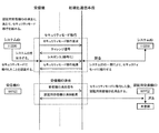
図10は、この発明の実施の形態1に係る盗難防止機能有無判別手段33、登録通信手段34、および認証通信手段35の動作を示すフローチャートである。なお、このフローチャートの処理は、エンジン制御装置3のユニットの起動毎に実行される。
Hereinafter, the operation of the
FIG. 10 is a flowchart showing operations of the anti-theft function presence / absence discriminating means 33, registration communication means 34, and authentication communication means 35 according to
図10において、まず、盗難防止機能有無判別手段33、登録通信手段34、および認証通信手段35は、記憶手段32に認証用受信機IDが登録されているか否かを判定する(ステップS1)。
ステップS1において、認証用受信機IDが登録されていない(すなわち、No)と判定された場合には、盗難防止機能有無判別手段33および登録通信手段34は、受信機ステータス信号が入力されているか否かを判定する(ステップS2)。
In FIG. 10, the anti-theft function presence /
If it is determined in step S1 that the authentication receiver ID is not registered (that is, No), the anti-theft function presence /
一方、ステップS2において、受信機ステータス信号が入力されている(すなわち、Yes)と判定された場合には、登録通信手段34は、受信機2に対して、セキュリティモード移行要求信号を出力し(ステップS3)、セキュリティモードに移行したか否かを判定する(ステップS4)。 On the other hand, if it is determined in step S2 that the receiver status signal has been input (ie, Yes), the registration communication means 34 outputs a security mode transition request signal to the receiver 2 ( Step S3), it is determined whether or not the security mode has been entered (step S4).
ステップS4において、セキュリティモードに移行した(すなわち、Yes)と判定されて場合には、登録通信手段34は、受信機2の受信機IDを認証用受信機IDとして記憶手段32に登録する(ステップS5)。
続いて、登録通信手段34は、セキュリティモードの終了要求信号を出力し(ステップS6)、認証用受信機IDの登録が成功したか否かを判定する(ステップS7)。
If it is determined in step S4 that the mode has shifted to the security mode (that is, Yes), the
Subsequently, the registration communication means 34 outputs a security mode end request signal (step S6), and determines whether or not the registration of the authentication receiver ID is successful (step S7).
ステップS1において、認証用受信機IDが登録されている(すなわち、Yes)と判定された場合、およびステップS7において、認証用受信機IDの登録が成功した(すなわち、Yes)と判定された場合には、認証通信手段35は、受信機2からの受信機IDと認証用受信機IDとを比較して、受信機2が認証されたか否かを判定する(ステップS8)。
When it is determined in step S1 that the authentication receiver ID is registered (ie, Yes), and in step S7, it is determined that registration of the authentication receiver ID is successful (ie, Yes). In step S8, the
ステップS8において、受信機2が認証された(すなわち、Yes)と判定された場合には、認証通信手段35は、始動制御手段31に対して始動許可信号を出力し(ステップS9)、図10の処理を終了する。
一方、ステップS8において、受信機2が認証されていない(すなわち、No)と判定された場合には、認証通信手段35は、エンジン4の始動を禁止して(ステップS10)、図10の処理を終了する。
If it is determined in step S8 that the
On the other hand, if it is determined in step S8 that the
また、ステップS2において、受信機ステータス信号が入力されていない(すなわち、No)と判定された場合、ステップS4において、セキュリティモードに移行していない(すなわち、No)と判定されて場合、およびステップS7において、認証用受信機IDの登録が成功していない(すなわち、No)と判定された場合には、盗難防止機能有無判別手段33または登録通信手段34は、始動制御手段31に対して始動許可信号を出力し(ステップS11)、図10の処理を終了する。
In step S2, if it is determined that the receiver status signal is not input (ie, No), if it is determined in step S4 that the security mode has not been changed (ie, No), and step In S7, when it is determined that the registration of the authentication receiver ID is not successful (that is, No), the anti-theft function presence /
図11は、この発明の実施の形態1に係る初期化通信手段36の動作を示すフローチャートである。
図11において、まず、初期化通信手段36は、受信機2からセキュリティモードへの移行が要求されているか否かを判定する(ステップS21)。
FIG. 11 is a flowchart showing the operation of the initialization communication means 36 according to
In FIG. 11, the initialization communication means 36 first determines whether or not the
ステップS21において、セキュリティモードへの移行が要求されている(すなわち、Yes)と判定された場合には、初期化通信手段36は、セキュリティモードに移行し(ステップS22)、セキュリティモードへの移行が成立したか否かを判定する(ステップS23)。
If it is determined in step S21 that the transition to the security mode is requested (that is, Yes), the
ステップS23において、セキュリティモードへの移行が成立した(すなわち、Yes)と判定された場合には、初期化通信手段36は、受信機2から受信機ID消去信号が入力されているか否かを判定する(ステップS24)。
ステップS24において、受信機ID消去信号が入力されている(すなわち、Yes)と判定された場合には、初期化通信手段36は、記憶手段32から認証用受信機IDを消去する(ステップS25)。
続いて、初期化通信手段36は、セキュリティモードの終了要求信号を出力し(ステップS26)、図11の処理を終了する。
If it is determined in step S23 that the transition to the security mode has been established (that is, Yes), the
If it is determined in step S24 that the receiver ID deletion signal has been input (that is, Yes), the
Subsequently, the initialization communication means 36 outputs a security mode end request signal (step S26), and ends the processing of FIG.
一方、ステップS21において、セキュリティモードへの移行が要求されていない(すなわち、No)と判定された場合、ステップS23において、セキュリティモードへの移行が成立していない(すなわち、No)と判定された場合、およびステップS24において、受信機ID消去信号が入力されていない(すなわち、No)と判定された場合には、そのまま図11の処理を終了する。 On the other hand, if it is determined in step S21 that the transition to the security mode is not requested (that is, No), it is determined in step S23 that the transition to the security mode is not established (that is, No). If it is determined in step S24 that the receiver ID erasure signal has not been input (ie, No), the processing in FIG.
この発明の実施の形態1に係るエンジン制御装置3によれば、盗難防止機能有無判別手段33は、記憶手段32に認証用受信機IDが登録されていない場合であって、かつ受信機2から受信機ステータス信号が入力されていない場合に、盗難防止機能を有しないと判別して、始動制御手段31に対して始動許可信号を出力する。
そのため、盗難防止機能の有無に関係なく動作するとともに、盗難防止機能を用意に後付けすることができる。
また、盗難防止機能の有無に関係のない共通のエンジン制御装置3とすることにより、船舶へのエンジン制御装置3の取り付け作業において混乱を招く可能性が低減され、作業効率を向上させることができる。
According to the
Therefore, it can operate regardless of the presence or absence of the anti-theft function and can be retrofitted with the anti-theft function.
Moreover, by using the common
また、登録通信手段34は、盗難防止機能を有しないシステムに受信機2および携帯機1を追加した場合に、盗難防止システムに共通のIDとして受信機2および記憶手段32に登録されたシステムIDが互いに一致することを確認した上で、受信機2の受信機IDを認証用受信機IDとして記憶手段32に登録している。
従来の盗難防止システムでは、初回電源投入時の受信機とエンジン制御装置との間の認証に必要な情報の登録において、装置間のデータ照合を行わず、通信相手が正しいかどうかを確認しないので、通信タイミングが一致した場合には、他の装置の誤った情報が登録される恐れがあるという問題点があった。
この発明の実施の形態1に係る登録通信手段34では、受信機2とエンジン制御装置3とのシステムIDが互いに一致することを確認しているので、誤った通信による認証用受信機IDの誤登録を防止することができる。
The registered communication means 34 is a system ID registered in the
In the conventional anti-theft system, data registration between devices is not performed in the registration of information required for authentication between the receiver and the engine control device when the power is turned on for the first time. When the communication timings coincide with each other, there is a problem that erroneous information of other devices may be registered.
In the registered communication means 34 according to the first embodiment of the present invention, it is confirmed that the system IDs of the
また、初期化通信手段36は、専用ツール5を用いて受信機2から出力された認証用受信機IDの消去要求信号が入力された場合に、盗難防止システムに共通のIDとして受信機2および記憶手段32に登録されたシステムIDが互いに一致することを確認した上で、記憶手段32から認証用受信機IDを消去している。
そのため、認証用受信機IDを誤って消去することを防止することができる。
また、船舶の利用者による携帯機1の紛失等によって受信機2が利用できなくなった場合であっても、速やかに受信機2を交換することができる。
The initialization communication means 36 receives the
Therefore, it is possible to prevent the authentication receiver ID from being deleted by mistake.
Further, even when the
実施の形態2.
図12は、この発明の実施の形態2に係るエンジン制御装置3A〜3Cを用いた盗難防止機能を有するシステムを示す構成図である。なお、図12では、エンジン制御装置3A〜3Cのブロック中には、記憶手段32の登録内容のみを図示している。
図12において、受信機2には、3台のエンジン制御装置3A〜3Cが接続されている。エンジン制御装置3A〜3Cの構成は、前述した実施の形態1と同様であり、その説明は省略する。なお、受信機2に接続されるエンジン制御装置は、3台に限られず、2台であってもよいし、4台以上であってもよい。
FIG. 12 is a configuration diagram showing a system having an anti-theft function using the engine control devices 3A to 3C according to the second embodiment of the present invention. In FIG. 12, only the registered contents of the storage means 32 are shown in the blocks of the engine control devices 3A to 3C.
In FIG. 12, the
それぞれのエンジン制御装置3A〜3Cの登録通信手段34は、上記実施の形態1で示したように、受信機2とエンジン制御装置3A〜3CとのシステムIDが互いに一致することを確認した上で、受信機2の受信機IDを認証用受信機IDとして登録している。
また、それぞれのエンジン制御装置3A〜3Cの認証通信手段35は、受信機2の受信機IDとエンジン制御装置3A〜3Cの記憶手段32に登録された認証用受信機IDとが互いに一致する場合に、始動制御手段31に対して始動許可信号を出力する。
The registration communication means 34 of each of the engine control devices 3A to 3C confirms that the system IDs of the
Further, the authentication communication means 35 of each engine control device 3A to 3C has a case where the receiver ID of the
この発明の実施の形態2に係るエンジン制御装置3A〜3Cによれば、例えば船舶等複数のエンジン4を有する移動体について、1台の携帯機1および受信機2で複数のエンジン4を制御することができる盗難防止システムを構築することができる。
According to the engine control devices 3A to 3C according to the second embodiment of the present invention, for example, a mobile device having a plurality of
1 携帯機、2 受信機、3、3A〜3C エンジン制御装置、4 エンジン、31 始動制御手段、32 記憶手段、33 盗難防止機能有無判別手段、34 登録通信手段、35 認証通信手段、36 初期化通信手段。
DESCRIPTION OF
Claims (6)
始動許可信号に応じてエンジンの始動を制御する始動制御手段と、
前記受信機を認証するための認証用受信機IDが登録される記憶手段と、
前記移動体に対する盗難防止機能の有無を判別する盗難防止機能有無判別手段と、を備え、
前記盗難防止機能有無判別手段は、前記記憶手段に前記認証用受信機IDが登録されていない場合であって、かつ前記受信機ステータス信号が入力されていない場合に、前記盗難防止機能を有しないとして、前記始動制御手段に前記始動許可信号を出力することを特徴とするエンジン制御装置。 Information that the portable device is authenticated when the key ID registered in the portable device carried by the user of the mobile object matches the authentication key ID registered in the receiver provided in the mobile object An anti-theft system that outputs a receiver status signal including an engine control device that is activated by an external activation command,
Start control means for controlling start of the engine in response to a start permission signal;
Storage means for registering an authentication receiver ID for authenticating the receiver;
An anti-theft function presence / absence determining means for determining the presence / absence of an anti-theft function for the mobile body,
The anti-theft function determination means does not have the anti-theft function when the authentication receiver ID is not registered in the storage means and the receiver status signal is not input. The engine control device outputs the start permission signal to the start control means.
前記登録通信手段は、前記記憶手段に前記認証用受信機IDが登録されていない場合であって、かつ前記受信機ステータス信号が入力された場合に、前記盗難防止システムに共通のIDとして前記受信機および前記記憶手段にそれぞれ登録されたシステムIDが互いに一致することを確認した上で、前記受信機に登録された受信機IDを前記認証用受信機IDとして登録することを特徴とする請求項1に記載のエンジン制御装置。 A registration communication unit for registering the authentication receiver ID in the storage unit;
The registration communication unit receives the reception ID as a common ID for the anti-theft system when the authentication receiver ID is not registered in the storage unit and the receiver status signal is input. The receiver ID registered in the receiver is registered as the authentication receiver ID after confirming that the system IDs registered in the receiver and the storage means match each other. The engine control apparatus according to 1.
前記認証通信手段は、前記記憶手段に前記認証用受信機IDが登録されている場合であって、かつ前記受信機による前記携帯機の認証が終了している場合に、前記受信機に登録された受信機IDと前記認証用受信機IDとを比較し、両者が一致したときに、前記始動許可信号を出力することを特徴とする請求項1から請求項3までの何れか1項に記載のエンジン制御装置。 An authentication communication means for authenticating the receiver;
The authentication communication means is registered in the receiver when the authentication receiver ID is registered in the storage means, and when authentication of the portable device by the receiver has been completed. 4. The start permission signal is output when the receiver ID is compared with the authentication receiver ID, and the two match, and the start permission signal is output. 5. Engine control device.
前記初期化通信手段は、前記受信機から前記認証用受信機IDの消去要求信号が入力された場合に、前記盗難防止システムに共通のIDとして前記受信機および前記記憶手段にそれぞれ登録されたシステムIDが互いに一致することを確認した上で、前記認証用受信機IDを消去することを特徴とする請求項1から請求項4までの何れか1項に記載のエンジン制御装置。 An initialization communication means for erasing the authentication receiver ID registered in the storage means;
The initialization communication means is a system registered in the receiver and the storage means as an ID common to the anti-theft system when an erasure request signal for the authentication receiver ID is input from the receiver. The engine control apparatus according to any one of claims 1 to 4, wherein the authentication receiver ID is deleted after confirming that the IDs match each other.
Priority Applications (2)
| Application Number | Priority Date | Filing Date | Title |
|---|---|---|---|
| JP2008172280A JP4777396B2 (en) | 2008-07-01 | 2008-07-01 | Engine control device |
| US12/347,718 US8730006B2 (en) | 2008-07-01 | 2008-12-31 | Engine control unit |
Applications Claiming Priority (1)
| Application Number | Priority Date | Filing Date | Title |
|---|---|---|---|
| JP2008172280A JP4777396B2 (en) | 2008-07-01 | 2008-07-01 | Engine control device |
Publications (2)
| Publication Number | Publication Date |
|---|---|
| JP2010012818A true JP2010012818A (en) | 2010-01-21 |
| JP4777396B2 JP4777396B2 (en) | 2011-09-21 |
Family
ID=41465367
Family Applications (1)
| Application Number | Title | Priority Date | Filing Date |
|---|---|---|---|
| JP2008172280A Active JP4777396B2 (en) | 2008-07-01 | 2008-07-01 | Engine control device |
Country Status (2)
| Country | Link |
|---|---|
| US (1) | US8730006B2 (en) |
| JP (1) | JP4777396B2 (en) |
Cited By (3)
| Publication number | Priority date | Publication date | Assignee | Title |
|---|---|---|---|---|
| JP2013208919A (en) * | 2012-03-30 | 2013-10-10 | Kubota Corp | Working machine, anti-theft system for the working machine, and program for control device for the working machine |
| JP2014054181A (en) * | 2013-10-22 | 2014-03-20 | Mitsubishi Motors Corp | Electric vehicle control device |
| JP2014237445A (en) * | 2014-09-11 | 2014-12-18 | 三菱自動車工業株式会社 | Control device for electric vehicle |
Families Citing this family (2)
| Publication number | Priority date | Publication date | Assignee | Title |
|---|---|---|---|---|
| JP5144947B2 (en) * | 2006-07-07 | 2013-02-13 | ヤマハ発動機株式会社 | Vehicle anti-theft system and vehicle equipped with anti-theft system |
| CN113596627B (en) * | 2021-09-29 | 2022-02-22 | 中兴通讯股份有限公司 | Authorization control method and device for power equipment, electronic equipment and storage medium |
Citations (4)
| Publication number | Priority date | Publication date | Assignee | Title |
|---|---|---|---|---|
| JPH0914109A (en) * | 1995-07-03 | 1997-01-14 | Calsonic Corp | Engine erroneous starting preventive device |
| JPH10102862A (en) * | 1996-09-27 | 1998-04-21 | Mazda Motor Corp | Burglar preventing device for vehicle |
| JP3511700B2 (en) * | 1994-11-30 | 2004-03-29 | 株式会社デンソー | Anti-theft devices for vehicles |
| JP2007290618A (en) * | 2006-04-26 | 2007-11-08 | Yanmar Co Ltd | Engine control system and working machine |
Family Cites Families (9)
| Publication number | Priority date | Publication date | Assignee | Title |
|---|---|---|---|---|
| US6008722A (en) * | 1994-08-02 | 1999-12-28 | Mazda Motor Corporation | Anti-vehicle-thief apparatus and code setting method of the apparatus |
| US5708307A (en) * | 1994-11-02 | 1998-01-13 | Nissan Motor Co., Ltd. | Anti-theft car protection system |
| US20030076957A1 (en) * | 2001-10-18 | 2003-04-24 | Nadarajah Asokan | Method, system and computer program product for integrity-protected storage in a personal communication device |
| US6842106B2 (en) * | 2002-10-04 | 2005-01-11 | Battelle Memorial Institute | Challenged-based tag authentication model |
| JP2004218538A (en) * | 2003-01-15 | 2004-08-05 | Fujitsu Ten Ltd | Remote starting devise for vehicle |
| JP4172297B2 (en) | 2003-03-17 | 2008-10-29 | 三菱電機株式会社 | Anti-theft device for vehicles, etc. |
| JP4144741B2 (en) | 2003-05-27 | 2008-09-03 | 三菱電機株式会社 | Vehicle anti-theft device |
| JP2006027551A (en) * | 2004-07-21 | 2006-02-02 | Yazaki Corp | On-vehicle ecu monitor |
| JP4570974B2 (en) * | 2005-02-04 | 2010-10-27 | 富士通テン株式会社 | Start control device and start control method |
-
2008
- 2008-07-01 JP JP2008172280A patent/JP4777396B2/en active Active
- 2008-12-31 US US12/347,718 patent/US8730006B2/en active Active
Patent Citations (4)
| Publication number | Priority date | Publication date | Assignee | Title |
|---|---|---|---|---|
| JP3511700B2 (en) * | 1994-11-30 | 2004-03-29 | 株式会社デンソー | Anti-theft devices for vehicles |
| JPH0914109A (en) * | 1995-07-03 | 1997-01-14 | Calsonic Corp | Engine erroneous starting preventive device |
| JPH10102862A (en) * | 1996-09-27 | 1998-04-21 | Mazda Motor Corp | Burglar preventing device for vehicle |
| JP2007290618A (en) * | 2006-04-26 | 2007-11-08 | Yanmar Co Ltd | Engine control system and working machine |
Cited By (3)
| Publication number | Priority date | Publication date | Assignee | Title |
|---|---|---|---|---|
| JP2013208919A (en) * | 2012-03-30 | 2013-10-10 | Kubota Corp | Working machine, anti-theft system for the working machine, and program for control device for the working machine |
| JP2014054181A (en) * | 2013-10-22 | 2014-03-20 | Mitsubishi Motors Corp | Electric vehicle control device |
| JP2014237445A (en) * | 2014-09-11 | 2014-12-18 | 三菱自動車工業株式会社 | Control device for electric vehicle |
Also Published As
| Publication number | Publication date |
|---|---|
| JP4777396B2 (en) | 2011-09-21 |
| US8730006B2 (en) | 2014-05-20 |
| US20100005507A1 (en) | 2010-01-07 |
Similar Documents
| Publication | Publication Date | Title |
|---|---|---|
| JP4777396B2 (en) | Engine control device | |
| JP2007255075A (en) | Radio communication system and method, as well as portable radio communication device and method | |
| JP5599759B2 (en) | Start control device | |
| KR101523760B1 (en) | Immobilizer apparatus using random pulse generation and authentication method thereof | |
| JP2008190244A (en) | Electronic key system, on-vehicle device for electronic key system and portable machine for electronic key system | |
| KR20170075986A (en) | Smart key system applied double security and double security method for vehicle using the same | |
| JP2009019536A (en) | Control device and method | |
| KR20110140023A (en) | System and method for controlling smart key using obd ii | |
| KR20160022039A (en) | Smart key control system and method for vehicle | |
| JP6274849B2 (en) | Vehicle control system | |
| JP3974612B2 (en) | Mobile device registration system | |
| JP2006117086A (en) | Antitheft device for vehicle | |
| JP2007231654A (en) | Cellular phone terminal unit and electronic key device | |
| JP2010112053A (en) | Vehicle authentication control device | |
| JP2006281883A (en) | Vehicular electronic control device, and vehicle service center | |
| JP2022178229A (en) | Vehicle control device, vehicle, vehicle control method and program | |
| JP2018204183A (en) | Vehicle entry system | |
| JP4343782B2 (en) | On-vehicle control device, portable device detection method, and program | |
| JP5647030B2 (en) | Electronic key registration system | |
| JP6060761B2 (en) | Vehicle antitheft device | |
| JP2006018545A (en) | Usb module | |
| JP2014187632A (en) | Information terminal, unlocking method and unlocking program | |
| JP2010254172A (en) | Antitheft system | |
| JP2005336911A (en) | Vehicle control system and on-vehicle controller and portable machine used in it | |
| JP4581718B2 (en) | Immobilizer function setting device and immobilizer function setting method |
Legal Events
| Date | Code | Title | Description |
|---|---|---|---|
| A977 | Report on retrieval |
Free format text: JAPANESE INTERMEDIATE CODE: A971007 Effective date: 20100428 |
|
| A131 | Notification of reasons for refusal |
Free format text: JAPANESE INTERMEDIATE CODE: A131 Effective date: 20100511 |
|
| A02 | Decision of refusal |
Free format text: JAPANESE INTERMEDIATE CODE: A02 Effective date: 20110104 |
|
| A521 | Request for written amendment filed |
Free format text: JAPANESE INTERMEDIATE CODE: A523 Effective date: 20110401 |
|
| A911 | Transfer to examiner for re-examination before appeal (zenchi) |
Free format text: JAPANESE INTERMEDIATE CODE: A911 Effective date: 20110411 |
|
| TRDD | Decision of grant or rejection written | ||
| A01 | Written decision to grant a patent or to grant a registration (utility model) |
Free format text: JAPANESE INTERMEDIATE CODE: A01 Effective date: 20110628 |
|
| A01 | Written decision to grant a patent or to grant a registration (utility model) |
Free format text: JAPANESE INTERMEDIATE CODE: A01 |
|
| A61 | First payment of annual fees (during grant procedure) |
Free format text: JAPANESE INTERMEDIATE CODE: A61 Effective date: 20110629 |
|
| R150 | Certificate of patent or registration of utility model |
Ref document number: 4777396 Country of ref document: JP Free format text: JAPANESE INTERMEDIATE CODE: R150 Free format text: JAPANESE INTERMEDIATE CODE: R150 |
|
| FPAY | Renewal fee payment (event date is renewal date of database) |
Free format text: PAYMENT UNTIL: 20140708 Year of fee payment: 3 |
|
| R250 | Receipt of annual fees |
Free format text: JAPANESE INTERMEDIATE CODE: R250 |
|
| R250 | Receipt of annual fees |
Free format text: JAPANESE INTERMEDIATE CODE: R250 |
|
| R250 | Receipt of annual fees |
Free format text: JAPANESE INTERMEDIATE CODE: R250 |
|
| R250 | Receipt of annual fees |
Free format text: JAPANESE INTERMEDIATE CODE: R250 |
|
| R250 | Receipt of annual fees |
Free format text: JAPANESE INTERMEDIATE CODE: R250 |
|
| R250 | Receipt of annual fees |
Free format text: JAPANESE INTERMEDIATE CODE: R250 |
|
| R250 | Receipt of annual fees |
Free format text: JAPANESE INTERMEDIATE CODE: R250 |
|
| R250 | Receipt of annual fees |
Free format text: JAPANESE INTERMEDIATE CODE: R250 |
|
| R250 | Receipt of annual fees |
Free format text: JAPANESE INTERMEDIATE CODE: R250 |