JP2010011967A - Game machine - Google Patents
Game machine Download PDFInfo
- Publication number
- JP2010011967A JP2010011967A JP2008173643A JP2008173643A JP2010011967A JP 2010011967 A JP2010011967 A JP 2010011967A JP 2008173643 A JP2008173643 A JP 2008173643A JP 2008173643 A JP2008173643 A JP 2008173643A JP 2010011967 A JP2010011967 A JP 2010011967A
- Authority
- JP
- Japan
- Prior art keywords
- effect
- symbol
- state
- big hit
- variable display
- Prior art date
- Legal status (The legal status is an assumption and is not a legal conclusion. Google has not performed a legal analysis and makes no representation as to the accuracy of the status listed.)
- Granted
Links
Images


Abstract
Description
本発明は、各々を識別可能な複数種類の識別情報の可変表示を行い表示結果を導出表示する可変表示装置を備え、該可変表示装置に特定表示結果が導出表示されたときに遊技者にとって有利な特定遊技状態に移行させるとともに、可変表示装置に特定表示結果のうち特別表示結果が導出表示されたときに特定遊技状態が終了したのちに通常状態であるときに比べて識別情報の可変表示の表示結果が特定表示結果となりやすい特別遊技状態に移行させるパチンコ遊技機やスロット機等の遊技機に関する。 The present invention includes a variable display device that variably displays a plurality of types of identification information that can be distinguished from each other and derives and displays a display result, and is advantageous for a player when a specific display result is derived and displayed on the variable display device. When the special display result among the specific display results is derived and displayed on the variable display device, the variable display device can display the identification information in a variable manner compared to the normal state after the specific gaming state is ended. The present invention relates to a gaming machine such as a pachinko gaming machine or a slot machine that shifts to a special gaming state in which a display result tends to be a specific display result.
遊技機として、遊技球などの遊技媒体を発射装置によって遊技領域に発射し、遊技領域に設けられている入賞口などの入賞領域に遊技媒体が入賞すると、所定個の賞球が遊技者に払い出されるものがある。さらに、識別情報を可変表示(「変動」ともいう。)可能な可変表示装置が設けられ、可変表示装置において識別情報の可変表示の表示結果が特定表示結果となった場合に遊技者にとって有利な特定遊技状態に制御可能になるように構成されたものがある。 As a gaming machine, a game medium such as a game ball is launched into a game area by a launching device, and when a game medium wins a prize area such as a prize opening provided in the game area, a predetermined number of prize balls are paid out to the player. There is something to be done. Furthermore, a variable display device capable of variably displaying the identification information (also referred to as “fluctuation”) is provided, which is advantageous to the player when the display result of the variable display of the identification information in the variable display device becomes a specific display result. Some are configured to be controllable to a specific gaming state.
特定遊技状態とは、所定の遊技価値が付与された遊技者にとって有利な状態を意味する。具体的には、特定遊技状態は、例えば特別可変入賞装置の状態を打球が入賞しやすい遊技者にとって有利な状態(大当り遊技状態)、遊技者にとって有利な状態になるための権利が発生した状態、景品遊技媒体払出の条件が成立しやすくなる状態などの所定の遊技価値が付与された状態である。 The specific game state means a state advantageous for a player who is given a predetermined game value. Specifically, the specific game state is, for example, a state in which a special variable winning device is advantageous for a player who is likely to win a ball (a big hit game state), or a state in which a right to be advantageous for a player has occurred. In this state, a predetermined game value such as a state where conditions for paying out premium game media are easily established is given.
そのような遊技機では、識別情報としての図柄を表示する可変表示装置の表示結果があらかじめ定められた特定の表示態様の組合せ(特定表示結果)になることを、通常、「大当り」という。大当りが発生すると、例えば、大入賞口が所定回数開放して打球が入賞しやすい大当り遊技状態に移行する。そして、各開放期間において、所定個(例えば10個)の大入賞口への入賞があると大入賞口は閉成する。そして、大入賞口の開放回数は、所定回数(例えば15ラウンド)に固定されている。なお、各開放について開放時間(例えば29.5秒)が決められ、入賞数が所定個に達しなくても開放時間が経過すると大入賞口は閉成する。また、大入賞口が閉成した時点で所定の条件(例えば、大入賞口内に設けられているVゾーンへの入賞)が成立していない場合には、大当り遊技状態は終了する。 In such a gaming machine, the fact that the display result of the variable display device that displays the symbol as identification information is a combination of specific display modes (specific display result) determined in advance is generally referred to as “big hit”. When the big hit occurs, for example, the big winning opening is opened a predetermined number of times, and the game shifts to a big hit gaming state where the hit ball is easy to win. And in each open period, if there is a prize for a predetermined number (for example, 10) of the big prize opening, the big prize opening is closed. And the number of times the special winning opening is opened is fixed to a predetermined number (for example, 15 rounds). An opening time (for example, 29.5 seconds) is determined for each opening, and even if the number of winnings does not reach a predetermined number, the big winning opening is closed when the opening time elapses. Further, when a predetermined condition (for example, winning in the V zone provided in the big prize opening) is not established at the time when the big prize opening is closed, the big hit gaming state is ended.
また、遊技機には、可変表示装置において識別情報の可変表示の表示結果が特定表示結果のうちの特別な特定表示結果(特別表示結果。例えば、左中右が同じ奇数図柄で揃った確変図柄。)となるなどの特別の条件が成立すると、以後、大当りが発生する確率が高くなる高確率状態(確変状態ともいう。)に移行するように構成されたものもある。 In addition, in the gaming machine, the display result of the variable display of the identification information in the variable display device is a special specific display result of the specific display results (special display result. In some cases, when a special condition such as “.
また、そのような遊技機では、識別情報の可変表示中にキャラクタを登場させ、登場させたキャラクタがバトルを行う演出態様のバトル演出を行うように構成されたものがある。例えば、特許文献1に記載された遊技機では、確変状態に移行するとバトルモードに移行し、以降の識別情報の可変表示中に味方と敵のキャラクタがバトルを行うバトル演出を行う。そして、味方のキャラクタがバトルに勝利すれば大当りとなったり、バトルの決着がつかなければ確変状態が継続する態様の演出を実行する。また、味方のキャラクタがバトルに敗北すると、確変状態を終了し時短状態に移行する態様の演出を実行する。
In addition, in such gaming machines, there is one configured to perform a battle effect in an effect mode in which a character appears during variable display of identification information, and the introduced character performs a battle. For example, in the gaming machine described in
しかし、特許文献1に記載された遊技機では、可変表示中の識別情報にかかわりなく、味方のキャラクタがバトルに敗北した場合には確変状態が終了され時短状態に移行されているので、遊技者はバトル演出の演出結果に注目せざるをえず、遊技者に対して識別情報の可変表示内容に関心を向けさせることはできない。そのため、識別情報の可変表示中における遊技に対する興趣を十分に向上できるとはかぎらない。
However, in the gaming machine described in
そこで、本発明は、識別情報の可変表示中にバトル演出を実行可能な遊技機において、バトル演出の結果だけでなく識別情報の可変表示内容に対しても遊技者に関心を向けさせることができ、遊技に対する興趣を向上させることができるようにすることを目的とする。 Therefore, the present invention can make a player pay attention to not only the result of the battle effect but also the variable display contents of the identification information in the gaming machine capable of executing the battle effect during the variable display of the identification information. The purpose is to improve the interest in games.
本発明による遊技機は、各々を識別可能な複数種類の識別情報(例えば、演出図柄)の可変表示を行い表示結果を導出表示する可変表示装置(例えば、演出表示装置9)を備え、該可変表示装置に特定表示結果(例えば、大当り図柄)が導出表示されたときに遊技者にとって有利な特定遊技状態(例えば、大当り遊技状態)に移行させるとともに、所定条件が成立(例えば、15R確変大当り、7R確変大当りまたは突然確変大当りと決定)したときに通常状態であるときに比べて遊技者にとって有利な特別遊技状態(例えば、確変状態)に移行させる遊技機(例えば、パチンコ遊技機、スロット機)であって、特定遊技状態に移行させるか否かを表示結果の導出表示以前に決定する事前決定手段(例えば、遊技制御用マイクロコンピュータ560におけるステップS61を実行する部分)と、特別遊技状態において事前決定手段により特定遊技状態に移行させる旨が決定されたときに、移行される特定遊技状態が終了したのちに特別遊技状態を継続させるか否かを決定する継続決定手段(例えば、遊技制御用マイクロコンピュータ560におけるステップS72,S73を実行する部分。具体的には、大当り種別を、突然確変大当り、15R確変大当りまたは7R確変大当りと決定することで確変状態を継続させると決定するか、突然時短大当りと決定することで確変状態を終了させると決定する。)と、事前決定手段および継続決定手段の決定結果にもとづいて、識別情報の可変表示を実行するとともに表示結果を導出表示する可変表示実行手段(例えば、演出制御用マイクロコンピュータ100におけるステップS519〜S522,S840〜S858,S872を実行する部分)とを備え、可変表示実行手段は、特定遊技状態において事前決定手段により特定遊技状態に移行される旨が決定されたときに、識別情報の可変表示において所定のリーチ状態を発生させた後、継続決定手段の決定結果を報知するための継続報知演出(例えば、図49〜図54に示すバトル演出)を実行する継続報知演出実行手段(例えば、演出制御用マイクロコンピュータ100において、バトルPA5−1〜バトルPA5−1の変動パターンに従ってステップS519〜S522,S840〜S858,S872を実行することによって、演出図柄の変動表示中にバトル演出を実行する部分)と、継続決定手段の決定結果にもとづいて、所定のリーチ状態を構成する識別情報(例えば、左右の演出図柄)を複数種類の識別情報の中から選択して決定するリーチ識別情報決定手段(例えば、演出制御用マイクロコンピュータ100におけるステップS508Bを実行する部分)とを含み、リーチ識別情報決定手段は、継続決定手段が特別遊技状態を継続させると決定したときと継続させないと決定したときとで、所定のリーチ状態を構成する識別情報を選択する確率を異ならせて決定するとともに(例えば、演出制御用マイクロコンピュータ100は、ステップS508Bにおいて、大当り種別に応じて図39に示す図柄の振分が異なるいずれかのバトル時リーチ停止図柄決定テーブル168A〜168Dを用いてリーチ図柄を決定する。)、継続決定手段が特別遊技状態を継続させると決定したことを条件に、所定のリーチ状態を構成する識別情報として特定識別情報(例えば、バトルに勝利しやすい図柄「7」)を決定する(例えば、演出制御用マイクロコンピュータ100は、ステップS508Bにおいて、図39に示す15R確変大当り用のバトル時リーチ停止図柄決定テーブル168Aを用いて、高い割合でリーチ図柄として「7」を決定する。)ことを特徴とする。
A gaming machine according to the present invention includes a variable display device (for example, an effect display device 9) that variably displays a plurality of types of identification information (for example, effect symbols) that can be identified, and that displays and displays a display result. When a specific display result (for example, a big hit symbol) is derived and displayed on the display device, it is shifted to a specific gaming state (for example, a big hit gaming state) advantageous to the player, and a predetermined condition is satisfied (for example, 15R probability change big hit, A gaming machine (for example, a pachinko gaming machine or a slot machine) that shifts to a special gaming state (for example, a probability variation state) that is more advantageous to the player than when it is in a normal state when it is determined as a 7R probability variation big hit or sudden probability variation big hit) A pre-determining means (for example, a game control microcomputer) that determines whether or not to shift to a specific gaming state before derivation display of the display result 60) and the special game state is continued after the specific game state to be transferred is finished when it is determined in advance in the special game state that the transition to the specific game state has been made. Continuation determining means for determining whether or not (for example, a part for executing steps S72 and S73 in the
遊技機は、特別遊技状態において事前決定手段により特定遊技状態に移行させる旨が決定されたときに、特定遊技状態に制御する期間を少なくとも第1期間(例えば、7ラウンド)と該第1期間より長い第2期間(例えば、15ラウンド)のうちから決定する期間決定手段(例えば、遊技制御用マイクロコンピュータ560におけるステップS72,S73を実行する部分。具体的には、大当り種別を、7ラウンド大当りの7R確変大当りと決定したり、15ラウンド大当りの15R確変大当りと決定する。)をさらに備え、リーチ識別情報決定手段は、所定のリーチ状態を構成する識別情報として特定識別情報(例えば、バトルに勝利しやすい図柄「7」)を決定するときに、期間決定手段が特定遊技状態に第2期間制御すると決定している割合が高くなるような確率で、所定のリーチ状態を構成する識別情報を選択して決定する(例えば、演出制御用マイクロコンピュータ100は、ステップS508Bにおいて、図39に示すように、7R確変大当り用のバトル時リーチ停止図柄決定テーブル168Bと比較して、図柄「7」に対する割振が大きい15R確変大当り用のバトル時リーチ停止図柄決定テーブル168Aを用いて、高い割合でリーチ図柄として「7」を決定する。)ように構成されていてもよい。
When the gaming machine is determined to shift to the specific gaming state by the predetermining means in the special gaming state, the period for controlling to the specific gaming state is at least the first period (for example, 7 rounds) and the first period. Period determining means (for example, a part for executing steps S72 and S73 in the
遊技機は、特別遊技状態において事前決定手段により特定遊技状態に移行させる旨が決定されたときに、特定遊技状態に制御する期間を少なくとも第1期間(例えば、2ラウンド)と該第1期間より長い第2期間(例えば、7ラウンドまたは15ラウンド)のうちから決定する期間決定手段(例えば、遊技制御用マイクロコンピュータ560におけるステップS72,S73を実行する部分。具体的には、大当り種別を、2ラウンド大当りの突然確変大当りまたは突然時短大当りと決定したり、7ラウンド大当りの7R確変大当りと決定したり、15ラウンド大当りの15R確変大当りと決定する。)をさらに備え、リーチ識別情報決定手段は、所定のリーチ状態を構成する識別情報として特定識別情報以外の識別情報を決定するときに、継続決定手段が特別遊技状態を継続させないと決定している割合と、継続決定手段が特別遊技状態を継続させると決定し、かつ期間決定手段が特定遊技状態に第1期間制御すると決定している割合と、が識別情報の種類(例えば、「7」以外の奇数図柄または偶数図柄)に応じて異なるような確率で、所定のリーチ状態を構成する識別情報を選択して決定する(例えば、演出制御用マイクロコンピュータ100は、ステップS508Bにおいて、図39に示すように、突然確変大当り用のバトル時リーチ停止図柄決定テーブル168Cと比較して、偶数図柄に対する割振が大きい突然時短大当り用のバトル時リーチ停止図柄決定テーブル168Dを用いて、高い割合でリーチ図柄として偶数図柄を決定する。)ように構成されていてもよい。
When the gaming machine is determined to shift to the specific gaming state by the predetermining means in the special gaming state, the period for controlling to the specific gaming state is set to at least the first period (for example, two rounds) and the first period. Period determining means (for example, a part for executing steps S72 and S73 in the
継続報知演出実行手段は、継続決定手段が特別遊技状態を継続させると決定していても、特別遊技状態を継続させないと決定された旨を報知する偽継続報知演出を実行する偽継続報知演出実行手段(例えば、演出制御用マイクロコンピュータ100において、突然確変大当りであっても、低い割合で、バトルPA5−1またはバトルPA5−2の変動パターンに従ってステップS519〜S522,S840〜S858,S872を実行することによって、演出図柄の変動表示中に、味方のキャラクタがバトルに敗北する態様のバトル演出を実行する部分)を含み、偽継続報知演出が実行された後、継続された特別遊技状態に移行してから所定期間後(例えば、演出図柄の変動表示を10回終了した後)に、該特別遊技状態に継続して移行されていることを報知する報知演出(例えば、確変継続報知演出)を実行する報知演出実行手段(例えば、演出制御用マイクロコンピュータ100において、ステップS981でセットした確変継続報知カウンタの値がステップS885で0になったことにもとづいてステップS516Bで確変継続報知演出設定処理を実行し、ステップS519〜S522,S840〜S858,S872を実行することによって、演出図柄の変動表示中に図55に示す確変継続報知演出を実行する部分)を備えるように構成されていてもよい。
The continuation notification effect executing means executes a false continuation notification effect execution for executing a false continuation notification effect for notifying that it is determined not to continue the special game state even if the continuation determination means determines to continue the special game state. Means (for example, in the
遊技機は、第1の始動領域(例えば、第1始動入賞口13)に遊技媒体(例えば、遊技球)が進入したことにもとづいて、各々が識別可能な複数種類の第1の特別識別情報(例えば、第1特別図柄)を可変表示する第1の特別可変表示装置(例えば、第1特別図柄表示器8a)と、第2の始動領域(例えば、第2始動入賞口14)に遊技媒体が進入したことにもとづいて、各々が識別可能な複数種類の第2の特別識別情報(例えば、第2特別図柄)を可変表示する第2の特別可変表示装置(例えば、第2特別図柄表示器8b)と、第1の始動領域および第2の始動領域に遊技媒体が進入したことにもとづいて、第1の特別識別情報および第2の特別識別情報の可変表示を実行する特別可変表示実行手段(例えば、遊技制御用マイクロコンピュータ560におけるステップS107〜S109,S125〜S127,S131を実行する部分。)とを備え、第2の始動領域は、特別遊技状態に移行されているときには、特別遊技状態に移行されていないときと比較して遊技媒体が進入しやすく(例えば、確変状態移行されているときには高ベース状態に移行され、高ベース状態でない場合と比較して、可変入賞球装置15が開状態となる頻度が高められ、可変入賞球装置15が開状態となる時間が延長されることによって、第2始動入賞口14に始動入賞しやすくなる。)、特別可変表示実行手段は、第2の始動領域に遊技媒体が進入するとともに第1の始動領域に遊技媒体が進入するときには、第1の特別識別情報の可変表示に優先して、第2の特別識別情報の可変表示を実行し(例えば、遊技制御用マイクロコンピュータ560は、ステップS52で保留特定領域に「第2」を示すデータがあれば、特別図柄ポインタに「第2」を示すデータを優先してセットし、ステップS107〜S109,S125〜S127,S131を実行することによって、第2特別図柄の変動表示を優先して実行する。)、事前決定手段により特定遊技状態に移行させる旨が決定されたときに、特定遊技状態に制御する期間を少なくとも第1期間と該第1期間より長い第2期間のうちから決定するとともに、第2の始動領域に遊技媒体が進入したときには、第1の始動領域に遊技媒体が進入したときと比較して少ない割合で、特定遊技状態に第1期間制御する旨を決定する期間決定手段(例えば、遊技制御用マイクロコンピュータ560において、図10(B),(C)に示すように、第1特別図柄用の大当り種別判定用テーブル131aと比較して、突然確変大当りに対する判定値の割合が少ない第2特別図柄用の大当り種別判定用テーブル131bを用いて、ステップS72,S73を実行する部分)をさらに備えるように構成されていてもよい。
The gaming machine has a plurality of types of first special identification information that can be identified based on the entry of a game medium (for example, a game ball) into the first start area (for example, the first start winning opening 13). A first special variable display device (for example, the first special symbol display 8a) that variably displays (for example, the first special symbol) and a game medium in the second start area (for example, the second start winning opening 14). A second special variable display device (for example, a second special symbol display) that variably displays a plurality of types of second special identification information (for example, a second special symbol) that can be identified based on the entry of 8b) and special variable display execution means for executing variable display of the first special identification information and the second special identification information based on the fact that the game medium has entered the first start area and the second start area. (For example, a game controlling microcomputer And the second start-up area when the transition to the special gaming state is not performed, and when the transition to the special gaming state is not performed. In comparison, the game medium is more likely to enter (for example, when the probability changing state is shifted to the high base state, the frequency of the variable winning
遊技機は、事前決定手段によって特定遊技状態に移行させない旨の決定がなされたことにもとづいて、識別情報の可変表示状態を所定のリーチ状態とするか否かを決定するリーチ決定手段(例えば、遊技制御用マイクロコンピュータ560におけるステップS96,S97を実行する部分)と、事前決定手段の決定結果またはリーチ決定手段による決定結果の少なくとも一方に基づいて、識別情報の可変表示パターンが属する可変表示パターン種別(例えば、変動パターン種別)を複数種類のうちのいずれかに決定する可変表示パターン種別決定手段(例えば、遊技制御用マイクロコンピュータ560におけるステップS101,S102を実行する部分)と、可変表示パターン種別決定手段により決定された可変表示パターン種別に含まれる可変表示パターン(例えば、変動パターン)のうちから識別情報の可変表示パターンを決定する可変表示パターン決定手段例えば、遊技制御用マイクロコンピュータ560におけるステップS104,S105を実行する部分)とを備え、可変表示実行手段は、可変表示パターン決定手段の決定結果に対応して、少なくとも識別情報の可変表示を含む演出を実行する(例えば、演出制御用マイクロコンピュータ100は、ステップS519〜S522,S840〜S858,S872を実行して、演出図柄の変動表示や、演出図柄の変動表示中に擬似連や滑り変動、バトル演出を実行する。)ように構成されていてもよい。
The gaming machine determines whether or not to change the variable information display state of the identification information to a predetermined reach state based on the determination that the advance determination unit does not shift to the specific game state (for example, Variable display pattern type to which the variable display pattern of the identification information belongs, based on at least one of the determination result of the predetermining means or the determination result of the reach determining means) Variable display pattern type determination means (for example, a part for executing steps S101 and S102 in the game control microcomputer 560) for determining any one of a plurality of types (for example, variation pattern type), and variable display pattern type determination Included in variable display pattern type determined by means Variable display pattern determining means for determining a variable display pattern of identification information from among variable display patterns (for example, a variable pattern), for example, a part for executing steps S104 and S105 in the game control microcomputer 560), and variable display The execution means executes an effect including at least the variable display of the identification information corresponding to the determination result of the variable display pattern determination means (for example, the
請求項1に記載された遊技機では、可変表示実行手段が、特定遊技状態において事前決定手段により特定遊技状態に移行される旨が決定されたときに、識別情報の可変表示において所定のリーチ状態を発生させた後、継続決定手段の決定結果を報知するための継続報知演出を実行する継続報知演出実行手段と、継続決定手段の決定結果にもとづいて、所定のリーチ状態を構成する識別情報を複数種類の識別情報の中から選択して決定するリーチ識別情報決定手段とを含み、リーチ識別情報決定手段が、継続決定手段が特別遊技状態を継続させると決定したときと継続させないと決定したときとで、所定のリーチ状態を構成する識別情報を選択する確率を異ならせて決定するとともに、継続決定手段が特別遊技状態を継続させると決定したことを条件に、所定のリーチ状態を構成する識別情報として特定識別情報を決定するように構成されているので、識別情報の可変表示中に継続報知演出(例えば、バトル演出)を実行可能な遊技機において、継続報知演出の結果だけでなく識別情報の可変表示内容に対しても遊技者に関心を向けさせることができ、遊技に対する興趣を向上させることができる。
In the gaming machine according to
請求項2に記載された遊技機では、リーチ識別情報決定手段が、所定のリーチ状態を構成する識別情報として特定識別情報を決定するときに、期間決定手段が特定遊技状態に第2期間制御すると決定している割合が高くなるような確率で、所定のリーチ状態を構成する識別情報を選択して決定するように構成されているので、特定識別情報を用いたリーチ演出が実行され、特別遊技状態を継続させる演出態様(例えば、所定のキャラクタがバトルに勝利する演出態様)で継続報知演出が実行された場合には、特定遊技状態により長い期間制御されるとの期待感を遊技者に与えることができ、遊技に対する興趣を向上させることができる。
In the gaming machine according to
請求項3に記載された遊技機では、リーチ識別情報決定手段が、所定のリーチ状態を構成する識別情報として特定識別情報以外の識別情報を決定するときに、継続決定手段が特別遊技状態を継続させないと決定している割合と、継続決定手段が特別遊技状態を継続させると決定し、かつ期間決定手段が特定遊技状態に第1期間制御すると決定している割合と、が識別情報の種類に応じて異なるような確率で、所定のリーチ状態を構成する識別情報を選択して決定するように構成されているので、特定識別情報以外の識別情報を用いたリーチ演出が実行される場合であっても、その識別情報の種類に応じて特別遊技状態が継続されるか否かの期待感を異ならせることができ、遊技に対する興趣を向上させることができる。
In the gaming machine according to
請求項4に記載された遊技機では、継続報知演出実行手段が、継続決定手段が特別遊技状態を継続させると決定していても、特別遊技状態を継続させないと決定された旨を報知する偽継続報知演出を実行する偽継続報知演出実行手段を含み、偽継続報知演出が実行された後、継続された特別遊技状態に移行してから所定期間後に、該特別遊技状態に継続して移行されていることを報知する報知演出を実行する報知演出実行手段を備えるように構成されているので、特別遊技状態を継続させない演出態様(例えば、所定のキャラクタがバトルに勝利しない演出態様)で継続報知演出が実行され、特別遊技状態が終了したかのような演出が実行された場合であっても、実は特別遊技状態が継続しているかもしれないとの期待感を遊技者に与えることができ、遊技に対する興趣を向上させることができる。
In the gaming machine according to
請求項5に記載された遊技機では、第2の始動領域が、特別遊技状態に移行されているときには、特別遊技状態に移行されていないときと比較して遊技媒体が進入しやすく、特別可変表示実行手段が、第2の始動領域に遊技媒体が進入するとともに第1の始動領域に遊技媒体が進入するときには、第1の特別識別情報の可変表示に優先して、第2の特別識別情報の可変表示を実行し、事前決定手段により特定遊技状態に移行させる旨が決定されたときに、特定遊技状態に制御する期間を少なくとも第1期間と該第1期間より長い第2期間のうちから決定するとともに、第2の始動領域に遊技媒体が進入したときには、第1の始動領域に遊技媒体が進入したときと比較して少ない割合で、特定遊技状態に第1期間制御する旨を決定する期間決定手段をさらに備えるように構成されているので、特別遊技状態に制御されているときに必要以上に特定遊技状態に第1期間制御する割合が高くなることを防止することができ、遊技に対する興趣を向上させることができる。
In the gaming machine according to
請求項6に記載された遊技機では、事前決定手段によって特定遊技状態に移行させない旨の決定がなされたことにもとづいて、識別情報の可変表示状態を所定のリーチ状態とするか否かを決定するリーチ決定手段と、事前決定手段の決定結果またはリーチ決定手段による決定結果の少なくとも一方に基づいて、識別情報の可変表示パターンが属する可変表示パターン種別を複数種類のうちのいずれかに決定する可変表示パターン種別決定手段と、可変表示パターン種別決定手段により決定された可変表示パターン種別に含まれる可変表示パターンのうちから識別情報の可変表示パターンを決定する可変表示パターン決定手段とを備え、可変表示実行手段が、可変表示パターン決定手段の決定結果に対応して、少なくとも識別情報の可変表示を含む演出を実行するように構成されているので、可変表示パターン決定の設計変更を容易化することができ、プログラム容量の増加を招くことなく、リーチ状態とならない場合においても多様な演出を実行して遊技の興趣を向上させることができる。
In the gaming machine according to
以下、本発明の実施の形態を、図面を参照して説明する。まず、遊技機の一例であるパチンコ遊技機1の全体の構成について説明する。図1はパチンコ遊技機1を正面からみた正面図である。なお、以下の実施の形態では、パチンコ遊技機を例に説明を行うが、本発明による遊技機はパチンコ遊技機に限られず、スロット機などの他の遊技機に適用することもできる。
Hereinafter, embodiments of the present invention will be described with reference to the drawings. First, the overall configuration of a
パチンコ遊技機1は、縦長の方形状に形成された外枠(図示せず)と、外枠の内側に開閉可能に取り付けられた遊技枠とで構成される。また、パチンコ遊技機1は、遊技枠に開閉可能に設けられている額縁状に形成されたガラス扉枠2を有する。遊技枠は、外枠に対して開閉自在に設置される前面枠(図示せず)と、機構部品等が取り付けられる機構板(図示せず)と、それらに取り付けられる種々の部品(後述する遊技盤6を除く)とを含む構造体である。
The
ガラス扉枠2の下部表面には打球供給皿(上皿)3がある。打球供給皿3の下部には、打球供給皿3に収容しきれない遊技球を貯留する余剰球受皿4や、打球を発射する打球操作ハンドル(操作ノブ)5が設けられている。また、ガラス扉枠2の背面には、遊技盤6が着脱可能に取り付けられている。なお、遊技盤6は、それを構成する板状体と、その板状体に取り付けられた種々の部品とを含む構造体である。また、遊技盤6の前面には、打ち込まれた遊技球が流下可能な遊技領域7が形成されている。
On the lower surface of the
遊技領域7の中央付近には、液晶表示装置(LCD)で構成された演出表示装置9が設けられている。演出表示装置9の円形の表示画面には、第1特別図柄または第2特別図柄の可変表示に同期した演出図柄の可変表示を行う演出図柄表示領域がある。よって、演出表示装置9は、演出図柄の可変表示を行う可変表示装置に相当する。演出図柄表示領域には、例えば「左」、「中」、「右」の3つの装飾用(演出用)の演出図柄を可変表示する図柄表示エリアがある。図柄表示エリアには「左」、「中」、「右」の各図柄表示エリア(図48等の図柄表示エリア9L、9C、9Rを参照)があるが、図柄表示エリアの位置は、演出表示装置9の表示画面において固定的でなくてもよいし、図柄表示エリアの3つ領域が離れてもよい。演出表示装置9は、演出制御基板に搭載されている演出制御用マイクロコンピュータによって制御される。演出制御用マイクロコンピュータが、第1特別図柄表示器8aで第1特別図柄の可変表示が実行されているときに、その可変表示に伴って演出表示装置9で演出表示を実行させ、第2特別図柄表示器8bで第2特別図柄の可変表示が実行されているときに、その可変表示に伴って演出表示装置9で演出表示を実行させるので、遊技の進行状況を把握しやすくすることができる。
An
遊技盤6における下部の左側には、識別情報としての第1特別図柄を可変表示する第1特別図柄表示器(第1可変表示部)8aが設けられている。この実施の形態では、第1特別図柄表示器8aは、0〜9の数字を可変表示可能な簡易で小型の表示器(例えば7セグメントLED)で実現されている。すなわち、第1特別図柄表示器8aは、0〜9の数字(または、記号)を可変表示するように構成されている。遊技盤6における下部の右側には、識別情報としての第2特別図柄を可変表示する第2特別図柄表示器(第2可変表示部)8bが設けられている。第2特別図柄表示器8bは、0〜9の数字を可変表示可能な簡易で小型の表示器(例えば7セグメントLED)で実現されている。すなわち、第2特別図柄表示器8bは、0〜9の数字(または、記号)を可変表示するように構成されている。
On the left side of the lower part of the
小型の表示器は、例えば方形状に形成されている。また、この実施の形態では、第1特別図柄の種類と第2特別図柄の種類とは同じ(例えば、ともに0〜9の数字)であるが、種類が異なっていてもよい。また、第1特別図柄表示器8aおよび第2特別図柄表示器8bは、それぞれ、例えば、00〜99の数字(または、2桁の記号)を可変表示するように構成されていてもよい。
The small display is formed in a square shape, for example. In this embodiment, the type of the first special symbol and the type of the second special symbol are the same (for example, both 0 to 9), but the types may be different. The first
以下、第1特別図柄と第2特別図柄とを特別図柄と総称することがあり、第1特別図柄表示器8aと第2特別図柄表示器8bとを特別図柄表示器(可変表示部)と総称することがある。
Hereinafter, the first special symbol and the second special symbol may be collectively referred to as a special symbol, and the first
第1特別図柄または第2特別図柄の可変表示は、可変表示の実行条件である第1始動条件または第2始動条件が成立(例えば、遊技球が第1始動入賞口13または第2始動入賞口14に入賞したこと)した後、可変表示の開始条件(例えば、保留記憶数が0でない場合であって、第1特別図柄および第2特別図柄の可変表示が実行されていない状態であり、かつ、大当り遊技が実行されていない状態)が成立したことにもとづいて開始され、可変表示時間が経過すると表示結果(停止図柄)を導出表示する。なお、入賞とは、入賞口などのあらかじめ入賞領域として定められている領域に遊技球が通過したことである。また、表示結果を導出表示するとは、図柄(識別情報の例)を停止表示させることである(いわゆる再変動の前の停止を除く。)。また、この実施の形態では、第1始動入賞口13への入賞および第2始動入賞口14への入賞に関わりなく、始動入賞が生じた順に可変表示の開始条件を成立させるが、第1始動入賞口13への入賞と第2始動入賞口14への入賞のうちのいずれかを優先させて可変表示の開始条件を成立させるようにしてもよい。例えば第1始動入賞口13への入賞を優先させる場合には、第1特別図柄および第2特別図柄の可変表示が実行されていない状態であり、かつ、大当り遊技が実行されていない状態であれば、第2保留記憶数が0でない場合でも、第1保留記憶数が0になるまで、第1特別図柄の可変表示を続けて実行する。
For the variable display of the first special symbol or the second special symbol, the first start condition or the second start condition, which is the variable display execution condition, is satisfied (for example, the game ball has the first
第1特別図柄表示器8aの近傍には、第1特別図柄表示器8aによる第1特別図柄の可変表示時間中に、装飾用(演出用)の図柄としての第1飾り図柄の可変表示を行う第1飾り図柄表示器9aが設けられている。この実施の形態では、第1飾り図柄表示器9aは、2つのLEDで構成されている。第1飾り図柄表示器9aは、演出制御基板に搭載されている演出制御用マイクロコンピュータによって制御される。また、第2特別図柄表示器8bの近傍には、第2特別図柄表示器8bによる第2特別図柄の可変表示時間中に、装飾用(演出用)の図柄としての第2飾り図柄の可変表示を行う第2飾り図柄表示器9bが設けられている。第2飾り図柄表示器9bは、2つのLEDで構成されている。第2飾り図柄表示器9bは、演出制御基板に搭載されている演出制御用マイクロコンピュータによって制御される。
In the vicinity of the first
なお、第1飾り図柄と第2飾り図柄とを、飾り図柄と総称することがあり、第1飾り図柄表示器9aと第2飾り図柄表示器9bを、飾り図柄表示器と総称することがある。
The first decorative symbol and the second decorative symbol may be collectively referred to as a decorative symbol, and the first
飾り図柄の変動(可変表示)は、2つのLEDが交互に点灯する状態を継続することによって実現される。第1特別図柄表示器8aにおける第1特別図柄の可変表示と、第1飾り図柄表示器9aにおける第1飾り図柄の可変表示とは同期している。第2特別図柄表示器8bにおける第2特別図柄の可変表示と、第2飾り図柄表示器9bにおける第2飾り図柄の可変表示とは同期している。同期とは、可変表示の開始時点および終了時点が同じであって、可変表示の期間が同じであることをいう。また、第1特別図柄表示器8aにおいて大当り図柄が停止表示されるときには、第1飾り図柄表示器9aにおいて大当りを想起させる側のLEDが点灯されたままになる。第2特別図柄表示器8bにおいて大当り図柄が停止表示されるときには、第2飾り図柄表示器9bにおいて大当りを想起させる側のLEDが点灯されたままになる。なお、第1飾り図柄表示器9aおよび第2飾り図柄表示器9bの機能を、演出表示装置9で実現するようにしてもよい。すなわち、第1飾り図柄および第2飾り図柄が、演出表示装置9の表示画面において画像として可変表示されるように制御してもよい。
The variation of the decorative pattern (variable display) is realized by continuing the state where the two LEDs are alternately lit. The variable display of the first special symbol on the first
演出表示装置9の下方には、第1始動入賞口13を有する入賞装置が設けられている。第1始動入賞口13に入賞した遊技球は、遊技盤6の背面に導かれ、第1始動口スイッチ13aによって検出される。
A winning device having a first
また、第1始動入賞口(第1始動口)13を有する入賞装置の下方には、遊技球が入賞可能な第2始動入賞口14を有する可変入賞球装置15が設けられている。第2始動入賞口(第2始動口)14に入賞した遊技球は、遊技盤6の背面に導かれ、第2始動口スイッチ14aによって検出される。可変入賞球装置15は、ソレノイド16によって開状態とされる。可変入賞球装置15が開状態になることによって、遊技球が第2始動入賞口14に入賞可能になり(始動入賞し易くなり)、遊技者にとって有利な状態になる。可変入賞球装置15が開状態になっている状態では、第1始動入賞口13よりも、第2始動入賞口14に遊技球が入賞しやすい。また、可変入賞球装置15が閉状態になっている状態では、遊技球は第2始動入賞口14に入賞しない。従って、可変入賞球装置15が閉状態になっている状態では、第2始動入賞口14よりも、第1始動入賞口13に遊技球が入賞しやすい。なお、可変入賞球装置15が閉状態になっている状態において、入賞はしづらいものの、入賞することは可能である(すなわち、遊技球が入賞しにくい)ように構成されていてもよい。
A variable winning
以下、第1始動入賞口13と第2始動入賞口14とを総称して始動入賞口または始動口ということがある。
Hereinafter, the first
可変入賞球装置15が開放状態に制御されているときには可変入賞球装置15に向かう遊技球は第2始動入賞口14に極めて入賞しやすい。そして、第1始動入賞口13は演出表示装置9の直下に設けられているが、演出表示装置9の下端と第1始動入賞口13との間の間隔をさらに狭めたり、第1始動入賞口13の周辺で釘を密に配置したり、第1始動入賞口13の周辺での釘配列を遊技球を第1始動入賞口13に導きづらくして、第2始動入賞口14の入賞率の方を第1始動入賞口13の入賞率よりもより高くするようにしてもよい。
When the variable winning
なお、この実施の形態では、図1に示すように、第2始動入賞口14に対してのみ開閉動作を行う可変入賞球装置15が設けられているが、第1始動入賞口13および第2始動入賞口14のいずれについても開閉動作を行う可変入賞球装置が設けられている構成であってもよい。
In this embodiment, as shown in FIG. 1, the variable winning
第1飾り図柄表示器9aの側方には、第1始動入賞口13に入った有効入賞球数すなわち第1保留記憶数(保留記憶を、始動記憶または始動入賞記憶ともいう。)を表示する4つの表示器からなる第1特別図柄保留記憶表示器18aが設けられている。第1特別図柄保留記憶表示器18aは、有効始動入賞がある毎に、点灯する表示器の数を1増やす。そして、第1特別図柄表示器8aでの可変表示が開始される毎に、点灯する表示器の数を1減らす。
On the side of the first
第2飾り図柄表示器9bの側方には、第2始動入賞口14に入った有効入賞球数すなわち第2保留記憶数を表示する4つの表示器からなる第2特別図柄保留記憶表示器18bが設けられている。第2特別図柄保留記憶表示器18bは、有効始動入賞がある毎に、点灯する表示器の数を1増やす。そして、第2特別図柄表示器8bでの可変表示が開始される毎に、点灯する表示器の数を1減らす。
On the side of the second decorative symbol display 9b is a second special symbol reserved
また、演出表示装置9の表示画面には、第1保留記憶数と第2保留記憶数との合計である合計数(合算保留記憶数)を表示する領域(以下、合算保留記憶表示部18cという。)が設けられている。合計数を表示する合算保留記憶表示部18cが設けられているので、可変表示の開始条件が成立していない実行条件の成立数の合計を把握しやすくすることができる。なお、第1特別図柄保留記憶表示器18aおよび第2特別図柄保留記憶表示器18bが設けられているので、合算保留記憶表示部18cは、必ずしも設けられていなくてもよい。
In addition, the display screen of the
演出表示装置9は、第1特別図柄表示器8aによる第1特別図柄の可変表示時間中、および第2特別図柄表示器8bによる第2特別図柄の可変表示時間中に、装飾用(演出用)の図柄としての演出図柄の可変表示を行う。第1特別図柄表示器8aにおける第1特別図柄の可変表示と、演出表示装置9における演出図柄の可変表示とは同期している。また、第2特別図柄表示器8bにおける第2特別図柄の可変表示と、演出表示装置9における演出図柄の可変表示とは同期している。また、第1特別図柄表示器8aにおいて大当り図柄が停止表示されるときと、第2特別図柄表示器8bにおいて大当り図柄が停止表示されるときには、演出表示装置9において大当りを想起させるような演出図柄の組み合わせが停止表示される。
The
演出表示装置9の周囲の飾り部において、左側には、モータ86の回転軸に取り付けられ、モータ86が回転すると移動する可動部材78が設けられている。この実施の形態では、可動部材78は、擬似連の演出や予告演出(可動物予告演出)が実行されるときに動作する。また、演出表示装置9の周囲の飾り部において、左右の下方には、モータ87の回転軸に取り付けられ、モータ87が回転すると移動する羽根形状の可動部材(以下、演出羽根役物という。)79a,79bが設けられている。例えば、演出羽根役物79a,79bは、予告演出(演出羽根役物予告演出)が実行されるときに動作する。
On the left side of the decorative portion around the
また、図1に示すように、可変入賞球装置15の下方には、特別可変入賞球装置20が設けられている。特別可変入賞球装置20は開閉板を備え、第1特別図柄表示器8aに特定表示結果(大当り図柄)が導出表示されたときと、第2特別図柄表示器8bに特定表示結果(大当り図柄)が導出表示されたときに生起する特定遊技状態(大当り遊技状態)においてソレノイド21によって開閉板が開放状態に制御されることによって、入賞領域となる大入賞口が開放状態になる。大入賞口に入賞した遊技球はカウントスイッチ23で検出される。
Further, as shown in FIG. 1, a special variable winning
遊技領域6には、遊技球の入賞にもとづいてあらかじめ決められている所定数の景品遊技球の払出を行うための入賞口(普通入賞口)29,30,33,39も設けられている。入賞口29,30,33,39に入賞した遊技球は、入賞口スイッチ29a,30a,33a,39aで検出される。
The
遊技盤6の右側方には、普通図柄表示器10が設けられている。普通図柄表示器10は、普通図柄と呼ばれる複数種類の識別情報(例えば、「○」および「×」)を可変表示する。
A
遊技球がゲート32を通過しゲートスイッチ32aで検出されると、普通図柄表示器10の表示の可変表示が開始される。この実施の形態では、上下のランプ(点灯時に図柄が視認可能になる)が交互に点灯することによって可変表示が行われ、例えば、可変表示の終了時に下側のランプが点灯すれば当りとなる。そして、普通図柄表示器10における停止図柄が所定の図柄(当り図柄)である場合に、可変入賞球装置15が所定回数、所定時間だけ開状態になる。すなわち、可変入賞球装置15の状態は、普通図柄の停止図柄が当り図柄である場合に、遊技者にとって不利な状態から有利な状態(第2始動入賞口14に遊技球が入賞可能な状態)に変化する。普通図柄表示器10の近傍には、ゲート32を通過した入賞球数を表示する4つのLEDによる表示部を有する普通図柄保留記憶表示器41が設けられている。ゲート32への遊技球の通過がある毎に、すなわちゲートスイッチ32aによって遊技球が検出される毎に、普通図柄保留記憶表示器41は点灯するLEDを1増やす。そして、普通図柄表示器10の可変表示が開始される毎に、点灯するLEDを1減らす。さらに、通常状態に比べて大当りとすることに決定される確率が高い状態である確変状態では、普通図柄表示器10における停止図柄が当り図柄になる確率が高められるとともに、可変入賞球装置15の開放時間と開放回数が高められる。また、確変状態ではないが図柄の変動時間が短縮されている時短状態(特別図柄の可変表示時間が短縮される遊技状態)でも、可変入賞球装置15の開放時間と開放回数が高められる。
When the game ball passes through the
遊技盤6の遊技領域7の左右周辺には、遊技中に点滅表示される装飾LED25が設けられ、下部には、入賞しなかった打球が取り込まれるアウト口26がある。また、遊技領域7の外側の左右上部には、所定の音声出力として効果音や音声を発声する2つのスピーカ27が設けられている。遊技領域7の外周には、前面枠に設けられた枠LED28が設けられている。
On the left and right sides of the
打球供給皿3を構成する部材においては、遊技者により操作可能な操作手段としての操作ボタン120が設けられている。操作ボタン120には、遊技者が押圧操作をすることが可能な押しボタンスイッチが設けられている。なお、操作ボタン120は、遊技者による押圧操作が可能な押しボタンスイッチが設けられているだけでなく、遊技者による回転操作が可能なダイヤルも設けられている。遊技者は、ダイヤルを回転操作することによって、所定の選択(例えば演出の選択)を行うことができる。
The members constituting the hitting
遊技機には、遊技者が打球操作ハンドル5を操作することに応じて駆動モータを駆動し、駆動モータの回転力を利用して遊技球を遊技領域7に発射する打球発射装置(図示せず)が設けられている。打球発射装置から発射された遊技球は、遊技領域7を囲むように円形状に形成された打球レールを通って遊技領域7に入り、その後、遊技領域7を下りてくる。遊技球が第1始動入賞口13に入り第1始動口スイッチ13aで検出されると、第1特別図柄の可変表示を開始できる状態であれば(例えば、特別図柄の可変表示が終了し、第1の開始条件が成立したこと)、第1特別図柄表示器8aにおいて第1特別図柄の可変表示(変動)が開始されるとともに、第1飾り図柄表示器9aにおいて第1飾り図柄の可変表示が開始され、演出表示装置9において演出図柄の可変表示が開始される。すなわち、第1特別図柄、第1飾り図柄および演出図柄の可変表示は、第1始動入賞口13への入賞に対応する。第1特別図柄の可変表示を開始できる状態でなければ、第1保留記憶数が上限値に達していないことを条件として、第1保留記憶数を1増やす。
In the gaming machine, a ball striking device (not shown) that drives a driving motor in response to a player operating the batting operation handle 5 and uses the rotational force of the driving motor to launch a gaming ball to the gaming area 7. ) Is provided. A game ball launched from the ball striking device enters the
遊技球が第2始動入賞口14に入り第2始動口スイッチ14aで検出されると、第2特別図柄の可変表示を開始できる状態であれば(例えば、特別図柄の可変表示が終了し、第2の開始条件が成立したこと)、第2特別図柄表示器8bにおいて第2特別図柄の可変表示(変動)が開始されるとともに、第2飾り図柄表示器9bにおいて第2飾り図柄の可変表示が開始され、演出表示装置9において演出図柄の可変表示が開始される。すなわち、第2特別図柄、第2飾り図柄および演出図柄の可変表示は、第2始動入賞口14への入賞に対応する。第2特別図柄の可変表示を開始できる状態でなければ、第2保留記憶数が上限値に達していないことを条件として、第2保留記憶数を1増やす。
When the game ball enters the second
この実施の形態では、確変大当り(後述する15R確変大当り、7R確変大当り、突然確変大当り)となった場合には、遊技状態を高確率状態に移行するとともに、遊技球が始動入賞しやすくなる(すなわち、特別図柄表示器8a,8bや演出表示装置9における可変表示の実行条件が成立しやすくなる)ように制御された遊技状態である高ベース状態に移行する。また、遊技状態が時短状態に移行されたときも、高ベース状態に移行する。高ベース状態である場合には、例えば、高ベース状態でない場合と比較して、可変入賞球装置15が開状態となる頻度が高められたり、可変入賞球装置15が開状態となる時間が延長されたりして、始動入賞しやすくなる。
In this embodiment, when the probability variation big hit (15R probability variation big hit, 7R probability variation big hit, sudden probability variation big hit, which will be described later) is reached, the gaming state is shifted to a high probability state and the game ball is likely to win a start ( In other words, a transition is made to the high base state, which is a gaming state controlled so that the variable display execution condition in the
なお、可変入賞球装置15が開状態となる時間を延長する(開放延長状態ともいう)のでなく、普通図柄表示器10における停止図柄が当り図柄になる確率が高められる普通図柄確変状態に移行することによって、高ベース状態に移行してもよい。普通図柄表示器10における停止図柄が所定の図柄(当り図柄)となると、可変入賞球装置15が所定回数、所定時間だけ開状態になる。この場合、普通図柄確変状態に移行制御することによって、普通図柄表示器10における停止図柄が当り図柄になる確率が高められ、可変入賞球装置15が開状態となる頻度が高まる。従って、普通図柄確変状態に移行すれば、可変入賞球装置15の開放時間と開放回数が高められ、始動入賞しやすい状態(高ベース状態)となる。すなわち、可変入賞球装置15の開放時間と開放回数は、普通図柄の停止図柄が当り図柄であったり、特別図柄の停止図柄が確変図柄である場合等に高められ、遊技者にとって不利な状態から有利な状態(始動入賞しやすい状態)に変化する。なお、開放回数が高められることは、閉状態から開状態になることも含む概念である。
Instead of extending the time during which the variable winning
また、普通図柄表示器10における普通図柄の変動時間(可変表示期間)が短縮される普通図柄時短状態に移行することによって、高ベース状態に移行してもよい。普通図柄時短状態では、普通図柄の変動時間が短縮されるので、普通図柄の変動が開始される頻度が高くなり、結果として普通図柄が当りとなる頻度が高くなる。従って、普通図柄が当たりとなる頻度が高くなることによって、可変入賞球装置15が開状態となる頻度が高くなり、始動入賞しやすい状態(高ベース状態)となる。
Moreover, you may transfer to a high base state by shifting to the normal symbol time short state where the fluctuation time (variable display period) of the normal symbol in the
また、特別図柄や演出図柄の変動時間(可変表示期間)が短縮される時短状態に移行することによって、特別図柄や演出図柄の変動時間が短縮されるので、特別図柄や演出図柄の変動が開始される頻度が高くなり(換言すれば、保留記憶の消化が速くなる。)、結果として、始動入賞しやすくなり大当り遊技が行われる可能性が高まる。 In addition, the transition time of special symbols and production symbols will be shortened by shifting to the short time state when the variation time (variable display period) of special symbols and production symbols will be shortened. (In other words, the digestion of the reserved memory becomes faster), and as a result, it is easier to start a prize and the possibility of playing a big hit game is increased.
さらに、上記に示した全ての状態(開放延長状態、普通図柄確変状態、普通図柄時短状態および特別図柄時短状態)に移行させることによって、始動入賞しやすくなる(高ベース状態に移行する)ようにしてもよい。また、上記に示した各状態(開放延長状態、普通図柄確変状態、普通図柄時短状態および特別図柄時短状態)のうちのいずれか複数の状態に移行させることによって、始動入賞しやすくなる(高ベース状態に移行する)ようにしてもよい。 Furthermore, by shifting to all the states shown above (open extended state, normal symbol probability changing state, normal symbol short time state, and special symbol short time state), it will be easier to win a start (shift to a high base state). May be. In addition, it is easier to win a start (high base) by shifting to any one of the above states (open extended state, normal symbol probability changing state, normal symbol short time state, and special symbol short time state). Transition to a state).
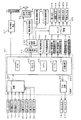
図2は、主基板(遊技制御基板)31における回路構成の一例を示すブロック図である。なお、図2は、払出制御基板37および演出制御基板80等も示されている。主基板31には、プログラムに従ってパチンコ遊技機1を制御する遊技制御用マイクロコンピュータ(遊技制御手段に相当)560が搭載されている。遊技制御用マイクロコンピュータ560は、ゲーム制御(遊技進行制御)用のプログラム等を記憶するROM54、ワークメモリとして使用される記憶手段としてのRAM55、プログラムに従って制御動作を行うCPU56およびI/Oポート部57を含む。この実施の形態では、ROM54およびRAM55は遊技制御用マイクロコンピュータ560に内蔵されている。すなわち、遊技制御用マイクロコンピュータ560は、1チップマイクロコンピュータである。1チップマイクロコンピュータには、少なくともCPU56のほかRAM55が内蔵されていればよく、ROM54は外付けであっても内蔵されていてもよい。また、I/Oポート部57は、外付けであってもよい。遊技制御用マイクロコンピュータ560には、さらに、ハードウェア乱数(ハードウェア回路が発生する乱数)を発生する乱数回路503が内蔵されている。
FIG. 2 is a block diagram showing an example of the circuit configuration of the main board (game control board) 31. FIG. 2 also shows a
また、RAM55は、その一部または全部が電源基板910において作成されるバックアップ電源によってバックアップされている不揮発性記憶手段としてのバックアップRAMである。すなわち、遊技機に対する電力供給が停止しても、所定期間(バックアップ電源としてのコンデンサが放電してバックアップ電源が電力供給不能になるまで)は、RAM55の一部または全部の内容は保存される。特に、少なくとも、遊技状態すなわち遊技制御手段の制御状態に応じたデータ(特別図柄プロセスフラグなど)と未払出賞球数を示すデータは、バックアップRAMに保存される。遊技制御手段の制御状態に応じたデータとは、停電等が生じた後に復旧した場合に、そのデータにもとづいて、制御状態を停電等の発生前に復旧させるために必要なデータである。また、制御状態に応じたデータと未払出賞球数を示すデータとを遊技の進行状態を示すデータと定義する。なお、この実施の形態では、RAM55の全部が、電源バックアップされているとする。 The RAM 55 is a backup RAM as a non-volatile storage means, part or all of which is backed up by a backup power source created on the power supply substrate 910. That is, even if the power supply to the gaming machine is stopped, a part or all of the contents of the RAM 55 is stored for a predetermined period (until the capacitor as the backup power supply is discharged and the backup power supply cannot be supplied). In particular, at least data (a special symbol process flag or the like) corresponding to the game state, that is, the control state of the game control means, and data indicating the number of unpaid winning balls are stored in the backup RAM. The data corresponding to the control state of the game control means is data necessary for restoring the control state before the occurrence of a power failure or the like based on the data when the power is restored after a power failure or the like occurs. Further, data corresponding to the control state and data indicating the number of unpaid prize balls are defined as data indicating the progress state of the game. In this embodiment, it is assumed that the entire RAM 55 is backed up.
なお、遊技制御用マイクロコンピュータ560においてCPU56がROM54に格納されているプログラムに従って制御を実行するので、以下、遊技制御用マイクロコンピュータ560(またはCPU56)が実行する(または、処理を行う)ということは、具体的には、CPU56がプログラムに従って制御を実行することである。このことは、主基板31以外の他の基板に搭載されているマイクロコンピュータについても同様である。
In the
乱数回路503は、特別図柄の可変表示の表示結果により大当りとするか否か判定するための判定用の乱数を発生するために用いられるハードウェア回路である。乱数回路503は、初期値(例えば、0)と上限値(例えば、65535)とが設定された数値範囲内で、数値データを、設定された更新規則に従って更新し、ランダムなタイミングで発生する始動入賞時が数値データの読出(抽出)時であることにもとづいて、読出される数値データが乱数値となる乱数発生機能を有する。
The
乱数回路503は、数値データの更新範囲の選択設定機能(初期値の選択設定機能、および、上限値の選択設定機能)、数値データの更新規則の選択設定機能、および数値データの更新規則の選択切換え機能等の各種の機能を有する。このような機能によって、生成する乱数のランダム性を向上させることができる。
The
また、遊技制御用マイクロコンピュータ560は、乱数回路503が更新する数値データの初期値を設定する機能を有している。例えば、ROM54等の所定の記憶領域に記憶された遊技制御用マイクロコンピュータ560のIDナンバ(遊技制御用マイクロコンピュータ560の各製品ごとに異なる数値で付与されたIDナンバ)を用いて所定の演算を行なって得られた数値データを、乱数回路503が更新する数値データの初期値として設定する。そのような処理を行うことによって、乱数回路503が発生する乱数のランダム性をより向上させることができる。
Further, the
また、ゲートスイッチ32a、始動口スイッチ13a、カウントスイッチ23、入賞口スイッチ29a,30a,33a,39aからの検出信号を遊技制御用マイクロコンピュータ560に与える入力ドライバ回路58も主基板31に搭載されている。また、可変入賞球装置15を開閉するソレノイド16、および大入賞口を形成する特別可変入賞球装置20を開閉するソレノイド21を遊技制御用マイクロコンピュータ560からの指令に従って駆動する出力回路59も主基板31に搭載されている。
Further, an
また、遊技制御用マイクロコンピュータ560は、特別図柄を可変表示する第1特別図柄表示器8a、第2特別図柄表示器8b、普通図柄を可変表示する普通図柄表示器10、第1特別図柄保留記憶表示器18a、第2特別図柄保留記憶表示器18bおよび普通図柄保留記憶表示器41の表示制御を行う。
In addition, the
なお、大当り遊技状態の発生を示す大当り情報等の情報出力信号をホールコンピュータ等の外部装置に対して出力する情報出力回路(図示せず)も主基板31に搭載されている。
An information output circuit (not shown) for outputting an information output signal such as jackpot information indicating the occurrence of a jackpot gaming state to an external device such as a hall computer is also mounted on the
この実施の形態では、演出制御基板80に搭載されている演出制御手段(演出制御用マイクロコンピュータで構成される。)が、中継基板77を介して遊技制御用マイクロコンピュータ560から演出内容を指示する演出制御コマンドを受信し、飾り図柄を可変表示する第1飾り図柄表示器9aおよび第2飾り図柄表示器9bと、演出図柄を可変表示する演出表示装置9との表示制御を行う。
In this embodiment, the effect control means (configured by the effect control microcomputer) mounted on the
また、演出制御基板80に搭載されている演出制御手段が、ランプドライバ基板35を介して、遊技盤に設けられている装飾LED25、および枠側に設けられている枠LED28の表示制御を行うとともに、音声出力基板70を介してスピーカ27からの音出力の制御を行う。
The effect control means mounted on the
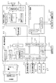
図3は、中継基板77、演出制御基板80、ランプドライバ基板35および音声出力基板70の回路構成例を示すブロック図である。なお、図3に示す例では、ランプドライバ基板35および音声出力基板70には、マイクロコンピュータは搭載されていないが、マイクロコンピュータを搭載してもよい。また、ランプドライバ基板35および音声出力基板70を設けずに、演出制御に関して演出制御基板80のみを設けてもよい。
FIG. 3 is a block diagram illustrating a circuit configuration example of the
演出制御基板80は、演出制御用CPU101、および演出図柄プロセスフラグ等の演出に関する情報を記憶するRAMを含む演出制御用マイクロコンピュータ100を搭載している。なお、RAMは外付けであってもよい。この実施の形態では、演出制御用マイクロコンピュータ100におけるRAMは電源バックアップされていない。演出制御基板80において、演出制御用CPU101は、内蔵または外付けのROM(図示せず)に格納されたプログラムに従って動作し、中継基板77を介して入力される主基板31からの取込信号(演出制御INT信号)に応じて、入力ドライバ102および入力ポート103を介して演出制御コマンドを受信する。また、演出制御用CPU101は、演出制御コマンドにもとづいて、VDP(ビデオディスプレイプロセッサ)109に演出表示装置9の表示制御を行わせる。
The
この実施の形態では、演出制御用マイクロコンピュータ100と共動して演出表示装置9の表示制御を行うVDP109が演出制御基板80に搭載されている。VDP109は、演出制御用マイクロコンピュータ100とは独立したアドレス空間を有し、そこにVRAMをマッピングする。VRAMは、画像データを展開するためのバッファメモリである。そして、VDP109は、VRAM内の画像データをフレームメモリを介して演出表示装置9に出力する。
In this embodiment, a
演出制御用CPU101は、受信した演出制御コマンドに従ってCGROM(図示せず)から必要なデータを読み出すための指令をVDP109に出力する。CGROMは、演出表示装置9に表示されるキャラクタ画像データや動画像データ、具体的には、人物、文字、図形や記号等(演出図柄を含む)、および背景画像のデータをあらかじめ格納しておくためのROMである。VDP109は、演出制御用CPU101の指令に応じて、CGROMから画像データを読み出す。そして、VDP109は、読み出した画像データにもとづいて表示制御を実行する。
The
演出制御コマンドおよび演出制御INT信号は、演出制御基板80において、まず、入力ドライバ102に入力する。入力ドライバ102は、中継基板77から入力された信号を演出制御基板80の内部に向かう方向にしか通過させない(演出制御基板80の内部から中継基板77への方向には信号を通過させない)信号方向規制手段としての単方向性回路でもある。
The effect control command and the effect control INT signal are first input to the
中継基板77には、主基板31から入力された信号を演出制御基板80に向かう方向にしか通過させない(演出制御基板80から中継基板77への方向には信号を通過させない)信号方向規制手段としての単方向性回路74が搭載されている。単方向性回路として、例えばダイオードやトランジスタが使用される。図3には、ダイオードが例示されている。また、単方向性回路は、各信号毎に設けられる。さらに、単方向性回路である出力ポート571を介して主基板31から演出制御コマンドおよび演出制御INT信号が出力されるので、中継基板77から主基板31の内部に向かう信号が規制される。すなわち、中継基板77からの信号は主基板31の内部(遊技制御用マイクロコンピュータ560側)に入り込まない。なお、出力ポート571は、図2に示されたI/Oポート部57の一部である。また、出力ポート571の外側(中継基板77側)に、さらに、単方向性回路である信号ドライバ回路が設けられていてもよい。
As a signal direction regulating means, the signal inputted from the
また、演出制御用CPU101は、出力ポート106を介して、可動部材78を動作させるためにモータ86を駆動する。また、演出制御用CPU101は、出力ポート106を介して、演出羽根役物79a,79bを動作させるためのモータ87を駆動する。
The
また、演出制御用CPU101は、入力ポート107を介して、遊技者による操作ボタン120の押圧操作に応じて操作ボタン120からの信号を入力する。
In addition, the
さらに、演出制御用CPU101は、出力ポート105を介してランプドライバ基板35に対してLEDを駆動する信号を出力する。また、演出制御用CPU101は、出力ポート104を介して音声出力基板70に対して音番号データを出力する。
Further, the
ランプドライバ基板35において、LEDを駆動する信号は、入力ドライバ351を介してLEDドライバ352に入力される。LEDドライバ352は、LEDを駆動する信号にもとづいて枠LED28などの枠側に設けられている発光体に電流を供給する。また、遊技盤側に設けられている装飾LED25に電流を供給する。
In the
音声出力基板70において、音番号データは、入力ドライバ702を介して音声合成用IC703に入力される。音声合成用IC703は、音番号データに応じた音声や効果音を発生し増幅回路705に出力する。増幅回路705は、音声合成用IC703の出力レベルを、ボリューム706で設定されている音量に応じたレベルに増幅した音声信号をスピーカ27に出力する。音声データROM704には、音番号データに応じた制御データが格納されている。音番号データに応じた制御データは、所定期間(例えば演出図柄の変動期間)における効果音または音声の出力態様を時系列的に示すデータの集まりである。
In the
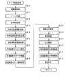
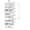
次に、遊技機の動作について説明する。図4は、主基板31における遊技制御用マイクロコンピュータ560が実行するメイン処理を示すフローチャートである。遊技機に対して電源が投入され電力供給が開始されると、リセット信号が入力されるリセット端子の入力レベルがハイレベルになり、遊技制御用マイクロコンピュータ560(具体的には、CPU56)は、プログラムの内容が正当か否か確認するための処理であるセキュリティチェック処理を実行した後、ステップS1以降のメイン処理を開始する。メイン処理において、CPU56は、まず、必要な初期設定を行う。
Next, the operation of the gaming machine will be described. FIG. 4 is a flowchart showing a main process executed by the
初期設定処理において、CPU56は、まず、割込禁止に設定する(ステップS1)。次に、割込モードを割込モード2に設定し(ステップS2)、スタックポインタにスタックポインタ指定アドレスを設定する(ステップS3)。そして、内蔵デバイスの初期化(内蔵デバイス(内蔵周辺回路)であるCTC(カウンタ/タイマ)およびPIO(パラレル入出力ポート)の初期化など)を行った後(ステップS4)、RAM55をアクセス可能状態に設定する(ステップS5)。なお、割込モード2は、CPU56が内蔵する特定レジスタ(Iレジスタ)の値(1バイト)と内蔵デバイスが出力する割込ベクタ(1バイト:最下位ビット0)とから合成されるアドレスが、割込番地を示すモードである。
In the initial setting process, the CPU 56 first sets the interrupt prohibition (step S1). Next, the interrupt mode is set to interrupt mode 2 (step S2), and a stack pointer designation address is set to the stack pointer (step S3). Then, after initialization of the built-in device (initialization of CTC (counter / timer) and PIO (parallel input / output port) which are built-in devices (built-in peripheral circuits)) (step S4), the RAM 55 is accessible. (Step S5). In the interrupt
次いで、CPU56は、入力ポートを介して入力されるクリアスイッチ(例えば、電源基板に搭載されている。)の出力信号の状態を確認する(ステップS6)。その確認においてオンを検出した場合には、CPU56は、通常の初期化処理を実行する(ステップS10〜S15)。 Next, the CPU 56 checks the state of the output signal of the clear switch (for example, mounted on the power supply board) input via the input port (step S6). When the ON is detected in the confirmation, the CPU 56 executes normal initialization processing (steps S10 to S15).
クリアスイッチがオンの状態でない場合には、遊技機への電力供給が停止したときにバックアップRAM領域のデータ保護処理(例えばパリティデータの付加等の電力供給停止時処理)が行われたか否か確認する(ステップS7)。そのような保護処理が行われていないことを確認したら、CPU56は初期化処理を実行する。バックアップRAM領域にバックアップデータがあるか否かは、例えば、電力供給停止時処理においてバックアップRAM領域に設定されるバックアップフラグの状態によって確認される。 If the clear switch is not on, check whether data protection processing of the backup RAM area (for example, power supply stop processing such as addition of parity data) was performed when power supply to the gaming machine was stopped (Step S7). When it is confirmed that such protection processing is not performed, the CPU 56 executes initialization processing. Whether there is backup data in the backup RAM area is confirmed, for example, by the state of the backup flag set in the backup RAM area in the power supply stop process.
電力供給停止時処理が行われたことを確認したら、CPU56は、バックアップRAM領域のデータチェックを行う(ステップS8)。この実施の形態では、データチェックとしてパリティチェックを行う。よって、ステップS8では、算出したチェックサムと、電力供給停止時処理で同一の処理によって算出され保存されているチェックサムとを比較する。不測の停電等の電力供給停止が生じた後に復旧した場合には、バックアップRAM領域のデータは保存されているはずであるから、チェック結果(比較結果)は正常(一致)になる。チェック結果が正常でないということは、バックアップRAM領域のデータが、電力供給停止時のデータとは異なっていることを意味する。そのような場合には、内部状態を電力供給停止時の状態に戻すことができないので、電力供給の停止からの復旧時でない電源投入時に実行される初期化処理を実行する。 When it is confirmed that the power supply stop process has been performed, the CPU 56 performs data check of the backup RAM area (step S8). In this embodiment, a parity check is performed as a data check. Therefore, in step S8, the calculated checksum is compared with the checksum calculated and stored by the same process in the power supply stop process. When the power supply is stopped after an unexpected power failure or the like, the data in the backup RAM area should be saved, so the check result (comparison result) is normal (matched). That the check result is not normal means that the data in the backup RAM area is different from the data when the power supply is stopped. In such a case, since the internal state cannot be returned to the state when the power supply is stopped, an initialization process that is executed when the power is turned on is not performed when the power supply is stopped.
チェック結果が正常であれば、CPU56は、遊技制御手段の内部状態と演出制御手段等の電気部品制御手段の制御状態を電力供給停止時の状態に戻すための遊技状態復旧処理(ステップS41〜S43の処理)を行う。具体的には、ROM54に格納されているバックアップ時設定テーブルの先頭アドレスをポインタに設定し(ステップS41)、バックアップ時設定テーブルの内容を順次作業領域(RAM55内の領域)に設定する(ステップS42)。作業領域はバックアップ電源によって電源バックアップされている。バックアップ時設定テーブルには、作業領域のうち初期化してもよい領域についての初期化データが設定されている。ステップS41およびS42の処理によって、作業領域のうち初期化してはならない部分については、保存されていた内容がそのまま残る。初期化してはならない部分とは、例えば、電力供給停止前の遊技状態を示すデータ(特別図柄プロセスフラグ、確変フラグ、時短フラグなど)、出力ポートの出力状態が保存されている領域(出力ポートバッファ)、未払出賞球数を示すデータが設定されている部分などである。
If the check result is normal, the CPU 56 recovers the game state restoration process (steps S41 to S43) for returning the internal state of the game control means and the control state of the electrical component control means such as the effect control means to the state when the power supply is stopped. Process). Specifically, the start address of the backup setting table stored in the
また、CPU56は、電力供給復旧時の初期化コマンドとしての停電復旧指定コマンド(停電復旧1指定コマンド)を演出制御基板80に送信する(ステップS43)。そして、ステップS14に移行する。
Further, the CPU 56 transmits a power failure restoration designation command (
なお、この実施の形態では、バックアップフラグとチェックデータとの双方を用いてバックアップRAM領域のデータが保存されているか否か確認しているが、いずれか一方のみを用いてもよい。すなわち、バックアップフラグとチェックデータとのいずれかを、遊技状態復旧処理を実行するための契機としてもよい。 In this embodiment, it is confirmed whether the data in the backup RAM area is stored using both the backup flag and the check data. However, only one of them may be used. That is, either the backup flag or the check data may be used as an opportunity for executing the game state restoration process.
初期化処理では、CPU56は、まず、RAMクリア処理を行う(ステップS10)。なお、RAMクリア処理によって、所定のデータ(例えば大当り判定用乱数を生成するためのカウンタのカウント値のデータ)は0に初期化されるが、任意の値またはあらかじめ決められている値に初期化するようにしてもよい。また、RAM55の全領域を初期化せず、所定のデータ(例えば大当り判定用乱数を生成するためのカウンタのカウント値のデータ)をそのままにしてもよい。また、ROM54に格納されている初期化時設定テーブルの先頭アドレスをポインタに設定し(ステップS11)、初期化時設定テーブルの内容を順次RAM55における作業領域に設定する(ステップS12)。
In the initialization process, the CPU 56 first performs a RAM clear process (step S10). The RAM clear process initializes predetermined data (for example, count value data of a counter for generating a big hit determination random number) to 0, but is initialized to an arbitrary value or a predetermined value. You may make it do. Alternatively, the entire area of the RAM 55 may not be initialized, and predetermined data (for example, count value data of a counter for generating a big hit determination random number) may be left as it is. Further, the initial address of the initialization setting table stored in the
ステップS11およびS12の処理によって、特別図柄プロセスフラグなど制御状態に応じて選択的に処理を行うためのフラグに初期値が設定される。 By the processing in steps S11 and S12, an initial value is set to a flag for selectively performing processing according to the control state, such as a special symbol process flag.
また、CPU56は、サブ基板(主基板31以外のマイクロコンピュータが搭載された基板。)を初期化するための初期化指定コマンド(遊技制御用マイクロコンピュータ560が初期化処理を実行したことを示すコマンドでもある。)を演出制御基板80に送信する(ステップS13)。例えば、演出制御基板80に搭載されている演出制御用マイクロコンピュータ100は、初期化指定コマンドを受信すると、演出表示装置9において、遊技機の制御の初期化がなされたことを報知するための画面表示、すなわち初期化報知を行う。なお、初期化処理において、CPU56は、客待ちデモンストレーション指定(デモ指定)コマンドも送信する。
In addition, the CPU 56 initializes a sub board (a board on which a microcomputer other than the
また、CPU56は、乱数回路503を初期設定する乱数回路設定処理を実行する(ステップS14)。CPU56は、例えば、乱数回路設定プログラムに従って処理を実行することによって、乱数回路503にランダムRの値を更新させるための設定を行う。
Further, the CPU 56 executes a random number circuit setting process for initial setting of the random number circuit 503 (step S14). For example, the CPU 56 performs setting according to the random number circuit setting program to cause the
そして、CPU56は、所定時間(例えば2ms)毎に定期的にタイマ割込がかかるように遊技制御用マイクロコンピュータ560に内蔵されているCTCのレジスタの設定を行なう(ステップS15)。すなわち、初期値として例えば2msに相当する値が所定のレジスタ(時間定数レジスタ)に設定される。この実施の形態では、2ms毎に定期的にタイマ割込がかかるとする。
Then, the CPU 56 sets a CTC register built in the
初期化処理の実行(ステップS10〜S15)が完了すると、CPU56は、メイン処理で、表示用乱数更新処理(ステップS17)および初期値用乱数更新処理(ステップS18)を繰り返し実行する。表示用乱数更新処理および初期値用乱数更新処理を実行するときには割込禁止状態に設定し(ステップS16)、表示用乱数更新処理および初期値用乱数更新処理の実行が終了すると割込許可状態に設定する(ステップS19)。この実施の形態では、表示用乱数とは、変動パターン等を決定するための乱数であり、表示用乱数更新処理とは、表示用乱数を発生するためのカウンタのカウント値を更新する処理である。また、初期値用乱数更新処理とは、初期値用乱数を発生するためのカウンタのカウント値を更新する処理である。この実施の形態では、初期値用乱数とは、普通図柄の当りとするか否か決定するための乱数を発生するためのカウンタ(普通図柄当り判定用乱数発生カウンタ)等のカウント値の初期値を決定するための乱数である。後述する遊技の進行を制御する遊技制御処理(遊技制御用マイクロコンピュータ560が、遊技機に設けられている可変表示装置、可変入賞球装置、球払出装置等の遊技用の装置を、自身で制御する処理、または他のマイクロコンピュータに制御させるために指令信号を送信する処理、遊技装置制御処理ともいう)において、大当り判定用乱数発生カウンタ等のカウント値が1周(乱数の取りうる値の最小値から最大値までの間の数値の個数分歩進したこと)すると、そのカウンタに初期値が設定される。
When the execution of the initialization process (steps S10 to S15) is completed, the CPU 56 repeatedly executes the display random number update process (step S17) and the initial value random number update process (step S18) in the main process. When executing the display random number update process and the initial value random number update process, the interrupt disabled state is set (step S16). When the display random number update process and the initial value random number update process are finished, the interrupt enabled state is set. Set (step S19). In this embodiment, the display random number is a random number for determining a variation pattern or the like, and the display random number update process is a process for updating the count value of the counter for generating the display random number. . The initial value random number update process is a process for updating the count value of the counter for generating the initial value random number. In this embodiment, the initial value random number is an initial value of a count value such as a counter for generating a random number for determining whether or not to hit a normal symbol (normal symbol determination random number generation counter). It is a random number for determining. A game control process for controlling the progress of the game, which will be described later (the
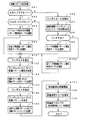
タイマ割込が発生すると、CPU56は、図5に示すステップS20〜S34のタイマ割込処理を実行する。タイマ割込処理において、まず、電源断信号が出力されたか否か(オン状態になったか否か)を検出する電源断検出処理を実行する(ステップS20)。電源断信号は、例えば電源基板に搭載されている電源監視回路920が、遊技機に供給される電源の電圧の低下を検出した場合に出力する。そして、電源断検出処理において、CPU56は、電源断信号が出力されたことを検出したら、必要なデータをバックアップRAM領域に保存するための電力供給停止時処理を実行する。次いで、入力ドライバ回路58を介して、ゲートスイッチ32a、第1始動口スイッチ13a、第2始動口スイッチ14a、カウントスイッチ23、および入賞口スイッチ29a,30a,33a,39aの検出信号を入力し、それらの状態判定を行う(スイッチ処理:ステップS21)。
When the timer interrupt occurs, the CPU 56 executes the timer interrupt process of steps S20 to S34 shown in FIG. In the timer interrupt process, first, a power-off detection process for detecting whether or not a power-off signal is output (whether or not an on-state is turned on) is executed (step S20). The power-off signal is output, for example, when the power monitoring circuit 920 mounted on the power board detects a decrease in the voltage of the power supplied to the gaming machine. In the power-off detection process, when detecting that the power-off signal has been output, the CPU 56 executes a power supply stop process for storing necessary data in the backup RAM area. Next, detection signals of the
次に、CPU56は、第1特別図柄表示器8a、第2特別図柄表示器8b、普通図柄表示器10、第1特別図柄保留記憶表示器18a、第2特別図柄保留記憶表示器18b、普通図柄保留記憶表示器41の表示制御を行う表示制御処理を実行する(ステップS22)。第1特別図柄表示器8a、第2特別図柄表示器8bおよび普通図柄表示器10については、ステップS32,S33で設定される出力バッファの内容に応じて各表示器に対して駆動信号を出力する制御を実行する。
Next, the CPU 56 includes a first
また、遊技制御に用いられる普通当り図柄決定用の乱数等の各判定用乱数を生成するための各カウンタのカウント値を更新する処理を行う(判定用乱数更新処理:ステップS23)。CPU56は、さらに、初期値用乱数および表示用乱数を生成するためのカウンタのカウント値を更新する処理を行う(初期値用乱数更新処理,表示用乱数更新処理:ステップS24,S25)。 In addition, a process of updating the count value of each counter for generating each random number for determination such as a random number for determining a normal winning symbol used for game control is performed (determination random number update process: step S23). The CPU 56 further performs a process of updating the count value of the counter for generating the initial value random number and the display random number (initial value random number update process, display random number update process: steps S24 and S25).
さらに、CPU56は、特別図柄プロセス処理を行う(ステップS26)。特別図柄プロセス処理では、第1特別図柄表示器8a、第2特別図柄表示器8bおよび大入賞口を所定の順序で制御するための特別図柄プロセスフラグに従って該当する処理を実行する。CPU56は、特別図柄プロセスフラグの値を、遊技状態に応じて更新する。
Further, the CPU 56 performs special symbol process processing (step S26). In the special symbol process, corresponding processing is executed according to a special symbol process flag for controlling the first
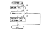
次いで、普通図柄プロセス処理を行う(ステップS27)。普通図柄プロセス処理では、CPU56は、普通図柄表示器10の表示状態を所定の順序で制御するための普通図柄プロセスフラグに従って該当する処理を実行する。CPU56は、普通図柄プロセスフラグの値を、遊技状態に応じて更新する。
Next, normal symbol process processing is performed (step S27). In the normal symbol process, the CPU 56 executes a corresponding process according to the normal symbol process flag for controlling the display state of the
また、CPU56は、演出制御用マイクロコンピュータ100に演出制御コマンドを送出する処理を行う(演出制御コマンド制御処理:ステップS28)。 Further, the CPU 56 performs a process of sending an effect control command to the effect control microcomputer 100 (effect control command control process: step S28).
さらに、CPU56は、例えばホール管理用コンピュータに供給される大当り情報、始動情報、確率変動情報などのデータを出力する情報出力処理を行う(ステップS29)。 Further, the CPU 56 performs information output processing for outputting data such as jackpot information, start information, probability variation information supplied to the hall management computer, for example (step S29).
また、CPU56は、第1始動口スイッチ13a、第2始動口スイッチ14a、カウントスイッチ23および入賞口スイッチ29a,30a,33a,39aの検出信号にもとづく賞球個数の設定などを行う賞球処理を実行する(ステップS30)。具体的には、第1始動口スイッチ13a、第2始動口スイッチ14a、カウントスイッチ23および入賞口スイッチ29a,30a,33a,39aのいずれかがオンしたことにもとづく入賞検出に応じて、払出制御基板37に搭載されている払出制御用マイクロコンピュータに賞球個数を示す払出制御コマンド(賞球個数信号)を出力する。払出制御用マイクロコンピュータは、賞球個数を示す払出制御コマンドに応じて球払出装置97を駆動する。
Further, the CPU 56 performs prize ball processing for setting the number of prize balls based on detection signals from the first
この実施の形態では、出力ポートの出力状態に対応したRAM領域(出力ポートバッファ)が設けられているのであるが、CPU56は、出力ポートの出力状態に対応したRAM領域におけるソレノイドのオン/オフに関する内容を出力ポートに出力する(ステップS31:出力処理)。 In this embodiment, a RAM area (output port buffer) corresponding to the output state of the output port is provided. However, the CPU 56 relates to ON / OFF of the solenoid in the RAM area corresponding to the output state of the output port. The contents are output to the output port (step S31: output process).
また、CPU56は、特別図柄プロセスフラグの値に応じて特別図柄の演出表示を行うための特別図柄表示制御データを特別図柄表示制御データ設定用の出力バッファに設定する特別図柄表示制御処理を行う(ステップS32)。CPU56は、例えば、特別図柄プロセス処理でセットされる開始フラグがセットされると終了フラグがセットされるまで、変動速度が1コマ/0.2秒であれば、0.2秒が経過する毎に、出力バッファに設定される表示制御データの値を+1する。また、CPU56は、出力バッファに設定された表示制御データに応じて、ステップS22において駆動信号を出力することによって、第1特別図柄表示器8aおよび第2特別図柄表示器8bにおける第1特別図柄および第2特別図柄の可変表示を実行する。
Further, the CPU 56 performs special symbol display control processing for setting special symbol display control data for effect display of special symbols in the output buffer for setting the special symbol display control data according to the value of the special symbol process flag ( Step S32). For example, if the variation speed is 1 frame / 0.2 seconds until the end flag is set when the start flag set in the special symbol process is set, the CPU 56, for example, every 0.2 seconds passes. Then, the value of the display control data set in the output buffer is incremented by one. Further, the CPU 56 outputs a drive signal in step S22 in accordance with the display control data set in the output buffer, whereby the first special symbol on the first
さらに、CPU56は、普通図柄プロセスフラグの値に応じて普通図柄の演出表示を行うための普通図柄表示制御データを普通図柄表示制御データ設定用の出力バッファに設定する普通図柄表示制御処理を行う(ステップS33)。CPU56は、例えば、普通図柄の変動に関する開始フラグがセットされると終了フラグがセットされるまで、普通図柄の変動速度が0.2秒ごとに表示状態(「○」および「×」)を切り替えるような速度であれば、0.2秒が経過する毎に、出力バッファに設定される表示制御データの値(例えば、「○」を示す1と「×」を示す0)を切り替える。また、CPU56は、出力バッファに設定された表示制御データに応じて、ステップS22において駆動信号を出力することによって、普通図柄表示器10における普通図柄の演出表示を実行する。
Further, the CPU 56 performs a normal symbol display control process for setting normal symbol display control data for effect display of the normal symbol in the output buffer for setting the normal symbol display control data according to the value of the normal symbol process flag ( Step S33). For example, when the start flag for normal symbol fluctuation is set, the CPU 56 switches the display state (“◯” and “×”) for the normal symbol fluctuation speed every 0.2 seconds until the end flag is set. With such a speed, the value of the display control data set in the output buffer (for example, 1 indicating “◯” and 0 indicating “x”) is switched every 0.2 seconds. In addition, the CPU 56 executes a normal symbol effect display on the
その後、割込許可状態に設定し(ステップS34)、処理を終了する。 Thereafter, the interrupt permission state is set (step S34), and the process is terminated.
以上の制御によって、この実施の形態では、遊技制御処理は2ms毎に起動されることになる。なお、遊技制御処理は、タイマ割込処理におけるステップS21〜S33(ステップS29を除く。)の処理に相当する。また、この実施の形態では、タイマ割込処理で遊技制御処理が実行されているが、タイマ割込処理では例えば割込が発生したことを示すフラグのセットのみがなされ、遊技制御処理はメイン処理において実行されるようにしてもよい。 With the above control, in this embodiment, the game control process is started every 2 ms. The game control process corresponds to the processes of steps S21 to S33 (excluding step S29) in the timer interrupt process. In this embodiment, the game control process is executed by the timer interrupt process. However, in the timer interrupt process, for example, only a flag indicating that an interrupt has occurred is set, and the game control process is performed by the main process. May be executed.
第1特別図柄表示器8aまたは第2特別図柄表示器8bおよび演出表示装置9にはずれ図柄が停止表示される場合には、演出図柄の可変表示が開始されてから、演出図柄の可変表示状態がリーチ状態にならずに、リーチにならない所定の演出図柄の組み合わせが停止表示されることがある。このような演出図柄の可変表示態様を、可変表示結果がはずれ図柄になる場合における「非リーチ」(「通常はずれ」ともいう)の可変表示態様という。
When the shifted symbol is stopped and displayed on the first
第1特別図柄表示器8aまたは第2特別図柄表示器8bおよび演出表示装置9にはずれ図柄が停止表示される場合には、演出図柄の可変表示が開始されてから、演出図柄の可変表示状態がリーチ状態となったことに応じて、リーチ演出が実行された後に、または、リーチ演出が実行されずに、リーチにならない所定の演出図柄の組み合わせが停止表示されることがある。このような演出図柄の可変表示結果を、可変表示結果が「はずれ」となる場合における「リーチ」(「リーチはずれ」ともいう)の可変表示態様という。
When the shifted symbol is stopped and displayed on the first
この実施の形態では、第1特別図柄表示器8aまたは第2特別図柄表示器8bに大当り図柄が停止表示される場合には、演出図柄の可変表示状態がリーチ状態になった後にリーチ演出が実行され、またはリーチ演出が実行されずに、演出表示装置9における「左」、「中」、「右」の各図柄表示エリア9L、9C、9Rに、演出図柄が揃って停止表示される。
In this embodiment, when the big win symbol is stopped and displayed on the first
第1特別図柄表示器8aまたは第2特別図柄表示器8bに突然時短大当り図柄である「5」が停止表示される場合には、演出表示装置9において、演出図柄の可変表示態様が「突然確変大当り」である場合と同様に演出図柄の可変表示が行われた後、所定の突然時短大当り図柄(突然確変大当り図柄と同じ図柄。例えば「135」)が停止表示されることがある。第1特別図柄表示器8aまたは第2特別図柄表示器8bに突然時短大当り図柄である「5」が停止表示されることに対応する演出表示装置9における表示演出を「突然時短大当り」の可変表示態様という。
When “5”, which is a sudden and short-term hit symbol, is stopped and displayed suddenly on the first
ここで、突然時短大当りとは、大当りと比較して大入賞口の開放回数が少ない回数(この実施の形態では0.1秒間の開放を2回)まで許容される大当りであり、かつ、大当り遊技後の遊技状態を時短状態に移行させるような大当りである(すなわち、そのようにすることにより、遊技者に対して突然に時短状態になったかのうように見せるものである)。また、突然確変大当りとは、大当り遊技状態において大入賞口の開放回数が少ない回数(この実施の形態では0.1秒間の開放を2回)まで許容されるが大入賞口の開放時間が極めて短い大当りであり、かつ、大当り遊技後の遊技状態を確変状態に移行させるような大当りである(すなわち、そのようにすることにより、遊技者に対して突然に確変状態となったかのように見せるものである)。つまり、この実施の形態では、突然確変大当りと突然時短大当りとは、大入賞口の開放パターンが同じである。そのように制御することによって、大入賞口の0.1秒間の開放が2回行われると、突然確変大当りであるか突然時短大当りであるかまでは認識できないので、遊技者に対して高確率状態(確変状態)を期待させることができ、遊技の興趣を向上させることができる。 Here, the sudden short and big jackpot is a jackpot that is allowed up to the number of times that the number of times of opening of the big winning opening is smaller than that of the jackpot (in this embodiment, the opening for 0.1 second is twice), and the jackpot It is a big hit that shifts the gaming state after the game to the short-time state (that is, it makes it appear as if the player suddenly became short-time state by doing so). In addition, the sudden probability change big hit is allowed up to a small number of times of opening of the big winning opening in the big hit gaming state (in this embodiment, opening for 0.1 second is twice), but the opening time of the big winning opening is extremely large. It is a big jackpot that is a short jackpot and the game state after the big jackpot game is shifted to a probabilistic state (that is, by doing so, it appears to the player as if it suddenly became a probable state) Is). In other words, in this embodiment, the sudden winning change jackpot and the sudden time bonus jackpot have the same opening pattern of the big prize opening. By controlling in such a manner, if the winning opening is opened twice for 0.1 seconds, it is impossible to recognize whether it is a sudden probability change big hit or a sudden shortage big hit. A state (probable change state) can be expected, and the interest of the game can be improved.
図6は、可変表示結果がはずれ図柄になる場合における演出図柄の可変表示態様が「非リーチ」である場合と「リーチ」である場合のそれぞれに対応してあらかじめ用意された演出図柄の変動パターンを示す説明図である。図6に示すように、この実施の形態では、演出図柄の可変表示態様が「非リーチ」である場合に対応した変動パターンとして、非リーチPA1−1〜非リーチPA1−5の変動パターンが用意されている。また、演出図柄の可変表示態様が「リーチ」である場合に対応した変動パターンとして、ノーマルPA2−1〜ノーマルPA2−4、スーパーPA3−1〜スーパーPA3−6、スーパーPB3−1〜スーパーPB3−3、スーパーPC3−1〜スーパーPC3−2の変動パターンが用意されている。なお、図6に示すように、リーチしない場合に使用され擬似連の演出を伴う非リーチPA1−5の変動パターンについては、再変動が2回行われる。リーチする場合に使用され擬似連の演出を伴う変動パターンについては、再変動が3回行われる。 FIG. 6 shows the variation patterns of the effect symbols prepared in advance corresponding to the cases where the variable display mode of the effect symbol is “non-reach” and “reach” when the variable display result is an off-symbol. It is explanatory drawing which shows. As shown in FIG. 6, in this embodiment, non-reach PA1-1 to non-reach PA1-5 variation patterns are prepared as variation patterns corresponding to the case where the variable display mode of the effect symbol is “non-reach”. Has been. Further, as variation patterns corresponding to the case where the variable display mode of the effect symbol is “reach”, normal PA2-1 to normal PA2-4, super PA3-1 to super PA3-6, super PB3-1 to super PB3— 3. Fluctuation patterns of Super PC 3-1 to Super PC 3-2 are prepared. As shown in FIG. 6, the re-variation is performed twice for the non-reach PA 1-5 variation pattern that is used when the reach is not performed and has a pseudo-continuous effect. Re-variation is performed three times for the variation pattern that is used in the case of reaching and accompanied by the effect of the pseudo-ream.
図7および図8は、可変表示結果が大当り図柄になる場合に対応してあらかじめ用意された演出図柄の変動パターンを例示する説明図である。この実施の形態では、演出モードがバトルモードに移行されれている場合には、可変表示結果が大当り図柄となる場合における演出図柄の変動表示中に所定のバトル演出(味方と敵のキャラクタがバトルを行う態様の演出)が実行される場合がある。図7は、可変表示結果が大当り図柄になる場合のうち所定のバトル演出を伴わない場合にに対応してあらかじめ用意された演出図柄の変動パターンを例示している。また、図8は、可変表示結果が大当り図柄になる場合のうち所定のバトル演出を伴う場合にに対応してあらかじめ用意された演出図柄の変動パターンを例示している。 FIG. 7 and FIG. 8 are explanatory diagrams illustrating the variation pattern of the effect symbol prepared in advance corresponding to the case where the variable display result becomes the big hit symbol. In this embodiment, when the effect mode has been shifted to the battle mode, a predetermined battle effect (a friend and an enemy character are in battle) during the variable display of the effect symbol when the variable display result is a jackpot symbol. May be performed). FIG. 7 exemplifies a variation pattern of an effect symbol prepared in advance corresponding to a case where a predetermined battle effect is not accompanied when the variable display result becomes a big hit symbol. Moreover, FIG. 8 illustrates the variation pattern of the effect symbols prepared in advance corresponding to the case where a predetermined battle effect is accompanied among the cases where the variable display result becomes a jackpot symbol.
図7に示すように、この実施の形態では、特別図柄の可変表示結果が大当り図柄になる場合のうち所定のバトル演出を伴わない場合に対応した変動パターンとして、ノーマルPA2−5〜ノーマルPA2−8、スーパーPA4−1〜スーパーPA4−6、スーパーPB4−1〜スーパーPB4−3、スーパーPD1−1およびスーパーPD1−2、特殊PG1−1〜特殊PG1−3、特殊PG2−1〜特殊PG2−2の変動パターンが用意されている。なお、図7において、特殊PG1−1〜特殊PG1−3、特殊PG2−1〜特殊PG2−2の変動パターンは、突然確変大当りまたは突然時短大当りとなる場合に使用される変動パターンである。また、図7に示すように、突然確変大当りまたは突然時短大当りでない場合に使用され擬似連の演出を伴う変動パターンについては、再変動が3回行われる。突然確変大当りまたは突然時短大当りの場合に使用され擬似連の演出を伴う特殊PG1−3の変動パターンについては、再変動が2回行われる。 As shown in FIG. 7, in this embodiment, normal PA2-5 to normal PA2− are fluctuation patterns corresponding to a case where a predetermined battle effect is not accompanied, among the cases where the variable symbol display result of the special symbol is a big hit symbol. 8, Super PA4-1 to Super PA4-6, Super PB4-1 to Super PB4-3, Super PD1-1 and Super PD1-2, Special PG1-1 to Special PG1-3, Special PG2-1 to Special PG2- Two fluctuation patterns are prepared. In FIG. 7, the fluctuation patterns of special PG1-1 to special PG1-3 and special PG2-1 to special PG2-2 are fluctuation patterns used in the case of sudden probability variation big hit or sudden time shortage big hit. Further, as shown in FIG. 7, re-variation is performed three times for the variation pattern that is used when the sudden probability variation big hit or the sudden time short-lived big hit is not performed, and accompanied by the effect of the pseudo-ream. For the variation pattern of the special PG 1-3 that is used in the case of sudden probability variation big hit or sudden short time big hit and accompanied by the effect of pseudo-ream, re-variation is performed twice.
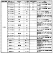
また、図8に示すように、この実施の形態では、特別図柄の可変表示結果が大当り図柄になる場合のうち所定のバトル演出を伴う場合に対応した変動パターンとして、バトルPA5−1〜バトルPA5−17の変動パターンが用意されている。 In addition, as shown in FIG. 8, in this embodiment, battle PA5-1 to battle PA5 are used as variation patterns corresponding to the case where a predetermined battle effect is accompanied in the case where the variable symbol display result of the special symbol is a big hit symbol. A variation pattern of -17 is prepared.
この実施の形態では、後述するように、大当り種別として、15R確変大当り、7R確変大当り、突然確変大当り、および突然時短大当りがある。このうち、15R確変大当りまたは7R確変大当りとなった場合には、大当り遊技終了後に演出モードがバトルモードに移行され、以降の演出図柄の変動表示において所定のバトル演出が実行される場合がある。バトルモードに移行されているときに再び15R確変大当りまたは7R確変大当りとなった場合には、演出図柄の変動表示中に味方のキャラクタがバトルに勝利する態様でバトル演出が実行され、その大当り遊技終了後もバトルモードが継続される。また、バトルモードに移行されているときに突然確変大当りとなった場合には、演出図柄の変動表示中にバトルの決着がつかない態様でバトル演出が実行され、その突然確変大当り遊技終了後のバトルモードが継続される。一方、バトルモードに移行されているときに突然時短大当りとなった場合には、演出図柄の変動表示中に味方のキャラクタがバトルに敗北する態様でバトル演出が実行され、バトルモードが終了される。 In this embodiment, as will be described later, the types of big hits include 15R probability variable big hit, 7R probability variable big hit, sudden probability variable big hit, and sudden short time big hit. Among these, when 15R probability variation big hit or 7R probability variation big hit is reached, the effect mode is shifted to the battle mode after the big hit game ends, and a predetermined battle effect may be executed in the subsequent variation display of the effect symbols. If the 15R probability change big hit or 7R probability change big hit is made again when the mode is shifted to the battle mode, the battle effect is executed in such a manner that the ally character wins the battle while the effect symbols change display, and the jackpot game The battle mode continues even after the end. Also, if the game is suddenly changed to the battle mode, the battle effect is executed in such a manner that the battle cannot be settled during the change display of the production symbol, and after the sudden probability change big hit game ends. Battle mode is continued. On the other hand, when the time is suddenly hit when the mode is shifted to the battle mode, the battle effect is executed in such a manner that the ally character loses the battle during the change display of the effect symbol, and the battle mode is ended. .
バトルPA5−1〜バトルPA5−2の変動パターンは、味方のキャラクタがバトルに敗北する態様のバトル演出を伴う変動パターンである。バトルPA5−1〜バトルPA5−2の変動パターンは、主として、突然時短大当りと決定されたときに選択される。なお、この実施の形態では、選択割合が低いものの、突然確変大当りと決定された場合であっても、バトルPA5−1〜バトルPA5−2の変動パターンが選択されることがある。 The variation pattern of battle PA5-1 to battle PA5-2 is a variation pattern accompanied by a battle effect in a mode in which the ally character is defeated by the battle. The variation pattern of the battle PA5-1 to the battle PA5-2 is mainly selected when it is determined that there is a sudden shortage hit. In this embodiment, although the selection ratio is low, the variation pattern of battle PA5-1 to battle PA5-2 may be selected even if it is suddenly determined to be a probable big hit.
バトルPA5−3〜バトルPA5−5の変動パターンは、味方のキャラクタがバトルに勝利する態様のバトル演出を伴う変動パターンである。このうち、バトルPA5−3〜バトルPA5−4の変動パターンは、15R確変大当りまたは7R確変大当りと決定されたときに選択される。また、バトルPA5−5の変動パターンは、15R確変大当りと決定されたときにのみ選択される。 The variation pattern of the battle PA5-3 to the battle PA5-5 is a variation pattern accompanied by a battle effect in such a manner that the ally character wins the battle. Among these, the variation pattern of battle PA5-3 to battle PA5-4 is selected when it is determined to be 15R probability variation big hit or 7R probability variation big hit. The variation pattern of battle PA5-5 is selected only when it is determined that the 15R probability variation big hit.
バトルPA5−6〜バトルPA5−15の変動パターンは、バトルの決着がつかない態様のバトル演出を伴う変動パターンである。バトルPA5−6〜バトルPA5−15の変動パターンは、突然確変大当りと決定されたときに選択される。 The variation pattern of battle PA5-6 to battle PA5-15 is a variation pattern with a battle effect in a mode in which a battle cannot be settled. The variation pattern of battle PA5-6 to battle PA5-15 is selected when it is suddenly determined that the probability change big hit.
バトルPA5−16〜バトルPA5−17の変動パターンは、味方のキャラクタがバトルに敗北するものの復活して立ち直る態様のバトル演出を伴う変動パターンである。バトルPA5−16〜バトルPA5−17の変動パターンは、15R確変大当りまたは7R確変大当りと決定されたときに選択される。 The variation pattern of battle PA5-16 to battle PA5-17 is a variation pattern accompanied by a battle effect in a mode in which an ally character is defeated by a battle but revives and recovers. The variation pattern of battle PA5-16 to battle PA5-17 is selected when it is determined that 15R probability variation jackpot or 7R probability variation jackpot.
図9は、各乱数を示す説明図である。各乱数は、以下のように使用される。
(2−1)ランダム2−1(MR2−1):大当りの種類(15R確変大当り、7R確変大当り、突然確変大当り、突然時短大当り)を決定する(大当り種別判定用)
(2−2)ランダム2−2(MR2−2): リーチとするか否か決定する(リーチ判定用)
(3)ランダム3(MR3):変動パターンの種類(種別)を決定する(変動パターン種別判定用)
(4)ランダム4(MR4):変動パターン(変動時間)を決定する(変動パターン判定用)
(5)ランダム5(MR5):普通図柄にもとづく当りを発生させるか否か決定する(普通図柄当り判定用)
(6)ランダム6(MR6):ランダム5の初期値を決定する(ランダム5初期値決定用)
FIG. 9 is an explanatory diagram showing each random number. Each random number is used as follows.
(2-1) Random 2-1 (MR2-1): Determines the type of jackpot (15R probability variation big hit, 7R probability variation big hit, sudden probability variation big hit, sudden shortage big hit) (for big hit type judgment)
(2-2) Random 2-2 (MR2-2): Determines whether or not to reach (for reach determination)
(3) Random 3 (MR3): The type (type) of the variation pattern is determined (for variation pattern type determination)
(4) Random 4 (MR4): A variation pattern (variation time) is determined (for variation pattern determination)
(5) Random 5 (MR5): Determines whether or not to generate a hit based on the normal symbol (for normal symbol hit determination)
(6) Random 6 (MR6): Determine the initial value of random 5 (for determining the initial value of random 5)
図5に示された遊技制御処理におけるステップS23では、遊技制御用マイクロコンピュータ560は、(2−1)の大当り種別判定用乱数、および(5)の普通図柄当り判定用乱数を生成するためのカウンタのカウントアップ(1加算)を行う。すなわち、それらが判定用乱数であり、それら以外の乱数が表示用乱数(ランダム2−2、ランダム3、ランダム4)または初期値用乱数(ランダム6)である。なお、遊技効果を高めるために、上記の乱数以外の乱数も用いてもよい。また、この実施の形態では、大当り判定用乱数として、遊技制御用マイクロコンピュータ560に内蔵されたハードウェア(遊技制御用マイクロコンピュータ560の外部のハードウェアでもよい。)が生成する乱数を用いる。
In step S23 in the game control process shown in FIG. 5, the
図10(A),(B)は、大当り判定テーブルを示す説明図である。大当り判定テーブルとは、ROM54に記憶されているデータの集まりであって、ランダムRと比較される大当り判定値が設定されているテーブルである。大当り判定テーブルには、通常状態(確変状態でない遊技状態)において用いられる通常時大当り判定テーブルと、確変状態において用いられる確変時大当り判定テーブルとがある。通常時大当り判定テーブルには、図10(A)の左欄に記載されている各数値が設定され、確変時大当り判定テーブルには、図10(A)の右欄に記載されている各数値が設定されている。図10(A)に記載されている数値が大当り判定値である。
FIGS. 10A and 10B are explanatory diagrams showing a jackpot determination table. The jackpot determination table is a collection of data stored in the
CPU56は、所定の時期に、乱数回路503のカウント値を抽出して抽出値を大当り判定用乱数(ランダムR)の値とするのであるが、大当り判定用乱数値が図10(A)に示すいずれかの大当り判定値に一致すると、特別図柄に関して大当り(15R確変大当り、7R確変大当り、突然確変大当り、突然時短大当り)にすることに決定する。なお、図10(A)に示す「確率」は、大当りになる確率(割合)を示す。また、大当りにするか否か決定するということは、大当り遊技状態に移行させるか否か決定するということであるが、第1特別図柄表示器8aまたは第2特別図柄表示器8bにおける停止図柄を大当り図柄にするか否か決定するということでもある。
The CPU 56 extracts the count value of the
図10(B),(C)は、ROM54に記憶されている大当り種別判定テーブル131を示す説明図である。このうち、図10(B)は、遊技球が第1始動入賞口13に入賞したことにもとづく保留記憶を用いて(すなわち、第1特別図柄の変動表示が行われるとき)大当り種別を決定する場合の大当り種別判定テーブル(第1特別図柄用)131aである。また、図10(C)は、遊技球が第2始動入賞口14に入賞したことにもとづく保留記憶を用いて(すなわち、第2特別図柄の変動表示が行われるとき)大当り種別を決定する場合の大当り種別判定テーブル(第2特別図柄用)131bである。
FIGS. 10B and 10C are explanatory diagrams showing the big hit type determination table 131 stored in the
大当り種別判定テーブル131は、可変表示結果を大当り図柄にする旨の判定がなされたときに、大当り種別判定用の乱数(ランダム2−1)にもとづいて、大当りの種別を「15R確変大当り」、「7R確変大当り」、「突然確変大当り」、「突然時短大当り」のうちのいずれかに決定するために参照されるテーブルである。なお、「15R確変大当り」とは、15ラウンドの大当り遊技状態に制御し、その大当り遊技状態の終了後に確変状態に移行させる大当りである。また、「7R確変大当り」とは、7ラウンドの大当り遊技状態に制御し、その大当り遊技状態の終了後に確変状態に移行させる大当りである。大当り種別判定テーブル131には、ランダム2−1の値と比較される数値であって、「15R確変大当り」、「7R確変大当り」、「突然確変大当り」、「突然時短大当り」のそれぞれに対応した判定値(大当り種別判定値)が設定されている。CPU56は、ランダム2−1の値が大当り種別判定値のいずれかに一致した場合に、大当りの種別を、一致した大当り種別判定値に対応する種別に決定する。 When it is determined that the variable display result is a jackpot symbol, the jackpot type determination table 131 sets the jackpot type to “15R probability variable big hit” based on the random number (random 2-1) for determining the jackpot type. This table is referred to in order to determine any one of “7R probability variation big hit”, “sudden probability variation big hit”, and “sudden time sudden big hit”. The “15R probability variation jackpot” is a jackpot that is controlled to a 15-round jackpot gaming state and shifts to the probability variation state after the jackpot gaming state ends. The “7R probability variation jackpot” is a jackpot that is controlled to a seven-round jackpot gaming state and shifts to the probability variation state after the jackpot gaming state ends. The big hit type judgment table 131 is a numerical value to be compared with the value of the random 2-1, corresponding to each of “15R probability variation big hit”, “7R probability variation big hit”, “sudden probability variation big hit”, and “sudden time short big hit”. Judgment value (big hit type judgment value) is set. When the random value 2-1 matches any of the jackpot type determination values, the CPU 56 determines the jackpot type as a type corresponding to the matched jackpot type determination value.
図11(A)〜(D)および図12(E)〜(H)は、大当り用変動パターン種別判定テーブル132A〜132Hを示す説明図である。大当り用変動パターン種別判定テーブル132A〜132Hは、可変表示結果を大当り図柄にする旨の判定がなされたときに、大当り種別の判定結果に応じて、変動パターン種別を、変動パターン種別判定用の乱数(ランダム3)にもとづいて複数種類のうちのいずれかに決定するために参照されるテーブルである。なお、大当り用変動パターン種別判定テーブル132A〜132Hのうち、図12(E)〜(H)に示す大当り用変動パターン種別判定テーブル132E〜132Hは、演出モードがバトルモードに移行されている場合に参照されるテーブルである。また、図12(A)〜(D)に示す大当り用変動パターン種別判定テーブル132A〜132Dは、演出モードがバトルモードに移行されていない場合に参照されるテーブルである。 11A to 11D and FIGS. 12E to 12H are explanatory diagrams showing the big hit variation pattern type determination tables 132A to 132H. The jackpot variation pattern type determination tables 132A to 132H, when it is determined that the variable display result is a jackpot symbol, the variation pattern type is determined according to the determination result of the jackpot type, and a random number for determining the variation pattern type. It is a table that is referred to in order to determine one of a plurality of types based on (Random 3). Of the big hit variation pattern type determination tables 132A to 132H, the big hit variation pattern type determination tables 132E to 132H shown in FIGS. 12E to 12H are used when the effect mode is shifted to the battle mode. It is a table to be referenced. Also, the big hit variation pattern type determination tables 132A to 132D shown in FIGS. 12A to 12D are tables that are referred to when the effect mode is not shifted to the battle mode.
演出モードがバトルモードに移行されていない場合に参照される各大当り用変動パターン種別判定テーブル132A〜132Dには、変動パターン種別判定用の乱数(ランダム3)の値と比較される数値(判定値)であって、ノーマルCA3−1、スーパーCA3−2〜スーパーCA3−4、特殊CA4−1、特殊CA4−2の変動パターン種別のいずれかに対応する判定値が設定されている。 Each of the big hit variation pattern type determination tables 132A to 132D referred to when the effect mode is not shifted to the battle mode includes numerical values (determination values) to be compared with the random number (random 3) for variation pattern type determination. And a determination value corresponding to any one of the variation pattern types of normal CA3-1, super CA3-2 to super CA3-4, special CA4-1, and special CA4-2 is set.
例えば、大当り種別が「7R確変大当り」である場合に用いられる図11(A)に示す大当り用変動パターン種別判定テーブル132Aと、大当り種別が「15R確変大当り」である場合に用いられる図11(B)に示す大当り用変動パターン種別判定テーブル132Bとで、ノーマルCA3−1やスーパーCA3−2の変動パターン種別に対する判定値の割り当てが異なっている。また、大当り用変動パターン種別判定テーブル132Aでは、スーパーCA3−3の変動パターン種別に対して判定値が割り当てられ、大当り用変動パターン種別判定テーブル132Bでは、スーパーCA3−3の変動パターン種別に対して判定値が割り当てられていない。また、大当り用変動パターン種別判定テーブル132Aでは、スーパーCA3−4の変動パターン種別に対して判定値が割り当てられず、大当り用変動パターン種別判定テーブル132Bでは、スーパーCA3−4の変動パターン種別に対して判定値が割り当てられている。 For example, the big hit variation pattern type determination table 132A shown in FIG. 11A used when the big hit type is “7R probability variable big hit” and the big hit type shown in FIG. The allocation of determination values for the variation pattern types of normal CA3-1 and super CA3-2 is different from the big hit variation pattern type determination table 132B shown in FIG. In the big hit variation pattern type determination table 132A, a determination value is assigned to the variation pattern type of the super CA3-3, and in the big hit variation pattern type determination table 132B, the variation value type of the super CA3-3. The judgment value is not assigned. Further, in the big hit variation pattern type determination table 132A, no determination value is assigned to the variation pattern type of the super CA 3-4, and in the big hit variation pattern type determination table 132B, the variation pattern type of the super CA 3-4 is not assigned. Judgment value is assigned.
このように、大当り種別に応じて選択される大当り用変動パターン種別判定テーブル132A〜132Dを比較すると、大当り種別に応じて各変動パターン種別に対する判定値の割り当てが異なっている。また、大当り種別に応じて異なる変動パターン種別に対して判定値が割り当てられている。よって、大当り種別を複数種類のうちのいずれにするかの決定結果に応じて、異なる変動パターン種別に決定することができ、同一の変動パターン種別に決定される割合を異ならせることができる。 As described above, when the big hit variation pattern type determination tables 132A to 132D selected according to the big hit type are compared, the assignment of the determination value to each fluctuation pattern type is different according to the big hit type. Also, determination values are assigned to different variation pattern types depending on the jackpot type. Therefore, different variation pattern types can be determined according to the determination result of whether the big hit type is a plurality of types, and the ratio determined for the same variation pattern type can be varied.
また、大当り種別が「突然確変大当り」や「突然時短大当り」である場合に用いられる大当り用変動パターン種別判定テーブル132C、132Dでは、例えば、特殊CA4−1、特殊CA4−2といった大当り種別が「突然確変大当り」や「突然時短大当り」以外である場合には判定値が割り当てられない変動パターン種別に対して、判定値が割り当てられている。よって、可変表示結果が「大当り」となり大当り種別が「突然確変大当り」や「突然時短大当り」となることに応じて2ラウンド大当り状態に制御する場合には、15ラウンド大当り状態に制御する場合とは異なる変動パターン種別に決定することができる。 Also, in the big hit variation pattern type determination tables 132C and 132D used when the big hit type is “suddenly probable big hit” or “sudden short-range big hit”, the big hit types such as special CA4-1 and special CA4-2 are “ A judgment value is assigned to a variation pattern type to which no judgment value is assigned when the value is other than “sudden probability change big hit” or “sudden emergency big hit”. Therefore, when the variable display result is “big hit” and the big hit type is “suddenly probable big hit” or “suddenly short hit big hit”, when controlling to 2 round big hit state, controlling to 15 round big hit state Can be determined for different variation pattern types.
また、演出モードがバトルモードに移行されている場合に参照される各大当り用変動パターン種別判定テーブル132E〜132Hには、変動パターン種別判定用の乱数(ランダム3)の値と比較される数値(判定値)であって、ノーマルCA3−1、バトルCA5−1〜バトルCA5−4、特殊CA4−1の変動パターン種別のいずれかに対応する判定値が設定されている。したがって、この実施の形態では、演出モードがバトルモードに移行されている場合であっても、変動パターン種別としてノーマルCA3−1や特殊CA4−1が選択された場合には、所定のバトル演出を伴わない演出図柄の変動表示が行われる場合がある。また、変動パターン種別としてバトルCA5−1〜バトルCA5−4が選択された場合には、所定のバトル演出を伴う演出図柄の変動表示が行われることになる。 In addition, in each of the big hit variation pattern type determination tables 132E to 132H referred to when the effect mode is shifted to the battle mode, numerical values (random 3) for comparison with the random number (random 3) for determining the variation pattern type. The determination value corresponding to any one of the variation pattern types of normal CA3-1, battle CA5-1 to battle CA5-4, and special CA4-1 is set. Therefore, in this embodiment, even when the production mode is shifted to the battle mode, when normal CA3-1 or special CA4-1 is selected as the variation pattern type, a predetermined battle production is performed. There may be a case where a variation display of the effect design is performed. In addition, when battle CA5-1 to battle CA5-4 is selected as the variation pattern type, variation display of effect symbols accompanied by a predetermined battle effect is performed.
図13(A)〜(C)は、ROM54に記憶されているリーチ判定テーブル134Aを示す説明図である。リーチ判定テーブル134Aは、可変表示結果を「はずれ」にする旨の判定がなされたときに、演出図柄の可変表示状態をリーチ状態にするか否かを、リーチ判定用の乱数(ランダム2−2)にもとづいて判定するために参照されるテーブルである。リーチ判定テーブル134Aは、リーチ判定用の乱数(ランダム2−2)の値と比較される数値(判定値)であって、非リーチHA1−1〜非リーチHA1−5といったリーチ状態にしない旨の判定結果や、リーチHA2−1〜リーチHA2−3といったリーチ状態にする旨の判定結果のいずれかに対応する判定値を含む。
13A to 13C are explanatory diagrams showing the reach determination table 134A stored in the
例えば、図13に示すリーチ判定テーブル134Aの設定では、保留記憶数が「0」である場合に対応して、「1」〜「204」の範囲の値が非リーチHA1−1に割り当てられ、「205」〜「239」の範囲の値がリーチHA2−1に割り当てられている。保留記憶数が「1」である場合に対応して、非リーチHA1−1に割り当てられる判定値の個数よりも多い「1」〜「217」の範囲の値が、非リーチHA1−2に割り当てられている。保留記憶数が「2」である場合に対応して非リーチHA1−1や非リーチHA1−2に割り当てられる判定値の個数よりも多い「1」〜「220」の範囲の値が、非リーチHA1−3に割り当てられている。保留記憶数が「3」である場合や「4」である場合に対応して、非リーチHA1−1〜非リーチHA1−3のそれぞれに割り当てられる判定値の個数よりも多い「1」〜「230」の範囲の判定値が、非リーチHA1−4に割り当てられている。保留記憶数が「5」〜「8」である場合に対応して、非リーチHA1−1〜非リーチHA1−4のそれぞれに割り当てられる判定値の個数よりも多い「1」〜「235」の範囲の判定値が、非リーチHA1−5に割り当てられている。このような設定によって、保留記憶数が所定数(例えば、「3」)以上であるときには、所定数未満であるときに比べて、演出図柄の可変表示状態をリーチ状態にする旨の判定がなされる割合が低くなる。そして、「非リーチ」に対応した変動パターンにおける平均的な特別図柄の変動時間が「リーチ」に対応した変動パターンにおける平均的な特別図柄の変動時間に比べて短くなるように設定されていれば、保留記憶数が所定数以上であるときには、所定数未満であるときに比べて、平均的な特別図柄の変動時間を短縮することができる。 For example, in the setting of the reach determination table 134A shown in FIG. 13, a value in the range of “1” to “204” is assigned to the non-reach HA 1-1 corresponding to the case where the number of reserved storage is “0”. Values in the range of “205” to “239” are assigned to the reach HA 2-1. Corresponding to the case where the number of reserved memories is “1”, a value in the range of “1” to “217” that is larger than the number of determination values assigned to the non-reach HA 1-1 is assigned to the non-reach HA 1-2. It has been. A value in the range of “1” to “220”, which is larger than the number of determination values assigned to the non-reach HA 1-1 and the non-reach HA 1-2 corresponding to the case where the number of reserved memories is “2”, is non-reach. Assigned to HA1-3. Corresponding to the case where the number of reserved memories is “3” or “4”, “1” to “1”, which are larger than the number of determination values assigned to each of the non-reach HA 1-1 to non-reach HA 1-3. 230 ”is assigned to non-reach HA1-4. Corresponding to the case where the number of reserved memories is “5” to “8”, “1” to “235”, which are larger than the number of determination values assigned to each of the non-reach HA 1-1 to non-reach HA 1-4. A range determination value is assigned to non-reach HA 1-5. With such a setting, when the number of reserved memories is equal to or greater than a predetermined number (for example, “3”), it is determined that the variable display state of the effect symbol is set to the reach state as compared to when the number is less than the predetermined number. The ratio is lower. If the average special symbol variation time in the variation pattern corresponding to “non-reach” is set to be shorter than the average special symbol variation time in the variation pattern corresponding to “reach”. When the number of reserved memories is equal to or greater than the predetermined number, the average special symbol variation time can be shortened compared to when the number is less than the predetermined number.
図14は、ROM54に記憶されているリーチ用変動パターン種別判定テーブル135Aを示す説明図である。リーチ用変動パターン種別判定テーブル135Aは、演出図柄の可変表示状態をリーチ状態にする旨の判定がなされたときに、変動パターン種別判定用の乱数(ランダム3)にもとづいて、変動パターン種別を複数種類のうちのいずれかに決定するために参照されるテーブルである。リーチ用変動パターン種別判定テーブル135Aは、リーチHA2−1〜リーチHA2−3といったリーチ状態にする旨の判定結果に応じて、使用テーブルとして選択される。リーチ用変動パターン種別判定テーブル135Aは、リーチ状態にする旨の判定結果がリーチHA2−1〜リーチHA2−3のいずれであるかに応じて、変動パターン種別判定用の乱数(ランダム3)の値と比較される数値(判定値)であって、ノーマルCA2−1、スーパーCA2−2、スーパーCA2−3の変動パターン種別のいずれかに決定するためのデータ(判定値)を含む。
FIG. 14 is an explanatory diagram showing a reach variation pattern type determination table 135A stored in the
例えば、図14に示すリーチ用変動パターン種別判定テーブル135Aでは、リーチHA2−1にする旨の判定結果に対応して、「1」〜「128」の範囲の値(判定値)がノーマルCA2−1の変動パターン種別に割り当てられ、それ以外の値がスーパーCA2−2やスーパーCA2−3の変動パターン種別に割り当てられている。また、リーチHA2−2にする旨の判定結果に対応して、「1」〜「170」の範囲の値がノーマルCA2−1の変動パターン種別に割り当てられている。さらに、リーチHA2−3にする旨の判定結果に対応して、「1」〜「182」の範囲の値がノーマルCA2−1の変動パターン種別に割り当てられている。リーチHA2−1には、図13に示すリーチ判定テーブル134Aによって、保留記憶数が「0」である場合に対応して、リーチ判定用の乱数(ランダム2−2)の値と比較される判定値が割り当てられている。リーチHA2−2には、保留記憶数が「1」や「2」である場合に対応して、判定値が割り当てられている。リーチHA2−3には、保留記憶数が「3」〜「8」である場合に対応して、判定値が割り当てられている。これらの設定によって、保留記憶数が所定数(例えば、「1」)以上であるときには、所定数未満であるときに比べて、「ノーマル」のリーチ演出が実行されるノーマルCA2−1の変動パターン種別に決定される割合が高くなる。そして、「ノーマル」のリーチ演出を実行する変動パターンにおける平均的な特別図柄の変動時間が「ノーマル」以外のリーチ演出を実行する変動パターンにおける平均的な特別図柄の変動時間に比べて短くなるように設定されていれば、保留記憶数が所定数以上であるときには、所定数未満であるときに比べて、平均的な特別図柄の変動時間を短縮することができる。 For example, in the reach variation pattern type determination table 135A shown in FIG. 14, the value (determination value) in the range of “1” to “128” is normal CA2−, corresponding to the determination result indicating the reach HA2-1. 1 is assigned to the variation pattern type, and other values are assigned to the variation pattern types of Super CA2-2 and Super CA2-3. Corresponding to the determination result of reach HA2-2, a value in the range of “1” to “170” is assigned to the variation pattern type of normal CA2-1. Further, in response to the determination result that the reach HA2-3 is selected, a value in the range of “1” to “182” is assigned to the variation pattern type of the normal CA2-1. The reach HA 2-1 is determined by the reach determination table 134A shown in FIG. 13 to be compared with the reach determination random number (random 2-2) corresponding to the case where the number of reserved storage is “0”. A value has been assigned. A determination value is assigned to the reach HA 2-2 corresponding to the case where the number of reserved storage is “1” or “2”. The reach HA2-3 is assigned a determination value corresponding to the case where the number of reserved storage is “3” to “8”. With these settings, the fluctuation pattern of the normal CA 2-1 in which the “normal” reach effect is executed when the number of reserved memories is equal to or greater than a predetermined number (eg, “1”) compared to when the number is less than the predetermined number. The rate determined for the type increases. And the variation time of the average special symbol in the variation pattern that executes the “normal” reach production is shorter than the variation time of the average special symbol in the variation pattern that executes the reach production other than “normal”. If the number of reserved memories is greater than or equal to a predetermined number, the average special symbol variation time can be shortened compared to when the number is less than the predetermined number.
図15は、ROM54に記憶されている非リーチ用変動パターン種別判定テーブル136Aを示す説明図である。非リーチ用変動パターン種別判定テーブル136Aは、演出図柄の可変表示状態をリーチ状態にしない旨の判定がなされたときに、変動パターン種別判定用の乱数(ランダム3)にもとづいて、変動パターン種別を複数種類のうちのいずれかに決定するために参照されるテーブルである。非リーチ用変動パターン種別判定テーブル136Aは、非リーチHA1−1〜非リーチHA1−5といったリーチ状態にしない旨の判定結果に応じて、使用テーブルとして選択される。非リーチ用変動パターン種別判定テーブル136Aは、リーチ状態にしない旨の判定結果が非リーチHA1−1〜非リーチHA1−5のいずれであるかに応じて、変動パターン種別判定用の乱数(ランダム3)の値と比較される数値(判定値)であって、非リーチCA1−1〜非リーチCA1−4の変動パターン種別のいずれかに対応するデータ(判定値)を含む。
FIG. 15 is an explanatory diagram showing a non-reach variation pattern type determination table 136 </ b> A stored in the
図16および図17は、ROM54に記憶されている当り変動パターン判定テーブル137A〜137Cを示す説明図である。当り変動パターン判定テーブル137A〜137Cは、可変表示結果を「大当り」にする旨の判定がなされたときに、大当り種別や変動パターン種別の決定結果などに応じて、変動パターン判定用の乱数(ランダム4)にもとづいて、変動パターンを複数種類のうちのいずれかに決定するために参照されるテーブルである。各当り変動パターン判定テーブル137A〜137Cは、変動パターン種別の決定結果に応じて、使用テーブルとして選択される。すなわち、変動パターン種別をノーマルCA3−1、スーパーCA3−2〜スーパーCA3−4のいずれかにする旨の決定結果に応じて当り変動パターン判定テーブル137Aが使用テーブルとして選択され、変動パターン種別を特殊CA4−1、特殊CA4−2のいずれかにする旨の決定結果に応じて当り変動パターン判定テーブル137Bが使用テーブルとして選択され、変動パターン種別をバトルCA5−1〜バトルCA5−4のいずれかにする旨の決定結果に応じて当り変動パターン判定テーブル137Cが使用テーブルとして選択される。各当り変動パターン判定テーブル137A〜137Cは、変動パターン種別に応じて、変動パターン判定用の乱数(ランダム4)の値と比較される数値(判定値)であって、演出図柄の可変表示結果が「大当り」である場合に対応した複数種類の変動パターンのいずれかに対応するデータ(判定値)を含む。
FIGS. 16 and 17 are explanatory diagrams showing hit variation pattern determination tables 137A to 137C stored in the
なお、バトルCA5−1は、図12(E)に示したように、15R確変大当りである場合に選択される変動パターン種別である。この実施の形態では、図17に示すように、15R確変大当りとなりバトルCA5−1が選択された場合には、味方のキャラクタがバトルに勝利する態様のバトル演出を伴う変動パターンであるバトルPA5−3〜バトルPA5−5や、味方のキャラクタがバトルに敗北するものの復活して立ち直る態様のバトル演出を伴う変動パターンであるバトルPA5−16〜バトルPA5−17が選択されることがわかる。 The battle CA5-1 is a variation pattern type selected in the case of 15R probability variation big hit as shown in FIG. In this embodiment, as shown in FIG. 17, when battle CA5-1 is selected as a 15R probability variation big hit, battle PA5- which is a variation pattern accompanied by a battle effect in which an ally character wins the battle. 3 to battle PA5-5, and battle PA5-16 to battle PA5-17, which are variation patterns accompanied by battle effects in the form of revival and recovery, although the ally character is defeated in the battle, are understood to be selected.
また、バトルCA5−2は、図12(F)に示したように、7R確変大当りである場合に選択される変動パターン種別である。この実施の形態では、図17に示すように、7R確変大当りとなりバトルCA5−2が選択された場合には、味方のキャラクタがバトルに勝利する態様のバトル演出を伴う変動パターンであるバトルPA5−3〜バトルPA5−4や、味方のキャラクタがバトルに敗北するものの復活して立ち直る態様のバトル演出を伴う変動パターンであるバトルPA5−16〜バトルPA5−17が選択されることがわかる。 Moreover, battle CA5-2 is a variation pattern type selected when it is 7R probability variation big hit as shown in FIG. In this embodiment, as shown in FIG. 17, when the battle CA5-2 is selected as a 7R probability variation big hit, battle PA5- is a variation pattern accompanied by a battle effect in which the ally character wins the battle. 3 to battle PA5-4 and battle PA5-16 to battle PA5-17, which are variation patterns accompanied by battle effects in the form of revival and recovery, although the ally character is defeated by the battle, are understood to be selected.
また、バトルCA5−4は、図12(H)に示したように、突然時短大当りである場合に選択される変動パターン種別である。この実施の形態では、図17に示すように、突然時短大当りとなりバトルCA5−4が選択された場合には、味方のキャラクタがバトルに敗北する態様のバトル演出を伴う変動パターンであるバトルPA5−1〜バトルPA5−2が選択されることがわかる。 Also, battle CA5-4 is a variation pattern type that is selected when the time is suddenly short and big hit as shown in FIG. In this embodiment, as shown in FIG. 17, when battle CA5-4 is suddenly selected and battle CA5-4 is selected, battle PA5-, which is a variation pattern accompanied by a battle effect in which the ally character is defeated by the battle. It turns out that 1-battle PA5-2 is selected.
また、バトルCA5−3は、図12(G)に示したように、突然確変大当りである場合に選択される変動パターン種別である。この実施の形態では、図17に示すように、突然確変大当りとなりバトルCA5−3が選択された場合には、主として、バトルの決着がつかない態様のバトル演出を伴う変動パターンであるバトルPA5−6〜バトルPA5−15が選択されることがわかる。また、突然確変大当りとなりバトルCA5−3が選択された場合であっても、図17に示すように、低い選択割合で、味方のキャラクタがバトルに敗北する態様のバトル演出を伴う変動パターンであるバトルPA5−1〜バトルPA5−2が選択されることがある。 Further, the battle CA5-3 is a variation pattern type selected in the case of suddenly probable big hit as shown in FIG. In this embodiment, as shown in FIG. 17, when battle CA5-3 is suddenly selected and battle CA5-3 is selected, battle PA5-, which is a variation pattern with a battle effect in a mode in which the battle cannot be settled, is mainly performed. It turns out that 6-battle PA5-15 is selected. Further, even when suddenly a big odd hit and the battle CA5-3 is selected, as shown in FIG. 17, the variation pattern is accompanied by a battle effect in which the ally character loses the battle at a low selection ratio. Battle PA5-1 to battle PA5-2 may be selected.
図18(A),(B)は、ROM54に記憶されているはずれ変動パターン判定テーブル138A、138Bを示す説明図である。はずれ変動パターン判定テーブル138A、138Bは、可変表示結果を「はずれ」にする旨の判定がなされたときに、リーチ状態にするか否かや変動パターン種別の決定結果などに応じて、変動パターン判定用の乱数(ランダム4)にもとづいて、変動パターンを複数種類のうちのいずれかに決定するために参照されるテーブルである。各はずれ変動パターン判定テーブル138A、138Bは、変動パターン種別の決定結果に応じて、使用テーブルとして選択される。すなわち、変動パターン種別を非リーチCA1−1〜非リーチCA1−4のいずれかにする旨の決定結果に応じて、はずれ変動パターン判定テーブル138Aが使用テーブルとして選択され、変動パターン種別をノーマルCA2−1、スーパーCA2−2、スーパーCA2−3のいずれかにする旨の決定結果に応じて、はずれ変動パターン判定テーブル138Bが使用テーブルとして選択される。
18A and 18B are explanatory diagrams showing the deviation variation pattern determination tables 138A and 138B stored in the
はずれ変動パターン判定テーブル138Aは、変動パターン種別に応じて、変動パターン判定用の乱数(ランダム4)の値と比較される数値(判定値)であって、演出図柄の可変表示結果が「はずれ」であり可変表示態様が「非リーチ」である場合に対応した複数種類の変動パターンのいずれかに決定するためのデータ(判定値)を含む。はずれ変動パターン判定テーブル138Bは、変動パターン種別に応じて、変動パターン判定用の乱数(ランダム4)の値と比較される数値(判定値)であって、演出図柄の可変表示結果が「はずれ」であり可変表示態様が「リーチ」である場合に対応した複数種類の変動パターンのいずれかに決定するためのデータ(判定値)を含む。 The deviation variation pattern determination table 138A is a numerical value (determination value) to be compared with the value of the random number (random 4) for variation pattern determination according to the variation pattern type. And data (determination value) for determining one of a plurality of types of variation patterns corresponding to the case where the variable display mode is “non-reach”. The deviation variation pattern determination table 138B is a numerical value (determination value) that is compared with the value of the random number (random 4) for variation pattern determination according to the variation pattern type. And data (determination value) for determining one of a plurality of types of variation patterns corresponding to the case where the variable display mode is “reach”.
図18に示すはずれ変動パターン判定テーブル138Aでは、非リーチCA1−4や非リーチCC1−3といった非リーチの変動パターン種別になる場合に対応して、非リーチPA1−4〜非リーチPA1−5といった特定演出を実行する変動パターン(図6参照)に、変動パターン判定用の乱数(ランダム4)の値と比較される数値(判定値)が割り当てられている。このような設定によって、演出図柄の可変表示結果を「はずれ」にする旨の判定、および、演出図柄の可変表示状態をリーチ状態にしない旨の判定に対応して、非リーチPA1−4〜非リーチPA1−5の変動パターンのいずれかにする決定を行い、特定演出(非リーチPA1−4の演出(「滑り」)または非リーチPA1−5の演出(「擬似連」))を実行することができる。 The non-reach PA1-4 to non-reach PA1-5 correspond to the non-reach variation pattern types such as non-reach CA1-4 and non-reach CC1-3 in the loss variation pattern determination table 138A shown in FIG. A numerical value (determination value) to be compared with the value of the random number (random 4) for determining the variation pattern is assigned to the variation pattern (see FIG. 6) for executing the specific effect. With such a setting, non-reach PA1-4 to non-reach corresponds to the determination that the variable display result of the effect symbol is “out” and the determination that the variable display state of the effect symbol is not the reach state. Making a decision to be one of the fluctuation patterns of reach PA1-5 and executing a specific effect (effect of non-reach PA1-4 ("slip") or effect of non-reach PA1-5 ("pseudo-run")) Can do.
また、非リーチPA1−5を含む非リーチCA1−4の変動パターン種別に対して、図15(A)に示す非リーチ用変動パターン種別判定テーブル136Aにおいて、変動パターン種別判定用の乱数(ランダム3)の値と比較される数値(判定値)であって、非リーチHA1−1に対して「217」〜「241」の範囲の判定値が割り当てられ、非リーチHA1−2に対して「230」〜「241」の範囲の判定値が割り当てられ、非リーチHA1−3に対して「231」〜「241」の範囲の判定値が割り当てられ、非リーチHA1−4に対して「237」〜「241」の範囲の判定値が割り当てられ、非リーチHA1−5に対して「237」〜「241」の範囲の判定値が割り当てられている。また、非リーチHA1−1に対して、図13(A)に示すリーチ判定テーブル134Aにおいて、保留記憶数が「0」である場合に対応して、リーチ判定用の乱数(ランダム2−2)の値と比較される数値(判定値)であって、「1」〜「204」の範囲の判定値が割り当てられている。非リーチHA1−2に対して、リーチ判定テーブル134Aにおいて、保留記憶数が「1」に対応して、リーチ判定用の乱数(ランダム2−2)の値と比較される数値(判定値)であって、「1」〜「217」の範囲の判定値が割り当てられている。非リーチHA1−3に対して、リーチ判定テーブル134Aにおいて、保留記憶数が「2」に対応して、リーチ判定用の乱数(ランダム2−2)の値と比較される数値(判定値)であって、「1」〜「220」の範囲の判定値が割り当てられている。非リーチHA1−4に対して、リーチ判定テーブル134Aにおいて、保留記憶数が「3」および「4」に対応して、リーチ判定用の乱数(ランダム2−2)の値と比較される数値(判定値)であって、「1」〜「230」の範囲の判定値が割り当てられて、非リーチHA1−4に対して、リーチ判定テーブル134Aにおいて、保留記憶数が「5」〜「8」に対応して、リーチ判定用の乱数(ランダム2−2)の値と比較される数値(判定値)であって、「1」〜「235」の範囲の判定値が割り当てられている。従って、保留記憶数が「1」や「2」である場合には、保留記憶数が「0」である場合に比べて、非リーチCA1−4の変動パターン種別に決定される割合が低くなる。また、保留記憶数が「3」や「4」である場合には、保留記憶数が「0」である場合や、「1」または「2」である場合に比べて、非リーチCA1−4の変動パターン種別に決定される割合が低くなる。また、保留記憶数が「5」〜「8」である場合には、保留記憶数が「0」〜「4」である場合に比べて、非リーチPA1−5(「擬似連」を含む)を含む非リーチCA1−4の変動パターン種別に決定される割合が低くなる。 Further, for the variation pattern types of non-reach CA1-4 including non-reach PA1-5, random numbers (random 3 for random pattern determination) in the non-reach variation pattern type determination table 136A shown in FIG. ) Is compared with the non-reach HA1-1, and a determination value in the range of “217” to “241” is assigned to the non-reach HA1-1, and “230” is assigned to the non-reach HA1-2. ”To“ 241 ”is assigned, and determination values in the range“ 231 ”to“ 241 ”are assigned to the non-reach HA1-3, and“ 237 ”to the non-reach HA1-4. A determination value in the range of “241” is assigned, and a determination value in the range of “237” to “241” is assigned to the non-reach HA 1-5. Further, for the non-reach HA 1-1, the reach determination random number (random 2-2) corresponding to the case where the number of reserved storage is “0” in the reach determination table 134A shown in FIG. A determination value in the range of “1” to “204” is assigned. For the non-reach HA1-2, in the reach determination table 134A, the reserved storage number corresponds to “1” and is a numerical value (determination value) that is compared with the value of the random number for determination of reach (random 2-2). Thus, determination values in the range of “1” to “217” are assigned. For the non-reach HA1-3, in the reach determination table 134A, the reserved storage number corresponds to “2” and is a numerical value (determination value) that is compared with the value of the random number for reach determination (random 2-2). Thus, determination values in the range of “1” to “220” are assigned. For the non-reach HA1-4, in the reach determination table 134A, the numbers to be compared with the values of the random numbers for reach determination (random 2-2) corresponding to the numbers of reserved storage “3” and “4” ( Determination value) and a determination value in the range of “1” to “230” is assigned, and for the non-reach HA1-4, the reserved storage number is “5” to “8” in the reach determination table 134A. Is a numerical value (determination value) to be compared with the value of a random number for reach determination (random 2-2), and a determination value in the range of “1” to “235” is assigned. Accordingly, when the number of reserved memories is “1” or “2”, the ratio determined as the variation pattern type of non-reach CA1-4 is lower than when the number of reserved memories is “0”. . Further, when the reserved storage number is “3” or “4”, the non-reach CA1-4 is compared to the case where the reserved storage number is “0” or “1” or “2”. The ratio determined for the variation pattern type becomes lower. Further, when the number of reserved memories is “5” to “8”, non-reach PA 1-5 (including “pseudo-continuous”) is compared with the case where the number of reserved memories is “0” to “4”. The ratio determined for the variation pattern type of non-reach CA1-4 including the lower becomes lower.
なお、図18に例示されたはずれ変動パターン判定テーブル138Aを用いる場合には、「擬似連」を含む変動パターンとして非リーチPA1−5のみが選択されうるが、「擬似連」を含む複数種類の変動パターンが選択可能になるようにはずれ変動パターン判定テーブル138Aを構成してもよい。 Note that, when the deviation variation pattern determination table 138A illustrated in FIG. 18 is used, only non-reach PA1-5 can be selected as a variation pattern including “pseudo-continuous”, but a plurality of types including “pseudo-continuous” can be selected. The shift variation pattern determination table 138A may be configured so that the variation pattern can be selected.
図6に例示した変動パターンでは、特定演出が実行されない非リーチPA1−1の変動パターンにおける特別図柄の変動時間が5.75秒であり、非リーチPA1−2の変動パターンにおける特別図柄の変動時間が3.75秒であり、非リーチPA1−3の変動パターンにおける特別図柄の変動時間が1.50秒である。これに対して、「滑り」の特定演出が実行される非リーチPA1−4の変動パターンにおける特別図柄の変動時間は8.25秒であり、「擬似連」の特定演出が実行される非リーチPA1−5の変動パターンにおける特別図柄の変動時間は16.70秒である。すなわち、「非リーチ」に対応して特定演出が実行される変動パターンにおける特別図柄の変動時間はいずれも、特定演出が実行されない変動パターンにおける特別図柄の変動時間に比べて長くなっている。そして、保留記憶数が「1」以上である場合には、「0」である場合に比べて特定演出を実行する非リーチCA1−4の変動パターン種別に決定される割合が低くなっている。また、保留記憶数が「3」以上である場合には、「3」未満である場合に比べて非リーチCA1−4の変動パターン種別に決定される割合が低くなっている。よって、保留記憶数が所定数以上であるときには、所定数未満であるときに比べて、平均的な特別図柄の変動時間を短縮することができる。 In the variation pattern illustrated in FIG. 6, the variation time of the special symbol in the variation pattern of the non-reach PA1-1 in which the specific effect is not executed is 5.75 seconds, and the variation time of the special symbol in the variation pattern of the non-reach PA1-2. Is 3.75 seconds, and the variation time of the special symbol in the variation pattern of the non-reach PA1-3 is 1.50 seconds. On the other hand, the variation time of the special symbol in the variation pattern of the non-reach PA1-4 in which the “slip” specific effect is executed is 8.25 seconds, and the non-reach in which the “pseudo-continuous” specific effect is executed. The variation time of the special symbol in the variation pattern of PA1-5 is 16.70 seconds. That is, the variation time of the special symbol in the variation pattern in which the specific effect is executed corresponding to “non-reach” is longer than the variation time of the special symbol in the variation pattern in which the specific effect is not executed. When the number of reserved memories is “1” or more, the ratio determined as the variation pattern type of the non-reach CA 1-4 that executes the specific effect is lower than when it is “0”. In addition, when the number of reserved storage is “3” or more, the ratio determined as the variation pattern type of non-reach CA1-4 is lower than when the number is less than “3”. Therefore, when the number of reserved memories is equal to or greater than the predetermined number, the average special symbol variation time can be shortened compared to when the number is less than the predetermined number.
図18に示すはずれ変動パターン判定テーブル138Bでは、ノーマルCA2−1の変動パターン種別になる場合に対応して、ノーマルPA2−1〜ノーマルPA2−4といった「ノーマル」のリーチ演出を実行する変動パターンに、変動パターン判定用の乱数(ランダム4)の値と比較される数値(判定値)が割り当てられている。また、スーパーCA2−2の変動パターン種別になる場合に対応して、スーパーPA3−1〜スーパーPA3−3といったリーチ演出α1を実行する変動パターンや、スーパーPA3−4〜スーパーPA3−6といったリーチ演出α2を実行する変動パターンに、変動パターン判定用の乱数(ランダム4)の値と比較される数値(判定値)が割り当てられている。また、スーパーCA2−3の変動パターン種別となる場合に対応して、ノーマルPA2−1に加えて、スーパーPB3−1〜スーパーPB3−3、スーパーPC3−1〜スーパーPC3−2といったリーチ演出β1を実行する変動パターンに、変動パターン判定用の乱数(ランダム4)の値と比較される数値(判定値)が割り当てられている。 In the deviation variation pattern determination table 138B shown in FIG. 18, in response to the variation pattern type of normal CA2-1, variation patterns for executing “normal” reach effects such as normal PA2-1 to normal PA2-4. A numerical value (determination value) to be compared with a random number (random 4) value for variation pattern determination is assigned. Corresponding to the case of the change pattern type of super CA2-2, the change pattern for executing reach effect α1 such as super PA3-1 to super PA3-3, or the reach effect such as super PA3-4 to super PA3-6. A numerical value (determination value) to be compared with the value of a random number (random 4) for determining the variation pattern is assigned to the variation pattern for executing α2. In addition to the normal PA2-1, the reach effect β1 such as the super PB3-1 to the super PB3-3 and the super PC3-1 to the super PC3-2 is provided corresponding to the case of the variation pattern type of the super CA2-3. A numerical value (determination value) to be compared with the value of the random number (random 4) for determining the variation pattern is assigned to the variation pattern to be executed.
さらに、例えば、スーパーPA3−3、スーパーPA3−6、スーパーPB3−3の変動パターンのように、「擬似連」の特定演出を実行する変動パターンについては、擬似連変動が行われた後に演出図柄の可変表示状態がリーチ状態となったことにもとづいて実行されるリーチ演出における演出動作の種類によって、変動パターン種別が分類されている。すなわち、スーパーPA3−3の変動パターンは、リーチ演出α1を実行する変動パターンであることから、図18に示すはずれ変動パターン判定テーブル138Bにおいて、スーパーCA2−2の変動パターン種別になる場合に対応して、変動パターン判定用の乱数(ランダム4)の値と比較される数値(判定値)が割り当てられている。スーパーPA3−6の変動パターンは、リーチ演出α2を実行する変動パターンであることから、はずれ変動パターン判定テーブル138Bにおいて、スーパーCA2−2の変動パターン種別になる場合に対応して、変動パターン判定用の乱数(ランダム4)の値と比較される数値(判定値)が割り当てられている。スーパーPB3−3の変動パターンは、リーチ演出β1を実行する変動パターンであることから、はずれ変動パターン判定テーブル138Bにおいて、スーパーCA2−3の変動パターン種別になる場合に対応して、変動パターン判定用の乱数(ランダム4)の値と比較される数値(判定値)が割り当てられている。 Further, for example, as for the variation patterns for executing the “pseudo-continuous” specific effect, such as the super-PA 3-3, super-PA 3-6, and super-PB 3-3 variation patterns, after the pseudo-continuous variation is performed, The variation pattern type is classified according to the type of effect operation in the reach effect executed based on the fact that the variable display state becomes the reach state. That is, since the fluctuation pattern of the super PA 3-3 is a fluctuation pattern for executing the reach effect α1, it corresponds to the case where the fluctuation pattern type of the super CA 2-2 is set in the deviation fluctuation pattern determination table 138B shown in FIG. Thus, a numerical value (determination value) to be compared with a random number (random 4) value for variation pattern determination is assigned. Since the variation pattern of the super PA 3-6 is a variation pattern for executing the reach effect α2, the variation pattern determination table 138B corresponds to the variation pattern type of the super CA 2-2. A numerical value (determination value) to be compared with the value of random number (random 4) is assigned. Since the variation pattern of the super PB3-3 is a variation pattern for executing the reach effect β1, the variation pattern determination table 138B corresponds to the variation pattern type of the super CA2-3 in the variation variation determination table 138B. A numerical value (determination value) to be compared with the value of random number (random 4) is assigned.
図19は、遊技制御用マイクロコンピュータ560が送信する演出制御コマンドの内容の一例を示す説明図である。図19に示す例において、コマンド80XX(H)は、特別図柄の可変表示に対応して演出表示装置9において可変表示される演出図柄の変動パターンを指定する演出制御コマンド(変動パターンコマンド)である(それぞれ変動パターンXXに対応)。つまり、図6〜図8に示された使用されうる変動パターンのそれぞれに対して一意な番号を付した場合に、その番号で特定される変動パターンのそれぞれに対応する変動パターンコマンドがある。なお、「(H)」は16進数であることを示す。また、変動パターンを指定する演出制御コマンドは、変動開始を指定するためのコマンドでもある。従って、演出制御用マイクロコンピュータ100は、コマンド80XX(H)を受信すると、第1飾り図柄表示器9aまたは第2飾り図柄表示器9bにおいて飾り図柄可変表示を開始するように制御し、演出表示装置9において演出図柄の可変表示を開始するように制御する。
FIG. 19 is an explanatory diagram showing an example of the contents of the effect control command transmitted by the
コマンド8C01(H)〜8C05(H)は、大当りとするか否か、および大当り遊技の種類を示す演出制御コマンドである。演出制御用マイクロコンピュータ100は、コマンド8C01(H)〜8C05(H)の受信に応じて飾り図柄および演出図柄の表示結果を決定するので、コマンド8C01(H)〜8C05(H)を表示結果特定コマンドという。
The commands 8C01 (H) to 8C05 (H) are effect control commands indicating whether or not to make a big hit and the type of the big hit game. The
コマンド8D01(H)は、第1特別図柄の可変表示(変動)を開始することを示す演出制御コマンド(第1図柄変動指定コマンド)である。コマンド8D02(H)は、第2特別図柄の可変表示(変動)を開始することを示す演出制御コマンド(第2図柄変動指定コマンド)である。第1図柄変動指定コマンドと第2図柄変動指定コマンドとを特別図柄特定コマンド(または図柄変動指定コマンド)と総称することがある。なお、第1特別図柄の可変表示を開始するのか第2特別図柄の可変表示を開始するのかを示す情報を、変動パターンコマンドに含めるようにしてもよい。 Command 8D01 (H) is an effect control command (first symbol variation designation command) indicating that variable display (variation) of the first special symbol is started. Command 8D02 (H) is an effect control command (second symbol variation designation command) indicating that variable display (variation) of the second special symbol is started. The first symbol variation designation command and the second symbol variation designation command may be collectively referred to as a special symbol identification command (or symbol variation designation command). Note that information indicating whether to start variable display of the first special symbol or variable display of the second special symbol may be included in the variation pattern command.
コマンド8F00(H)は、演出図柄(および飾り図柄)の可変表示(変動)を終了して表示結果(停止図柄)を導出表示することを示す演出制御コマンド(図柄確定指定コマンド)である。演出制御用マイクロコンピュータ100は、図柄確定指定コマンドを受信すると、演出図柄および飾り図柄の可変表示(変動)を終了して表示結果を導出表示する。
Command 8F00 (H) is an effect control command (symbol confirmation designation command) indicating that the variable display (fluctuation) of effect symbols (and decoration symbols) is terminated and the display result (stop symbol) is derived and displayed. When receiving the symbol confirmation designation command, the
コマンド9000(H)は、遊技機に対する電力供給が開始されたときに送信される演出制御コマンド(初期化指定コマンド:電源投入指定コマンド)である。コマンド9200(H)は、遊技機に対する電力供給が再開されたときに送信される演出制御コマンド(停電復旧指定コマンド)である。遊技制御用マイクロコンピュータ560は、遊技機に対する電力供給が開始されたときに、バックアップRAMにデータが保存されている場合には、停電復旧指定コマンドを送信し、そうでない場合には、初期化指定コマンドを送信する。
Command 9000 (H) is an effect control command (initialization designation command: power-on designation command) transmitted when power supply to the gaming machine is started. Command 9200 (H) is an effect control command (power failure recovery designation command) transmitted when power supply to the gaming machine is resumed. When the power supply to the gaming machine is started, the
コマンド9F00(H)は、客待ちデモンストレーションを指定する演出制御コマンド(客待ちデモ指定コマンド)である。 Command 9F00 (H) is an effect control command (customer waiting demonstration designation command) for designating a customer waiting demonstration.
コマンドA001〜A003(H)は、ファンファーレ画面を表示すること、すなわち大当り遊技の開始を指定する演出制御コマンド(大当り開始指定コマンド:ファンファーレ指定コマンド)である。大当り開始指定コマンドには、大当りの種類に応じた大当り開始1指定コマンド、大当り開始指定2指定コマンドおよび突然時短/突然確変大当り開始指定コマンドがある。コマンドA1XX(H)は、XXで示す回数目(ラウンド)の大入賞口開放中の表示を示す演出制御コマンド(大入賞口開放中指定コマンド)である。A2XX(H)は、XXで示す回数目(ラウンド)の大入賞口閉鎖を示す演出制御コマンド(大入賞口開放後指定コマンド)である。
The commands A001 to A003 (H) are effect control commands for displaying the fanfare screen, that is, designating the start of the big hit game (big hit start designation command: fanfare designation command). The jackpot start designation command includes a
コマンドA301(H)は、大当り終了画面を表示すること、すなわち大当り遊技の終了を指定するとともに、15R確変大当りであったことを指定する演出制御コマンド(大当り終了1指定コマンド:エンディング1指定コマンド)である。コマンドA302(H)は、大当り終了画面を表示すること、すなわち大当り遊技の終了を指定するとともに、7R確変大当りであったことを指定する演出制御コマンド(大当り終了2指定コマンド:エンディング2指定コマンド)である。コマンドA303(H)は、突然時短大当りの遊技の終了または突然確変大当りの遊技の終了を指定する演出制御コマンド(突然時短/突然確変大当り終了指定コマンド:エンディング3指定コマンド)である。
Command A301 (H) displays a jackpot end screen, that is, specifies the end of the jackpot game, and also specifies an effect control command for specifying that it is a 15R probability variable jackpot (
コマンドC000(H)は、第1始動入賞があったことを指定する演出制御コマンド(第1始動入賞指定コマンド)である。コマンドC100(H)は、第2始動入賞があったことを指定する演出制御コマンド(第2始動入賞指定コマンド)である。第1始動入賞指定コマンドと第2始動入賞指定コマンドとを、始動入賞指定コマンドと総称することがある。 The command C000 (H) is an effect control command (first start winning designation command) that designates that the first start winning has been won. The command C100 (H) is an effect control command (second start winning designation command) for designating that the second starting win has been won. The first start prize designation command and the second start prize designation command may be collectively referred to as a start prize designation command.
コマンドC2XX(H)は、第1保留記憶数と第2保留記憶数との合計である合計数(合算保留記憶数)を指定する演出制御コマンド(合算保留記憶数指定コマンド)である。コマンドC2XX(H)における「XX」が、合算保留記憶数を示す。コマンドC300(H)は、合算保留記憶数を1減算することを指定する演出制御コマンド(合算保留記憶数減算指定コマンド)である。この実施の形態では、遊技制御用マイクロコンピュータ560は、合算保留記憶数を減算する場合には合算保留記憶数減算指定コマンドを送信するが、合算保留記憶数減算指定コマンドを使用せず、合算保留記憶数を減算するときに、減算後の合算保留記憶数を合算保留記憶数指定コマンドで指定するようにしてもよい。
The command C2XX (H) is an effect control command (total pending storage number designation command) that designates the total number (total pending storage number) that is the sum of the first reserved memory number and the second reserved memory number. “XX” in the command C2XX (H) indicates the total pending storage number. Command C300 (H) is an effect control command (total pending storage count subtraction designation command) that specifies that 1 is added to the total pending storage count. In this embodiment, the
演出制御基板80に搭載されている演出制御用マイクロコンピュータ100(具体的には、演出制御用CPU101)は、主基板31に搭載されている遊技制御用マイクロコンピュータ560から上述した演出制御コマンドを受信すると、図19に示された内容に応じて画像表示装置9の表示状態を変更したり、ランプの表示状態を変更したり、音声出力基板70に対して音番号データを出力したりする。
The effect control microcomputer 100 (specifically, the effect control CPU 101) mounted on the
例えば、遊技制御用マイクロコンピュータ560は、始動入賞があり第1特別図柄表示器8aまたは第2特別図柄表示器8bにおいて特別図柄の可変表示が開始される度に、演出図柄の変動パターンを指定する変動パターンコマンドおよび表示結果特定コマンドを演出制御用マイクロコンピュータ100に送信する。
For example, the
この実施の形態では、演出制御コマンドは2バイト構成であり、1バイト目はMODE(コマンドの分類)を表し、2バイト目はEXT(コマンドの種類)を表す。MODEデータの先頭ビット(ビット7)は必ず「1」に設定され、EXTデータの先頭ビット(ビット7)は必ず「0」に設定される。なお、そのようなコマンド形態は一例であって他のコマンド形態を用いてもよい。例えば、1バイトや3バイト以上で構成される制御コマンドを用いてもよい In this embodiment, the effect control command has a 2-byte structure, the first byte represents MODE (command classification), and the second byte represents EXT (command type). The first bit (bit 7) of the MODE data is always set to “1”, and the first bit (bit 7) of the EXT data is always set to “0”. Note that such a command form is an example, and other command forms may be used. For example, a control command composed of 1 byte or 3 bytes or more may be used.
なお、演出制御コマンドの送出方式として、演出制御信号CD0〜CD7の8本のパラレル信号線で1バイトずつ主基板31から中継基板77を介して演出制御基板80に演出制御コマンドデータを出力し、演出制御コマンドデータの他に、演出制御コマンドデータの取込を指示するパルス状(矩形波状)の取込信号(演出制御INT信号)を出力する方式を用いる。演出制御コマンドの8ビットの演出制御コマンドデータは、演出制御INT信号に同期して出力される。演出制御基板80に搭載されている演出制御用マイクロコンピュータ100は、演出制御INT信号が立ち上がったことを検知して、割込処理によって1バイトのデータの取り込み処理を開始する。
In addition, as the transmission method of the effect control command, the effect control command data is output from the
図19に示す例では、変動パターンコマンドおよび表示結果特定コマンドを、第1特別図柄表示器8aでの第1特別図柄の変動に対応した飾り図柄の可変表示(変動)と第2特別図柄表示器8bでの第2特別図柄の変動に対応した飾り図柄の可変表示(変動)とで共通に使用でき、第1特別図柄および第2特別図柄の可変表示に伴って演出を行う画像表示装置9などの演出用部品を制御する際に、遊技制御用マイクロコンピュータ560から演出制御用マイクロコンピュータ100に送信されるコマンドの種類を増大させないようにすることができる。
In the example shown in FIG. 19, the variable pattern command and the display result specifying command are displayed in a variable display (variation) of the decorative symbol corresponding to the variation of the first special symbol on the first
なお、コマンド8D01(H)(第1図柄変動指定コマンド)およびコマンド8D02(H)(第2図柄変動指定コマンド)は、演出制御用マイクロコンピュータ100が、第1特別図柄表示器8aによる第1特別図柄の可変表示時間中に装飾用(演出用)の図柄としての第1飾り図柄の可変表示を行う第1飾り図柄表示器9aにおいて飾り図柄の変動を行うのか、第2特別図柄表示器8bによる第2特別図柄の可変表示時間中に第2飾り図柄の可変表示を行う第2飾り図柄表示器9bにおいて飾り図柄の変動を行うのかを判定するために使用される。
Note that the command 8D01 (H) (first symbol variation designation command) and the command 8D02 (H) (second symbol variation designation command) are the first
図20は、主基板31に搭載される遊技制御用マイクロコンピュータ560(具体的には、CPU56)が実行する特別図柄プロセス処理(ステップS26)のプログラムの一例を示すフローチャートである。上述したように、特別図柄プロセス処理では第1特別図柄表示器8aまたは第2特別図柄表示器8bおよび大入賞口を制御するための処理が実行される。特別図柄プロセス処理において、CPU56は、第1始動入賞口13に遊技球が入賞したことを検出するための第1始動口スイッチ13aまたは第2始動入賞口14に遊技球が入賞したことを検出するための第2始動口スイッチ14aがオンしていたら、すなわち始動入賞が発生していたら、始動口スイッチ通過処理を実行する(ステップS311,S312)。そして、ステップS300〜S307のうちのいずれかの処理を行う。第1始動入賞口スイッチ13aまたは第2始動口スイッチ14aがオンしていなければ、内部状態に応じて、ステップS300〜S307のうちのいずれかの処理を行う。
FIG. 20 is a flowchart showing an example of a program for the special symbol process (step S26) executed by the game control microcomputer 560 (specifically, the CPU 56) mounted on the
ステップS300〜S307の処理は、以下のような処理である。 The processes in steps S300 to S307 are as follows.
特別図柄通常処理(ステップS300):特別図柄プロセスフラグの値が0であるときに実行される。遊技制御用マイクロコンピュータ560は、特別図柄の可変表示が開始できる状態になると、保留記憶数バッファに記憶される数値データの記憶数(合計保留記憶数)を確認する。保留記憶数バッファに記憶される数値データの記憶数は合計保留記憶数カウンタのカウント値により確認できる。また、合計保留記憶数カウンタのカウント値が0でなければ、第1特別図柄または第2特別図柄の可変表示の表示結果を大当りとするか否かを決定する。大当りとする場合には大当りフラグをセットする。そして、内部状態(特別図柄プロセスフラグ)をステップS301に応じた値(この例では1)に更新する。なお、大当りフラグは、大当り遊技が終了するときにリセットされる。
Special symbol normal processing (step S300): Executed when the value of the special symbol process flag is zero. When the
変動パターン設定処理(ステップS301):特別図柄プロセスフラグの値が1であるときに実行される。また、変動パターンを決定し、その変動パターンにおける変動時間(可変表示時間:可変表示を開始してから表示結果を導出表示(停止表示)するまでの時間)を特別図柄の可変表示の変動時間とすることに決定する。また、特別図柄の変動時間を計測する変動時間タイマをスタートさせる。そして、内部状態(特別図柄プロセスフラグ)をステップS302に対応した値(この例では2)に更新する。 Fluctuation pattern setting process (step S301): executed when the value of the special symbol process flag is 1. Also, the variation pattern is determined, and the variation time in the variation pattern (variable display time: the time from the start of variable display until the display result is derived and displayed (stop display)) Decide to do. Also, a variable time timer for measuring the special symbol variable time is started. Then, the internal state (special symbol process flag) is updated to a value (2 in this example) corresponding to step S302.
表示結果特定コマンド送信処理(ステップS302):特別図柄プロセスフラグの値が2であるときに実行される。演出制御用マイクロコンピュータ100に、表示結果特定コマンドを送信する制御を行う。そして、内部状態(特別図柄プロセスフラグ)をステップS303に対応した値(この例では3)に更新する。
Display result specifying command transmission process (step S302): executed when the value of the special symbol process flag is 2. Control for transmitting a display result specifying command to the
特別図柄変動中処理(ステップS303):特別図柄プロセスフラグの値が3であるときに実行される。変動パターン設定処理で選択された変動パターンの変動時間が経過(ステップS301でセットされる変動時間タイマがタイムアウトすなわち変動時間タイマの値が0になる)すると、内部状態(特別図柄プロセスフラグ)をステップS304に対応した値(この例では4)に更新する。 Special symbol changing process (step S303): This process is executed when the value of the special symbol process flag is 3. When the variation time of the variation pattern selected in the variation pattern setting process elapses (the variation time timer set in step S301 times out, that is, the variation time timer value becomes 0), the internal state (special symbol process flag) is stepped. Update to a value corresponding to S304 (4 in this example).
特別図柄停止処理(ステップS304):特別図柄プロセスフラグの値が4であるときに実行される。第1特別図柄表示器8aまたは第2特別図柄表示器8bにおける可変表示を停止して停止図柄を導出表示させる。また、演出制御用マイクロコンピュータ100に、図柄確定指定コマンドを送信する制御を行う。そして、大当りフラグがセットされている場合には、内部状態(特別図柄プロセスフラグ)をステップS305に対応した値(この例では5)に更新する。大当りフラグがセットされていない場合には、内部状態(特別図柄プロセスフラグ)をステップS300に対応した値(この例では0)に更新する。なお、演出制御用マイクロコンピュータ100は、遊技制御用マイクロコンピュータ560が送信する図柄確定指定コマンドを受信すると演出表示装置9において演出図柄および飾り図柄が停止されるように制御する。
Special symbol stop process (step S304): executed when the value of the special symbol process flag is 4. The variable display on the first
大入賞口開放前処理(ステップS305):特別図柄プロセスフラグの値が5であるときに実行される。大入賞口開放前処理では、大入賞口を開放する制御を行う。具体的には、カウンタ(例えば、大入賞口に入った遊技球数をカウントするカウンタ)などを初期化するとともに、ソレノイド21を駆動して大入賞口を開放状態にする。また、タイマによって大入賞口開放中処理の実行時間を設定し、内部状態(特別図柄プロセスフラグ)をステップS306に対応した値(この例では6)に更新する。なお、大入賞口開放前処理は各ラウンド毎に実行されるが、第1ラウンドを開始する場合には、大入賞口開放前処理は大当り遊技を開始する処理でもある。
Preliminary winning opening process (step S305): This process is executed when the value of the special symbol process flag is 5. In the pre-opening process for the big prize opening, control for opening the big prize opening is performed. Specifically, a counter (for example, a counter that counts the number of game balls that have entered the big prize opening) is initialized and the
大入賞口開放中処理(ステップS306):特別図柄プロセスフラグの値が6であるときに実行される。大当り遊技状態中のラウンド表示の演出制御コマンドを演出制御用マイクロコンピュータ100に送信する制御や大入賞口の閉成条件の成立を確認する処理等を行う。大入賞口の閉成条件が成立し、かつ、まだ残りラウンドがある場合には、内部状態(特別図柄プロセスフラグ)をステップS305に対応した値(この例では5)に更新する。また、全てのラウンドを終えた場合には、内部状態(特別図柄プロセスフラグ)をステップS307に対応した値(この例では7)に更新する。
Large winning opening opening process (step S306): This process is executed when the value of the special symbol process flag is 6. A control for transmitting an effect control command for round display during the big hit gaming state to the
大当り終了処理(ステップS307):特別図柄プロセスフラグの値が7であるときに実行される。大当り遊技状態が終了したことを遊技者に報知する表示制御を演出制御用マイクロコンピュータ100に行わせるための制御を行う。また、遊技状態を示すフラグ(例えば、確変フラグや時短フラグ)をセットする処理を行う。そして、内部状態(特別図柄プロセスフラグ)をステップS300に対応した値(この例では0)に更新する。
Big hit end process (step S307): executed when the value of the special symbol process flag is 7. Control for causing the
図21は、ステップS312の始動口スイッチ通過処理を示すフローチャートである。第1始動口スイッチ13aと第2始動口スイッチ14aとのうちの少なくとも一方がオン状態の場合に実行される始動口スイッチ通過処理において、CPU56は、オンしたのが第1始動口スイッチ13aであるか否かを確認する(ステップS211)。第1始動口スイッチ13aがオンしていれば、CPU56は、第1保留記憶数をカウントするための第1保留記憶数カウンタの値が4であるか否かを確認する(ステップS212)。第1保留記憶数カウンタの値が4であれば、ステップS221に移行する。
FIG. 21 is a flowchart showing the start port switch passing process in step S312. In the start port switch passing process executed when at least one of the first
第1保留記憶数カウンタの値が4でなければ、CPU56は、第1保留記憶数カウンタの値を1増やす(ステップS213)。また、CPU56は、第1始動入賞口13および第2始動入賞口14への入賞順を記憶するための保留記憶特定情報記憶領域(保留特定領域)において、合計保留記憶数カウンタの値に対応した領域に、「第1」を示すデータをセットする(ステップS214)。
If the value of the first reserved memory number counter is not 4, the CPU 56 increases the value of the first reserved memory number counter by 1 (step S213). Further, the CPU 56 corresponds to the value of the total reserved memory number counter in the reserved storage specific information storage area (hold specific area) for storing the winning order to the first
この実施の形態では、第1始動口スイッチ13aがオン状態となった場合(すなわち、第1始動入賞口13に遊技球が始動入賞した場合)には「第1」を示すデータをセットし、第2始動口スイッチ14aがオン状態となった場合(すなわち、第2始動入賞口14に遊技球が始動入賞した場合)には「第2」を示すデータをセットする。例えば、CPU56は、保留記憶特定情報記憶領域(保留特定領域)において、第1始動口スイッチ13aがオン状態となった場合には「第1」を示すデータとして01(H)をセットし、第2始動口スイッチ14aがオン状態となった場合には「第2」を示すデータとして02(H)をセットする。なお、この場合、対応する保留記憶がない場合には、保留記憶特定情報記憶領域(保留特定領域)には、00(H)がセットされている。
In this embodiment, when the first
図22(A)は、保留記憶特定情報記憶領域(保留特定領域)の構成例を示す説明図である。図22(A)に示すように、保留特定領域には、合計保留記憶数カウンタの値の最大値(この例では8)に対応した領域が確保されている。なお、図22(A)には、合計保留記憶数カウンタの値が5である場合の例が示されている。図22(A)に示すように、保留特定領域には、合計保留記憶数カウンタの値の最大値(この例では8)に対応した領域が確保され、第1始動入賞口13または第2始動入賞口14への入賞にもとづいて入賞順に「第1」または「第2」であることを示すデータがセットされる。従って、保留記憶特定情報記憶領域(保留特定領域)には、第1始動入賞口13および第2始動入賞口14への入賞順が記憶される。なお、保留特定領域は、RAM55に形成されている。「RAMに形成されている」とは、RAM内の領域であることを意味する。
FIG. 22A is an explanatory diagram showing a configuration example of a reserved storage specifying information storage area (holding specified area). As shown in FIG. 22A, an area corresponding to the maximum value (8 in this example) of the total reserved memory number counter is secured in the reserved specific area. FIG. 22A shows an example in which the value of the total pending storage number counter is 5. As shown in FIG. 22A, an area corresponding to the maximum value (8 in this example) of the total reserved memory number counter is secured in the reserved specific area, and the first
図22(B)は、保留記憶に対応する乱数等を保存する領域(保留バッファ)の構成例を示す説明図である。図22(B)に示すように、第1保留記憶バッファには、第1保留記憶数の上限値(この例では4)に対応した保存領域が確保されている。また、第2保留記憶バッファには、第2保留記憶数の上限値(この例では4)に対応した保存領域が確保されている。なお、第1保留記憶バッファおよび第2保留記憶バッファは、RAM55に形成されている。 FIG. 22B is an explanatory diagram showing a configuration example of an area (hold buffer) for storing a random number or the like corresponding to the hold memory. As shown in FIG. 22B, a storage area corresponding to the upper limit value (4 in this example) of the first reserved storage number is secured in the first reserved storage buffer. In the second reserved storage buffer, a storage area corresponding to the upper limit value of the second reserved storage number (4 in this example) is secured. The first reserved storage buffer and the second reserved storage buffer are formed in the RAM 55.
始動口スイッチ通過処理において、CPU56は、乱数回路503やソフトウェア乱数を生成するためのカウンタから値を抽出し、それらを、第1保留記憶バッファにおける保存領域に格納する処理を実行する(ステップS215)。なお、ステップS215の処理では、ランダムR(大当り判定用乱数)およびソフトウェア乱数であるランダム2−1(図9参照)が、保存領域に格納される。
In the start port switch passing process, the CPU 56 extracts a value from the
次いで、CPU56は、第1始動入賞指定コマンドを送信する制御を行う(ステップS216)。また、CPU56は、第1保留記憶数と第2保留記憶数との合計である合計保留記憶数を示す合算保留記憶数カウンタの値を1増やす(ステップS217)。そして、CPU56は、合算保留記憶数カウンタの値にもとづいて、合算保留記憶数を示す合算保留記憶数指定コマンドを送信する制御を行う(ステップS218)。なお、合算保留記憶数指定コマンドを、第1始動入賞指定コマンドの前に送信してもよい。 Next, the CPU 56 performs control to transmit a first start winning designation command (step S216). Further, the CPU 56 increments the value of the total pending memory number counter indicating the total pending memory number that is the sum of the first reserved memory number and the second reserved memory number by 1 (step S217). Then, the CPU 56 performs control to transmit a total pending storage number designation command indicating the total pending storage number based on the value of the total pending storage number counter (step S218). Note that the total pending storage number designation command may be transmitted before the first start winning designation command.
また、演出制御用マイクロコンピュータ100に演出制御コマンドを送信する場合には、CPU56は、演出制御コマンドに応じたコマンド送信テーブル(あらかじめROMにコマンド毎に設定されている)のアドレスをポインタにセットする。そして、演出制御コマンドに応じたコマンド送信テーブルのアドレスをポインタにセットして、演出制御コマンド制御処理(ステップS29)において演出制御コマンドを送信する。
When transmitting an effect control command to the
次いで、CPU56は、第2始動口スイッチ14aがオンしたか否かを確認する(ステップS221)。第2始動口スイッチ14aがオンしていれば、CPU56は、第2保留記憶数をカウントするための第2保留記憶数カウンタの値が4であるか否かを確認する(ステップS222)。第2保留記憶数カウンタの値が4であれば、処理を終了する。なお、CPU56は、第2保留記憶数カウンタの値が4であれば、再度第1始動口スイッチ13aがオンしているか否かを確認する(ステップS211参照)処理を行うようにしてもよい。
Next, the CPU 56 checks whether or not the second
第2保留記憶数カウンタの値が4でなければ、CPU56は、第2保留記憶数カウンタの値を1増やす(ステップS223)。また、CPU56は、保留記憶特定情報記憶領域(保留特定領域)において、合計保留記憶数カウンタの値に対応した領域に、「第2」を示すデータをセットする(ステップS224)。 If the value of the second reserved memory number counter is not 4, the CPU 56 increases the value of the second reserved memory number counter by 1 (step S223). Further, the CPU 56 sets data indicating “second” in an area corresponding to the value of the total reserved storage number counter in the reserved storage specific information storage area (hold specific area) (step S224).
次いで、CPU56は、乱数回路503やソフトウェア乱数を生成するためのカウンタから値を抽出し、それらを、第2保留記憶バッファにおける保存領域に格納する処理を実行する(ステップS225)。なお、ステップS225の処理では、ランダムR(大当り判定用乱数)およびランダム2−1(図9参照)が、保存領域に格納される。
Next, the CPU 56 extracts values from the
次いで、CPU56は、第2始動入賞指定コマンドを送信する制御を行う(ステップS226)。また、CPU56は、合算保留記憶数カウンタの値を1増やす(ステップS227)。そして、CPU56は、合算保留記憶数カウンタの値にもとづいて合算保留記憶数指定コマンドを送信する(ステップS228)。なお、合算保留記憶数指定コマンドを、第2始動入賞指定コマンドの前に送信してもよい。 Next, the CPU 56 performs control to transmit a second start winning designation command (step S226). Further, the CPU 56 increases the value of the total pending storage number counter by 1 (step S227). Then, the CPU 56 transmits a total pending storage number designation command based on the value of the total pending storage number counter (step S228). Note that the total pending storage number designation command may be transmitted before the second start winning designation command.
なお、ステップS213〜218の処理とステップS223〜228の処理とを、1つの共通ルーチンで実現してもよい。その場合、CPU56は、まず、第1始動口スイッチ13aがオン状態になったことを検出した場合に「第1」を示すデータをセットし、第2始動口スイッチ14aがオン状態になったことを検出した場合に「第2」を示すデータをセットし、共通ルーチンで、セットされているデータに応じて、保留記憶数バッファ(第1保留記憶数バッファまたは第2保留記憶数バッファ)を選択したり始動入賞指定コマンド(第1始動入賞指定コマンドまたは第2始動入賞指定コマンド)を選択する。
In addition, you may implement | achieve the process of step S213-218 and the process of step S223-228 by one common routine. In that case, the CPU 56 first sets data indicating “first” when detecting that the first
図23および図24は、特別図柄プロセス処理における特別図柄通常処理(ステップS300)を示すフローチャートである。特別図柄通常処理において、CPU56は、合算保留記憶数の値を確認する(ステップS51)。具体的には、合算保留記憶数カウンタのカウント値を確認する。合算保留記憶数が0であれば処理を終了する。 23 and 24 are flowcharts showing the special symbol normal process (step S300) in the special symbol process. In the special symbol normal process, the CPU 56 confirms the value of the total pending storage number (step S51). Specifically, the count value of the total pending storage number counter is confirmed. If the total pending storage number is 0, the process is terminated.
合算保留記憶数が0でなければ、CPU56は、保留特定領域(図27(A)参照)に設定されているデータのうち、「第2」を示すデータが存在するか否かを確認する(ステップS52)。「第2」を示すデータが存在すれば、特別図柄ポインタ(第1特別図柄について特別図柄プロセス処理を行っているのか第2特別図柄について特別図柄プロセス処理を行っているのかを示すフラグ)に「第2」を示すデータを設定する(ステップS53)。「第2」を示すデータが存在しなければ(すなわち、この場合、保留特定領域には「第1」を示すデータのみが設定されている)、特別図柄ポインタに「第1」を示すデータを設定する(ステップS54)。 If the total number of pending storage is not 0, the CPU 56 checks whether or not there is data indicating “second” among the data set in the pending specific area (see FIG. 27A) ( Step S52). If there is data indicating “second”, a special symbol pointer (a flag indicating whether special symbol process processing is being performed for the first special symbol or special symbol process processing is being performed for the second special symbol) is set to “ Data indicating “second” is set (step S53). If there is no data indicating “second” (that is, only data indicating “first” is set in the reserved specific area in this case), data indicating “first” is displayed in the special symbol pointer. Set (step S54).
この実施の形態では、ステップS52〜S54に示す処理が実行されることによって、第1始動入賞口13に始動入賞したことにもとづく第1特別図柄の変動表示と比較して、第2始動入賞口14に始動入賞したことにもとづく第2特別図柄の変動表示を優先して実行する。
In this embodiment, the processing shown in steps S52 to S54 is executed, so that the second start winning opening is compared with the variable display of the first special symbol based on the start winning winning in the first
CPU56は、RAM55において、特別図柄ポインタが示す方の保留記憶数=1に対応する保存領域に格納されている各乱数値を読み出してRAM55の乱数バッファ領域に格納する(ステップS55)。具体的には、CPU56は、特別図柄ポインタが「第1」を示している場合には、第1保留記憶数バッファにおける第1保留記憶数=1に対応する保存領域に格納されている各乱数値を読み出してRAM55の乱数バッファ領域に格納する。また、CPU56は、特別図柄ポインタが「第2」を示している場合には、第2保留記憶数バッファにおける第2保留記憶数=1に対応する保存領域に格納されている各乱数値を読み出してRAM55の乱数バッファ領域に格納する。 In the RAM 55, the CPU 56 reads out each random number value stored in the storage area corresponding to the reserved storage number = 1 indicated by the special symbol pointer, and stores it in the random number buffer area of the RAM 55 (step S55). Specifically, when the special symbol pointer indicates “first”, the CPU 56 determines each random number stored in the storage area corresponding to the first reserved memory number = 1 in the first reserved memory number buffer. The numerical value is read and stored in the random number buffer area of the RAM 55. Further, when the special symbol pointer indicates “second”, the CPU 56 reads each random number value stored in the storage area corresponding to the second reserved memory number = 1 in the second reserved memory number buffer. And stored in the random number buffer area of the RAM 55.
そして、CPU56は、特別図柄ポインタが示す方の保留記憶数カウンタのカウント値を1減算し、かつ、各保存領域の内容をシフトする(ステップS56)。具体的には、CPU56は、特別図柄ポインタが「第1」を示している場合には、第1保留記憶数カウンタのカウント値を1減算し、かつ、第1保留記憶数バッファにおける各保存領域の内容をシフトする。また、保留特定領域の内容のうち最初の「第1」を示すデータを削除し、以降の保留特定領域の内容をシフトする。また、特別図柄ポインタが「第2」を示している場合に、第2保留記憶数カウンタのカウント値を1減算し、かつ、第2保留記憶数バッファにおける各保存領域の内容をシフトする。また、保留特定領域の内容のうち最初の「第2」を示すデータを削除し、以降の保留特定領域の内容をシフトする。 Then, the CPU 56 decrements the count value of the reserved storage number counter indicated by the special symbol pointer, and shifts the contents of each storage area (step S56). Specifically, when the special symbol pointer indicates “first”, the CPU 56 decrements the count value of the first reserved memory number counter by 1 and saves each storage area in the first reserved memory number buffer. Shift the contents of. In addition, data indicating the first “first” is deleted from the contents of the reserved specific area, and the contents of the subsequent reserved specific area are shifted. When the special symbol pointer indicates “second”, the count value of the second reserved memory number counter is decremented by 1, and the contents of each storage area in the second reserved memory number buffer are shifted. Further, the data indicating the first “second” is deleted from the contents of the reserved specific area, and the contents of the subsequent reserved specific area are shifted.
すなわち、CPU56は、特別図柄ポインタが「第1」を示している場合に、RAM55の第1保留記憶数バッファにおいて第1保留記憶数=n(n=2,3,4)に対応する保存領域に格納されている各乱数値を、第1保留記憶数=n−1に対応する保存領域に格納する。また、特別図柄ポインタが「第2」を示す場合に、RAM55の第2保留記憶数バッファにおいて第2保留記憶数=n(n=2,3,4)に対応する保存領域に格納されている各乱数値を、第2保留記憶数=n−1に対応する保存領域に格納する。 That is, when the special symbol pointer indicates “first”, the CPU 56 saves the first reserved memory number = n (n = 2, 3, 4) in the first reserved memory number buffer of the RAM 55. Are stored in a storage area corresponding to the first reserved memory number = n−1. Further, when the special symbol pointer indicates “second”, it is stored in the storage area corresponding to the second reserved memory number = n (n = 2, 3, 4) in the second reserved memory number buffer of the RAM 55. Each random number value is stored in a storage area corresponding to the second reserved memory number = n−1.
よって、各第1保留記憶数(または、各第2保留記憶数)に対応するそれぞれの保存領域に格納されている各乱数値が抽出された順番は、常に、第1保留記憶数(または、第2保留記憶数)=1,2,3,4の順番と一致するようになっている。 Therefore, the order in which each random value stored in each storage area corresponding to each first reserved memory number (or each second reserved memory number) is extracted is always the first reserved memory number (or (Second reserved storage number) = 1, 2, 3 and 4 in order.
そして、CPU56は、合算保留記憶数カウンタのカウント値をRAM55の所定の領域に保存した後(ステップS57)、合算保留記憶数の値を1減らす。すなわち、合算保留記憶数カウンタのカウント値を1減算する(ステップS58)。なお、CPU56は、カウント値が1減算される前の合算保留記憶数カウンタの値をRAM55の所定の領域に保存する。 Then, the CPU 56 stores the count value of the total pending storage number counter in a predetermined area of the RAM 55 (step S57), and then decreases the value of the total pending storage number by one. That is, 1 is subtracted from the count value of the total pending storage number counter (step S58). The CPU 56 stores the value of the total pending storage number counter before the count value is decremented by 1 in a predetermined area of the RAM 55.
特別図柄通常処理では、最初に、第1始動入賞口13を対象として処理を実行することを示す「第1」を示すデータすなわち第1特別図柄を対象として処理を実行することを示す「第1」を示すデータ、または第2始動入賞口14を対象として処理を実行することを示す「第2」を示すデータすなわち第2特別図柄を対象として処理を実行することを示す「第2」を示すデータが、特別図柄ポインタに設定される。そして、特別図柄プロセス処理における以降の処理では、特別図柄ポインタに設定されているデータに応じた処理が実行される。よって、ステップS300〜S310の処理を、第1特別図柄を対象とする場合と第2特別図柄を対象とする場合とで共通化することができる。
In the special symbol normal process, first, data indicating “first” indicating that the process is executed for the first
次いで、CPU56は、乱数バッファ領域からランダムR(大当り判定用乱数)を読み出し、大当り判定モジュールを実行する。大当り判定モジュールは、あらかじめ決められている大当り判定値(図10参照)と大当り判定用乱数とを比較し、それらが一致したら大当りとすることに決定する処理を実行するプログラムである。すなわち、大当り判定の処理を実行するプログラムである。 Next, the CPU 56 reads a random R (a jackpot determination random number) from the random number buffer area and executes a jackpot determination module. The jackpot determination module is a program that compares a jackpot determination value (see FIG. 10) determined in advance with a jackpot determination random number, and executes a process of determining a jackpot if they match. In other words, this is a program for executing the big hit determination process.
大当り判定の処理では、遊技状態が確変状態(高確率状態)の場合は、遊技状態が非確変状態(通常遊技状態および時短状態)の場合よりも、大当りとなる確率が高くなるように構成されている。具体的には、あらかじめ大当り判定値の数が多く設定されている確変時大当り判定テーブル(ROM54における図10(A)の右側の数値が設定されているテーブル)と、大当り判定値の数が確変大当り判定テーブルよりも少なく設定されている通常時大当り判定テーブル(ROM54における図10(A)の左側の数値が設定されているテーブル)とが設けられている。そして、CPU56は、遊技状態が確変状態であるか否かを確認し、遊技状態が確変状態であるときは、確変時大当り判定テーブルを使用して大当りの判定の処理を行い、遊技状態が通常遊技状態であるときは、通常時大当り判定テーブルを使用して大当りの判定の処理を行う。すなわち、CPU56は、大当り判定用乱数(ランダムR)の値が図10(A)に示すいずれかの大当り判定値に一致すると、特別図柄に関して大当りとすることに決定する。大当りとすることに決定した場合には(ステップS61)、ステップS71に移行する。なお、大当りとするか否か決定するということは、大当り遊技状態に移行させるか否か決定するということであるが、特別図柄表示器における停止図柄を大当り図柄とするか否か決定するということでもある。
The jackpot determination process is configured such that when the gaming state is a probable change state (high probability state), the probability of a big hit is higher than when the gaming state is a non-probability change state (normal game state and short-time state). ing. Specifically, the probability change jackpot determination table (a table in which the numerical value on the right side of FIG. 10A in the
なお、現在の遊技状態が確変状態であるか否かの確認は、確変フラグがセットされているか否かにより行われる。確変フラグは、遊技状態を確変状態に移行するときにセットされ、確変状態を終了するときにリセットされる。具体的には、確変大当りまたは突然確変大当りとすることに決定され、大当り遊技を終了する処理においてセットされ、通常大当りとすることに決定され、大当り遊技を終了する処理においてリセットされる。 Note that whether or not the current gaming state is the probability variation state is determined by whether or not the probability variation flag is set. The probability variation flag is set when the gaming state is shifted to the probability variation state, and is reset when the probability variation state is terminated. Specifically, it is determined to be a probable big hit or suddenly probable big hit, and is set in the process of ending the big hit game, is determined to be a normal big hit, and is reset in the process of ending the big hit game.
なお、ランダムRの値が大当り判定値のいずれにも一致しない場合には(ステップS61のN)、すなわち、はずれである場合には、そのままステップS75に移行する。 If the value of the random R does not match any of the big hit determination values (N in step S61), that is, if it is out of place, the process proceeds to step S75 as it is.
ステップS71では、CPU56は、大当りフラグをセットする。そして、大当り種別を複数種類のうちのいずれかに決定するために使用するテーブルとして、特別図柄ポインタが示す方の大当り種別判定テーブルを選択する(ステップS72)。具体的には、CPU56は、特別図柄ポインタが「第1」を示している場合には、図10(B)に示す第1特別図柄用の大当り種別判定用テーブル131aを選択する。また、CPU56は、特別図柄ポインタが「第2」を示している場合には、図10(C)に示す第2特別図柄用の大当り種別判定用テーブル131bを選択する。 In step S71, the CPU 56 sets a big hit flag. Then, the jackpot type determination table indicated by the special symbol pointer is selected as a table used to determine the jackpot type as one of a plurality of types (step S72). Specifically, when the special symbol pointer indicates “first”, the CPU 56 selects the jackpot type determination table 131a for the first special symbol shown in FIG. 10B. Further, when the special symbol pointer indicates “second”, the CPU 56 selects a big hit type determination table 131b for the second special symbol shown in FIG. 10C.
次いで、CPU56は、選択した大当り種別判定テーブルを用いて、乱数バッファ領域に格納された大当り種別判定用の乱数(ランダム2−1)の値と一致する値に対応した種別(「15R確変大当り」、「7R確変大当り」、「突然確変大当り」または「突然時短大当り」)を大当りの種別に決定する(ステップS73)。なお、この場合に、図10(B),(C)に示すように、第2特別図柄の変動表示が実行される場合には、第1特別図柄の変動表示が実行される場合と比較して、低い割合で「突然確変大当り」と決定される。 Next, the CPU 56 uses the selected jackpot type determination table to select the type corresponding to the value of the random number (random 2-1) for determining the big hit type stored in the random number buffer area (“15R probability variable big hit”). , “7R probability change big hit”, “sudden probability change big hit” or “sudden short time big hit”) is determined as the type of big hit (step S73). In this case, as shown in FIGS. 10B and 10C, when the variable display of the second special symbol is executed, it is compared with the case where the variable display of the first special symbol is executed. At a low rate, it is determined as a sudden sudden change jackpot.
また、CPU56は、決定した大当りの種別を示すデータをRAM55における大当り種別バッファに設定する(ステップS74)。例えば、大当り種別が「15R確変大当り」の場合には大当り種別を示すデータとして「01」が設定され、大当り種別が「7R確変大当り」の場合には大当り種別を示すデータとして「02」が設定され、大当り種別が「突然確変大当り」の場合には大当り種別を示すデータとして「03」が設定され、大当り種別が「突然時短大当り」の場合には大当り種別を示すデータとして「04」が設定される。 Further, the CPU 56 sets data indicating the determined jackpot type in the jackpot type buffer in the RAM 55 (step S74). For example, when the big hit type is “15R probability variable big hit”, “01” is set as data indicating the big hit type, and when the big hit type is “7R probability variable big hit”, “02” is set as the data indicating the big hit type. When the big hit type is “Suddenly Probable Big Hit”, “03” is set as the data indicating the big hit type, and “04” is set as the data indicating the big hit type when the big hit type is “Sudden and Short Big Hit”. Is done.
次いで、CPU56は、特別図柄の停止図柄を決定する(ステップS75)。具体的には、大当りフラグがセットされていない場合には、はずれ図柄となる「−」を特別図柄の停止図柄に決定する。大当りフラグがセットされている場合には、大当り種別の決定結果に応じて、大当り図柄となる「1」、「3」、「5」、「7」のいずれかを特別図柄の停止図柄に決定する。すなわち、大当り種別を「突然確変大当り」に決定した場合には「1」を特別図柄の停止図柄に決定し、「突然時短大当り」に決定した場合には「5」を特別図柄の停止図柄に決定する。また、「7R確変大当り」に決定した場合には「3」を特別図柄の停止図柄に決定し、「15R確変大当り」に決定した場合には「7」を特別図柄の停止図柄に決定する。 Next, the CPU 56 determines a special symbol stop symbol (step S75). Specifically, when the big hit flag is not set, “−” as a special symbol is determined as a stop symbol of the special symbol. When the big hit flag is set, depending on the decision result of the big hit type, one of “1”, “3”, “5”, “7”, which becomes a big hit symbol, is determined as a special symbol stop symbol To do. In other words, when the big hit type is determined to be “suddenly promising big hit”, “1” is determined as a special symbol stop symbol, and when “sudden time big hit” is determined, “5” is specified as a special symbol stop symbol. decide. When “7R probability variation big hit” is determined, “3” is determined as a special symbol stop symbol, and when “15R probability variation big hit” is determined, “7” is determined as a special symbol stop symbol.
そして、特別図柄プロセスフラグの値を変動パターン設定処理(ステップS301)に対応した値に更新する(ステップS76)。 Then, the value of the special symbol process flag is updated to a value corresponding to the variation pattern setting process (step S301) (step S76).
図25は、特別図柄プロセス処理における変動パターン設定処理(ステップS301)を示すフローチャートである。変動パターン設定処理において、CPU56は、大当りフラグがセットされているか否か確認する(ステップS91)。 FIG. 25 is a flowchart showing the variation pattern setting process (step S301) in the special symbol process. In the variation pattern setting process, the CPU 56 checks whether or not the big hit flag is set (step S91).
大当りフラグがセットされている場合には、現在の演出モードがバトルモードに移行されていることを示すバトルモードフラグがセットされているか否かを確認する(ステップS92)。なお、バトルモードフラグは、15R確変大当りまたは7R確変大当りにもとづく大当り遊技を終了するときに、後述する大当り終了処理においてセットされる。バトルモードフラグがセットされていれば(ステップS92のY)、CPU56は、変動パターン種別を複数種類のうちのいずれかに決定するために使用するテーブルとして、バトルモード用の大当り用変動パターン種別判定テーブル132E〜132H(図12参照)のいずれかを選択する(ステップS93)。そして、ステップS101に移行する。なお、CPU56は、遊技状態を、確変フラグおよび時短フラグの状態によって判定できる。 When the big hit flag is set, it is confirmed whether or not the battle mode flag indicating that the current effect mode is shifted to the battle mode is set (step S92). It should be noted that the battle mode flag is set in a big hit end process, which will be described later, when the big hit game based on the 15R probability change big hit or the 7R probability change big hit is ended. If the battle mode flag is set (Y in step S92), the CPU 56 determines the big hit variation pattern type for the battle mode as a table used to determine the variation pattern type as one of a plurality of types. One of the tables 132E to 132H (see FIG. 12) is selected (step S93). Then, the process proceeds to step S101. The CPU 56 can determine the gaming state based on the state of the probability change flag and the time reduction flag.
バトルモードフラグがセットされていなければ(ステップS92のN)、CPU56は、変動パターン種別を複数種類のうちのいずれかに決定するために使用するテーブルとして、大当り用変動パターン種別判定テーブル132A〜132D(図1参照)のいずれかを選択する(ステップS94)。そして、ステップS101に移行する。 If the battle mode flag is not set (N in step S92), the CPU 56 uses the big hit variation pattern type determination tables 132A to 132D as tables used to determine one of a plurality of variation pattern types. (See FIG. 1) is selected (step S94). Then, the process proceeds to step S101.
大当りフラグがセットされていない場合には、ランダム2−2を生成するためのカウンタのカウント値を抽出することによってランダム2−2を抽出する(ステップS96)。そして、CPU56は、リーチ判定テーブル134A(図13参照)における保留記憶数(保留記憶数カウンタの値)に応じた領域において、ランダム2−2の値と一致する値に対応したリーチ状態の有無を示すデータによって、リーチするか否かと、リーチしない場合の演出の種別またはリーチする場合のリーチの種別を決定する(ステップS97)。なお、ステップS97の処理で用いられる保留記憶数として、ステップS56の処理で−1される前の値を用いてもよい。 If the big hit flag is not set, random 2-2 is extracted by extracting the count value of the counter for generating random 2-2 (step S96). Then, the CPU 56 determines whether or not there is a reach state corresponding to a value that matches the value of random 2-2 in the area corresponding to the reserved storage number (the value of the reserved storage number counter) in the reach determination table 134A (see FIG. 13). Based on the data shown, it is determined whether or not to reach, the type of effect when not reaching, or the type of reach when reaching (step S97). Note that the value before being decremented by -1 in the process of step S56 may be used as the reserved storage number used in the process of step S97.
リーチすることに決定した場合には、ステップS97の処理で決定されたリーチの種別(リーチHA2−1〜リーチHA2−3)に応じて、変動パターン種別を複数種類のうちのいずれかに決定するために使用するテーブルとして、リーチ用変動パターン種別判定テーブル135A(図14参照)を選択する(ステップS99)。リーチしないことに決定した場合には、ステップS97の処理で決定された演出の種別(非リーチHA1−1〜非リーチHA1−5)に応じて、変動パターン種別を複数種類のうちのいずれかに決定するために使用するテーブルとして、非リーチ用変動パターン種別判定テーブル136A(図15参照)を選択する(ステップS100)。そして、ステップS101に移行する。 If it is determined to reach, the variation pattern type is determined as one of a plurality of types according to the type of reach (reach HA2-1 to reach HA2-3) determined in the process of step S97. For this purpose, the reach variation pattern type determination table 135A (see FIG. 14) is selected (step S99). If it is decided not to reach, the variation pattern type is set to one of a plurality of types according to the type of effect (non-reach HA1-1 to non-reach HA1-5) determined in the process of step S97. The non-reach variation pattern type determination table 136A (see FIG. 15) is selected as a table used for determination (step S100). Then, the process proceeds to step S101.
ステップS101では、CPU56は、ランダム3を生成するためのカウンタのカウント値を抽出することによってランダム3の値を抽出する。そして、抽出したランダム3の値にもとづいて、ステップS93、S94、S99またはS100の処理で選択したテーブルを参照することによって、変動パターン種別を複数種類のうちのいずれかに決定する(ステップS102)。 In step S <b> 101, the CPU 56 extracts the value of random 3 by extracting the count value of the counter for generating random 3. Based on the extracted random 3 value, the variation pattern type is determined to be one of a plurality of types by referring to the table selected in the process of step S93, S94, S99 or S100 (step S102). .
次いで、CPU56は、ステップS102の変動パターン種別の決定結果にもとづいて、変動パターンを複数種類のうちのいずれかに決定するために使用するテーブルとして、当り変動パターン判定テーブル137A〜137C(図16および図17参照)、はずれ変動パターン判定テーブル138A、138B(図18参照)のうちのいずれかを選択する(ステップS103)。また、ランダム4を生成するためのカウンタのカウント値を抽出することによってランダム4の値を抽出する(ステップS104)。そして、抽出したランダム4の値にもとづいて、ステップS103の処理で選択した変動パターン判定テーブルを参照することによって、変動パターンを複数種類のうちのいずれかに決定する(ステップS105)。 Next, based on the determination result of the variation pattern type in step S102, the CPU 56 uses hit variation pattern determination tables 137A to 137C (FIG. 17), one of the deviation variation pattern determination tables 138A and 138B (see FIG. 18) is selected (step S103). Further, the value of random 4 is extracted by extracting the count value of the counter for generating random 4 (step S104). Then, based on the extracted random 4 value, the variation pattern is determined as one of a plurality of types by referring to the variation pattern determination table selected in the process of step S103 (step S105).
次いで、決定した変動パターンに対応する演出制御コマンド(変動パターンコマンド)を、演出制御用マイクロコンピュータ100に送信する制御を行う(ステップS106)。 Next, control is performed to transmit an effect control command (variation pattern command) corresponding to the determined variation pattern to the effect control microcomputer 100 (step S106).
また、特別図柄の変動を開始する(ステップS107)。例えば、ステップS33の特別図柄表示制御処理で参照される特別図柄に対応した開始フラグをセットする。また、RAM55に形成されている変動時間タイマに、選択された変動パターンに対応した変動時間に応じた値を設定する(ステップS108)。そして、特別図柄プロセスフラグの値を表示結果特定コマンド送信処理(ステップS302)に対応した値に更新する(ステップS109)。 Also, the special symbol change is started (step S107). For example, a start flag corresponding to the special symbol referred to in the special symbol display control process in step S33 is set. Further, a value corresponding to the variation time corresponding to the selected variation pattern is set in the variation time timer formed in the RAM 55 (step S108). Then, the value of the special symbol process flag is updated to a value corresponding to the display result specifying command transmission process (step S302) (step S109).
図26は、表示結果特定コマンド送信処理(ステップS302)を示すフローチャートである。表示結果特定コマンド送信処理において、CPU56は、決定されている大当りの種類、はずれに応じて、表示結果1指定〜表示結果5指定のいずれかの演出制御コマンド(図19参照)を送信する制御を行う。具体的には、CPU56は、まず、大当りフラグがセットされているか否か確認する(ステップS110)。セットされていない場合には、ステップS118に移行する。大当りフラグがセットされている場合、大当りの種別が15R確変大当りであるときには、表示結果2指定コマンドを送信する制御を行う(ステップS111,S112)。なお、15R確変大当りであるか否かは、具体的には、特別図柄通常処理のステップS74で大当り種別バッファに設定されたデータが「01」であるか否かを確認することによって判定できる。また、CPU56は、大当りの種別が7R確変大当りであるときには、表示結果3指定コマンドを送信する制御を行う(ステップS113,S114)。なお、7R確変大当りであるか否かは、具体的には、特別図柄通常処理のステップS74で大当り種別バッファに設定されたデータが「02」であるか否かを確認することによって判定できる。また、CPU56は、大当りの種別が突然確変大当りであるときには、表示結果4指定コマンドを送信する制御を行う(ステップS115,S116)。なお、突然確変大当りであるか否かは、具体的には、特別図柄通常処理のステップS74で大当り種別バッファに設定されたデータが「03」であるか否かを確認することによって判定できる。そして、15R確変大当り、7R確変大当りおよび突然確変大当りのいずれでもないときには(すなわち、突然時短大当りであるときには)、CPU56は、表示結果5指定コマンドを送信する制御を行う(ステップS117)。
FIG. 26 is a flowchart showing the display result specifying command transmission process (step S302). In the display result specifying command transmission process, the CPU 56 performs a control to transmit an effect control command (see FIG. 19) of one of the
一方、CPU56は、大当りフラグがセットされていないときには(ステップS110のN)、表示結果1指定コマンドを送信する制御を行う(ステップS118)。
On the other hand, when the big hit flag is not set (N in step S110), the CPU 56 performs control to transmit a
そして、合算保留記憶数を1減算することを指定する合算保留記憶数減算指定コマンドを送信する(ステップS119)。なお、合算保留記憶数減算指定コマンドを送信せずに、減算後の合算保留記憶数を指定する合算保留記憶数指定コマンドを送信してもよい。また、CPU56は、送信した表示結果特定コマンドをRAM55における演出図柄種類格納領域に保存しておく。 Then, a total pending storage number subtraction designation command designating that 1 is subtracted from the total pending storage number is transmitted (step S119). Instead of transmitting the total pending storage number subtraction designation command, a total pending storage number designation command for designating the total pending storage number after subtraction may be transmitted. Further, the CPU 56 stores the transmitted display result specifying command in the effect symbol type storage area in the RAM 55.
その後、CPU56は、特別図柄プロセスフラグの値を特別図柄変動中処理(ステップS303)に対応した値に更新する(ステップS120)。 Thereafter, the CPU 56 updates the value of the special symbol process flag to a value corresponding to the special symbol changing process (step S303) (step S120).
図27は、特別図柄プロセス処理における特別図柄変動中処理(ステップS303)を示すフローチャートである。特別図柄変動中処理において、CPU56は、変動時間タイマを1減算し(ステップS125)、変動時間タイマがタイムアウトしたら(ステップS126)、特別図柄プロセスフラグの値を特別図柄停止処理(ステップS304)に対応した値に更新する(ステップS127)。変動時間タイマがタイムアウトしていない場合には、そのまま処理を終了する。 FIG. 27 is a flowchart showing the special symbol changing process (step S303) in the special symbol process. In the special symbol changing process, the CPU 56 decrements the variable time timer by 1 (step S125), and when the variable time timer times out (step S126), the value of the special symbol process flag corresponds to the special symbol stop process (step S304). The updated value is updated (step S127). If the variable time timer has not timed out, the process ends.
図28は、特別図柄プロセス処理における特別図柄停止処理(ステップS304)を示すフローチャートである。特別図柄停止処理において、CPU56は、ステップS32の特別図柄表示制御処理で参照される終了フラグをセットして特別図柄の変動を終了させ、第1特別図柄表示器8aまたは第2特別図柄表示器8bに停止図柄を導出表示する制御を行う(ステップS131)。なお、特別図柄ポインタに「第1」を示すデータが設定されている場合には第1特別図柄表示器8aでの第1特別図柄の変動を終了させ、特別図柄ポインタに「第2」を示すデータが設定されている場合には第2特別図柄表示器8bでの第2特別図柄の変動を終了させる。また、演出制御用マイクロコンピュータ100に図柄確定指定コマンドを送信する制御を行う(ステップS132)。そして、大当りフラグがセットされていない場合には、ステップS139に移行する(ステップS133)。
FIG. 28 is a flowchart showing the special symbol stop process (step S304) in the special symbol process. In the special symbol stop process, the CPU 56 sets an end flag referred to in the special symbol display control process in step S32 to end the variation of the special symbol, and the first special
大当りフラグがセットされている場合には、CPU56は、確変状態であることを示す確変フラグおよび時短状態であることを示す時短フラグをリセットし(ステップS134)、演出制御用マイクロコンピュータ100に大当り開始指定コマンドを送信する制御を行う(ステップS135)。具体的には、大当りの種別が15R確変大当りである場合には大当り開始1指定コマンドを送信する。大当りの種別が7R確変大当りである場合には大当り開始2指定コマンドを送信する。大当りの種別が突然確変大当りまたは突然時短大当りである場合には突然時短/突然確変大当り開始指定コマンドを送信する。なお、大当りの種別が15R確変大当り、7R確変大当り、突然確変大当りまたは突然時短大当りのいずれであるかは、RAM55に記憶されている大当り種別を示すデータ(大当り種別バッファに記憶されているデータ)にもとづいて判定される。
When the big hit flag is set, the CPU 56 resets the probability change flag indicating the probability change state and the time reduction flag indicating the time reduction state (step S134), and starts the big hit in the
また、大当り表示時間タイマに大当り表示時間(大当りが発生したことを例えば、演出表示装置9において報知する時間)に相当する値を設定する(ステップS136)。また、大入賞口開放回数カウンタに開放回数(例えば、15R確変大当りの場合には15回。7R確変大当りの場合には7回。突然確変大当りまたは突然時短大当りの場合には2回。)をセットする(ステップS137)。そして、特別図柄プロセスフラグの値を大入賞口開放前処理(ステップS305)に対応した値に更新する(ステップS138)。 Also, a value corresponding to the big hit display time (for example, the time for notifying that the big hit has occurred in the effect display device 9) is set in the big hit display time timer (step S136). In addition, the number of times of opening (for example, 15 times in the case of 15R probability variation big hit, 7 times in case of 7R probability variation big hit, 2 times in the case of sudden probability variation big hit or sudden short duration big hit) in the big prize opening number counter. Set (step S137). Then, the value of the special symbol process flag is updated to a value corresponding to the pre-winning opening opening pre-processing (step S305) (step S138).
ステップS139では、CPU56は、時短状態であることを示す時短フラグがセットされているか否か確認する。時短フラグがセットされている場合には、時短状態における特別図柄の変動可能回数を示す時短回数カウンタの値を−1する(ステップS140)。また、CPU56は、時短回数カウンタの値が0になった場合には(ステップS141)、時短フラグをリセットする(ステップS142)。そして、特別図柄プロセスフラグの値を特別図柄通常処理(ステップS300)に対応した値に更新する(ステップS148)。 In step S139, the CPU 56 checks whether or not the time reduction flag indicating that the time reduction state is set. If the time reduction flag is set, the value of the time reduction counter that indicates the number of times the special symbol can be changed in the time reduction state is decremented by 1 (step S140). Further, when the value of the time reduction counter becomes 0 (step S141), the CPU 56 resets the time reduction flag (step S142). Then, the value of the special symbol process flag is updated to a value corresponding to the special symbol normal process (step S300) (step S148).
図29は、特別図柄プロセス処理における大当り終了処理(ステップS307)を示すフローチャートである。大当り終了処理において、CPU56は、大当り終了表示タイマが設定されているか否か確認し(ステップS150)、大当り終了表示タイマが設定されている場合には、ステップS154に移行する。大当り終了表示タイマが設定されていない場合には、大当りフラグをリセットし(ステップS151)、大当り終了指定コマンドを送信する制御を行う(ステップS152)。ここで、15R確変大当りであった場合には大当り終了1指定コマンドを送信し、7R確変大当りであった場合には大当り終了2指定コマンドを送信し、突然確変大当りまたは突然時短大当りであった場合には突然時短/突然確変大当り終了指定コマンドを送信する。そして、大当り終了表示タイマに、画像表示装置9において大当り終了表示が行われている時間(大当り終了表示時間)に対応する表示時間に相当する値を設定し(ステップS153)、処理を終了する。
FIG. 29 is a flowchart showing the big hit end process (step S307) in the special symbol process. In the jackpot end process, the CPU 56 checks whether or not the jackpot end display timer is set (step S150). If the jackpot end display timer is set, the process proceeds to step S154. If the jackpot end display timer is not set, the jackpot flag is reset (step S151), and control for transmitting a jackpot end designation command is performed (step S152). Here, if it is a 15R probability variation big hit, a
ステップS154では、大当り終了表示タイマの値を1減算する。そして、CPU56は、大当り終了表示タイマの値が0になっているか否か、すなわち大当り終了表示時間が経過したか否か確認する(ステップS155)。経過していなければ処理を終了する。 In step S154, 1 is subtracted from the value of the big hit end display timer. Then, the CPU 56 checks whether or not the value of the jackpot end display timer is 0, that is, whether or not the jackpot end display time has elapsed (step S155). If not, the process ends.
大当り終了表示時間を経過していれば(ステップS155のY)、CPU56は、大当りの種別が突然時短大当りであるか否かを確認する(ステップS156)。なお、突然時短大当りであるか否かは、具体的には、特別図柄通常処理のステップS74で大当り種別バッファに設定されたデータが「04」であるか否かを確認することによって判定できる。突然時短大当りであれば、CPU56は、セットされていれば、バトルモードフラグをリセットする(ステップS157)。すなわち、演出モードがバトルモードに移行中に突然時短大当りとなった場合には、そのバトルモードを終了して、演出モードを通常モードに移行する制御が行われる。そして、ステップS162に移行する。 If the big hit end display time has elapsed (Y in step S155), the CPU 56 confirms whether or not the big hit type is a sudden short / big hit (step S156). It can be determined whether or not it is a sudden hit / short jackpot, specifically by checking whether or not the data set in the jackpot type buffer in step S74 of the special symbol normal process is “04”. If it is a sudden time bonus, the CPU 56 resets the battle mode flag if it is set (step S157). That is, when the effect mode suddenly becomes a time and big hit during the transition to the battle mode, control is performed to end the battle mode and shift the effect mode to the normal mode. Then, the process proceeds to step S162.
突然時短大当りでなければ(ステップS156のN)、CPU56は、大当りの種別が15R確変大当りまたは7R確変大当りであるか否かを確認する(ステップS158)。なお、15R確変大当りまたは7R確変大当りであるか否かは、具体的には、特別図柄通常処理のステップS74で大当り種別バッファに設定されたデータが「01」または「02」であるか否かを確認することによって判定できる。15R確変大当りまたは7R確変大当りであれば、CPU56は、バトルモードフラグをセットする(ステップS159)。すなわち、15R確変大当りまたは7R確変大当りとなった場合には、演出モードをバトルモードに移行する制御が行われる。そして、CPU56は、確変フラグをセットして遊技状態を確変状態に移行させる(ステップS161)。そして、ステップS162に移行する。 If it is not sudden short hit big hit (N of step S156), CPU56 will confirm whether the type of big hit is 15R probability change big hit or 7R probability change big hit (step S158). Whether or not the 15R probability variation big hit or 7R probability variation big hit is, specifically, whether or not the data set in the big hit type buffer in step S74 of the special symbol normal processing is “01” or “02”. It can be determined by checking. If it is 15R probability variation big hit or 7R probability variation big hit, the CPU 56 sets a battle mode flag (step S159). That is, when the 15R probability variation big hit or the 7R probability variation big hit is reached, control for shifting the effect mode to the battle mode is performed. Then, the CPU 56 sets a probability change flag and shifts the gaming state to the probability change state (step S161). Then, the process proceeds to step S162.
ステップS162では、CPU56は、時短フラグをセットする。次いで、CPU56は、時短回数をカウントするための時短回数カウンタに例えば100をセットする(ステップS163)。そして、特別図柄プロセスフラグの値を特別図柄通常処理(ステップS300)に対応した値に更新する(ステップS164)。 In step S162, the CPU 56 sets a time reduction flag. Next, the CPU 56 sets, for example, 100 to a time reduction counter for counting the number of time reductions (step S163). Then, the value of the special symbol process flag is updated to a value corresponding to the special symbol normal process (step S300) (step S164).
次に、演出制御手段の動作を説明する。図30は、演出制御基板80に搭載されている演出制御手段としての演出制御用マイクロコンピュータ100(具体的には、演出制御用CPU101)が実行するメイン処理を示すフローチャートである。演出制御用CPU101は、電源が投入されると、メイン処理の実行を開始する。メイン処理では、まず、RAM領域のクリアや各種初期値の設定、また演出制御の起動間隔(例えば、2ms)を決めるためのタイマの初期設定等を行うための初期化処理を行う(ステップS701)。その後、演出制御用CPU101は、タイマ割込フラグの監視(ステップS702)を行うループ処理に移行する。タイマ割込が発生すると、演出制御用CPU101は、タイマ割込処理においてタイマ割込フラグをセットする。メイン処理において、タイマ割込フラグがセットされていたら、演出制御用CPU101は、そのフラグをクリアし(ステップS703)、ステップS704〜S709の演出制御処理を実行する。
Next, the operation of the effect control means will be described. FIG. 30 is a flowchart showing main processing executed by the effect control microcomputer 100 (specifically, the effect control CPU 101) as effect control means mounted on the
演出制御処理において、演出制御用CPU101は、まず、受信した演出制御コマンドを解析し、受信した演出制御コマンドに応じたフラグをセットする処理等を行う(コマンド解析処理:ステップS704)。次いで、演出制御用CPU101は、演出制御プロセス処理を行う(ステップS705)。演出制御プロセス処理では、制御状態に応じた各プロセスのうち、現在の制御状態(演出制御プロセスフラグ)に対応した処理を選択して演出表示装置9の表示制御を実行する。
In the effect control process, the
次いで、第1飾り図柄表示制御処理を行う(ステップS706)。第1飾り図柄表示制御処理では、第1飾り図柄表示器9aの表示制御を実行する。また、第2飾り図柄表示制御処理を行う(ステップS707)。第2飾り図柄表示制御処理では、第2飾り図柄表示器9bの表示制御を実行する。また、合算保留記憶表示部18cの表示状態の制御を行う保留記憶表示制御処理を実行する(ステップS708)。さらに、演出の態様等を決定するために用いられる乱数を生成するためのカウンタのカウント値を更新する乱数更新処理を実行する(ステップS709)。その後、ステップS702に移行する。なお、遊技制御用マイクロコンピュータ560が実行する特別図柄プロセス処理のように、第1飾り図柄表示制御処理と第2飾り図柄表示制御処理とを共通化して、すなわち一つのプログラムモジュールで実現するようにして、演出制御用マイクロコンピュータ100が実行するプログラム容量を減らすようにしてもよい。
Next, a first decorative symbol display control process is performed (step S706). In the first decorative symbol display control process, display control of the first
図31および図32は、コマンド解析処理(ステップS704)の具体例を示すフローチャートである。主基板31から受信された演出制御コマンドは受信コマンドバッファに格納されるが、コマンド解析処理では、演出制御用CPU101は、コマンド受信バッファに格納されているコマンドの内容を確認する。
31 and 32 are flowcharts showing a specific example of the command analysis process (step S704). The effect control command received from the
コマンド解析処理において、演出制御用CPU101は、まず、RAMに形成されているコマンド受信バッファに受信コマンドが格納されているか否か確認する(ステップS611)。格納されているか否かは、コマンド受信個数カウンタの値と読出ポインタとを比較することによって判定される。両者が一致している場合が、受信コマンドが格納されていない場合である。コマンド受信バッファに受信コマンドが格納されている場合には、演出制御用CPU101は、コマンド受信バッファから受信コマンドを読み出す(ステップS612)。なお、読み出したら読出ポインタの値を+2しておく(ステップS613)。+2するのは2バイト(1コマンド)ずつ読み出すからである。
In the command analysis process, the
コマンド受信バッファとして、例えば、2バイト構成の演出制御コマンドを6個格納可能なリングバッファ形式のコマンド受信バッファが用いられる。従って、コマンド受信バッファは、受信コマンドバッファ1〜12の12バイトの領域で構成される。そして、受信したコマンドをどの領域に格納するのかを示すコマンド受信個数カウンタが用いられる。コマンド受信個数カウンタは、0〜11の値をとる。なお、必ずしもリングバッファ形式でなくてもよい。
As the command reception buffer, for example, a command reception buffer in a ring buffer format capable of storing six 2-byte configuration effect control commands is used. Therefore, the command reception buffer is configured by a 12-byte area of
なお、遊技制御用マイクロコンピュータ560から送信された演出制御コマンドは、演出制御INT信号にもとづく割込処理で受信されコマンド受信バッファに保存されている。コマンド解析処理では、バッファ領域に保存されている演出制御コマンドがどのコマンド(図19参照)であるのか解析する。
The effect control command transmitted from the
受信した演出制御コマンドが変動パターンコマンドであれば(ステップS614)、演出制御用CPU101は、その変動パターンコマンドを、RAMに形成されている変動パターンコマンド格納領域に格納する(ステップS615)。そして、変動パターンコマンド受信フラグをセットする(ステップS616)。
If the received effect control command is a variation pattern command (step S614), the
受信した演出制御コマンドが表示結果特定コマンドであれば(ステップS617)、演出制御用CPU101は、その表示結果特定コマンド(表示結果1指定コマンド〜表示結果5指定コマンドのいずれか)を、RAMに形成されている表示結果特定コマンド格納領域に格納する(ステップS618)。
If the received effect control command is a display result specifying command (step S617), the
受信した演出制御コマンドが図柄確定指定コマンドであれば(ステップS621)、演出制御用CPU101は、確定コマンド受信フラグをセットする(ステップS622)。
If the received effect control command is a symbol confirmation designation command (step S621), the
受信した演出制御コマンドが大当り開始1指定コマンドまたは大当り開始2指定コマンドであれば(ステップS623)、演出制御用CPU101は、大当り開始1指定コマンド受信フラグまたは大当り開始2指定コマンド受信フラグをセットする(ステップS624)。受信した演出制御コマンドが突然時短/突然確変大当り開始指定コマンドであれば(ステップS625)、演出制御用CPU101は、突然時短/突然確変大当り開始指定コマンド受信フラグをセットする(ステップS626)。
If the received effect control command is a
受信した演出制御コマンドが第1図柄変動指定コマンドであれば(ステップS627)、第1図柄変動指定コマンド受信フラグをセットする(ステップS628)。受信した演出制御コマンドが第2図柄変動指定コマンドであれば(ステップS629)、第2図柄変動指定コマンド受信フラグをセットする(ステップS630)。 If the received effect control command is the first symbol variation designation command (step S627), the first symbol variation designation command reception flag is set (step S628). If the received effect control command is the second symbol variation designation command (step S629), the second symbol variation designation command reception flag is set (step S630).
受信した演出制御コマンドが電源投入指定コマンド(初期化指定コマンド)であれば(ステップS631)、演出制御用CPU101は、初期化処理が実行されたことを示す初期画面を演出表示装置9に表示する制御を行う(ステップS632)。初期画面には、あらかじめ決められている演出図柄の初期表示が含まれる。
If the received effect control command is a power-on specification command (initialization specification command) (step S631), the
また、受信した演出制御コマンドが停電復旧指定コマンドであれば(ステップS633)、あらかじめ決められている停電復旧画面(遊技状態が継続していることを遊技者に報知する情報を表示する画面)を表示する制御を行う(ステップS634)。 Further, if the received effect control command is a power failure recovery designation command (step S633), a predetermined power failure recovery screen (a screen for displaying information notifying the player that the gaming state is continuing) is displayed. Display control is performed (step S634).
受信した演出制御コマンドが大当り終了1指定コマンドまたは大当り終了2指定コマンドであれば(ステップS641)、演出制御用CPU101は、大当り終了1指定コマンド受信フラグまたは大当り終了2指定コマンド受信フラグをセットする(ステップS642)。受信した演出制御コマンドが突然時短/突然確変大当り終了指定コマンドであれば(ステップS643)、演出制御用CPU101は、突然時短/突然確変大当り終了指定コマンド受信フラグをセットする(ステップS644)。
If the received effect control command is a
受信した演出制御コマンドが大入賞口開放中指定コマンドであれば(ステップS645)、演出制御用CPU101は、大入賞口開放中フラグをセットする(ステップS646)。また、受信した演出制御コマンドが大入賞口開放後指定コマンドであれば(ステップS647)、演出制御用CPU101は、大入賞口開放後フラグをセットする(ステップS648)。
If the received effect control command is a special winning opening open designation command (step S645), the
受信した演出制御コマンドがその他のコマンドであれば、演出制御用CPU101は、受信した演出制御コマンドに応じたフラグをセットする(ステップS649)。そして、ステップS611に移行する。
If the received effect control command is another command,
図33は、演出制御用マイクロコンピュータ100が用いる乱数を示す説明図である。図33に示すように、この実施の形態では、演出制御用マイクロコンピュータ100は、第1〜第3最終停止図柄決定用の乱数SR1−1〜SR1−3、滑り時仮停止図柄決定用の乱数SR3、擬似連第1変動時仮停止図柄決定用の乱数SR4−1、擬似連第2変動時仮停止図柄決定用の乱数SR4−2、バトル時リーチ停止図柄決定用の乱数SR5を用いる。なお、演出効果を高めるために、これら以外の乱数を用いてもよい。
FIG. 33 is an explanatory diagram showing random numbers used by the
擬似連第1変動時仮停止図柄の乱数SR4−1とは、初回変動後の「左」、「中」、「右」の図柄表示エリア9L、9C、9Rにおいて仮停止表示させる演出図柄(仮停止図柄)を決定するために用いられる乱数であり、擬似連第2変動時仮停止図柄の乱数SR4−2とは、続いて実行される再変動後の「左」、「中」、「右」の図柄表示エリア9L、9C、9Rにおいて仮停止表示させる演出図柄(仮停止図柄)を決定するために用いられる乱数である。
The random number SR4-1 of the temporary stop symbol at the time of quasi-continuous first variation is an effect symbol (temporary stop display) in the “left”, “middle”, and “right”
滑り仮停止図柄決定用の乱数SR3は、「滑り」の特定演出を実行する場合に、「左」、「中」、「右」の図柄表示エリア9L、9C、9Rにおける全てまたは一部において仮停止表示させる演出図柄(仮停止図柄)を決定するために用いられる乱数である。
The random number SR3 for determining the sliding temporary stop symbol is used for temporarily or partially in the “left”, “middle”, and “right”
バトル時リーチ停止図柄決定用の乱数SR5は、演出図柄の変動表示中に所定のバトル演出が実行される場合に、バトル演出の前に実行されるリーチ演出において仮停止されるリーチ図柄を決定するために用いられる乱数である。 The random number SR5 for determining the battle stop reach stop symbol determines the reach symbol that is temporarily stopped in the reach effect executed before the battle effect when the predetermined battle effect is executed during the display of the effect symbol variation. It is a random number used for
演出制御用マイクロコンピュータ100におけるROMに記憶されている決定テーブルには、所定の非リーチの組み合わせを決定するためのテーブルとして、例えば、図34(A)〜(C)に示す最終停止図柄決定テーブル160A〜160Cが含まれている。図34(A)に示す最終停止図柄決定テーブル160Aは、所定の非リーチの組み合わせとなる確定演出図柄のうち、「左」の図柄表示エリア9Lにおいて停止表示される確定演出図柄となる左最終停止図柄FZ1−1を、第1最終停止図柄決定用の乱数SR1−1にもとづいて決定するために参照されるテーブルである。最終停止図柄決定テーブル160Aは、第1最終停止図柄決定用の乱数SR1−1の値と比較される数値(判定値)であって、左最終停止図柄FZ1−1となる演出図柄の図柄番号「1」〜「8」に対応するデータ(判定値)を含む。図34(B)に示す最終停止図柄決定テーブル160Bは、所定の非リーチの組み合わせとなる確定演出図柄のうち、「右」の図柄表示エリア9Rにおいて停止表示される確定演出図柄となる右最終停止図柄FZ1−2を、左最終停止図柄FZ1−1や第2最終停止図柄決定用の乱数SR1−2にもとづいて決定するために参照されるテーブルである。最終停止図柄決定テーブル160Bは、左最終停止図柄FZ1−1として決定された演出図柄の図柄番号「1」〜「8」に応じて、第2最終停止図柄決定用の乱数SR1−2の値と比較される数値(判定値)であって、右最終停止図柄FZ1−2となる演出図柄の図柄番号「1」〜「8」に対応するデータ(判定値)を含む。図34(C)に示す最終停止図柄決定テーブル160Cは、所定の非リーチの組み合わせとなる確定演出図柄のうち、「中」の図柄表示エリア9Cにおいて停止表示される確定演出図柄となる中最終停止図柄FZ1−3を、左最終停止図柄FZ1−1や右最終停止図柄FZ1−2、第3最終停止図柄決定用の乱数SR1−3にもとづいて決定するために参照されるテーブルである。
In the determination table stored in the ROM of the
また、演出制御用マイクロコンピュータ100におけるROMに記憶されている判定テーブルには、図35に示すような左右出目判定テーブル161が含まれ、左最終停止図柄FZ1−1と右最終停止図柄FZ1−2との組み合わせから、左右出目タイプDC1−1がLR0、LR11〜LR18、LR31〜LR38のいずれに該当するかの判定が行われる。最終停止図柄決定テーブル160Cは、左右出目タイプDC1−1がLR0、LR11〜LR18,LR31〜LR38のいずれに該当するかの判定結果に応じて、第3最終停止図柄決定用の乱数SR1−3の値と比較される数値(判定値)であって、中最終停止図柄FZ1−3となる演出図柄の図柄番号「1」〜「8」に対応するデータ(判定値)を含む。
Further, the determination table stored in the ROM of the
図34(B)に示す最終停止図柄決定テーブル160Bでは、左最終停止図柄FZ1−1となる演出図柄の図柄番号と右最終停止図柄FZ1−2となる演出図柄の図柄番号とが同一となる部分には、第2最終停止図柄決定用の乱数SR1−2の値と比較される数値(判定値)が割り当てられていない。このような割り当てによって、最終停止図柄として所定の非リーチの組み合わせになる確定演出図柄を決定する場合に、その確定演出図柄の組み合わせがリーチの組み合わせや大当り組み合わせにならないようにすることができる。また、図34(C)に示す最終停止図柄決定テーブル160Cでは、左最終停止図柄FZ1−1、右最終停止図柄FZ1−2、中最終停止図柄FZ1−3の組み合わせが、あらかじめ定められた演出図柄の組み合わせになる部分には、第3最終停止図柄決定用の乱数SR1−3の値と比較される数値(判定値)が割り当てられていない。例えば、リーチの組み合わせや大当り組み合わせ以外であっても、図7に示す擬似連チャンス目GC1〜GC8となる部分や、図36に示すような一定の非リーチの組み合わせとなる部分には、第3最終停止図柄決定用の乱数SR1−3の値と比較される数値(判定値)が割り当てられていない。このような割り当てによって、最終停止図柄として所定の非リーチの組み合わせとなる確定演出図柄を決定する場合に、その確定演出図柄が擬似連チャンス目や、チャンス目に類似する一定の非リーチの組み合わせにならないようにすることができる。 In the final stop symbol determination table 160B shown in FIG. 34 (B), the symbol number of the effect symbol that becomes the left final stop symbol FZ1-1 and the symbol number of the effect symbol that becomes the right final stop symbol FZ1-2 are the same. Is not assigned a numerical value (determination value) to be compared with the value of the random number SR1-2 for determining the second final stop symbol. With such an assignment, when a finalized design that is a predetermined non-reach combination is determined as the final stop symbol, the finalized design combination can be prevented from being a reach combination or jackpot combination. Also, in the final stop symbol determination table 160C shown in FIG. 34C, combinations of the left final stop symbol FZ1-1, the right final stop symbol FZ1-2, and the middle final stop symbol FZ1-3 are predetermined production symbols. A numerical value (determination value) to be compared with the value of the random number SR1-3 for determining the third final stop symbol is not assigned to the part of the combination. For example, even if a combination other than a reach combination or a jackpot combination is used, the portion that becomes the pseudo consecutive chances GC1 to GC8 shown in FIG. 7 or the portion that becomes a certain non-reach combination as shown in FIG. A numerical value (determination value) to be compared with the value of the random number SR1-3 for determining the final stop symbol is not assigned. With such an assignment, when a finalized design that is a predetermined non-reach combination is determined as the final stop symbol, the finalized design is a pseudo-continuous chance or a certain non-reach combination similar to the chance. It can be avoided.
また、演出制御用マイクロコンピュータ100におけるROMに記憶されている決定テーブルには、リーチはずれの組み合わせとなる確定演出図柄を決定するためのテーブルとして、例えば、図37(A)および(B)に示す最終停止図柄決定テーブル162A、162Bが含まれている。図37(A)に示す最終停止図柄決定テーブル162Aは、リーチはずれの組み合わせとなる確定演出図柄のうち、「左」の図柄表示エリア9Lにおいて停止表示される確定演出図柄となる左最終停止図柄FZ2−1と、「右」の図柄表示エリア9Rにおいて停止表示される確定演出図柄となる右最終停止図柄FZ2−2とを、第1最終停止図柄決定用の乱数SR1−1にもとづいて決定するために参照されるテーブルである。最終停止図柄決定テーブル162Aは、第1最終停止図柄決定用の乱数SR1−1の値と比較される数値(判定値)であって、左最終停止図柄FZ2−1および右最終停止図柄FZ2−2として同一になる演出図柄(左右最終停止図柄FZ2−1、FZ2−2)の図柄番号「1」〜「8」に対応するデータ(判定値)を含む。図37(B)に示す最終停止図柄決定テーブル162Bは、リーチはずれ組み合わせとなる確定演出図柄のうち、「中」の図柄表示エリア9Cにおいて停止表示される確定演出図柄となる中最終停止図柄FZ2−3を、第3最終停止図柄決定用の乱数SR1−3にもとづいて決定するために参照されるテーブルである。ただし、図37(B)では、中最終停止図柄FZ2−3を特定可能なデータとして、左最終停止図柄FZ2−1および右最終停止図柄FZ2−2との図柄差が示されている。
In addition, in the determination table stored in the ROM of the
すなわち、リーチはずれ組み合わせを構成する中最終停止図柄FZ2−3は、左最終停止図柄FZ2−1や右最終停止図柄FZ2−2となる演出図柄の図柄番号との差分値である図柄差によって特定される。すなわち、演出図柄の可変表示において、「左」、「中」、「右」の各図柄表示エリア9L、9C、9Rにおいて演出図柄の変動を開始させ、「左」→「右」→「中」の順序で演出図柄の可変表示結果となる確定演出図柄を停止表示する場合に、最後に演出図柄が停止表示される「中」の図柄表示エリア9C以外の「左」および「右」の図柄表示エリア9L、9Rに停止表示される左右最終停止図柄FZ2−1、FZ2−2が最終停止図柄決定テーブル162Aを用いて決定された後、最終停止図柄決定テーブル162Bを用いて「中」の図柄表示エリア9Cに停止表示される中最終停止図柄FZ2−3と左右最終停止図柄FZ2−1、FZ2−2との差分(図柄差)を決定する。決定された図柄差に応じて、「中」の図柄表示エリア9Cに停止表示される中最終停止図柄FZ2−3となる確定演出図柄が決定される。最終停止図柄決定テーブル162Bは、ノーマルPA2−1、ノーマルPA2−2、特殊PG2−1、特殊PG2−2の変動パターンのいずれかである場合や、ノーマルPA2−3、ノーマルPA2−4のいずれかである場合、スーパーPA3−1〜スーパーPA3−3、スーパーPB3−1〜PB3−3、スーパーPC3−1〜スーパーPC3−2の変動パターンのいずれかである場合、スーパーPA3−4〜スーパーPA3−6の変動パターンのいずれかである場合に応じて、第3最終停止図柄決定用の乱数SR1−3の値と比較される数値(判定値)であって、図柄差「−2」、「−1」、「+1」、「+2」に対応するデータ(判定値)を含む。
That is, the middle final stop symbol FZ2-3 that constitutes the unreachable combination is specified by a symbol difference that is a difference value from the symbol number of the effect symbol that becomes the left final stop symbol FZ2-1 or the right final stop symbol FZ2-2. The That is, in the variable display of the effect symbols, the effect symbols start to change in the “left”, “middle”, and “right”
演出制御用マイクロコンピュータ100におけるROMに記憶されている判定テーブルには、大当り組み合わせのいずれかとなる確定演出図柄を決定するためのテーブルとして、例えば、図38に示す最終停止図柄決定テーブル163Aが含まれている。図38に示す最終停止図柄決定テーブル163Aは、大当り図柄となる確定演出図柄として、「左」、「中」、「右」の各図柄表示エリア9L、9C、9Rにおいて停止表示される左中右最終停止図柄FZ3−1、FZ3−2、FZ3−3を、第1最終停止図柄決定用の乱数SR1−1にもとづいて決定するために参照されるテーブルである。
The determination table stored in the ROM of the
また、演出制御用マイクロコンピュータ100におけるROMに記憶されている決定テーブルには、所定のバトル演出が実行される際に停止表示されるリーチ図柄の組み合わせとなる停止図柄を決定するためのテーブルとして、例えば、図39に示すバトル時リーチ停止図柄決定テーブル168A〜168Dが含まれている。このうち、図39(A)は、15R確変大当りとなったときに用いられるバトル時リーチ停止図柄決定テーブル168Aである。また、図39(B)は、7R確変大当りとなったときに用いられるバトル時リーチ停止図柄決定テーブル168Bである。また、図39(C)は、突然確変大当りとなったときに用いられるバトル時リーチ停止図柄決定テーブル168Cである。また、図39(D)は、突然時短大当りとなったときに用いられるバトル時リーチ停止図柄決定テーブル168Dである。
In addition, the determination table stored in the ROM of the
図39に示すバトル時リーチ停止図柄決定テーブル168A〜168Dは、リーチ図柄の組み合わせとなる演出図柄のうち、「左」の図柄表示エリア9Lにおいて停止表示される演出図柄となる左停止図柄FZ5−1と、「右」の図柄表示エリア9Rにおいて停止表示される演出図柄となる右停止図柄FZ5−2とを、バトル時リーチ停止図柄決定用の乱数SR5にもとづいて決定するために参照されるテーブルである。
The reach stop symbol determination tables 168A to 168D for battle shown in FIG. 39 include a left stop symbol FZ5-1 that is an effect symbol that is stopped and displayed in the “left”
図40は、図39に示すバトル時リーチ停止図柄決定テーブル168A〜168Dを用いて決定されるリーチ停止図柄の選択割合を示す説明図である。図40に示すように、この実施の形態では、15R確変大当りに決定されている場合には、80パーセントの高い確率で左右のリーチ図柄として「7」が選択される。一方、突然時短大当りに決定されている場合には、左右のリーチ演出図柄として「7」が選択されることはない。この実施の形態では、前述したように、15R確変大当りではバトルPA5−3〜バトルPA5−5の変動パターンを用いて味方のキャラクタがバトルに勝利する演出が実行される割合が高く、突然時短大当りではバトルPA5−1〜バトルPA5−2の変動パターンを用いて味方のキャラクタがバトルに敗北する演出が実行される。従って、この実施の形態では、左右のリーチ停止図柄として「7」が停止表示された場合には、その後のバトル演出において味方のキャラクタがバトルに勝利する演出が実行される割合が高くなる。よって、この実施の形態では、左右のリーチ停止図柄として停止表示される図柄「7」を、「バトルに勝利しやすい図柄」とも表現する。 FIG. 40 is an explanatory diagram showing reach stop symbol selection ratios determined using the battle time reach stop symbol determination tables 168A to 168D shown in FIG. As shown in FIG. 40, in this embodiment, when the 15R probability variation big hit is determined, “7” is selected as the left and right reach symbols with a high probability of 80%. On the other hand, when it is determined that the time is suddenly lost, “7” is not selected as the left and right reach effect symbols. In this embodiment, as described above, in the 15R probability variation big hit, there is a high ratio that the effect that the ally character wins the battle using the variation pattern of the battle PA5-3 to the battle PA5-5 is executed, and suddenly big hit Then, the effect that the ally character loses to the battle is executed using the variation pattern of the battle PA5-1 to the battle PA5-2. Therefore, in this embodiment, when “7” is stopped and displayed as the left and right reach stop symbols, the ratio that the effect that the ally character wins the battle is increased in the subsequent battle effects. Therefore, in this embodiment, the symbol “7” that is stopped and displayed as the left and right reach stop symbols is also expressed as “a symbol that is easy to win the battle”.
また、この実施の形態では、7R確変大当りに決定されている場合であっても、バトルPA5−3〜バトルPA5−4の変動パターンを用いて味方のキャラクタがバトルに勝利する演出が実行される割合が高いのであるが、図40に示すように、7R確変大当りに決定されている場合には、バトルに勝利しやすい図柄「7」が選択される割合は10パーセントと低い。従って、この実施の形態では、バトルに勝利しやすい図柄「7」が左右に停止されてリーチとなり、その後のバトル演出で味方のキャラクタがバトルに勝利する演出が実行された場合には、ラウンド数の大きい15R確変大当りとなりやすい。よって、15ラウンドの長期間にわたって大当り遊技状態に制御されるとの期待感を遊技者に与えることができ、遊技に対する興趣を向上させることができる。 Moreover, in this embodiment, even if it is a case where 7R probability variation big hit is determined, the effect that the ally character wins the battle is executed using the variation pattern of battle PA5-3 to battle PA5-4. Although the rate is high, as shown in FIG. 40, when the 7R probability variation big hit is determined, the rate of selecting the symbol “7” that is likely to win the battle is as low as 10 percent. Therefore, in this embodiment, the symbol “7” that is easy to win the battle is stopped to the left and right to reach, and in the subsequent battle effect, the effect that the ally character wins the battle is executed, the number of rounds It is easy to become a big hit of 15R probability variation. Therefore, it is possible to give the player a sense of expectation that the game will be controlled in the big hit gaming state for a long period of 15 rounds, and the interest in the game can be improved.
また、この実施の形態では、バトルに勝利しやすい図柄「7」以外の図柄が左右に停止されてリーチとなる場合であっても、「7」以外の奇数図柄(「1」、「3」、「5」)が左右に停止されてリーチとなる場合と、偶数図柄(「2」、「4」、「6」、「8」)が左右に停止されてリーチとなる場合とでは、突然確変大当りとなる割合と突然時短大当りとなる割合との比率が異なる。具体的には、図40に示すように、突然確変当りとなる場合には、「7」以外の奇数図柄がリーチ図柄となる割合と偶数図柄がリーチ図柄となる割合とがそれぞれ40パーセントと50パーセントで差が小さいのに対して、突然時短大当りとなる場合には、偶数図柄がリーチ図柄となる割合が80パーセントと高い。そのため、「7」以外のリーチ図柄を用いたリーチ演出が実行される場合であっても、リーチ図柄の種類に応じて確変状態が継続されるか否かの期待感を異ならせることができ、遊技に対する興趣を向上させることができる。例えば、「7」以外の図柄であっても奇数図柄をリーチ図柄として用いたリーチ演出が実行される場合には、確変状態が継続するかもしれないとの期待感をより遊技者に与えることができ、遊技に対する興趣を向上させることができる。 Further, in this embodiment, even when a symbol other than the symbol “7” that is likely to win the battle is stopped to the left and right, reach odd numbers (“1”, “3”) other than “7”. , “5”) is stopped to the left and right, and reach, and even when the even symbols (“2”, “4”, “6”, “8”) are stopped to the left and right to reach, The ratio of the probability variation jackpot and the ratio of sudden shortage jackpot is different. Specifically, as shown in FIG. 40, in the case of sudden probability variation, the ratio of odd symbols other than “7” to reach symbols and the proportion of even symbols to reach symbols are 40% and 50%, respectively. In contrast to the small percentage difference, when the winning time suddenly becomes a big hit, the ratio of even numbers to reach symbols is as high as 80 percent. Therefore, even when a reach effect using a reach design other than “7” is executed, the expectation as to whether or not the probability variation state is continued can be varied depending on the type of reach design, The interest in games can be improved. For example, even if a symbol other than “7” is used, when a reach effect using an odd symbol as a reach symbol is executed, the player can be given more expectation that the probability variation state may continue. Can improve the interest of the game.
図41は、図30に示されたメイン処理における演出制御プロセス処理(ステップS705)を示すフローチャートである。演出制御プロセス処理では、演出制御用CPU101は、演出制御プロセスフラグの値に応じてステップS800〜S807のうちのいずれかの処理を行う。各処理において、以下のような処理を実行する。
FIG. 41 is a flowchart showing the effect control process (step S705) in the main process shown in FIG. In the effect control process, the
変動パターンコマンド受信待ち処理(ステップS800):遊技制御用マイクロコンピュータ560から変動パターンコマンドを受信しているか否か確認する。具体的には、コマンド解析処理でセットされる変動パターンコマンド受信フラグがセットされているか否か確認する。変動パターンコマンドを受信していれば、演出制御プロセスフラグの値を演出図柄変動開始処理(ステップS801)に対応した値に変更する。
Fluctuation pattern command reception waiting process (step S800): It is confirmed whether or not a variation pattern command is received from the
演出図柄変動開始処理(ステップS801):演出図柄および飾り図柄の変動が開始されるように制御する。そして、演出制御プロセスフラグの値を演出図柄変動中処理(ステップS802)に対応した値に更新する。 Effect symbol variation start processing (step S801): Control is performed so that the variation of the effect symbol and the decorative symbol is started. Then, the value of the effect control process flag is updated to a value corresponding to the effect symbol changing process (step S802).
演出図柄変動中処理(ステップS802):変動パターンを構成する各変動状態(変動速度)の切替タイミング等を制御するとともに、変動時間の終了を監視する。そして、変動時間が終了したら、演出制御プロセスフラグの値を演出図柄変動停止処理(ステップS803)に対応した値に更新する。 Production symbol variation processing (step S802): Controls the switching timing of each variation state (variation speed) constituting the variation pattern and monitors the end of the variation time. When the variation time ends, the value of the effect control process flag is updated to a value corresponding to the effect symbol variation stop process (step S803).
演出図柄変動停止処理(ステップS803):全図柄停止を指示する演出制御コマンド(図柄確定指定コマンド)を受信したことにもとづいて、演出図柄(および飾り図柄)の変動を停止し表示結果(停止図柄)を導出表示する制御を行う。そして、演出制御プロセスフラグの値を大当り表示処理(ステップS804)または変動パターンコマンド受信待ち処理(ステップS800)に対応した値に更新する。 Production symbol variation stop processing (step S803): Based on the reception of the production control command (design confirmation designation command) for instructing all symbols to stop, the variation of the production symbol (and decoration symbol) is stopped and the display result (stop symbol) ) Is derived and displayed. Then, the value of the effect control process flag is updated to a value corresponding to the jackpot display process (step S804) or the variation pattern command reception waiting process (step S800).
大当り表示処理(ステップS804):変動時間の終了後、演出表示装置9に大当りの発生を報知するための画面を表示する制御を行う。そして、演出制御プロセスフラグの値をラウンド中処理(ステップS805)に対応した値に更新する。
Big hit display process (step S804): After the end of the variation time, control is performed to display a screen for notifying the
ラウンド中処理(ステップS805):ラウンド中の表示制御を行う。そして、ラウンド終了条件が成立したら、最終ラウンドが終了していなければ、演出制御プロセスフラグの値をラウンド後処理(ステップS806)に対応した値に更新する。最終ラウンドが終了していれば、演出制御プロセスフラグの値を大当り終了処理(ステップS807)に対応した値に更新する。 In-round processing (step S805): Display control during round is performed. When the round end condition is satisfied, if the final round has not ended, the value of the effect control process flag is updated to a value corresponding to the post-round processing (step S806). If the final round has ended, the value of the effect control process flag is updated to a value corresponding to the big hit end process (step S807).
ラウンド後処理(ステップS806):ラウンド間の表示制御を行う。そして、ラウンド開始条件が成立したら、演出制御プロセスフラグの値をラウンド中処理(ステップS805)に対応した値に更新する。 Post-round processing (step S806): Display control between rounds is performed. If the round start condition is satisfied, the value of the effect control process flag is updated to a value corresponding to the in-round processing (step S805).
大当り終了処理(ステップS807):演出表示装置9において、大当り遊技状態が終了したことを遊技者に報知する表示制御を行う。そして、演出制御プロセスフラグの値を変動パターンコマンド受信待ち処理(ステップS800)に対応した値に更新する。
Big hit end process (step S807): In the
図42は、図41に示された演出制御プロセス処理における変動パターンコマンド受信待ち処理(ステップS800)を示すフローチャートである。変動パターンコマンド受信待ち処理において、演出制御用CPU101は、変動パターンコマンド受信フラグがセットされているか否か確認する(ステップS811)。変動パターンコマンド受信フラグがセットされていれば、変動パターンコマンド受信フラグをリセットする(ステップS812)。そして、演出制御プロセスフラグの値を演出図柄変動開始処理(ステップS801)に応じた値に更新する(ステップS813)。
FIG. 42 is a flowchart showing a variation pattern command reception waiting process (step S800) in the effect control process shown in FIG. In the variation pattern command reception waiting process, the
図43は、図41に示された演出制御プロセス処理における演出図柄変動開始処理(ステップS801)を示すフローチャートである。演出図柄変動開始処理において、演出制御用CPU101は、はずれとすることに決定されているか否か確認する(ステップS501)。はずれとすることに決定されているか否かは、例えば、表示結果特定コマンド格納領域に表示結果1指定コマンドが格納されているか否かによって判定される。はずれとすることに決定されている場合には、変動パターンコマンドとして、非リーチ変動パターンに対応したコマンドを受信したか否か確認する(ステップS502)。非リーチ変動パターンに対応したコマンドを受信したか否かは、例えば、変動パターンコマンド格納領域に格納されているデータによって判定される。
FIG. 43 is a flowchart showing the effect symbol variation start process (step S801) in the effect control process shown in FIG. In the effect symbol variation start process, the
非リーチ変動パターンに対応したコマンドを受信したと判定した場合には、演出制御用CPU101は、リーチにならない演出図柄の停止図柄を決定する(ステップS504)。ステップS504の処理では、図34(A)に示された最終停止図柄決定テーブル160Aを使用テーブルとして選択する。次いで、第1最終停止図柄決定用の乱数SR1−1の値を抽出する。そして、抽出した乱数SR1−1の値にもとづいて、最終停止図柄決定テーブル160Aを参照することによって左最終停止図柄FZ1−1になる演出図柄を決定する。次に、図34(B)に示された最終停止図柄決定テーブル160Bを使用テーブルとして選択する。続いて、第2最終停止図柄決定用の乱数SR1−2の値を抽出する。そして、抽出した乱数SR1−2の値にもとづいて、最終停止図柄決定テーブル160Bを参照することによって右最終停止図柄FZ1−2となる演出図柄を決定する。また、左最終停止図柄FZ1−1と右最終停止図柄FZ1−2との組み合わせにもとづいて、図35に示された左右出目判定テーブル161を参照することによって、左右出目タイプDC1−1が複数種類のいずれになるか判定する。次いで、図34(C)に示された最終停止図柄決定テーブル160Cを使用テーブルとして選択する。また、第3最終停止図柄決定用の乱数SR1−3の値を抽出する。そして、抽出した乱数SR1−3の値と左右出目タイプDC1−1とにもとづいて、最終停止図柄決定テーブル160Cを参照することによって中最終停止図柄FZ1−3となる演出図柄を決定する。
If it is determined that the command corresponding to the non-reach variation pattern has been received, the
ステップS504の処理では、最終停止図柄決定テーブル160A〜160Cや左右出目判定テーブル161を参照して、左中右最終停止図柄FZ1−1〜FZ1−3となる演出図柄を決定することによって、演出図柄の停止図柄をリーチの組み合わせや大当りの組み合わせにしない。また、リーチの組み合わせや大当りの組み合わせ以外であっても、擬似連チャンス目や図36に示されたような一定の非リーチの組み合わせになることもない。 In the process of step S504, by referring to the final stop symbol determination tables 160A to 160C and the left / right outcome determination table 161, the effect symbols to be the left middle right final stop symbols FZ1-1 to FZ1-3 are determined. Don't make the symbol stop symbol a combination of reach or jackpot. Further, even if the combination is not a reach combination or a jackpot combination, there will be no pseudo-ream chance or a certain non-reach combination as shown in FIG.
ステップS502の処理で非リーチ変動パターンではないと判定した場合には、演出制御用CPU101は、リーチの組み合わせを構成する演出図柄の停止図柄を決定する(ステップS505)。ステップS505の処理では、図37(A)に示された最終停止図柄決定テーブル162Aを使用テーブルとして選択する。また、第1最終停止図柄決定用の乱数SR1−1の値を抽出する。そして、抽出した乱数SR1−1の値にもとづいて、最終停止図柄決定テーブル162Aを参照することによって左最終停止図柄FZ2−1と右最終停止図柄FZ2−2となる同一の演出図柄を決定する。次に、図37(B)に示された最終停止図柄決定テーブル162Bを使用テーブルとして選択する。また、第3最終停止図柄決定用の乱数SR1−3の値を抽出する。そして、抽出した乱数SR1−3の値にもとづいて、最終停止図柄決定テーブル162Bを参照することによって左右最終停止図柄FZ2−1、FZ2−2となる演出図柄と中最終停止図柄FZ2−3となる演出図柄との図柄差を決定する。演出制御用CPU101は、決定した図柄差に応じて、中最終停止図柄FZ2−3となる演出図柄を決定する。
When it is determined in step S502 that the pattern is not a non-reach variation pattern, the
以上のように、ステップS505の処理では、演出制御用CPU101は、まず、最終停止図柄決定テーブル162Aを用いて、最後に演出図柄が停止表示される「中」の図柄表示エリア9C以外の「左」および「右」の図柄表示エリア9L、9Rに停止表示される左右最終停止図柄FZ2−1、FZ2−2となる演出図柄を決定する。次いで、最終停止図柄決定テーブル162Bを用いて、最後に演出図柄が停止表示される「中」の図柄表示エリア9Cにおける中最終停止図柄FZ2−3となる演出図柄と、左右最終停止図柄FZ2−1、FZ2−2となる演出図柄との図柄差を決定し、決定された図柄差に応じて、中最終停止図柄FZ2−3となる演出図柄を決定する。
As described above, in the process of step S505, the
はずれとすることに決定されていない場合には(ステップS501)、演出制御用CPU101は、所定のバトル演出を実行することに決定されているか否かを確認する(ステップS506A)。所定のバトル演出を実行することに決定されているか否かは、例えば、変動パターンコマンド格納領域にバトルPA5−1〜バトルPA5−17の変動パターンを示す変動パターンコマンドが格納されているか否かによって判定される。
If it is not determined to be off (step S501), the
所定のバトル演出を実行することに決定されている場合には(ステップS506AのY)、演出制御用CPU101は、バトル演出の際に実行するリーチ演出におけるリーチ停止図柄を決定する(ステップS506B)。ステップS506Bの処理では、演出制御用CPU101は、大当り種別に応じて、図39に示されたバトル時リーチ停止図柄決定テーブル168A〜168Dのいずれかを使用テーブルとして選択する。なお、大当りの種別は、例えば、表示結果特定コマンド格納領域に格納されている表示結果指定コマンドによって判定される。次いで、演出制御用CPU101は、バトル時リーチ停止図柄決定用の乱数SR5の値を抽出する。そして、抽出した乱数SR5の値にもとづいて、選択したバトル時リーチ停止図柄決定テーブル168A〜168Dのいずれかを参照することによって、左右のリーチ停止図柄FZ5−1,FZ5−2となる演出図柄を決定する。
When it is determined to execute the predetermined battle effect (Y in step S506A), the
所定のバトル演出を実行することに決定されていない場合には(ステップS506AのN)、演出制御用CPU101は、突然確変大当りまたは突然時短大当りに決定されているか否か判定する(ステップS507)。突然確変大当りまたは突然時短大当りに決定されているか否かは、例えば、表示結果特定コマンド格納領域に表示結果4指定コマンドまたは表示結果5指定コマンド(図19参照)が格納されているか否かによって判定される。突然確変大当りまたは突然時短大当りに決定されている場合には、変動パターン指定コマンドで指定された変動パターンが特殊PG1−1〜特殊PG1−3の変動パターンのいずれかであるか否か判定する(ステップS508)。図7に示されたように、特殊PG1−1〜特殊PG1−3の変動パターンは、いずれも、演出図柄の可変表示態様を「非リーチ」とする変動パターンである。ステップS508の処理で特殊PG1−1〜特殊PG1−3の変動パターンのいずれかであると判定された場合には、演出制御用CPU101は、ステップS504と同様の処理に従って、リーチにならない演出図柄の停止図柄を決定する(ステップS509)。
When it is not determined to execute the predetermined battle effect (N in Step S506A), the
ステップS508の処理で、特殊PG1−1〜特殊PG1−3の変動パターン以外であると判定した場合には、演出制御用CPU101は、ステップS505と同様の処理に従って、リーチの組み合わせを構成する演出図柄の停止図柄を決定する(ステップS510)。
When it is determined in step S508 that the variation pattern is other than the special PG1-1 to special PG1-3 pattern, the
突然確変大当りおよび突然時短大当りに決定されていない場合には(ステップS507)、大当りの組み合わせの演出図柄の最終停止図柄を決定する(ステップS511)。ステップS511の処理では、演出制御用CPU101は、図38に示された最終停止図柄決定テーブル163Aを使用テーブルとして選択する。また、第1最終停止図柄決定用の乱数SR1−1の値を抽出する。そして、抽出した乱数SR1−1の値にもとづいて、最終停止図柄決定テーブル163Aを参照することによって大当り図柄となる左中右最終停止図柄FZ3−1、FZ3−2、FZ3−3の組み合わせを最終停止図柄として決定する。
If the sudden probability change big hit and the sudden time short hit are not determined (step S507), the final stop symbol of the effect symbol of the big hit combination is determined (step S511). In the process of step S511, the
ステップS504、S505、S506B、S509、S510、S511のいずれかの処理を実行した後、演出制御用CPU101は、変動パターンで滑り演出や擬似連が指定されている場合に、演出図柄の変動表示中に特定演出として実行する滑り演出や擬似連を実行することを設定する特定演出設定処理を実行する(ステップS516)。ステップS516の処理では、具体的には、演出制御用CPU101は、滑り演出や擬似連などの特定演出の演出パターンである特定演出パターンを決定する。
After executing any of the processes of steps S504, S505, S506B, S509, S510, and S511, the
次いで、演出制御用CPU101は、確変継続報知を実行することを示す確変継続報知実行フラグがセットされているか否かを確認する(ステップS516A)。なお、確変継続報知実行フラグは、後述する演出図柄変動停止処理においてセットされる(ステップS886参照)。確変継続報知実行フラグがセットされていれば、演出制御用CPU101は、演出図柄の変動表示中に確変状態が継続していることを報知する確変継続報知演出を実行することを設定する確変継続報知演出設定処理を実行する(ステップS516B)。ステップS516Bの処理では、具体的には、演出制御用CPU101は、確変継続報知演出の実行を指定する演出パターンを設定する。そして、確変継続報知実行フラグをリセットする。
Next, the
この実施の形態では、前述したように、演出モードがバトルモードに移行されているときに突然時短大当りとなり確変状態が終了する場合には、バトルPA5−1やバトルPA5−2の変動パターンにもとづいて味方のキャラクタがバトルに敗北する態様のバトル演出が実行される。そのため、バトルモードにおいて味方のキャラクタがバトルに敗北する態様のバトル演出が実行された場合には、遊技者に対して確変状態が終了したことを認識させることができる。一方、この実施の形態では、バトルモードにおいて突然確変大当りとなり確変状態が継続される場合であっても、低い割合でバトルPA5−1やバトルPA5−2の変動パターンにもとづいて味方のキャラクタがバトルに敗北する態様のバトル演出が実行される場合がある。この場合、実際には確変状態が継続しているのであるが、遊技者に対して恰も確変状態が終了したかのように認識させることになる(以下、確変潜伏モードともいう)。このように確変潜伏モードの状態である場合、この実施の形態では、所定期間経過後(例えば、その後、演出図柄の変動表示を10回終了した後)の次の変動表示中に、確変状態が継続していることを報知する確変継続報知演出が実行される。なお、所定期間が経過するまでにバトルPA5−1〜バトルPA5−17のいずれかの変動パターンにもとづいてバトル演出が実行されてしまった場合には、確変状態が継続していることを遊技者が既に認識しているので、確変継続報知演出を実行しないようにしてもよい。 In this embodiment, as described above, when the effect mode suddenly shifts to the battle mode and the probability change state ends suddenly when the production mode is shifted to the battle mode, the variation pattern of the battle PA5-1 or the battle PA5-2 is used. A battle effect in which the ally character is defeated by the battle is executed. Therefore, in the battle mode, when a battle effect in which the ally character is defeated by the battle is executed, the player can be made aware that the probability change state has ended. On the other hand, in this embodiment, even if the probability variation suddenly becomes a big hit in the battle mode and the probability variation state is continued, the ally character battles at a low rate based on the variation pattern of the battle PA5-1 or the battle PA5-2. In some cases, a battle effect in a mode of defeating is performed. In this case, the probability variation state actually continues, but the player is allowed to recognize as if the probability variation state has ended (hereinafter also referred to as probability variation latent mode). In this way, in the case of the state of the probability variation latent mode, in this embodiment, the probability variation state is displayed during the next variation display after the elapse of a predetermined period (for example, after the variation display of the effect symbol is finished 10 times thereafter). A probability variation continuation notification effect for notifying that the continuation is continuing is executed. If the battle effect has been executed based on any one of the variation patterns of battle PA5-1 to battle PA5-17 by the end of the predetermined period, it is determined that the probability variation state has continued. Has already been recognized, the probability variation continuation notification effect may not be executed.
次いで、演出制御用CPU101は、演出制御パターンを複数種類のうちのいずれかに決定する(ステップS517)。演出制御用CPU101は、変動パターン指定コマンドによって指定された変動パターンやステップS516の処理で決定した特定演出パターン、ステップS516Bの処理で設定した確変継続報知演出の実行を指定する演出パターンに応じて、複数種類の図柄変動制御パターンのうちのいずれかを使用パターンとして選択する。
Next, the
次いで、演出制御用CPU101は、演出制御パターンの内容に応じたプロセステーブルを選択する(ステップS518)。そして、選択したプロセステーブルのプロセスデータ1におけるプロセスタイマをスタートさせる(ステップS519)。
Next, the
図44は、プロセステーブルの構成例を示す説明図である。プロセステーブルとは、演出制御用CPU101が演出装置の制御を実行する際に参照するプロセスデータが設定されたテーブルである。すなわち、演出制御用CPU101は、プロセステーブルに設定されているプロセスデータに従って演出表示装置9等の演出装置(演出用部品)の制御を行う。プロセステーブルは、プロセスタイマ設定値と表示制御実行データ、ランプ制御実行データ、音番号データおよび可動部材制御データの組み合わせが複数集まったデータで構成されている。表示制御実行データには、演出図柄の可変表示の可変表示時間(変動時間)中の変動態様を構成する各変動の態様を示すデータ等(演出図柄の表示態様の他に演出表示装置9の表示画面における演出図柄以外の演出態様を含む。)が記載されている。具体的には、演出表示装置9の表示画面の変更に関わるデータが記載されている。また、プロセスタイマ設定値には、その演出態様での演出時間が設定されている。演出制御用CPU101は、プロセステーブルを参照し、プロセスタイマ設定値に設定されている時間だけ表示制御実行データに設定されている態様で演出図柄を表示させるとともに表示画面に表示されるキャラクタ画像や背景を表示させる制御を行う。また、ランプ制御実行データおよび音番号データに設定されている態様で発光体の点滅を制御するとともに、スピーカ27からの音出力を制御する。また、可動部材制御データに設定されている態様で可動部材78および演出羽根役物79a,79bを制御する。なお、図44に示すプロセステーブルは、演出制御基板80におけるROMに格納されている。
FIG. 44 is an explanatory diagram of a configuration example of the process table. The process table is a table in which process data referred to when the
演出制御用CPU101は、ステップS519の処理を実行したら、プロセスデータ1の内容(表示制御実行データ1、ランプ制御実行データ1、音番号データ1、可動部材制御データ1)に従って演出装置(演出図柄を可変表示する演出用部品としての演出表示装置9、演出用部品としての各種ランプ、演出用部品としてのスピーカ27、および演出用部品としての可動部材78と演出羽根役物79a,79b)の制御を開始する(ステップS520)。例えば、表示制御実行データに従って、演出表示装置9において変動パターンに応じた画像(演出図柄を含む。)を表示させるために、VDP109に指令を出力する。また、各種ランプを点灯/消灯制御を行わせるために、ランプドライバ基板35に対して制御信号(ランプ制御実行データ)を出力する。また、スピーカ27からの音声出力を行わせるために、音声出力基板70に対して制御信号(音番号データ)を出力する。また、可動部材制御データに従って、可動部材78を動作させるための駆動信号を出力する。また、可動部材制御データに従って、演出羽根役物79a,79bを動作させるための駆動信号を出力する。
When the
そして、変動時間タイマに、変動パターンコマンドで特定される変動時間に相当する値を設定し(ステップS521)、演出制御プロセスフラグの値を演出図柄変動中処理(ステップS802)に対応した値にする(ステップS522)。 Then, a value corresponding to the variation time specified by the variation pattern command is set in the variation time timer (step S521), and the value of the effect control process flag is set to a value corresponding to the effect symbol changing process (step S802). (Step S522).
図45は、演出制御プロセス処理における演出図柄変動中処理(ステップS802)を示すフローチャートである。演出図柄変動中処理において、演出制御用CPU101は、プロセスタイマの値を1減算するとともに(ステップS841)、変動時間タイマの値を1減算する(ステップS842)。プロセスタイマがタイムアウトしたら(ステップS843)、プロセスデータの切替を行う。すなわち、プロセステーブルにおける次に設定されているプロセスタイマ設定値をプロセスタイマに設定することによってプロセスタイマをあらためてスタートさせる(ステップS844)。また、その次に設定されている表示制御実行データ、ランプ制御実行データ、音番号データおよび可動部材制御データにもとづいて演出装置(演出用部品)に対する制御状態を変更する(ステップS845)。
FIG. 45 is a flowchart showing the effect symbol variation in-process (step S802) in the effect control process. In the effect symbol variation process, the
ステップS845の処理が実行されることによって、演出表示装置9において演出図柄の変動表示が実行されたり、可動部材78が可動されたりする演出が実行される。また、バトルPA5−1〜バトルPA5−17の変動パターンにもとづいて変動表示が行われる場合には、演出表示装置9においてリーチ停止図柄を停止表示した後に所定のバトル演出が実行される。
By performing the process of step S845, the
そして、変動時間タイマがタイムアウトしていれば(ステップS856)、演出制御プロセスフラグの値を演出図柄変動停止処理(ステップS803)に応じた値に更新する(ステップS858)。変動時間タイマがタイムアウトしていなくても、図柄確定指定コマンドを受信したことを示す確定コマンド受信フラグがセットされていたら(ステップS857)、ステップS848に移行する。変動時間タイマがタイムアウトしていなくても図柄確定指定コマンドを受信したら変動を停止させる制御に移行するので、例えば、基板間でのノイズ等に起因して長い変動時間を示す変動パターンコマンドを受信したような場合でも、正規の変動時間経過時(特別図柄の変動終了時)に、演出図柄の変動を終了させることができる。 If the variation time timer has timed out (step S856), the value of the effect control process flag is updated to a value corresponding to the effect symbol variation stop process (step S803) (step S858). Even if the variable time timer has not timed out, if the confirmation command reception flag indicating that the symbol confirmation designation command has been received is set (step S857), the process proceeds to step S848. Even if the variation time timer has not timed out, if the symbol confirmation designation command is received, the process shifts to control to stop variation.For example, a variation pattern command indicating a long variation time due to noise between substrates is received. Even in such a case, it is possible to end the variation of the effect symbol when the regular variation time has elapsed (when the variation of the special symbol ends).
図46は、演出制御プロセス処理における演出図柄変動停止処理(ステップS803)を示すフローチャートである。演出図柄変動停止処理において、まず、演出制御用CPU101は、演出図柄の停止図柄を表示していることを示す停止図柄表示フラグがセットされているか否かを確認する(ステップS870)。停止図柄表示フラグがセットされていれば、ステップS877に移行する。この実施の形態では、演出図柄の停止図柄として大当り図柄を表示した場合には、ステップS876で停止図柄表示フラグがセットされる。そして、ファンファーレ演出を実行するときに停止図柄表示フラグがリセットされる。従って、停止図柄表示フラグがセットされているということは、大当り図柄を停止表示したがファンファーレ演出をまだ実行していない段階であるので、ステップS871〜S876の演出図柄の停止図柄を表示する処理を実行することなく、ステップS877に移行する。
FIG. 46 is a flowchart showing the effect symbol variation stop process (step S803) in the effect control process. In the effect symbol variation stop process, first, the
停止図柄表示フラグがセットされていない場合には、演出制御用CPU101は、演出図柄の変動停止を指示する演出制御コマンド(図柄確定指定コマンド)を受信したことを示す確定コマンド受信フラグがセットされているか否か確認する(ステップS871)。確定コマンド受信フラグがセットされている場合には、決定されている停止図柄(はずれ図柄、大当り図柄)を停止表示させる制御を行う(ステップS872)。
When the stop symbol display flag is not set, the
なお、この実施の形態では、演出制御用CPU101が、遊技制御用マイクロコンピュータ560から図柄確定指定コマンドを受信したことに応じて演出図柄を停止表示する制御を行うが、変動時間タイマがタイムアップしたことにもとづいて演出図柄を停止表示するようにしてもよい。
In this embodiment, the
ステップS872の処理で大当り図柄を表示しなかった場合(すなわち、はずれ図柄を表示した場合)には、演出制御用CPU101は、ステップS883に移行する。
When the jackpot symbol is not displayed in the process of step S872 (that is, when the loss symbol is displayed), the
ステップS872の処理で大当り図柄を停止表示した場合には、演出制御用CPU101は、停止図柄表示フラグをセットし(ステップS876)、大当り開始指定コマンドを受信したことを示す大当り開始指定コマンド受信フラグ(大当り開始1指定コマンド受信フラグまたは大当り開始2指定コマンド受信フラグ)または突然時短/突然確変大当り開始指定コマンドを受信したことを示す突然時短/突然確変大当り開始指定コマンド受信フラグがセットされているか否か確認する(ステップS877)。大当り開始指定コマンド受信フラグまたは突然時短/突然確変大当り開始指定コマンド受信フラグがセットされている場合には、演出制御用CPU101は、停止図柄表示フラグをリセットし(ステップS878)、ファンファーレ演出に応じたプロセステーブルを選択する(ステップS879)。なお、演出制御用CPU101は、大当り開始指定コマンド受信フラグまたは突然時短/突然確変大当り開始指定コマンド受信フラグがセットされていた場合には、セットされていたフラグをリセットする。
When the jackpot symbol is stopped and displayed in the process of step S872, the
そして、演出制御用CPU101は、プロセスタイマ設定値をプロセスタイマに設定することによってプロセスタイマをスタートさせ(ステップS880)、プロセスデータ1の内容(表示制御実行データ1、ランプ制御実行データ1、音番号データ1、可動部材制御データ1)に従って演出装置(演出用部品としての演出表示装置9、演出用部品としての各種ランプ、演出用部品としてのスピーカ27、および演出用部品としての可動部材78と演出羽根役物79a,79b)の制御を実行する(ステップS881)。その後、演出制御プロセスフラグの値を大当り表示処理(ステップS804)に応じた値に更新する(ステップS882)。
Then, the
ステップS883では、演出制御用CPU101は、確変潜伏モードとなっている状態であることを示す確変潜伏モードフラグがセットされているか否かを確認する(ステップS883)。なお、確変潜伏モードフラグは、確変潜伏モードである状態となったときに、後述する大当り終了演出処理においてセットされる(ステップS980参照)。確変潜伏モードフラグがセットされていなければ(ステップS883のN)、ステップS887に移行する。
In step S883, the
確変潜伏モードフラグがセットされていれば(ステップS883のY)、演出制御用CPU101は、確変潜伏モードとなってから確変継続報知演出を実行するまでの期間(本例では、変動表示の実行回数)をカウントするための確変継続報知カウンタの値を1減算する(ステップS884)。次いで、演出制御用CPU101は、減算後の確変継続報知カウンタの値が0となったか否かを確認する(ステップS885)。減算後の確変継続報知カウンタの値が0となっていれば、演出制御用CPU101は、確変潜伏モードフラグをリセットするとともに、確変継続報知実行フラグをセットする(ステップS886)。
If the probability variation latency mode flag is set (Y in step S883), the
そして、演出制御用CPU101は、演出制御プロセスフラグの値を変動パターンコマンド受信待ち処理(ステップS800)に応じた値に更新する(ステップS887)。
Then, the
図47は、演出制御プロセス処理における大当り終了演出処理(ステップS807)を示すフローチャートである。大当り終了演出処理において、演出制御用CPU101は、まず、エンディング演出の演出期間を計測するための演出期間計測タイマを1減算する(ステップS971)。そして、減算後の演出期間計測タイマがタイムアウトしたか否かを確認する(ステップS972)。
FIG. 47 is a flowchart showing the jackpot end effect process (step S807) in the effect control process. In the big hit end effect process, the
演出期間計測タイマがタイムアウトしていなければ(ステップS972のN)、演出制御用CPU101は、プロセスタイマの値を1減算する(ステップS973)。また、演出制御用CPU101は、プロセスデータ1の内容(表示制御実行データ1、ランプ制御実行データ1、音番号データ1、可動部材制御データ1)に従って演出装置(演出用部品としての演出表示装置9、演出用部品としての各種ランプ、演出用部品としてのスピーカ27、および演出用部品としての可動部材78と演出羽根役物79a,79b)の制御を実行する(ステップS974)。
If the effect period measurement timer has not timed out (N in step S972), the
次いで、演出制御用CPU101は、プロセスタイマがタイムアウトしていない場合には(ステップS975のN)、処理を終了する。プロセスタイマがタイムアウトしたら(ステップS975のY)、プロセスデータの切替を行う。すなわち、プロセステーブルにおける次に設定されているプロセスタイマ設定値をプロセスタイマに設定する(ステップS976)。また、演出制御用CPU101は、プロセスタイマをスタートさせる(ステップS977)。
Next, when the process timer has not timed out (N in step S975), the
演出期間計測タイマがタイムアウトしていれば(ステップS972のY)、演出制御用CPU101は、演出図柄の変動表示で用いた変動パターンがバトルPA5−1またはバトルPA5−2であるか否かを確認する(ステップS978)。なお、変動パターンがバトルPA5−1またはバトルPA5−2であるか否かは、例えば、例えば、変動パターンコマンド格納領域に格納されているデータによって判定される。変動パターンがバトルPA5−1またはバトルPA5−2である場合には(ステップS978のY)、演出制御用CPU101は、突然確変大当りであったか否かを確認する(ステップS979)。なお、突然確変大当りであったか否かは、例えば、表示結果特定コマンド格納領域に表示結果4指定コマンドが格納されているか否かによって判定される。
If the production period measurement timer has timed out (Y in step S972), the
突然確変大当りであった場合には(ステップS979のY)、演出制御用CPU101は、確変潜伏モードフラグをセットする(ステップS980)。すなわち、この場合には、突然確変大当りであるにもかかわらず、バトルPA5−1またはバトルPA5−2の変動パターンにもとづいて味方のキャラクタがバトルに敗北する態様でバトル演出が実行され、恰も確変状態が終了したかのような演出が実行された場合であるので、確変潜伏モードに移行した状態となる。そのため、演出制御用CPU101は、確変潜伏モードフラグをセットする。
When suddenly a big odd hit (step S979, Y), the
次いで、演出制御用CPU101は、確変継続報知カウンタに所定値をセットする(ステップS981)。この実施の形態では、ステップS981の処理で、確変継続報知カウンタに所定値として「10」をセットするものとする。従って、この実施の形態では、確変潜伏モードとなってから演出図柄の変動表示を10回終了すると、次の演出図柄の変動表示中に確変継続報知演出が実行されることになる。なお、確変継続報知演出の実行タイミングは、この実施の形態で示した場合にかぎらず、20回や30回など他の実行回数分だけ演出図柄の変動表示を終了した後に、確変継続報知演出を実行するようにしてもよい。また、演出図柄の変動回数にかかわらず、確変潜伏モードへの移行後に所定時間(例えば、5分や10分)が経過した後に、確変継続報知演出を実行するようにしてもよい。また、確変継続報知演出は、演出図柄の変動表示中にかぎらず、客待ちデモンストレーション表示中など他のタイミングで実行するようにしてもよい。
Next, the
そして、演出制御用CPU101は、演出制御プロセスフラグの値を変動パターンコマンド受信待ち処理(ステップS800)に応じた値に更新する(ステップS982)。
Then, the
次に、所定のバトル演出を伴う演出図柄の変動表示の演出態様について説明する。図48は、所定のバトル演出の際に実行されるリーチ演出の演出態様の例を示す説明図である。バトルPA5−1〜バトルPA5−17の変動パターンに従って演出図柄の変動表示が行われる場合、左中右の図柄表示エリア9L,9C,9Rにおいて、左中右の演出図柄が停止した状態から(図48(1))、開始条件が成立すると、全ての演出図柄の変動が開始され(図48(2))、演出図柄の変動が高速変動となる。次いで、リーチ演出の開始タイミングとなると、左の演出図柄として非確変図柄(本例では「7」)が仮停止表示され(図48(3))、右の演出図柄として左の演出図柄と同じ図柄(本例では「7」)が仮停止表示されてリーチ態様となる(図48(4))。以降、所定のバトル演出に移行し、図49〜図54に示す演出態様でバトル演出が実行される。
Next, an effect mode of effect display variation display with a predetermined battle effect will be described. FIG. 48 is an explanatory diagram illustrating an example of the effect aspect of the reach effect that is executed in the case of the predetermined battle effect. When effect symbols are displayed in accordance with the variation patterns of battle PA5-1 to battle PA5-17, the left, middle and right effect symbols are stopped in the left, middle and right
なお、図48に示す例では、一例として、バトルに勝利しやすい図柄「7」でリーチ態様となる場合が示されている。前述したように、この実施の形態では、15R確変大当りと決定されている場合には高い割合でリーチ図柄として「7」と決定されているのであるから、図48(4)に示すように、バトルに勝利しやすい図柄「7」でリーチ態様となった場合には、その後のバトル演出で味方のキャラクタがバトルに勝利する態様の演出が実行され、15R確変大当りとなる割合が高い。また、この実施の形態では、突然時短大当りと決定されている場合には高い割合でリーチ図柄として偶数図柄と決定されているのであるから、図48(4)に示す場面で偶数図柄でリーチ態様となった場合には、その後のバトル演出で味方のキャラクタがバトルに敗北する態様の演出が実行され、突然時短大当りとなり確変状態が終了する割合が高い。また、図48(4)に示す場面で「7」以外の奇数図柄でリーチ態様となった場合には、その後のバトル演出で少なくともバトルの決着がつかない態様の演出が実行され、確変状態が継続する期待がもてる。 In addition, in the example shown in FIG. 48, the case where it becomes a reach aspect with the symbol "7" which is easy to win a battle is shown as an example. As described above, in this embodiment, when the 15R probability variation big hit is determined, the reach symbol is determined to be “7” at a high rate. Therefore, as shown in FIG. 48 (4), In the case of the reach mode with the symbol “7” that is easy to win the battle, the effect of the mode that the ally character wins the battle is executed in the subsequent battle performance, and the ratio of 15R probability variation big hit is high. Further, in this embodiment, when it is determined that it is suddenly a short-term hit, it is determined as an even symbol as a reach symbol at a high rate, so the reach mode with an even symbol in the scene shown in FIG. 48 (4). In such a case, an effect in which the ally character loses to the battle is executed in the subsequent battle effect, and the probability that the sudden change state ends suddenly is high. Also, in the scene shown in FIG. 48 (4), if the reach pattern is an odd number other than “7”, an effect in which the battle is not settled is executed in the subsequent battle effect, and the probability variation state is I can expect to continue.
図49〜図54は、演出図柄の変動表示中に実行される所定のバトル演出の演出態様の例を示す説明図である。まず、バトルPA5−1の変動パターンに従って実行されるバトル演出の態様を説明する。なお、バトルPA5−1の変動パターンは、主として、突然時短大当りと決定されている場合に用いられる。また、バトルPA5−1の変動パターンは、低い割合で、突然確変大当りと決定されている場合に用いられる場合もある(図17参照)。 49 to 54 are explanatory diagrams illustrating examples of effects of a predetermined battle effect that are executed during the variation display of the effect symbols. First, the aspect of the battle effect performed according to the variation pattern of battle PA5-1 is demonstrated. Note that the variation pattern of the battle PA5-1 is mainly used when it is determined that there is a sudden shortage and big hit. Moreover, the variation pattern of battle PA5-1 may be used when it is determined with sudden probability change big hit at a low ratio (refer FIG. 17).
バトルPA5−1の変動パターンを用いる場合、図48(4)に示すようなリーチ図柄が停止表示された後に、図49(1)に示すように、演出表示装置9において味方のキャラクタ200と敵のキャラクタ201とが表示され、バトル演出が開始される。次いで、敵のキャラクタ201が拡大表示され(図49(2−A))、敵のキャラクタ201によるパンチ攻撃が開始される(図49(3−A))態様の演出が行われる。次いで、敵のキャラクタ201が繰り出すパンチが味方のキャラクタ200にヒットし(図50(4−A))、味方のキャラクタ200が倒される(図50(4−A’))態様の演出が行われる。そして、味方のキャラクタ200がそのままKOされ(図50(5−B))、確変状態を終了し時短状態に移行する旨の表示が行われる(図50(6−B))。
When the variation pattern of battle PA5-1 is used, after the reach symbol as shown in FIG. 48 (4) is stopped and displayed, as shown in FIG. 49 (1), the
次に、バトルPA5−2の変動パターンに従って実行されるバトル演出の態様を説明する。なお、バトルPA5−2の変動パターンは、主として、突然時短大当りと決定されている場合に用いられる。また、バトルPA5−2の変動パターンは、低い割合で、突然確変大当りと決定されている場合に用いられる場合もある(図17参照)。 Next, the aspect of the battle effect performed according to the variation pattern of battle PA5-2 is demonstrated. Note that the variation pattern of the battle PA5-2 is mainly used when it is determined that the sudden time and big hit is determined. Moreover, the variation pattern of battle PA5-2 may be used when it is determined as a sudden probability variation big hit at a low rate (see FIG. 17).
バトルPA5−2の変動パターンを用いる場合、図48(4)に示すようなリーチ図柄が停止表示された後に、図49(1)に示すように、演出表示装置9において味方のキャラクタ200と敵のキャラクタ201とが表示され、バトル演出が開始される。次いで、敵のキャラクタ201が拡大表示され(図49(2−A))、敵のキャラクタ201によるキック攻撃が開始される(図49(3−B))態様の演出が行われる。次いで、敵のキャラクタ201が繰り出すキックが味方のキャラクタ200にヒットし(図51(4−D))、味方のキャラクタ200が倒される(図51(4−D’))態様の演出が行われる。そして、味方のキャラクタ200がそのままKOされ(図51(5−B))、確変状態を終了し時短状態に移行する旨の表示が行われる(図51(6−B))。
When the variation pattern of battle PA5-2 is used, after the reach symbol as shown in FIG. 48 (4) is stopped and displayed, as shown in FIG. 49 (1), the
次に、バトルPA5−3の変動パターンに従って実行されるバトル演出の態様を説明する。なお、バトルPA5−3の変動パターンは、15R確変大当りまたは7R確変大当りと決定されている場合に用いられる(図17参照)。 Next, the aspect of the battle effect performed according to the variation pattern of battle PA5-3 will be described. Note that the variation pattern of battle PA5-3 is used when it is determined to be 15R probability variation big hit or 7R probability variation big hit (see FIG. 17).
バトルPA5−3の変動パターンを用いる場合、図48(4)に示すようなリーチ図柄が停止表示された後に、図49(1)に示すように、演出表示装置9において味方のキャラクタ200と敵のキャラクタ201とが表示され、バトル演出が開始される。次いで、味方のキャラクタ200が拡大表示され(図49(2−B))、味方のキャラクタ200によるパンチ攻撃が開始される(図49(3−C))態様の演出が行われる。次いで、味方のキャラクタ200が繰り出すパンチが敵のキャラクタ201にヒットし(図52(4−G))、敵のキャラクタ201が倒される(図52(4−G’))態様の演出が行われる。そして、敵のキャラクタ201がそのままKOされ(図52(5−G))、大当りが確定する旨の表示が行われる(図52(6−C’))。
When the variation pattern of battle PA5-3 is used, after the reach symbol as shown in FIG. 48 (4) is stopped and displayed, as shown in FIG. 49 (1), the
次に、バトルPA5−4の変動パターンに従って実行されるバトル演出の態様を説明する。なお、バトルPA5−4の変動パターンは、15R確変大当りまたは7R確変大当りと決定されている場合に用いられる(図17参照)。 Next, the aspect of the battle effect performed according to the fluctuation pattern of battle PA5-4 will be described. Note that the variation pattern of the battle PA5-4 is used when it is determined as 15R probability variation big hit or 7R probability variation big hit (see FIG. 17).
バトルPA5−4の変動パターンを用いる場合、図48(4)に示すようなリーチ図柄が停止表示された後に、図49(1)に示すように、演出表示装置9において味方のキャラクタ200と敵のキャラクタ201とが表示され、バトル演出が開始される。次いで、味方のキャラクタ200が拡大表示され(図49(2−B))、味方のキャラクタ200によるキック攻撃が開始される(図49(3−D))態様の演出が行われる。次いで、味方のキャラクタ200が繰り出すキックが敵のキャラクタ201にヒットし(図53(4−I))、敵のキャラクタ201が倒される(図53(4−G’))態様の演出が行われる。そして、敵のキャラクタ201がそのままKOされ(図53(5−G))、大当りが確定する旨の表示が行われる(図53(6−C’))。
When the variation pattern of battle PA5-4 is used, after the reach symbol as shown in FIG. 48 (4) is stopped and displayed, as shown in FIG. 49 (1), the
次に、バトルPA5−5の変動パターンに従って実行されるバトル演出の態様を説明する。なお、バトルPA5−5の変動パターンは、15R確変大当りと決定されている場合に用いられる(図17参照)。従って、バトルPA5−5の変動パターンに従ってバトル演出が実行される場合には、遊技者は、15R確変大当りとなったことを確信することができる。 Next, the aspect of the battle effect performed according to the variation pattern of battle PA5-5 will be described. In addition, the fluctuation pattern of battle PA5-5 is used when it is determined with 15R probability variation big hit (refer FIG. 17). Therefore, when the battle effect is executed according to the variation pattern of the battle PA5-5, the player can be sure that the 15R probability variation big hit has been reached.
バトルPA5−5の変動パターンを用いる場合、図48(4)に示すようなリーチ図柄が停止表示された後に、図49(1)に示すように、演出表示装置9において味方のキャラクタ200と敵のキャラクタ201とが表示され、バトル演出が開始される。次いで、味方のキャラクタ200が拡大表示され(図49(2−B))、味方のキャラクタ200による連続パンチ攻撃が開始される(図49(3−E))態様の演出が行われる。次いで、味方のキャラクタ200が繰り出すパンチが敵のキャラクタ201に連続してヒットし(図54(4−K))、敵のキャラクタ201が倒される(図54(4−G’))態様の演出が行われる。そして、敵のキャラクタ201がそのままKOされ(図54(5−G))、大当りが確定する旨の表示が行われる(図54(6−C’))。
When the variation pattern of battle PA5-5 is used, after the reach symbol as shown in FIG. 48 (4) is stopped and displayed, as shown in FIG. 49 (1), the
次に、バトルPA5−6の変動パターンに従って実行されるバトル演出の態様を説明する。なお、バトルPA5−6の変動パターンは、突然確変大当りと決定されている場合に用いられる(図17参照)。 Next, the aspect of the battle effect performed according to the variation pattern of battle PA5-6 will be described. Note that the variation pattern of the battle PA5-6 is used when the sudden probability variation big hit is determined (see FIG. 17).
バトルPA5−6の変動パターンを用いる場合、図48(4)に示すようなリーチ図柄が停止表示された後に、図49(1)に示すように、演出表示装置9において味方のキャラクタ200と敵のキャラクタ201とが表示され、バトル演出が開始される。次いで、味方のキャラクタ200が拡大表示され(図49(2−B))、味方のキャラクタ200によるパンチ攻撃が開始される(図49(3−C))態様の演出が行われる。次いで、味方のキャラクタ200が繰り出すパンチが敵のキャラクタ201にヒットし(図52(4−G))、敵のキャラクタ201が倒される(図52(4−G’))態様の演出が行われる。しかし、敵のキャラクタ201が立ち直り(図52(5−H))、大当り(15R確変大当り、7R確変大当り)ではないものの確変状態が継続する旨の表示が行われる(図52(6−A))。
When the variation pattern of battle PA5-6 is used, after the reach symbol as shown in FIG. 48 (4) is stopped and displayed, as shown in FIG. 49 (1), the
次に、バトルPA5−7の変動パターンに従って実行されるバトル演出の態様を説明する。なお、バトルPA5−7の変動パターンは、突然確変大当りと決定されている場合に用いられる(図17参照)。 Next, the aspect of the battle effect performed according to the fluctuation pattern of battle PA5-7 will be described. Note that the variation pattern of battle PA5-7 is used when it is suddenly determined to be a probable big hit (see FIG. 17).
バトルPA5−7の変動パターンを用いる場合、図48(4)に示すようなリーチ図柄が停止表示された後に、図49(1)に示すように、演出表示装置9において味方のキャラクタ200と敵のキャラクタ201とが表示され、バトル演出が開始される。次いで、味方のキャラクタ200が拡大表示され(図49(2−B))、味方のキャラクタ200によるキック攻撃が開始される(図49(3−D))態様の演出が行われる。次いで、味方のキャラクタ200が繰り出すキックが敵のキャラクタ201にヒットし(図53(4−I))、敵のキャラクタ201が倒される(図53(4−G’))態様の演出が行われる。しかし、敵のキャラクタ201が立ち直り(図53(5−H))、大当り(15R確変大当り、7R確変大当り)ではないものの確変状態が継続する旨の表示が行われる(図53(6−A))。
When the variation pattern of battle PA5-7 is used, after the reach symbol as shown in FIG. 48 (4) is stopped and displayed, as shown in FIG. 49 (1), the
次に、バトルPA5−8の変動パターンに従って実行されるバトル演出の態様を説明する。なお、バトルPA5−8の変動パターンは、突然確変大当りと決定されている場合に用いられる(図17参照)。 Next, the aspect of the battle effect performed according to the fluctuation pattern of battle PA5-8 will be described. Note that the variation pattern of battle PA5-8 is used when it is suddenly determined to be a probable big hit (see FIG. 17).
バトルPA5−8の変動パターンを用いる場合、図48(4)に示すようなリーチ図柄が停止表示された後に、図49(1)に示すように、演出表示装置9において味方のキャラクタ200と敵のキャラクタ201とが表示され、バトル演出が開始される。次いで、味方のキャラクタ200が拡大表示され(図49(2−B))、味方のキャラクタ200によるパンチ攻撃が開始される(図49(3−C))態様の演出が行われる。次いで、味方のキャラクタ200が繰り出すパンチを敵のキャラクタ201がよけて(図52(4−H))、味方のキャラクタ200が驚いている(図52(5−I))態様の演出が行われる。そして、大当り(15R確変大当り、7R確変大当り)ではないものの確変状態が継続する旨の表示が行われる(図52(6−A))。
When the variation pattern of battle PA5-8 is used, after the reach symbol as shown in FIG. 48 (4) is stopped and displayed, as shown in FIG. 49 (1), the
次に、バトルPA5−9の変動パターンに従って実行されるバトル演出の態様を説明する。なお、バトルPA5−9の変動パターンは、突然確変大当りと決定されている場合に用いられる(図17参照)。 Next, the aspect of the battle effect performed according to the fluctuation pattern of battle PA5-9 will be described. Note that the variation pattern of the battle PA5-9 is used when it is suddenly determined as a probable big hit (see FIG. 17).
バトルPA5−9の変動パターンを用いる場合、図48(4)に示すようなリーチ図柄が停止表示された後に、図49(1)に示すように、演出表示装置9において味方のキャラクタ200と敵のキャラクタ201とが表示され、バトル演出が開始される。次いで、味方のキャラクタ200が拡大表示され(図49(2−B))、味方のキャラクタ200によるキック攻撃が開始される(図49(3−D))態様の演出が行われる。次いで、味方のキャラクタ200が繰り出すキックを敵のキャラクタ201がよけて(図53(4−J))、味方のキャラクタ200が驚いている(図53(5−I))態様の演出が行われる。そして、大当り(15R確変大当り、7R確変大当り)ではないものの確変状態が継続する旨の表示が行われる(図53(6−A))。
When the variation pattern of battle PA5-9 is used, after the reach symbol as shown in FIG. 48 (4) is stopped and displayed, as shown in FIG. 49 (1), the
次に、バトルPA5−10の変動パターンに従って実行されるバトル演出の態様を説明する。なお、バトルPA5−10の変動パターンは、突然確変大当りと決定されている場合に用いられる(図17参照)。 Next, the aspect of the battle effect performed according to the variation pattern of battle PA5-10 will be described. Note that the variation pattern of battle PA5-10 is used when it is suddenly determined to be a probable big hit (see FIG. 17).
バトルPA5−10の変動パターンを用いる場合、図48(4)に示すようなリーチ図柄が停止表示された後に、図49(1)に示すように、演出表示装置9において味方のキャラクタ200と敵のキャラクタ201とが表示され、バトル演出が開始される。次いで、敵のキャラクタ201が拡大表示され(図49(2−A))、敵のキャラクタ201によるパンチ攻撃が開始される(図49(3−A))態様の演出が行われる。次いで、敵のキャラクタ201が繰り出すパンチを味方のキャラクタ200がよけて(図50(4−B))、敵のキャラクタ201が悔しがっている(図50(5−C))態様の演出が行われる。そして、大当り(15R確変大当り、7R確変大当り)ではないものの確変状態が継続する旨の表示が行われる(図50(6−A))。
When the variation pattern of battle PA5-10 is used, after the reach symbol as shown in FIG. 48 (4) is stopped and displayed, as shown in FIG. 49 (1), the
次に、バトルPA5−11の変動パターンに従って実行されるバトル演出の態様を説明する。なお、バトルPA5−11の変動パターンは、突然確変大当りと決定されている場合に用いられる(図17参照)。 Next, the aspect of the battle effect performed according to the fluctuation pattern of battle PA5-11 will be described. Note that the variation pattern of battle PA5-11 is used when it is suddenly determined as a probable big hit (see FIG. 17).
バトルPA5−11の変動パターンを用いる場合、図48(4)に示すようなリーチ図柄が停止表示された後に、図49(1)に示すように、演出表示装置9において味方のキャラクタ200と敵のキャラクタ201とが表示され、バトル演出が開始される。次いで、敵のキャラクタ201が拡大表示され(図49(2−A))、敵のキャラクタ201によるキック攻撃が開始される(図49(3−B))態様の演出が行われる。次いで、敵のキャラクタ201が繰り出すキックを味方のキャラクタ200がよけて(図51(4−E))、敵のキャラクタ201が悔しがっている(図51(5−E))態様の演出が行われる。そして、大当り(15R確変大当り、7R確変大当り)ではないものの確変状態が継続する旨の表示が行われる(図51(6−A))。
When the variation pattern of battle PA5-11 is used, after the reach symbol as shown in FIG. 48 (4) is stopped and displayed, as shown in FIG. 49 (1), the
次に、バトルPA5−12の変動パターンに従って実行されるバトル演出の態様を説明する。なお、バトルPA5−12の変動パターンは、突然確変大当りと決定されている場合に用いられる(図17参照)。 Next, the aspect of the battle effect performed according to the fluctuation pattern of battle PA5-12 is demonstrated. The variation pattern of battle PA5-12 is used when it is suddenly determined that the probability change big hit (see FIG. 17).
バトルPA5−12の変動パターンを用いる場合、図48(4)に示すようなリーチ図柄が停止表示された後に、図49(1)に示すように、演出表示装置9において味方のキャラクタ200と敵のキャラクタ201とが表示され、バトル演出が開始される。次いで、敵のキャラクタ201が拡大表示され(図49(2−A))、敵のキャラクタ201によるパンチ攻撃が開始される(図49(3−A))態様の演出が行われる。次いで、敵のキャラクタ201が繰り出すパンチを味方のキャラクタ200が受け止めて(図50(4−C))、敵のキャラクタ201が悔しがっている(図50(5−D))態様の演出が行われる。そして、大当り(15R確変大当り、7R確変大当り)ではないものの確変状態が継続する旨の表示が行われる(図50(6−A))。
When the variation pattern of battle PA5-12 is used, after the reach symbol as shown in FIG. 48 (4) is stopped and displayed, as shown in FIG. 49 (1), the
次に、バトルPA5−13の変動パターンに従って実行されるバトル演出の態様を説明する。なお、バトルPA5−13の変動パターンは、突然確変大当りと決定されている場合に用いられる(図17参照)。 Next, the aspect of the battle effect performed according to the variation pattern of battle PA5-13 will be described. Note that the variation pattern of battle PA5-13 is used when it is suddenly determined to be a probable big hit (see FIG. 17).
バトルPA5−13の変動パターンを用いる場合、図48(4)に示すようなリーチ図柄が停止表示された後に、図49(1)に示すように、演出表示装置9において味方のキャラクタ200と敵のキャラクタ201とが表示され、バトル演出が開始される。次いで、敵のキャラクタ201が拡大表示され(図49(2−A))、敵のキャラクタ201によるキック攻撃が開始される(図49(3−B))態様の演出が行われる。次いで、敵のキャラクタ201が繰り出すキックを味方のキャラクタ200が飛び跳ねてかわし(図51(4−F))、敵のキャラクタ201が悔しがっている(図51(5−F))態様の演出が行われる。そして、大当り(15R確変大当り、7R確変大当り)ではないものの確変状態が継続する旨の表示が行われる(図51(6−A))。
When the variation pattern of battle PA5-13 is used, after the reach symbol as shown in FIG. 48 (4) is stopped and displayed, as shown in FIG. 49 (1), the
次に、バトルPA5−14の変動パターンに従って実行されるバトル演出の態様を説明する。なお、バトルPA5−14の変動パターンは、突然確変大当りと決定されている場合に用いられる(図17参照)。 Next, the aspect of the battle effect performed according to the fluctuation pattern of battle PA5-14 will be described. Note that the variation pattern of the battle PA5-14 is used when it is suddenly determined that the probability change big hit (see FIG. 17).
バトルPA5−14の変動パターンを用いる場合、図48(4)に示すようなリーチ図柄が停止表示された後に、図49(1)に示すように、演出表示装置9において味方のキャラクタ200と敵のキャラクタ201とが表示され、バトル演出が開始される。次いで、敵のキャラクタ201が拡大表示され(図49(2−A))、敵のキャラクタ201によるパンチ攻撃が開始される(図49(3−A))態様の演出が行われる。次いで、敵のキャラクタ201が繰り出すパンチが味方のキャラクタ200にヒットし(図50(4−A))、味方のキャラクタ200が倒される(図50(4−A’))態様の演出が行われる。しかし、味方のキャラクタ200が立ち直り(図50(5−A))、大当り(15R確変大当り、7R確変大当り)ではないものの確変状態が継続する旨の表示が行われる(図50(6−A))。
When the variation pattern of battle PA5-14 is used, after the reach symbol as shown in FIG. 48 (4) is stopped and displayed, as shown in FIG. 49 (1), the
次に、バトルPA5−15の変動パターンに従って実行されるバトル演出の態様を説明する。なお、バトルPA5−15の変動パターンは、突然確変大当りと決定されている場合に用いられる(図17参照)。 Next, the aspect of the battle effect performed according to the fluctuation pattern of battle PA5-15 is demonstrated. Note that the variation pattern of the battle PA5-15 is used when it is suddenly determined as a probable big hit (see FIG. 17).
バトルPA5−15の変動パターンを用いる場合、図48(4)に示すようなリーチ図柄が停止表示された後に、図49(1)に示すように、演出表示装置9において味方のキャラクタ200と敵のキャラクタ201とが表示され、バトル演出が開始される。次いで、敵のキャラクタ201が拡大表示され(図49(2−A))、敵のキャラクタ201によるキック攻撃が開始される(図49(3−B))態様の演出が行われる。次いで、敵のキャラクタ201が繰り出すキックが味方のキャラクタ200にヒットし(図51(4−D))、味方のキャラクタ200が倒される(図51(4−D’))態様の演出が行われる。しかし、味方のキャラクタ200が立ち直り(図51(5−A))、大当り(15R確変大当り、7R確変大当り)ではないものの確変状態が継続する旨の表示が行われる(図51(6−A))。
When the variation pattern of battle PA5-15 is used, after the reach symbol as shown in FIG. 48 (4) is stopped and displayed, as shown in FIG. 49 (1), the
次に、バトルPA5−16の変動パターンに従って実行されるバトル演出の態様を説明する。なお、バトルPA5−16の変動パターンは、15R確変大当りまたは7R確変大当りと決定されている場合に用いられる(図17参照)。 Next, the aspect of the battle effect performed according to the fluctuation pattern of battle PA5-16 will be described. It should be noted that the variation pattern of battle PA5-16 is used when it is determined as 15R probability variation big hit or 7R probability variation big hit (see FIG. 17).
バトルPA5−16の変動パターンを用いる場合、図48(4)に示すようなリーチ図柄が停止表示された後に、図49(1)に示すように、演出表示装置9において味方のキャラクタ200と敵のキャラクタ201とが表示され、バトル演出が開始される。次いで、敵のキャラクタ201が拡大表示され(図49(2−A))、敵のキャラクタ201によるパンチ攻撃が開始される(図49(3−A))態様の演出が行われる。次いで、敵のキャラクタ201が繰り出すパンチが味方のキャラクタ200にヒットし(図50(4−A))、味方のキャラクタ200が倒される(図50(4−A’))態様の演出が行われる。次いで、味方のキャラクタ200がKOされたかのような態様で(図50(5−B))演出が実行された後、味方のキャラクタが立ち直る態様の演出が実行される(図50(6−C))。そして、大当りが確定する旨の表示が行われる(図50(6−C’))。
When the variation pattern of battle PA5-16 is used, after the reach symbol as shown in FIG. 48 (4) is stopped and displayed, as shown in FIG. 49 (1), the
次に、バトルPA5−17の変動パターンに従って実行されるバトル演出の態様を説明する。なお、バトルPA5−17の変動パターンは、15R確変大当りまたは7R確変大当りと決定されている場合に用いられる(図17参照)。 Next, the aspect of the battle effect performed according to the fluctuation pattern of battle PA5-17 will be described. It should be noted that the variation pattern of battle PA5-17 is used when it is determined as 15R probability variation big hit or 7R probability variation big hit (see FIG. 17).
バトルPA5−17の変動パターンを用いる場合、図48(4)に示すようなリーチ図柄が停止表示された後に、図49(1)に示すように、演出表示装置9において味方のキャラクタ200と敵のキャラクタ201とが表示され、バトル演出が開始される。次いで、敵のキャラクタ201が拡大表示され(図49(2−A))、敵のキャラクタ201によるキック攻撃が開始される(図49(3−B))態様の演出が行われる。次いで、敵のキャラクタ201が繰り出すキックが味方のキャラクタ200にヒットし(図51(4−D))、味方のキャラクタ200が倒される(図51(4−D’))態様の演出が行われる。次いで、味方のキャラクタ200がKOされたかのような態様で(図51(5−B))演出が実行された後、味方のキャラクタが立ち直る態様の演出が実行される(図51(6−C))。そして、大当りが確定する旨の表示が行われる(図51(6−C’))。
When the variation pattern of battle PA5-17 is used, after the reach symbol as shown in FIG. 48 (4) is stopped and displayed, as shown in FIG. 49 (1), the
なお、図49〜図54に示す例では、バトル演出の実行中に、演出表示装置9においてリーチ中の演出図柄の変動表示を表示しない場合を示しているが、例えば、バトル演出の実行中に演出表示装置9の表示画面の一部にリーチ態様の演出図柄の変動表示を縮小表示するようにしてもよい。
In the example shown in FIGS. 49 to 54, while the battle effect is being executed, the
また、図17に示すように、この実施の形態では、バトルPA5−5の変動パターンは、15R確変大当り(この場合、変動パターン種別はバトルCA5−1が選択される)と決定された場合にのみ選択される。従って、図49〜図54に示すバトル演出において、味方のキャラクタ200による連続パンチ攻撃が開始された場合には、遊技者は15R確変大当りとなることを確信することができ、遊技に対する興趣を向上させることができる。
Also, as shown in FIG. 17, in this embodiment, when the variation pattern of battle PA5-5 is determined to be a 15R probability variation big hit (in this case, the variation pattern type is selected as battle CA5-1). Only selected. Therefore, in the battle effects shown in FIG. 49 to FIG. 54, when the continuous punch attack by the
また、この実施の形態では、味方のキャラクタ200がバトルに勝利する演出が実行される場合であっても、図17に示すように、バトルPA5−3の変動パターンは、相対的に7R確変大当り(この場合、変動パターン種別はバトルCA5−2が選択される)と決定された場合に選択される割合が高く、バトルPA5−4の変動パターンは、相対的に15R確変大当り(この場合、変動パターン種別はバトルCA5−1が選択される)と決定された場合に選択される割合が高い。従って、図49〜図54に示すバトル演出において、味方のキャラクタ200によるキック攻撃が開始された場合には、パンチ攻撃が開始された場合と比較して、遊技者は7R確変大当りよりも15R確変大当りとなる可能性が高いという期待感をもつことができ、遊技に対する興趣を向上させることができる。
Moreover, in this embodiment, even if the effect that the
また、この実施の形態では、味方のキャラクタ200がKOされたかのような態様の後に立ち直る演出が実行される場合であっても、図17に示すように、バトルPA5−16の変動パターンは、相対的に7R確変大当り(この場合、変動パターン種別はバトルCA5−2が選択される)と決定された場合に選択される割合が高く、バトルPA5−17の変動パターンは、相対的に15R確変大当り(この場合、変動パターン種別はバトルCA5−1が選択される)と決定された場合に選択される割合が高い。従って、図49〜図54に示すバトル演出において、敵のキャラクタ201によるキック攻撃によりKOされたような態様の演出が実行された場合には、パンチ攻撃によりKOされたような演出が実行された場合と比較して、遊技者は、味方のキャラクタ200が立ち直る態様の演出が実行されて、7R確変大当りよりも15R確変大当りとなる可能性が高いという期待感をもつことができ、遊技に対する興趣を向上させることができる。
Further, in this embodiment, even when an effect of rebounding after an aspect as if the
また、この実施の形態では、突然時短大当りとなり確変状態が終了する場合には(この場合、変動パターン種別はバトルCA5−4が選択される)、バトルPA5−1またはバトルPA5−2の変動パターンが選択されて、図49〜図54に示すように、必ず敵のキャラクタ201が攻撃を開始する態様の演出が開始され味方のキャラクタ200がバトルに敗北する演出が実行される。従って、図49〜図54に示すバトル演出において、味方のキャラクタ200が攻撃を開始する態様の演出が開始された場合には、遊技者は、少なくとも確変状態が継続する(少なくとも、15R確変大当り、7R確変大当り、突然確変大当りのいずれかになる)ことを確信することができ、遊技に対する興趣を向上させることができる。
In this embodiment, when the probability variation state is suddenly terminated (in this case, battle CA5-4 is selected as the variation pattern type), the variation pattern of battle PA5-1 or battle PA5-2 is selected. As shown in FIGS. 49 to 54, the
また、この実施の形態では、突然時短大当りとなり味方のキャラクタ200がバトルに敗北する演出が実行される場合であっても(この場合、変動パターン種別はバトルCA5−4が選択される)、図17に示すように、バトルPA5−1の変動パターンが選択される割合は、バトルPA5−2の変動パターンが選択される割合よりも低い。従って、図49〜図54に示すバトル演出において、敵のキャラクタ201によるパンチ攻撃が開始された場合には、キック攻撃が開始されたときと比較して、遊技者は、味方のキャラクタ200が敗北したとしても、確変が潜伏する可能性がより高いことを認識することができ、遊技に対する興趣を向上させることができる。
Further, in this embodiment, even when an effect is produced in which the
なお、この実施の形態では、突然確変大当りの場合であっても低い割合でバトルPA5−1やバトルPA5−2の変動パターンが選択される場合を示したが、味方のキャラクタ200が敗北する態様のバトル演出を伴う変動パターンのうち、バトルPA5−1またはバトルPA5−2のいずれか一方が、突然時短大当りの場合にのみ選択されるようにしてもよい。例えば、バトルPA5−2の変動パターンが突然時短大当りの場合にのみ選択されるようにしてもよい。そのように構成すれば、敵のキャラクタ201によるキック攻撃によってKOされた場合には確変の終了が確定する一方、パンチ攻撃によってKOされた場合には、確変が終了したかのような演出が実行されたものの確変が潜伏しているかもしれないとの期待感を遊技者に与えることができ、遊技に対する興趣を向上させることができる。
In this embodiment, although the case where the variation pattern of the battle PA5-1 and the battle PA5-2 is selected at a low rate even in the case of sudden probability variation big hit is shown, the
また、この実施の形態では、突然確変大当りと決定され(この場合、変動パターン種別はCA5−3が選択される)バトル演出において確変継続を報知する演出が実行される場合であっても、図17に示すように、味方のキャラクタ200や敵のキャラクタ201によるキック攻撃が行われるバトル演出を伴うバトルPA5−7,バトルPA5−9,バトルPA5−11,バトルPA5−13,バトルPA5−15の変動パターンが選択される割合は、パンチ攻撃が行われるバトル演出を伴うバトルPA5−6,バトルPA5−8,バトルPA5−10,バトルPA5−12,バトルPA5−14の変動パターンが選択される割合よりも低い。従って、図49〜図54に示すバトル演出において、味方のキャラクタ200または敵のキャラクタ201によるキック攻撃が開始された場合には、15R確変大当りや7R確変大当りになる期待が高いことを遊技者に認識させることができ、遊技に対する興趣を向上させることができる。
Further, in this embodiment, even when the effect that informs the continuation of the probability change is executed in the battle effect that is suddenly determined as the probability change big hit (in this case, CA5-3 is selected as the variation pattern type), 17, battle PA5-7, battle PA5-9, battle PA5-11, battle PA5-13, and battle PA5-15 with a battle effect in which a kick attack is performed by the
次に、確変継続報知演出の演出態様について説明する。図55は、確変継続報知演出の演出態様の例を示す説明図である。前述したように、この実施の形態では、突然確変大当りと決定された場合であっても、低い割合で、バトルPA5−1またはバトルPA5−2の変動パターンが選択される場合がある。そして、演出図柄の変動表示中に恰も確変状態が終了したかのような表示(図50(6−B)、図51(6−B)参照)が行われ(実際には、確変状態が継続している)、確変潜伏モードに移行した状態となる。この場合、この実施の形態では、確変潜伏モードとなった後に演出図柄の変動表示を所定回数(例えば、10回)実行すると(ステップS883〜S886参照)、次の演出図柄の変動表示において確変継続報知演出が実行される(ステップS516A〜S516C,S517〜S520,S845参照)。 Next, an effect aspect of the probability variation continuation notification effect will be described. FIG. 55 is an explanatory diagram illustrating an example of the effect mode of the probability variation continuation notification effect. As described above, in this embodiment, even when suddenly probable big hit is determined, the variation pattern of battle PA5-1 or battle PA5-2 may be selected at a low rate. Then, a display (see FIG. 50 (6 -B) and FIG. 51 (6 -B)) is performed as if the probability variation state has ended while the effect symbol variation is displayed (actual variation state is actually continued). ), The state is shifted to the probability variation latent mode. In this case, in this embodiment, when the variation display of the effect symbol is executed a predetermined number of times (for example, 10 times) after entering the probability variation latent mode (see steps S883 to S886), the probability variation is continued in the next effect symbol variation display. The notification effect is executed (see steps S516A to S516C, S517 to S520, and S845).
確変継続報知演出が実行される場合、例えば、演出表示装置9において「確変継続中」などの確変が継続している旨を示す文字列202が表示されるとともに、左中右の図柄表示エリア9L,9C,9Rにおいて、左中右の演出図柄が停止した状態から(図55(1))、開始条件が成立すると、全ての演出図柄の変動が開始され(図55(2))、演出図柄の変動が高速変動となる。なお、確変継続報知演出の演出態様は、図55に示した態様にかぎられず、例えば、確変継続を示唆するようなキャラクタやモチーフを演出表示装置9の表示画面上に登場させるようにしてもよい。例えば、図49〜図54に示したバトル演出において登場する味方のキャラクタ200と敵のキャラクタ201とを演出表示装置9の表示画面上に登場させることによって、確変継続報知演出を実行するようにしてもよい。
When the probability change continuation notification effect is executed, for example, the
以上に説明したように、この実施の形態によれば、演出制御用マイクロコンピュータ100は、大当り遊技状態に移行される旨が決定されたときに、演出図柄の可変表示において所定のリーチ状態を発生させた後、確変状態が継続するか否かを報知するための継続報知演出(バトル演出)を実行する。また、演出制御用マイクロコンピュータ100は、確変状態が継続するか否かにもとづいて、所定のリーチ状態を構成する演出図柄を複数種類の演出図柄の中から選択して決定する。この場合、演出制御用マイクロコンピュータ100は、確変状態を継続させると決定したときと継続させないと決定したときとで、所定のリーチ状態を構成する演出図柄を、選択する確率を異ならせて決定する。そして、演出制御用マイクロコンピュータ100は、確変状態を継続させると決定したことを条件に、所定のリーチ状態を構成する演出図柄として、バトルに勝利しやすい図柄「7」を決定する。そのため、演出図柄の可変表示中に継続報知演出(例えば、バトル演出)を実行可能な遊技機において、継続報知演出の結果だけでなく演出図柄の可変表示内容に対しても遊技者に関心を向けさせることができ、遊技に対する興趣を向上させることができる。
As described above, according to this embodiment, when it is determined that the
また、この実施の形態によれば、演出制御用マイクロコンピュータ100は、所定のリーチ状態を構成する演出図柄として、バトルに勝利しやすい図柄「7」を決定するときに、15R確変大当りと決定している割合が高くなるような確率で、所定のリーチ状態を構成する演出図柄を選択して決定する。そのため、バトルに勝利しやすい図柄「7」を用いたリーチ演出が実行され、確変状態を継続させる演出態様(例えば、所定のキャラクタがバトルに勝利する演出態様)で継続報知演出が実行された場合には、大当り遊技状態により長い15ラウンド制御されるとの期待感を遊技者に与えることができ、遊技に対する興趣を向上させることができる。
Further, according to this embodiment, when the
また、この実施の形態によれば、演出制御用マイクロコンピュータ100は、所定のリーチ状態を構成する演出図柄として、バトルに勝利しやすい図柄「7」以外の演出図柄を決定するときに、突然時短大当りと決定している割合と突然確変大当りと決定している割合とが演出図柄の種類(例えば、「7」以外の奇数図柄と偶数図柄)に応じて異なるような確率で、所定のリーチ状態を構成する演出図柄を選択して決定する。そのため、バトルに勝利しやすい図柄「7」以外の演出図柄を用いたリーチ演出が実行される場合であっても、その演出図柄の種類に応じて確変状態が継続されるか否かの期待感を異ならせることができ、遊技に対する興趣を向上させることができる。
In addition, according to this embodiment, when the
また、この実施の形態によれば、演出制御用マイクロコンピュータ100は、突然確変大当りと決定していても、低い割合で、恰も確変状態が終了したかのような態様でバトル演出(偽継続報知演出)を実行する。また、演出制御用マイクロコンピュータ100は、偽継続報知演出が実行された後、継続された確変状態に移行してから所定期間後(例えば、演出図柄の変動表示を10回終了後)に、確変状態に継続して移行されていることを報知する確変継続報知演出を実行する。そのため、確変状態を継続させない演出態様(例えば、所定のキャラクタがバトルに勝利しない演出態様)でバトル演出が実行され、確変状態が終了したかのような演出が実行された場合であっても、実は確変状態が継続しているかもしれないとの期待感を遊技者に与えることができ、遊技に対する興趣を向上させることができる。
Further, according to this embodiment, even if the
なお、この実施の形態では、確変を継続させるか否かを報知するための継続報知演出として、味方のキャラクタ200と敵のキャラクタ201とがバトルを行う態様のバトル演出を行う場合を示したが、バトル演出の演出態様は、この実施の形態で示したものにかぎられない。例えば、バトル演出において、味方と敵のキャラクタはそれぞれ1種類ずつにかぎらず、複数種類の味方のキャラクタや複数種類の敵のキャラクタが登場する演出を実行するようにしてもよい。この場合、例えば、特定の敵のキャラクタをバトルで倒した場合には大当りが確定し、他の敵のキャラクタをバトルで倒した場合には確変継続であるような演出を実行してもよい。また、例えば、特定の味方のキャラクタがバトルに勝利すれば大当りが確定し、他の味方のキャラクタがバトルに勝利すれば確変継続であるような演出を実行してもよい。また、例えば、バトルで倒した敵のキャラクタの種類やバトルに勝利した味方のキャラクタに種類によって、大当りや確変継続に対する信頼度が異なるようにしてもよい。
In this embodiment, the case where the battle effect of the mode in which the
また、1対1ではなく複数対複数のバトルを行う態様の演出を実行してもよい。例えば、軍隊同士が合戦を行う態様の演出を実行したり、野球やサッカーなどのチーム同士で試合を行う態様の演出を実行したりしてもよい。この場合、例えば、合戦や試合に勝利すれば大当りが確定し、引き分けに終われば確変継続であるような演出を実行してもよい。また、例えば、合戦に敗れても味方の増援部隊が到着したり、逆に合戦に勝利しても敵の増援部隊が到着すれば、確変継続するような演出を実行してもよい。また、例えば、試合に敗れても敗者復活戦に進んだり、逆に試合に勝利しても次の対戦チームが現れれば、確変継続するような演出を実行してもよい。 Moreover, you may perform the effect of the aspect which does not have a one-on-one, but performs a multiple-to-multiple battle. For example, you may perform the production | presentation of the aspect which troops fight, or the aspect of the aspect which plays a game between teams, such as baseball and soccer. In this case, for example, an effect may be executed in which a big hit is fixed if a battle or a game is won, and the probability change is continued if the draw ends. In addition, for example, if an allied reinforcement unit arrives even if it is defeated in a battle, or if an enemy reinforcement unit arrives even if it wins the battle, an effect may be executed that will continue to change. For example, even if the game is defeated, the player may proceed to the loser revival game, or conversely, if the next battle team appears even if the game is won, an effect may be executed to continue with certainty.
また、バトル演出にかぎらず、確変を継続させるか否かを報知可能な他の演出を実行するようにしてもよい。例えば、演出表示装置9においてミニゲームなどを表示し、キャラクタなどがミニゲームに勝利すれば大当りが確定し、ミニゲームに負けてもキャラクタが立ち直ったり仲間のキャラクタが登場したりすれば確変継続するような演出を実行してもよい。この場合、例えば、複数の選択肢の中から1つを選択させるミニゲームなどを表示し、当りの選択肢を選択すればミニゲームに勝利し、はずれの選択肢を選択すればミニゲームに負けるような演出を実行してもよい。また、例えば、大当りの可能性が高くなるに従ってミニゲームにおける選択肢の数を少なくする(すなわち、選択肢の数が少ない分だけゲームがやさしくなり大当りの信頼度が高くなる)ような態様の演出を実行してもよい。
Moreover, you may make it perform the other production which can alert | report whether it continues not only a battle production but a probability change. For example, a mini-game or the like is displayed on the
また、例えば、野球やサッカーなどのミニゲームを表示し、打者のキャラクタがボールを打ち返したりゴールに成功すれば大当りが確定し、ファールでねばったりゴールに失敗したもののゴール前でチャンスが継続すれば確変継続するような演出を実行してもよい。また、キャラクタが何らかのハードルの突破を試みる態様の演出(例えば、武将が城壁の突破を試みる態様の演出)を実行し、キャラクタがハードルを越えれば(例えば、武将が城壁の突破に成功すれば)大当りが確定し、ハードルを越えられなくてもハードルまで到達すれば(例えば、武将が城壁まで到達すれば)確変継続するような演出を実行してもよい。 Also, for example, if a mini game such as baseball or soccer is displayed and the batter's character hits the ball back or succeeds in the goal, the big hit is confirmed, but if the chance is continued in front of the goal even though it fouls or fails the goal An effect that continues with certainty may be executed. Also, if the character performs an effect in which the character attempts to break through some hurdle (for example, an effect in which the warrior attempts to break through the castle wall), and the character exceeds the hurdle (for example, if the warrior successfully breaks through the castle wall). If the big hit is confirmed and the hurdle is reached even if the hurdle is not exceeded (for example, if the warrior reaches the castle wall), an effect may be executed that continues with certainty.
また、この実施の形態では、第2始動入賞口14は、確変状態に移行されているときには、確変状態に移行されていないときと比較して遊技球が進入しやすい。また、遊技制御用マイクロコンピュータ560は、第2始動入賞口14に遊技球が進入するとともに第1始動入賞口13に遊技球が進入するときには、第1特別図柄の変動表示に優先して、第2特別図柄の変動表示を実行する。そして、第2始動入賞口14に遊技球が進入したときには、第1始動入賞口13に遊技球が進入したときと比較して少ない割合で、突然確変大当りとする旨を決定する。そのため、確変状態に制御されているときに必要以上に突然確変大当りとなる割合が高くなることを防止することができ、遊技に対する興趣を向上させることができる。
Further, in this embodiment, when the second
また、この実施の形態では、変動パターン設定処理において、大当り判定の判定結果とリーチとするか否かの判定結果にもとづいて、変動パターン種別判定用乱数を用いて変動パターン種別を決定し、変動パターン判定用乱数を用いて、変動パターン種別に含まれる各変動パターンの中から変動パターンを決定する。そして、リーチとすると決定された場合には、リーチ状態に応じた複数種類の変動パターン種別のいずれかに決定し、リーチ状態に応じた変動パターン種別に含まれる複数種類のリーチを伴う変動パターンのいずれかを決定する。また、リーチとしないと決定された場合には、非リーチ状態に応じた複数種類の変動パターン種別のいずれかを決定し、非リーチ状態に応じた変動パターン種別に含まれる複数種類のリーチを伴わない変動パターンのいずれかを決定する。このような構成によれば、プログラム容量の増加を招くことなく、リーチ状態となる場合のみならず、リーチ状態とならない場合においても多様な演出を実行して遊技の興趣を向上させることができる。 In this embodiment, in the variation pattern setting process, the variation pattern type is determined using the variation pattern type determination random number based on the determination result of whether or not to reach the jackpot determination determination result, and the variation A variation pattern is determined from among the variation patterns included in the variation pattern type using a random number for pattern determination. Then, if it is determined to be reach, it is determined as one of a plurality of types of variation patterns according to the reach state, and a variation pattern with a plurality of types of reach included in the variation pattern type according to the reach state is determined. Decide either. Further, when it is determined not to reach, one of a plurality of types of variation pattern types corresponding to the non-reach state is determined, and a plurality of types of reach included in the variation pattern type corresponding to the non-reach state are accompanied. Determine any of the fluctuation patterns. According to such a configuration, it is possible to improve the interest of the game by executing various effects not only when reaching the reach state but also when not reaching the reach state without increasing the program capacity.
なお、上記の各実施の形態では、可変表示部として2つの特別図柄表示器(第1特別図柄表示器8aおよび第2特別図柄表示器8b)を備えた遊技機を例にしたが、1つの特別図柄表示器が設けられた遊技機にも本発明を適用することができる。
In each of the above-described embodiments, a gaming machine provided with two special symbol indicators (first
また、上記の各実施の形態では、演出装置を制御する回路が搭載された基板として、演出制御基板80、音声出力基板70およびランプドライバ基板35が設けられているが、演出装置を制御する回路を1つの基板に搭載してもよい。さらに、演出表示装置9等を制御する回路が搭載された第1の演出制御基板(表示制御基板)と、その他の演出装置(ランプ、LED、スピーカ27など)を制御する回路が搭載された第2の演出制御基板との2つの基板を設けるようにしてもよい。
In each of the above-described embodiments, the
また、上記の実施の形態では、遊技制御用マイクロコンピュータ560は、演出制御用マイクロコンピュータ100に対して直接コマンドを送信していたが、遊技制御用マイクロコンピュータ560が他の基板(例えば、図3に示す音声出力基板70やランプドライバ基板35など、または音声出力基板70に搭載されている回路による機能とランプドライバ基板35に搭載されている回路による機能とを備えた音/ランプ基板)に演出制御コマンドを送信し、他の基板を経由して演出制御基板80における演出制御用マイクロコンピュータ100に送信されるようにしてもよい。その場合、他の基板においてコマンドが単に通過するようにしてもよいし、音声出力基板70、ランプドライバ基板35、音/ランプ基板にマイクロコンピュータ等の制御手段を搭載し、制御手段がコマンドを受信したことに応じて音声制御やランプ制御に関わる制御を実行し、さらに、受信したコマンドを、そのまま、または例えば、簡略化したコマンドに変更して、演出表示装置9を制御する演出制御用マイクロコンピュータ100に送信するようにしてもよい。その場合でも、演出制御用マイクロコンピュータ100は、上記の実施の形態における遊技制御用マイクロコンピュータ560から直接受信した演出制御コマンドに応じて表示制御を行うのと同様に、音声出力基板70、ランプドライバ基板35または音/ランプ基板から受信したコマンドに応じて表示制御を行うことができる。
In the above-described embodiment, the
本発明は、パチンコ遊技機やスロット機などの遊技機に適用可能であり、特に、各々を識別可能な複数種類の識別情報の可変表示を行い表示結果を導出表示する可変表示装置を備え、該可変表示装置に特定表示結果が導出表示されたときに遊技者にとって有利な特定遊技状態に移行させるとともに、可変表示装置に特定表示結果のうち特別表示結果が導出表示されたときに特定遊技状態が終了したのちに通常状態であるときに比べて識別情報の可変表示の表示結果が特定表示結果となりやすい特別遊技状態に移行させる遊技機に好適に適用される。 The present invention is applicable to gaming machines such as pachinko gaming machines and slot machines, and in particular, includes a variable display device that variably displays a plurality of types of identification information that can identify each of them and derives and displays a display result, When the specific display result is derived and displayed on the variable display device, a transition is made to a specific gaming state that is advantageous to the player, and when the special display result is derived and displayed on the variable display device, the specific gaming state is displayed. The present invention is preferably applied to a gaming machine that shifts to a special gaming state in which the display result of the variable display of identification information is likely to be a specific display result after the completion.
1 パチンコ遊技機
8a 第1特別図柄表示器
8b 第2特別図柄表示器
9 演出表示装置
13 第1始動入賞口
14 第2始動入賞口
15 可変入賞球装置
31 遊技制御基板(主基板)
56 CPU
560 遊技制御用マイクロコンピュータ
80 演出制御基板
100 演出制御用マイクロコンピュータ
101 演出制御用CPU
DESCRIPTION OF
56 CPU
560
Claims (6)
前記特定遊技状態に移行させるか否かを表示結果の導出表示以前に決定する事前決定手段と、
前記特別遊技状態において前記事前決定手段により前記特定遊技状態に移行させる旨が決定されたときに、移行される前記特定遊技状態が終了したのちに前記特別遊技状態を継続させるか否かを決定する継続決定手段と、
前記事前決定手段および前記継続決定手段の決定結果にもとづいて、前記識別情報の可変表示を実行するとともに表示結果を導出表示する可変表示実行手段とを備え、
前記可変表示実行手段は、
前記特定遊技状態において前記事前決定手段により前記特定遊技状態に移行される旨が決定されたときに、前記識別情報の可変表示において所定のリーチ状態を発生させた後、前記継続決定手段の決定結果を報知するための継続報知演出を実行する継続報知演出実行手段と、
前記継続決定手段の決定結果にもとづいて、前記所定のリーチ状態を構成する識別情報を複数種類の識別情報の中から選択して決定するリーチ識別情報決定手段とを含み、
前記リーチ識別情報決定手段は、
前記継続決定手段が前記特別遊技状態を継続させると決定したときと継続させないと決定したときとで、前記所定のリーチ状態を構成する識別情報を選択する確率を異ならせて決定するとともに、
前記継続決定手段が前記特別遊技状態を継続させると決定したことを条件に、前記所定のリーチ状態を構成する識別情報として特定識別情報を決定する
ことを特徴とする遊技機。 A specific gaming state that includes a variable display device that variably displays a plurality of types of identification information that can identify each of them and that displays and displays a display result, and that is advantageous to the player when the specific display result is derived and displayed on the variable display device And a transition to a special gaming state that is advantageous to the player as compared to the normal state when a predetermined condition is satisfied,
Prior determination means for determining whether to shift to the specific gaming state before derivation display of the display result;
When it is determined in the special gaming state that the advance determining unit shifts to the specific gaming state, it is determined whether or not the special gaming state is continued after the transition to the specific gaming state is completed. Continuation determination means to
Based on the determination results of the prior determination means and the continuation determination means, variable display execution means for performing variable display of the identification information and deriving and displaying the display result,
The variable display execution means includes
Determination of the continuation determination means after generating a predetermined reach state in the variable display of the identification information when the advance determination means determines in the specific game state to shift to the specific game state. Continuation notification effect execution means for executing a continuation notification effect for informing the result; and
Reach identification information determination means for selecting and determining identification information constituting the predetermined reach state from a plurality of types of identification information based on the determination result of the continuation determination means,
The reach identification information determination means includes:
When the continuation determining means determines to continue the special gaming state and when it is determined not to continue, the probability of selecting the identification information constituting the predetermined reach state is determined differently, and
A gaming machine, characterized in that specific identification information is determined as identification information constituting the predetermined reach state on the condition that the continuation determining means determines to continue the special gaming state.
リーチ識別情報決定手段は、
所定のリーチ状態を構成する識別情報として特定識別情報を決定するときに、前記期間決定手段が前記特定遊技状態に前記第2期間制御すると決定している割合が高くなるような確率で、前記所定のリーチ状態を構成する識別情報を選択して決定する
請求項1記載の遊技機。 In the special gaming state, when it is determined by the predetermining means to shift to the specific gaming state, a period for controlling to the specific gaming state is determined from at least a first period and a second period longer than the first period. A period determining means;
Reach identification information determination means
When the specific identification information is determined as the identification information constituting the predetermined reach state, the predetermined determination information has a probability that the ratio that the period determination means determines to control the second gaming period in the specific gaming state is high. The gaming machine according to claim 1, wherein identification information constituting the reach state is selected and determined.
リーチ識別情報決定手段は、
所定のリーチ状態を構成する識別情報として特定識別情報以外の識別情報を決定するときに、継続決定手段が前記特別遊技状態を継続させないと決定している割合と、前記継続決定手段が前記特別遊技状態を継続させると決定し、かつ前記期間決定手段が前記特定遊技状態に前記第1期間制御すると決定している割合と、が識別情報の種類に応じて異なるような確率で、前記所定のリーチ状態を構成する識別情報を選択して決定する
請求項1または請求項2記載の遊技機。 In the special gaming state, when it is determined by the predetermining means to shift to the specific gaming state, a period for controlling to the specific gaming state is determined from at least a first period and a second period longer than the first period. A period determining means;
Reach identification information determination means
When determining the identification information other than the specific identification information as the identification information constituting the predetermined reach state, the rate at which the continuation determining means determines not to continue the special gaming state, and the continuation determining means determines that the special game The predetermined reach with a probability that the ratio determined to continue the state and the period determining means determines to control the first gaming state to the specific gaming state differs depending on the type of identification information. The gaming machine according to claim 1 or 2, wherein identification information constituting the state is selected and determined.
前記偽継続報知演出が実行された後、継続された前記特別遊技状態に移行してから所定期間後に、該特別遊技状態に継続して移行されていることを報知する報知演出を実行する報知演出実行手段を備えた
請求項1から請求項3のうちのいずれかに記載の遊技機。 The continuation notification effect executing means executes the false continuation notification effect for notifying that it has been determined not to continue the special game state even if the continuation determination means determines to continue the special game state. Including execution means,
After the false continuous notification effect is executed, a notification effect for executing a notification effect for notifying that the transition to the special game state is continued after a predetermined period of time after the transition to the continued special game state. The gaming machine according to any one of claims 1 to 3, further comprising execution means.
第2の始動領域に遊技媒体が進入したことにもとづいて、各々が識別可能な複数種類の第2の特別識別情報を可変表示する第2の特別可変表示装置と、
前記第1の始動領域および前記第2の始動領域に遊技媒体が進入したことにもとづいて、前記第1の特別識別情報および前記第2の特別識別情報の可変表示を実行する特別可変表示実行手段とを備え、
前記第2の始動領域は、特別遊技状態に移行されているときには、前記特別遊技状態に移行されていないときと比較して遊技媒体が進入しやすく、
前記特別可変表示実行手段は、前記第2の始動領域に遊技媒体が進入するとともに前記第1の始動領域に遊技媒体が進入するときには、前記第1の特別識別情報の可変表示に優先して、前記第2の特別識別情報の可変表示を実行し、
事前決定手段により特定遊技状態に移行させる旨が決定されたときに、前記特定遊技状態に制御する期間を少なくとも第1期間と該第1期間より長い第2期間のうちから決定するとともに、前記第2の始動領域に遊技媒体が進入したときには、前記第1の始動領域に遊技媒体が進入したときと比較して少ない割合で、特定遊技状態に第1期間制御する旨を決定する期間決定手段をさらに備えた
請求項1から請求項4のうちのいずれかに記載の遊技機。 A first special variable display device that variably displays a plurality of types of first special identification information each identifiable based on the fact that a game medium has entered the first start area;
A second special variable display device that variably displays a plurality of types of second special identification information each identifiable based on the entry of a game medium into the second starting area;
Special variable display execution means for performing variable display of the first special identification information and the second special identification information based on the fact that a game medium has entered the first start area and the second start area. And
When the second starting area is shifted to the special gaming state, the game medium is easier to enter than when the second gaming area is not shifted to the special gaming state,
The special variable display execution means has priority over the variable display of the first special identification information when the game medium enters the second start area and the game medium enters the first start area. Performing variable display of the second special identification information;
When it is determined by the pre-determining means to shift to the specific gaming state, a period for controlling to the specific gaming state is determined from at least a first period and a second period longer than the first period, and the first Period determining means for determining that the first period control is performed in a specific gaming state at a smaller rate when a game medium enters the second start area, compared to when the game medium enters the first start area; The gaming machine according to any one of claims 1 to 4, further comprising:
前記事前決定手段の決定結果または前記リーチ決定手段による決定結果の少なくとも一方に基づいて、前記識別情報の可変表示パターンが属する可変表示パターン種別を複数種類のうちのいずれかに決定する可変表示パターン種別決定手段と、
前記可変表示パターン種別決定手段により決定された可変表示パターン種別に含まれる可変表示パターンのうちから前記識別情報の可変表示パターンを決定する可変表示パターン決定手段とを備え、
可変表示実行手段は、前記可変表示パターン決定手段の決定結果に対応して、少なくとも前記識別情報の可変表示を含む演出を実行する
請求項1から請求項5のうちのいずれかに記載の遊技機。 Reach determining means for determining whether or not the variable display state of the identification information is set to a predetermined reach state based on the determination that the advance determination means does not shift to the specific gaming state;
A variable display pattern for determining one of a plurality of variable display pattern types to which the variable display pattern of the identification information belongs based on at least one of a determination result of the prior determination unit or a determination result of the reach determination unit A type determining means;
Variable display pattern determination means for determining the variable display pattern of the identification information from among the variable display patterns included in the variable display pattern type determined by the variable display pattern type determination means,
The gaming machine according to any one of claims 1 to 5, wherein the variable display execution unit executes an effect including at least a variable display of the identification information in response to a determination result of the variable display pattern determination unit. .
Priority Applications (1)
| Application Number | Priority Date | Filing Date | Title |
|---|---|---|---|
| JP2008173643A JP5329138B2 (en) | 2008-07-02 | 2008-07-02 | Game machine |
Applications Claiming Priority (1)
| Application Number | Priority Date | Filing Date | Title |
|---|---|---|---|
| JP2008173643A JP5329138B2 (en) | 2008-07-02 | 2008-07-02 | Game machine |
Related Child Applications (1)
| Application Number | Title | Priority Date | Filing Date |
|---|---|---|---|
| JP2012035779A Division JP5583705B2 (en) | 2012-02-22 | 2012-02-22 | Game machine |
Publications (3)
| Publication Number | Publication Date |
|---|---|
| JP2010011967A true JP2010011967A (en) | 2010-01-21 |
| JP2010011967A5 JP2010011967A5 (en) | 2012-04-05 |
| JP5329138B2 JP5329138B2 (en) | 2013-10-30 |
Family
ID=41698714
Family Applications (1)
| Application Number | Title | Priority Date | Filing Date |
|---|---|---|---|
| JP2008173643A Active JP5329138B2 (en) | 2008-07-02 | 2008-07-02 | Game machine |
Country Status (1)
| Country | Link |
|---|---|
| JP (1) | JP5329138B2 (en) |
Cited By (9)
| Publication number | Priority date | Publication date | Assignee | Title |
|---|---|---|---|---|
| JP2013165807A (en) * | 2012-02-15 | 2013-08-29 | Sankyo Co Ltd | Game machine |
| JP2014100211A (en) * | 2012-11-19 | 2014-06-05 | Kyoraku Sangyo Co Ltd | Game machine |
| JP2014166332A (en) * | 2013-12-27 | 2014-09-11 | Sankyo Co Ltd | Game machine |
| JP2015033408A (en) * | 2013-08-07 | 2015-02-19 | 株式会社ニューギン | Game machine |
| JP2017131257A (en) * | 2016-01-25 | 2017-08-03 | 株式会社三共 | Game machine |
| JP2018134358A (en) * | 2017-02-24 | 2018-08-30 | 京楽産業.株式会社 | Game machine |
| JP2018134357A (en) * | 2017-02-24 | 2018-08-30 | 京楽産業.株式会社 | Game machine |
| JP2018134356A (en) * | 2017-02-24 | 2018-08-30 | 京楽産業.株式会社 | Game machine |
| JP2021166656A (en) * | 2020-04-13 | 2021-10-21 | 株式会社サンセイアールアンドディ | Game machine |
Citations (2)
| Publication number | Priority date | Publication date | Assignee | Title |
|---|---|---|---|---|
| JP2007296265A (en) * | 2006-05-08 | 2007-11-15 | Sankyo Kk | Game machine |
| JP2008132173A (en) * | 2006-11-28 | 2008-06-12 | Daiichi Shokai Co Ltd | Game machine |
-
2008
- 2008-07-02 JP JP2008173643A patent/JP5329138B2/en active Active
Patent Citations (2)
| Publication number | Priority date | Publication date | Assignee | Title |
|---|---|---|---|---|
| JP2007296265A (en) * | 2006-05-08 | 2007-11-15 | Sankyo Kk | Game machine |
| JP2008132173A (en) * | 2006-11-28 | 2008-06-12 | Daiichi Shokai Co Ltd | Game machine |
Non-Patent Citations (8)
| Title |
|---|
| CSNC200702003005; '「CR義経物語RK」' パチンコ攻略マガジン2007年7月28日号 , 20070728, p.24-26, 株式会社双葉社 * |
| CSNC200702052003; '「CRぱちんこウルトラセブン」' パチンコ攻略マガジン2005年7月9日号 , 20050709, p.6-17, 株式会社双葉社 * |
| CSNC200706252033; '「CR義経物語RK」' パチンコ必勝ガイド2007年7月21日号 , 20070721, p.131-135, 株式会社白夜書房 * |
| CSNC200706254003; '「CRぱちんこ仮面ライダーショッカー全滅大作戦」' パチンコ必勝ガイド2007年8月19日号 , 20070819, p.6-16, 株式会社白夜書房 * |
| JPN6012044811; '「CRぱちんこ仮面ライダーショッカー全滅大作戦」' パチンコ必勝ガイド2007年8月19日号 , 20070819, p.6-16, 株式会社白夜書房 * |
| JPN6012051763; '「CR義経物語RK」' パチンコ攻略マガジン2007年7月28日号 , 20070728, p.24-26, 株式会社双葉社 * |
| JPN6012051764; '「CR義経物語RK」' パチンコ必勝ガイド2007年7月21日号 , 20070721, p.131-135, 株式会社白夜書房 * |
| JPN6012051765; '「CRぱちんこウルトラセブン」' パチンコ攻略マガジン2005年7月9日号 , 20050709, p.6-17, 株式会社双葉社 * |
Cited By (9)
| Publication number | Priority date | Publication date | Assignee | Title |
|---|---|---|---|---|
| JP2013165807A (en) * | 2012-02-15 | 2013-08-29 | Sankyo Co Ltd | Game machine |
| JP2014100211A (en) * | 2012-11-19 | 2014-06-05 | Kyoraku Sangyo Co Ltd | Game machine |
| JP2015033408A (en) * | 2013-08-07 | 2015-02-19 | 株式会社ニューギン | Game machine |
| JP2014166332A (en) * | 2013-12-27 | 2014-09-11 | Sankyo Co Ltd | Game machine |
| JP2017131257A (en) * | 2016-01-25 | 2017-08-03 | 株式会社三共 | Game machine |
| JP2018134358A (en) * | 2017-02-24 | 2018-08-30 | 京楽産業.株式会社 | Game machine |
| JP2018134357A (en) * | 2017-02-24 | 2018-08-30 | 京楽産業.株式会社 | Game machine |
| JP2018134356A (en) * | 2017-02-24 | 2018-08-30 | 京楽産業.株式会社 | Game machine |
| JP2021166656A (en) * | 2020-04-13 | 2021-10-21 | 株式会社サンセイアールアンドディ | Game machine |
Also Published As
| Publication number | Publication date |
|---|---|
| JP5329138B2 (en) | 2013-10-30 |
Similar Documents
| Publication | Publication Date | Title |
|---|---|---|
| JP5778375B2 (en) | Game machine | |
| JP5329138B2 (en) | Game machine | |
| JP5859718B2 (en) | Game machine | |
| JP5340711B2 (en) | Game machine | |
| JP5335528B2 (en) | Game machine | |
| JP5329074B2 (en) | Game machine | |
| JP6280159B2 (en) | Game machine | |
| JP6280160B2 (en) | Game machine | |
| JP5851265B2 (en) | Game machine | |
| JP5969454B2 (en) | Game machine | |
| JP5329073B2 (en) | Game machine | |
| JP2015139644A (en) | Game machine | |
| JP5318481B2 (en) | Game machine | |
| JP5583705B2 (en) | Game machine | |
| JP5969455B2 (en) | Game machine | |
| JP5922717B2 (en) | Game machine | |
| JP2010029529A (en) | Game machine | |
| JP5530485B2 (en) | Game machine | |
| JP5335530B2 (en) | Game machine | |
| JP6142456B2 (en) | Game machine | |
| JP5650095B2 (en) | Game machine | |
| JP6034476B2 (en) | Game machine | |
| JP6352982B2 (en) | Game machine | |
| JP6352983B2 (en) | Game machine | |
| JP2017023390A (en) | Game machine |
Legal Events
| Date | Code | Title | Description |
|---|---|---|---|
| A621 | Written request for application examination |
Free format text: JAPANESE INTERMEDIATE CODE: A621 Effective date: 20110624 |
|
| A521 | Request for written amendment filed |
Free format text: JAPANESE INTERMEDIATE CODE: A523 Effective date: 20120222 |
|
| A131 | Notification of reasons for refusal |
Free format text: JAPANESE INTERMEDIATE CODE: A131 Effective date: 20121002 |
|
| A521 | Request for written amendment filed |
Free format text: JAPANESE INTERMEDIATE CODE: A523 Effective date: 20121121 |
|
| A131 | Notification of reasons for refusal |
Free format text: JAPANESE INTERMEDIATE CODE: A131 Effective date: 20121211 |
|
| A521 | Request for written amendment filed |
Free format text: JAPANESE INTERMEDIATE CODE: A523 Effective date: 20130204 |
|
| TRDD | Decision of grant or rejection written | ||
| A01 | Written decision to grant a patent or to grant a registration (utility model) |
Free format text: JAPANESE INTERMEDIATE CODE: A01 Effective date: 20130716 |
|
| A61 | First payment of annual fees (during grant procedure) |
Free format text: JAPANESE INTERMEDIATE CODE: A61 Effective date: 20130724 |
|
| R150 | Certificate of patent or registration of utility model |
Ref document number: 5329138 Country of ref document: JP Free format text: JAPANESE INTERMEDIATE CODE: R150 Free format text: JAPANESE INTERMEDIATE CODE: R150 |
|
| R250 | Receipt of annual fees |
Free format text: JAPANESE INTERMEDIATE CODE: R250 |
|
| R250 | Receipt of annual fees |
Free format text: JAPANESE INTERMEDIATE CODE: R250 |
|
| R250 | Receipt of annual fees |
Free format text: JAPANESE INTERMEDIATE CODE: R250 |
|
| R250 | Receipt of annual fees |
Free format text: JAPANESE INTERMEDIATE CODE: R250 |
|
| R250 | Receipt of annual fees |
Free format text: JAPANESE INTERMEDIATE CODE: R250 |
|
| R250 | Receipt of annual fees |
Free format text: JAPANESE INTERMEDIATE CODE: R250 |
|
| R250 | Receipt of annual fees |
Free format text: JAPANESE INTERMEDIATE CODE: R250 |
|
| R250 | Receipt of annual fees |
Free format text: JAPANESE INTERMEDIATE CODE: R250 |