JP2010010883A - Image processor and image processing method - Google Patents
Image processor and image processing method Download PDFInfo
- Publication number
- JP2010010883A JP2010010883A JP2008165605A JP2008165605A JP2010010883A JP 2010010883 A JP2010010883 A JP 2010010883A JP 2008165605 A JP2008165605 A JP 2008165605A JP 2008165605 A JP2008165605 A JP 2008165605A JP 2010010883 A JP2010010883 A JP 2010010883A
- Authority
- JP
- Japan
- Prior art keywords
- image
- friction
- user
- processing apparatus
- unit
- Prior art date
- Legal status (The legal status is an assumption and is not a legal conclusion. Google has not performed a legal analysis and makes no representation as to the accuracy of the status listed.)
- Granted
Links
Images


Classifications
-
- G—PHYSICS
- G06—COMPUTING; CALCULATING OR COUNTING
- G06F—ELECTRIC DIGITAL DATA PROCESSING
- G06F3/00—Input arrangements for transferring data to be processed into a form capable of being handled by the computer; Output arrangements for transferring data from processing unit to output unit, e.g. interface arrangements
- G06F3/01—Input arrangements or combined input and output arrangements for interaction between user and computer
- G06F3/048—Interaction techniques based on graphical user interfaces [GUI]
- G06F3/0484—Interaction techniques based on graphical user interfaces [GUI] for the control of specific functions or operations, e.g. selecting or manipulating an object, an image or a displayed text element, setting a parameter value or selecting a range
- G06F3/04845—Interaction techniques based on graphical user interfaces [GUI] for the control of specific functions or operations, e.g. selecting or manipulating an object, an image or a displayed text element, setting a parameter value or selecting a range for image manipulation, e.g. dragging, rotation, expansion or change of colour
-
- G—PHYSICS
- G06—COMPUTING; CALCULATING OR COUNTING
- G06F—ELECTRIC DIGITAL DATA PROCESSING
- G06F3/00—Input arrangements for transferring data to be processed into a form capable of being handled by the computer; Output arrangements for transferring data from processing unit to output unit, e.g. interface arrangements
- G06F3/01—Input arrangements or combined input and output arrangements for interaction between user and computer
- G06F3/048—Interaction techniques based on graphical user interfaces [GUI]
- G06F3/0487—Interaction techniques based on graphical user interfaces [GUI] using specific features provided by the input device, e.g. functions controlled by the rotation of a mouse with dual sensing arrangements, or of the nature of the input device, e.g. tap gestures based on pressure sensed by a digitiser
- G06F3/0488—Interaction techniques based on graphical user interfaces [GUI] using specific features provided by the input device, e.g. functions controlled by the rotation of a mouse with dual sensing arrangements, or of the nature of the input device, e.g. tap gestures based on pressure sensed by a digitiser using a touch-screen or digitiser, e.g. input of commands through traced gestures
-
- G—PHYSICS
- G06—COMPUTING; CALCULATING OR COUNTING
- G06T—IMAGE DATA PROCESSING OR GENERATION, IN GENERAL
- G06T11/00—2D [Two Dimensional] image generation
- G06T11/60—Editing figures and text; Combining figures or text
-
- H—ELECTRICITY
- H04—ELECTRIC COMMUNICATION TECHNIQUE
- H04N—PICTORIAL COMMUNICATION, e.g. TELEVISION
- H04N23/00—Cameras or camera modules comprising electronic image sensors; Control thereof
- H04N23/70—Circuitry for compensating brightness variation in the scene
- H04N23/743—Bracketing, i.e. taking a series of images with varying exposure conditions
-
- H—ELECTRICITY
- H04—ELECTRIC COMMUNICATION TECHNIQUE
- H04N—PICTORIAL COMMUNICATION, e.g. TELEVISION
- H04N23/00—Cameras or camera modules comprising electronic image sensors; Control thereof
- H04N23/80—Camera processing pipelines; Components thereof
-
- H—ELECTRICITY
- H04—ELECTRIC COMMUNICATION TECHNIQUE
- H04N—PICTORIAL COMMUNICATION, e.g. TELEVISION
- H04N23/00—Cameras or camera modules comprising electronic image sensors; Control thereof
- H04N23/95—Computational photography systems, e.g. light-field imaging systems
- H04N23/951—Computational photography systems, e.g. light-field imaging systems by using two or more images to influence resolution, frame rate or aspect ratio
Abstract
Description
本発明は、画像処理装置、及び画像処理方法に関する。 The present invention relates to an image processing apparatus and an image processing method.
近年、複数枚の写真を連続して撮影する連写機能を搭載した撮像装置が広く普及してきた。また、最近では、連写機能を利用して撮影された複数枚の写真を1枚の写真に合成することにより、合成前の写真よりも高画質な写真を出力する技術が開発されている。通常、このような写真の合成加工は、撮像装置において自動的に実行されるか、或いは、写真データをパーソナルコンピュータ(以下、PC)等に移動して、PC上で実行される。例えば、下記の特許文献1には、撮像装置において自動的に複数枚の写真が合成され、その合成写真が1枚の静止画像として表示される構成が記載されている。
In recent years, imaging apparatuses equipped with a continuous shooting function for continuously taking a plurality of photographs have been widely used. Recently, a technique has been developed to output a higher quality photo than a pre-combination photo by combining a plurality of photos taken using the continuous shooting function into a single photo. Usually, such photo composition processing is automatically executed in the imaging apparatus, or is executed on the PC by moving the photo data to a personal computer (hereinafter, PC) or the like. For example,
写真を合成する目的としては、例えば、異なる撮像範囲の写真を合成してパノラマ写真を生成するというものがある。他の目的として、最近では、撮像素子が持つ画素サイズ以下の移動量で移動しながら撮影された複数枚の写真を合成することにより撮像素子の解像度よりも高い解像度の写真を生成するという技術も知られている。また、連続撮影した写真を合成せず、例えば、連続撮影された複数枚の写真の中から、撮影者の意図に合った写真を撮影者に選択させるという手法も用いられる。この手法は、撮影時に人物が目を瞑ってしまったり、或いは、撮像範囲に意図しない物体が入ってしまったりした写真を回避できるという点で非常に有効な手法である。 The purpose of synthesizing photographs includes, for example, generating a panoramic photograph by synthesizing photographs in different imaging ranges. As another object, recently, a technique of generating a photograph with a resolution higher than the resolution of the image sensor by combining a plurality of photographs taken while moving with an amount of movement equal to or less than the pixel size of the image sensor. Are known. For example, a technique may be used in which a photographer selects a photograph that matches a photographer's intention from a plurality of continuously photographed photographs, without combining consecutively photographed photographs. This method is very effective in that it can avoid a photograph in which a person is meditating at the time of shooting or an unintended object is in the imaging range.
しかしながら、集合写真のように多くの人物が被写体に含まれている場合、連続撮影しても、全ての人が目を瞑っていない写真を撮影するのは難しいことが多い。このように、連続撮影したとしても、連続撮影された複数枚の写真の中に撮影者の意図に合致した写真が含まれていない場合がある。このような場合、撮影者は、意図に合致した写真を得ることができない。また、写真データをPC等に移動して画像処理アプリケーションによる写真の補正や合成等を行うためには高度な操作技術や知識が求められるため、撮影者にとって大きな負担になっている。その結果、撮影者は、意図した写真を得ることを諦め、意図した写真に比較的近い写真を選択して我慢することになる。 However, when a large number of people are included in the subject as in a group photo, it is often difficult to shoot a picture in which all people are not meditated even if continuous shooting is performed. As described above, even if the continuous shooting is performed, there are cases where a plurality of continuously shot photos do not include a photo that matches the photographer's intention. In such a case, the photographer cannot obtain a photograph that matches the intention. Further, in order to move photo data to a PC or the like and perform photo correction or composition using an image processing application, a high degree of operation technique and knowledge are required, which is a heavy burden on the photographer. As a result, the photographer gives up on obtaining the intended photograph and endures by selecting a photograph relatively close to the intended photograph.
そこで、本発明は、上記問題に鑑みてなされたものであり、本発明の目的とするところは、撮影者が意図した写真を得るために、連続撮影された複数枚の写真を簡単な操作で部分的に合成することが可能な、新規かつ改良された画像処理装置、及び画像処理方法を提供することにある。 Therefore, the present invention has been made in view of the above problems, and an object of the present invention is to obtain a plurality of consecutively photographed photographs with a simple operation in order to obtain a photograph intended by the photographer. It is an object of the present invention to provide a new and improved image processing apparatus and image processing method that can be partially combined.
上記課題を解決するために、本発明のある観点によれば、連続して撮影された画像群に含まれる第1画像が表示される表示画面と、ユーザにより擦られた前記表示画面上の摩擦位置を検出する摩擦位置検出部と、前記摩擦位置に対応する前記第1画像の画素領域と、前記画像群に含まれる第2画像の画素領域とを合成する画像合成部と、を備え、前記画像合成部は、前記ユーザにより擦られた摩擦量が大きくなるに連れて前記第1画像と前記第2画像との間の撮影時間差が大きくなるように前記第1画像に合成される第2画像を切り替える、画像処理装置が提供される。 In order to solve the above-described problem, according to an aspect of the present invention, a display screen on which a first image included in a group of continuously captured images is displayed, and friction on the display screen rubbed by a user. A friction position detection unit that detects a position; an image composition unit that combines a pixel region of the first image corresponding to the friction position and a pixel region of a second image included in the image group; The image combining unit combines the first image with the first image so that the difference in shooting time between the first image and the second image increases as the friction amount rubbed by the user increases. An image processing apparatus is provided for switching between the two.
また、前記画像合成部は、前記摩擦量が大きくなるに連れて前記第1画像に対する前記第2画像の合成比率を増加させ、前記摩擦量が所定の閾値を超過した段階で前記第2画像を前記第1画像からの撮影時間差がより大きい画像に切り替えるように構成されていてもよい。 The image composition unit increases the composition ratio of the second image to the first image as the friction amount increases, and the second image is displayed when the friction amount exceeds a predetermined threshold. It may be configured to switch to an image having a larger photographing time difference from the first image.
また、前記画像合成部は、前記摩擦量が所定の閾値を所定量だけ超過するまで前記画素領域に切り替え前の前記第2画像を表示し、当該所定量を超過した段階で前記第2画像を切り替えるように構成されていてもよい。 Further, the image composition unit displays the second image before switching in the pixel area until the friction amount exceeds a predetermined threshold by a predetermined amount, and when the predetermined amount is exceeded, the second image is displayed. It may be configured to switch.
また、前記摩擦量は、前記画素領域が摩擦された回数、摩擦時の押圧力、摩擦方向、及び摩擦早さの中から選択される1つの量又は複数の組み合わせにより決定される量であってもよい。 The friction amount is an amount determined by one amount or a combination of plural selected from the number of times the pixel area is rubbed, the pressing force during friction, the friction direction, and the friction speed. Also good.
また、前記画像群は、撮影時に変更可能な任意のパラメータを変化させながら連続して撮影された複数の画像であってもよい。 Further, the image group may be a plurality of images that are continuously captured while changing arbitrary parameters that can be changed at the time of capturing.
また、前記パラメータは、被写界深度、画像エフェクト、又はフラッシュを制御するための制御パラメータであってもよい。 The parameter may be a control parameter for controlling a depth of field, an image effect, or a flash.
また、上記課題を解決するために、本発明の別の観点によれば、連続して撮影された画像群に含まれる第1画像が表示画面上に表示されている場合に、ユーザにより擦られた前記表示画面上の摩擦位置が検出される摩擦位置検出ステップと、前記摩擦位置に対応する前記第1画像の画素領域と、前記画像群に含まれる第2画像の画素領域とが合成される画像合成ステップと、を含み、前記画像合成ステップでは、前記ユーザにより擦られた摩擦量が大きくなるに連れて前記第1画像と前記第2画像との間の撮影時間差が大きくなるように前記第1画像に合成される第2画像が切り替わる、画像処理方法が提供される。 In order to solve the above-described problem, according to another aspect of the present invention, when a first image included in a group of continuously captured images is displayed on a display screen, the user rubs. The friction position detecting step for detecting the friction position on the display screen, the pixel area of the first image corresponding to the friction position, and the pixel area of the second image included in the image group are combined. An image compositing step, wherein in the image compositing step, the photographing time difference between the first image and the second image increases as the friction amount rubbed by the user increases. An image processing method is provided in which a second image to be combined with one image is switched.
以上説明したように本発明によれば、連続撮影された複数枚の写真を簡単な操作で部分的に合成することが可能になる。その結果、撮影者は、複数枚の写真を部分的に合成して意図した写真を得ることができるようになる。 As described above, according to the present invention, it is possible to partially synthesize a plurality of continuously photographed photographs with a simple operation. As a result, the photographer can obtain an intended photograph by partially combining a plurality of photographs.
以下に添付図面を参照しながら、本発明の好適な実施の形態について詳細に説明する。なお、本明細書及び図面において、実質的に同一の機能構成を有する構成要素については、同一の符号を付することにより重複説明を省略する。 Exemplary embodiments of the present invention will be described below in detail with reference to the accompanying drawings. In addition, in this specification and drawing, about the component which has the substantially same function structure, duplication description is abbreviate | omitted by attaching | subjecting the same code | symbol.
[説明の流れについて]
ここで、後述する説明の流れについて簡単に述べる。まず、図1、図2を参照しながら、本発明の実施形態に係る技術が目的とするところについて簡単に説明する。この中で、同実施形態に係る技術が解決しようとする具体的な課題についても説明する。次いで、図3を参照しながら、同実施形態の技術に関する原理説明を行う。その後、図4〜図9を参照しながら、当該技術を実現することが可能な同実施形態に係る画像処理装置100の機能構成について説明する。
[About the flow of explanation]
Here, the flow of explanation to be described later will be briefly described. First, with reference to FIG. 1 and FIG. 2, the object of the technology according to the embodiment of the present invention will be briefly described. Among these, specific problems to be solved by the technology according to the embodiment will also be described. Next, with reference to FIG. 3, the principle regarding the technique of the embodiment will be described. Thereafter, a functional configuration of the
次いで、図10を参照しながら、当該画像処理装置100の動作について説明する。さらに、図11を参照しながら、当該動作に含まれる深度算出処理の流れについて説明する。次いで、図12A〜図12Cを参照しながら、同実施形態に係る技術の一応用例について説明する。さらに、図13を参照しながら、同実施形態に係る他の応用例について説明する。最後に、図14、図15を参照しながら、同実施形態に係る画像処理装置100、及び撮像装置200のハードウェア構成例について説明する。以下、順次説明する。
Next, the operation of the
[目的]
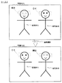
まず、図1、及び図2を参照しながら、以下で説明する実施形態に係る技術が目的とするところについて簡単に説明する。図1、図2は、連続撮影された被写体像の一例を模式的に示した説明図である。以下の説明において、図1の例をケース1、図2の例をケース2と呼ぶことにする。
[the purpose]
First, with reference to FIG. 1 and FIG. 2, a brief description will be given of a purpose of a technique according to an embodiment described below. FIG. 1 and FIG. 2 are explanatory diagrams schematically showing an example of a continuously captured subject image. In the following description, the example of FIG. 1 is referred to as
まず、図1を参照する。図1には、時刻t1に撮影された写真P(t1)と、時刻t2に撮影された写真P(t2)とが描画されている。但し、時刻t1、t2は、連続する撮影時刻である。また、写真P(t1)、P(t2)には、2つの被写体像(被写体A、被写体B)が撮像されている。ここでは、被写体A及び被写体Bの「瞬き」に注目する。 First, refer to FIG. In FIG. 1, a picture P (t1) taken at time t1 and a picture P (t2) taken at time t2 are drawn. However, times t1 and t2 are continuous shooting times. Further, two subject images (subject A and subject B) are captured in the photos P (t1) and P (t2). Here, attention is paid to the “blink” of the subject A and the subject B.
ケース1の場合、写真P(t1)に含まれる被写体Aは、瞬きをした瞬間に撮影されたものである。そのため、写真P(t1)に含まれる被写体Aに関しては、撮影者の意図に合致した状態ではない。但し、写真P(t1)に含まれる被写体Bは、瞬きをしておらず、撮影者の意図に合致した状態(OK)である。
In
このように、撮影者の意図に合致しない被写体像が含まれる写真P(t1)は、撮影者の意図に合致した写真ではない。一方、写真P(t2)に含まれる被写体A及び被写体Bは、瞬きをしておらず、撮影者の意図に合致した状態(OK)である。そのため、写真P(t2)は、撮影者の意図に合致した写真である。ケース1のように、連続撮影された複数枚の写真の中に、撮影者の意図に合致した写真(写真P(t2))が含まれている場合、撮影者は、意図に合致した写真P(t2)を選択すればよい。
Thus, the photograph P (t1) including the subject image that does not match the photographer's intention is not a photograph that matches the photographer's intention. On the other hand, the subject A and the subject B included in the photograph P (t2) do not blink and are in a state (OK) that matches the photographer's intention. Therefore, the photograph P (t2) is a photograph that matches the photographer's intention. When the photograph (photo P (t2)) that matches the photographer's intention is included in the plurality of continuously photographed photographs as in the
次に、図2を参照する。図2には、図1と同様に、時刻t1に撮影された写真P(t1)と、時刻t2に撮影された写真P(t2)とが描画されている。ケース2の場合も、時刻t1、t2は、連続する撮影時刻である。また、写真P(t1)、P(t2)には、2つの被写体像(被写体A、被写体B)が撮像されている。 Reference is now made to FIG. In FIG. 2, similarly to FIG. 1, a picture P (t1) taken at time t1 and a picture P (t2) taken at time t2 are drawn. Also in case 2, times t1 and t2 are continuous shooting times. Further, two subject images (subject A and subject B) are captured in the photos P (t1) and P (t2).
ケース2の場合も、写真P(t1)に含まれる被写体Aは、瞬きをした瞬間に撮影されたものである。そのため、写真P(t1)に含まれる被写体Aに関しては、撮影者の意図に合致した状態ではない。但し、写真P(t1)に含まれる被写体Bは、瞬きをしておらず、撮影者の意図に合致した状態(OK)である。つまり、撮影者の意図に合致しない被写体像が含まれる写真P(t1)は、撮影者の意図に合致した写真ではない。 In the case 2 as well, the subject A included in the photograph P (t1) was taken at the moment of blinking. Therefore, the subject A included in the photograph P (t1) is not in a state that matches the photographer's intention. However, the subject B included in the photograph P (t1) does not blink and is in a state (OK) that matches the photographer's intention. That is, the photograph P (t1) including the subject image that does not match the photographer's intention is not a photograph that matches the photographer's intention.
一方で、写真P(t2)に含まれる被写体Aは、瞬きをしておらず、撮影者の意図に合致した状態(OK)である。但し、写真P(t2)に含まれる被写体Bは、瞬きをした瞬間に撮影されたものである。そのため、写真P(t2)は、撮影者の意図に合致した写真ではない。ケース1のように、連続撮影された複数枚の写真の中に、撮影者の意図に合致した写真(写真P(t2))が含まれている場合、撮影者は、意図に合致した写真P(t2)を選択すればよい。しかし、ケース2の場合、この手法を用いることができない。
On the other hand, the subject A included in the photograph P (t2) does not blink and is in a state (OK) that matches the photographer's intention. However, the subject B included in the photograph P (t2) was taken at the moment of blinking. Therefore, the photograph P (t2) is not a photograph that matches the photographer's intention. When the photograph (photo P (t2)) that matches the photographer's intention is included in the plurality of continuously photographed photographs as in the
上記のように、短時間に複数回のシャッターを切ってコマ送りのように連続して撮影された写真の中に、撮影者の意図に合う写真が存在する場合には、その意図に合う写真をピックアップする手法が適用できる。しかし、上記の例と同様、撮影者の意図しない被写体像を含まない写真が連続撮影された写真の中に含まれていない場合、意図に合う写真をピックアップする手法を適用することができない。例えば、集合写真のように、多数の人物像が撮像範囲に含まれている場合、全員が瞬きをしていない瞬間を捕らえるのは難しく、ケース2のような状況になる確率が高い。 As mentioned above, if there is a photo that matches the photographer's intention among the photos that were shot continuously like a frame-by-frame with multiple shutter releases in a short time, the photo that suits the intention A method of picking up the image can be applied. However, as in the above example, when a photograph that does not include a subject image that is not intended by the photographer is not included in the continuously photographed photographs, it is not possible to apply a technique for picking up a photograph that matches the intention. For example, when a large number of human images are included in the imaging range, such as a group photo, it is difficult to capture the moment when everyone is not blinking, and there is a high probability that the situation as in Case 2 will occur.
こうした現状に鑑み、以下で説明する実施形態に係る技術は、ケース2のような場合でも、撮影者の意図に合致した写真を得ることができるようにするものである。但し、同実施形態に係る技術は、被写体の瞬きに対する対策として適用されるだけでなく、後述する応用例でも示すように、多種多様なケースに適用可能である。また、同実施形態に係る技術の適用範囲は写真に限定されるものではなく、例えば、放送データや映像データを構成する動画像フレームや種々の静止画像についても適用範囲に含まれる。但し、以下では、説明の都合上、連続撮影された「写真」と表記することにする。 In view of such a current situation, the technique according to the embodiment described below enables a photograph that matches the photographer's intention even in the case of Case 2 to be obtained. However, the technology according to the embodiment is not only applied as a measure against blinking of the subject, but can be applied to various cases as shown in application examples described later. In addition, the application range of the technology according to the embodiment is not limited to a photograph, and includes, for example, moving image frames and various still images constituting broadcast data and video data. However, in the following, for convenience of explanation, it will be referred to as “photographs” taken continuously.
<実施形態>
以下、本発明の一実施形態について説明する。本実施形態は、連続撮影された複数枚の写真を合成する技術に関する。但し、当該技術は、所定のパラメータを変化させながら連続的に撮影された複数枚の写真に対しても適用される。また、本実施形態は、写真が表示された画面上をユーザが擦ることにより、その擦る動作に応じて連続撮影された他の写真を合成処理する技術に関する。そのため、当該技術は、ユーザの操作体系に関する。
<Embodiment>
Hereinafter, an embodiment of the present invention will be described. The present embodiment relates to a technique for synthesizing a plurality of continuously photographed photographs. However, this technique is also applied to a plurality of photographs taken continuously while changing predetermined parameters. In addition, the present embodiment relates to a technique for synthesizing other photographs continuously photographed in accordance with the rubbing operation by the user rubbing on the screen on which the pictures are displayed. Therefore, the technique relates to a user operation system.
[原理説明]
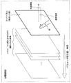
まず、図3を参照しながら、本実施形態の手法について原理説明を行う。図3は、本実施形態に係る技術の原理を説明するための原理説明図である。
[Principle explanation]
First, the principle of the method of the present embodiment will be described with reference to FIG. FIG. 3 is a principle explanatory diagram for explaining the principle of the technique according to the present embodiment.
図3には、タッチパネルと、連続撮影された複数枚の写真とが模式的に示されている。これらの写真は、パラメータを変化させながら連続して撮影されたものである。但し、連続撮影時に撮像機構に関するパラメータを変化させていなくても、1つのパラメータである「時間」が変化している点に注意されたい。撮像機構に関するパラメータとしては、例えば、被写界深度、エフェクト、逆光補正、フラッシュ等がある。 FIG. 3 schematically shows a touch panel and a plurality of continuously taken photographs. These photographs were taken continuously while changing the parameters. However, it should be noted that one parameter, “time”, is changing even if the parameters relating to the imaging mechanism are not changed during continuous shooting. Parameters relating to the imaging mechanism include, for example, depth of field, effects, backlight correction, flash, and the like.
被写界深度は、焦点距離、及び絞り値等に依存して決定されるものである。例えば、焦点距離が短くなればなるほど被写界深度は深くなり、さらに、絞りが絞り込まれるほど被写界深度が深くなる。エフェクトとしては、例えば、レンズフィルタや種々のデジタルフィルタによる効果を施すものや、任意の背景画を合成したり、写真全体をセピア色に変化させたりする効果を施すものがある。レンズフィルタによる効果としては、例えば、偏光フィルタ、減光フィルタ、色補正フィルタ、色彩強調フィルタ等がある。なお、フラッシュについては、例えば、点灯/消灯の切り替えや輝度の調整量がパラメータ値となる。 The depth of field is determined depending on the focal length, the aperture value, and the like. For example, the shorter the focal length, the deeper the depth of field, and the deeper the aperture, the deeper the depth of field. As effects, for example, there are those that apply an effect by a lens filter and various digital filters, and those that combine an arbitrary background image or change an entire photo to sepia. Examples of the effects of the lens filter include a polarizing filter, a neutral density filter, a color correction filter, and a color enhancement filter. For the flash, for example, switching between lighting / extinguishing and the amount of adjustment of the brightness are the parameter values.
これらのパラメータを変化させつつ連続して撮影された複数枚の写真は、図3の中で、パラメータの変化方向(経時方向)に沿って配列されている。実際には、撮影時刻の情報に基づいて写真データが整列されることにより、パラメータの変化方向に沿って写真データが整列される。但し、通常は、撮影時刻の情報に基づいて写真データが並べて管理されているため、ユーザに特別な操作が要求されない点に注意されたい。このように整列された写真データの先頭に位置する写真がタッチパネルに表示される。つまり、連続撮影された複数枚の写真の中で、最初に撮影された写真がタッチパネルに表示される。 A plurality of photographs taken continuously while changing these parameters are arranged along the parameter changing direction (time-lapse direction) in FIG. Actually, the photographic data is aligned based on the parameter change direction by aligning the photographic data based on the information of the photographing time. However, it should be noted that since the photo data is usually managed side by side based on the information of the photographing time, no special operation is required from the user. The photograph located at the head of the photograph data arranged in this way is displayed on the touch panel. In other words, the first photograph taken among a plurality of continuously photographed pictures is displayed on the touch panel.
ここで、ユーザは、タッチパネルに表示された写真を見ながらタッチパネルの表面を指で擦ることにより、指で擦った画素領域について、表示された写真と他の写真とを合成することができる。このとき、本実施形態では、ユーザにより指で擦られた位置又は領域、当該位置又は領域を指が往復した回数、押圧力、指の本数、又は指の移動速度等の摩擦情報が写真の合成処理に用いられる。当該合成処理においては、例えば、指が往復した回数又は押圧力等に応じて、よりパラメータ量の大きい写真が合成される。このとき、ユーザにより指で擦られた位置又は領域のみが合成される。そのため、ユーザは、簡単な操作で写真の一部分だけを合成処理することができる。 Here, the user can synthesize the displayed photograph with another photograph for the pixel region rubbed with the finger by rubbing the surface of the touch panel with a finger while viewing the photograph displayed on the touch panel. At this time, in this embodiment, friction information such as the position or area rubbed with the finger by the user, the number of times the finger reciprocated in the position or area, the pressing force, the number of fingers, or the moving speed of the finger is combined with the photograph. Used for processing. In the composition process, for example, a photograph with a larger parameter amount is composed according to the number of times the finger has reciprocated or the pressing force. At this time, only the position or area rubbed with the finger by the user is synthesized. Therefore, the user can combine only a part of the photograph with a simple operation.
例えば、図2に示したケース2の場合、タッチパネルには、写真P(t1)が表示されている。上記の通り、写真P(t1)は、被写体Aが瞬きしている点で撮影者の意図に合わないものである。一方、写真P(t2)は、被写体Bが瞬きしており、こちらの写真も撮影者の意図に沿うものではない。 For example, in the case 2 shown in FIG. 2, the photograph P (t1) is displayed on the touch panel. As described above, the photograph P (t1) does not match the photographer's intention in that the subject A blinks. On the other hand, in the photo P (t2), the subject B blinks, and this photo does not match the photographer's intention.
しかし、写真P(t1)に写っている被写体Aの一部(目の周囲)を写真P(t2)の被写体Aの一部(目の周囲)で置き換えれば、撮影者の意図に合致する写真が出来上がる。そこで、ユーザは、タッチパネルに表示された写真P(t1)を見ながら、被写体Aの一部(目の周囲)を指で擦る動作を行う。この動作により、写真P(t1)の中で擦られた部分だけが徐々に写真P(t2)に合成され、最終的に写真P(t2)に写っている被写体Aの一部に置き換えられる。その結果、被写体A、及び被写体Bがいずれも瞬きしていない所望の写真が得られる。 However, if a part of the subject A (around the eyes) in the photograph P (t1) is replaced with a part of the subject A (around the eyes) in the photograph P (t2), the photograph matches the photographer's intention. Is completed. Therefore, the user performs an operation of rubbing a part of the subject A (around the eyes) with a finger while looking at the photograph P (t1) displayed on the touch panel. By this operation, only the rubbed part in the picture P (t1) is gradually combined with the picture P (t2), and finally replaced with a part of the subject A shown in the picture P (t2). As a result, a desired photograph in which neither the subject A nor the subject B blinks is obtained.
このように、本実施形態に係る技術は、ユーザの擦る動作により、ユーザが意図する合成位置や合成範囲、或いは、合成度合い等を変更して、ユーザが行う一連の動作により合成画像を生成するというものである。また、ユーザが行う操作は、タッチパネルの表面を擦る動作だけであり、画像処理アプリケーション等とは比べものにならないほど簡単な操作で写真の合成処理が可能になる。つまり、本実施形態に係る技術は、このような利便性の高い操作体系を提供するものでもある。 As described above, the technique according to the present embodiment generates a composite image by a series of operations performed by the user by changing a composite position, a composite range, a composite degree, or the like intended by the user by a user's rubbing operation. That's it. Further, the user performs only the operation of rubbing the surface of the touch panel, and the photo composition process can be performed with a simple operation that is not comparable to an image processing application or the like. That is, the technology according to the present embodiment also provides such a highly convenient operation system.
なお、上記の説明の中で、タッチパネルは、表示手段、及び入力手段の一例として説明に用いたものである。また、タッチパネルを擦るための指以外の手段としては、例えば、スタイラス等が用いられることもある。さらに、タッチパネルの画面には、連続撮影された最初の写真が表示されていなくてもよく、例えば、ユーザが指定した撮影時点の写真や所定の撮影時点に対応する写真が表示されていてもよい。また、複数本の指で擦られた場合に、合成された写真が元に戻るように構成されていてもよい。このように、本実施形態はこれに限定されず、種々の変形が可能である。 In the above description, the touch panel is used as an example of display means and input means. Further, as means other than the finger for rubbing the touch panel, for example, a stylus or the like may be used. Furthermore, the first photograph taken continuously may not be displayed on the screen of the touch panel. For example, a photograph at a photographing time designated by a user or a photograph corresponding to a predetermined photographing time may be displayed. . Moreover, when it rubs with a several finger | toe, you may be comprised so that the synthesized photograph may return to the original. Thus, the present embodiment is not limited to this, and various modifications are possible.
以上、本実施形態の原理説明を行った。以下では、本実施形態に係る技術を実現するための具体的な画像処理装置100の機能構成及び一連の動作について説明する。これまで、具体性を強調するために合成処理対象として「写真」という表現を用いて説明してきたが、以下の説明の中では、より広範な意味を含む「画像」という表現を用いる。
The principle of this embodiment has been described above. Hereinafter, a specific functional configuration and a series of operations of the
[画像処理装置100の機能構成]
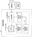
ここで、図4を参照しながら、本実施形態に係る画像処理装置100の機能構成について説明する。図4は、本実施形態に係る画像処理装置100の機能構成を示す説明図である。なお、図4には、画像処理装置100に対して連続撮影された写真データを提供する撮像装置200も描画されている。この撮像装置200及び画像処理装置100により、画像処理システムが形成される。
[Functional Configuration of Image Processing Apparatus 100]
Here, the functional configuration of the
図4に示すように、画像処理装置100は、主に、表示入力部110と、画像合成部130とにより構成される。
As shown in FIG. 4, the
(表示入力部110)
表示入力部110は、主に、表示部112と、摩擦位置検出部114とにより構成される。上記のタッチパネルは、表示入力部110の一例である。
(Display input unit 110)
The display input unit 110 mainly includes a
表示部112は、撮像装置200により撮影された画像を表示するためのディスプレイデバイスである。また、表示部112の機能は、図14に示すハードウェア資源のうち、出力部918により実現される。また、表示部112には、摩擦位置検出部114が設けられている。摩擦位置検出部114は、表示部112と一体に形成されていてもよいし、別体として形成されていてもよい。但し、摩擦位置検出部114は、表示部112の画面上に設けられ、表示部112に表示された画像が透過して見えるように構成されている。
The
摩擦位置検出部114は、ユーザにより擦られた位置を検出するものである。特に、摩擦位置検出部114は、表示部112の画面上に表示された画像の中で、どの位置又は領域がユーザにより擦られたかを検出するものである。また、摩擦位置検出部114は、ユーザにより擦られた際に掛かった押圧力を検知できるように構成されていてもよい。さらに、摩擦位置検出部114は、ユーザにより直接接触されていなくても、表示部112に近接した画面上の空間にユーザの指等が存在するのを検知し、摩擦位置として認識できる機能を有していてもよい。つまり、ここで言う摩擦位置は、ユーザが表示部112の画面上で空を描くように行った動作に対する位置情報を含むものであってもよい。
The
このようにして検出された摩擦位置の情報は、摩擦位置検出部114から画像合成部130の摩擦情報検出部132に入力される。
The information on the friction position thus detected is input from the friction
(画像合成部130)
画像合成部130は、主に、摩擦情報検出部132と、合成比率設定部134と、合成処理部136とにより構成される。なお、画像合成部130の機能は、例えば、図14に示すハードウェア資源のうち、ROM904、RAM906、記憶部920、又はリムーバブル記録媒体928に記録されたコンピュータプログラムに基づいてCPU902により実現されうる。
(Image composition unit 130)
The image composition unit 130 mainly includes a friction
(摩擦情報検出部132)
摩擦情報検出部132は、表示入力部110の摩擦位置検出部114により入力された摩擦位置の情報に基づいて種々の摩擦情報を検出する。この摩擦情報としては、例えば、ユーザに擦られた画素領域、当該画素領域の往復摩擦回数、摩擦の早さ、摩擦の方向、又は摩擦された軌跡の形状等が含まれる。
(Friction information detection unit 132)
The friction
摩擦情報検出部132は、例えば、摩擦位置検出部114から逐次検出される摩擦位置の情報を蓄積しておき、その蓄積された情報を解析することにより、これらの摩擦情報を検出することができる。摩擦情報検出部132により検出された摩擦情報は、合成比率設定部134に入力される。以下では、説明の都合上、摩擦情報として「摩擦回数」「画素領域」が検出されたものとして説明する。
For example, the friction
(合成比率設定部134)
合成比率設定部134は、摩擦情報検出部132により検出された摩擦情報に基づいて画像の合成比率を設定する。ここで言う画像の合成比率とは、表示部112に表示されている画像(以下、表示画像)における擦られた画素領域の画素値と、合成される画像(以下、被合成画像)の画素値とを合成する際の合成比率を意味している。例えば、合成比率設定部134は、摩擦回数が多くなるに連れて、被合成画像の重みが大きくなるように画素値の合成比率を設定する。但し、摩擦回数に応じて合成する画像を切り替える場合、合成比率は、1又は0に固定されたままである。
(Composite ratio setting unit 134)
The composition
ここで、合成比率の設定方法について、具体例を挙げて説明する。まず、撮像装置200により、3枚の画像(画像P(t1)、画像P(t2)、画像P(t3);t1<t2<t3)が撮影され、画像処理装置100に入力されているものとする。また、画像P(t1)が表示部112に表示されているものとする。このとき、ユーザにより画像P(t1)が表示された表示部112が擦られると、摩擦位置検出部114により摩擦位置が検出され、摩擦情報検出部132により摩擦回数が合成比率設定部134に入力される。
Here, a method for setting the composition ratio will be described with a specific example. First, three images (image P (t1), image P (t2), image P (t3); t1 <t2 <t3) are captured by the
摩擦回数が1回の場合、例えば、ユーザにより擦られた画像P(t1)の画素領域が持つ画素値D1と、画像P(t2)の画素領域が持つ画素値D2とが1:1で合成され、画素値D’=(D1+D2)/2が算出されるように合成比率が設定される。摩擦回数が2回の場合、例えば、ユーザにより擦られた画像P(t1)の画素領域が持つ画素値D1と、画像P(t2)の画素領域が持つ画素値D2とが1:2で合成され、画素値D’=(D1+2*D2)/3が算出されるように合成比率が設定される。このような構成にすることで、擦るに連れて表示画像がパラメータの大きい被合成画像に徐々に変化していく様子が表現できる。 When the number of times of friction is 1, for example, the pixel value D1 of the pixel area of the image P (t1) rubbed by the user and the pixel value D2 of the pixel area of the image P (t2) are combined at 1: 1. Then, the composition ratio is set so that the pixel value D ′ = (D1 + D2) / 2 is calculated. When the number of times of friction is 2, for example, the pixel value D1 of the pixel area of the image P (t1) rubbed by the user and the pixel value D2 of the pixel area of the image P (t2) are combined at 1: 2. Then, the composition ratio is set so that the pixel value D ′ = (D1 + 2 * D2) / 3 is calculated. With such a configuration, it is possible to express the display image gradually changing to a composite image having a large parameter as it is rubbed.
一方、摩擦回数に応じて合成する画像を切り替える場合は次のようになる。摩擦回数が1回の場合、ユーザにより擦られた画像P(t1)の画素領域が持つ画素値D1が、画像P(t2)の画素領域が持つ画素値D2に置き換えられる。つまり、その画素領域に対応する合成後の画素値D’はD’=D2になる。上記の表現を用いれば、画素値D1と画素値D2との間の合成比率が0:1ということになる。また、摩擦回数が2回の場合、ユーザにより擦られた画像P(t1)の画素領域が持つ画素値D1が、画像P(t3)の画素領域が持つ画素値D3に置き換えられる。つまり、その画素領域に対応する合成後の画素値D’はD’=D3になる。上記の表現を用いれば、画素値D1と画素値D3との間の合成比率が0:1ということになる。 On the other hand, when switching the image to be synthesized according to the number of frictions, it is as follows. When the number of times of friction is 1, the pixel value D1 of the pixel area of the image P (t1) rubbed by the user is replaced with the pixel value D2 of the pixel area of the image P (t2). That is, the combined pixel value D ′ corresponding to the pixel region is D ′ = D2. If the above expression is used, the synthesis ratio between the pixel value D1 and the pixel value D2 is 0: 1. When the number of frictions is 2, the pixel value D1 of the pixel area of the image P (t1) rubbed by the user is replaced with the pixel value D3 of the pixel area of the image P (t3). That is, the combined pixel value D ′ corresponding to the pixel region is D ′ = D3. If said expression is used, the synthetic | combination ratio between pixel value D1 and pixel value D3 will be 0: 1.
上記の設定方法は一例であり、本実施形態はこれに限定されるものではないが、このような設定方法を用いることにより、摩擦情報に応じた合成比率が設定されうる。また、画像の合成方法については後段において詳細に説明する。このようにして設定された合成比率は、合成処理部136に入力される。
The above setting method is an example, and the present embodiment is not limited to this. However, by using such a setting method, a composition ratio corresponding to friction information can be set. The image composition method will be described in detail later. The composition ratio set in this way is input to the
(合成処理部136)
合成処理部136は、連続撮影された画像群のうち、最初又は所定の撮影時点に対応する画像を表示部112に表示させる。その後、ユーザは、表示部112に表示された画像を見ながら表示部112の画面上を擦る動作を行う。この擦る動作に応じて摩擦情報が検出され、当該摩擦情報に応じて合成比率設定部134により合成比率が設定される。この合成比率が入力されると、合成処理部136は、合成比率設定部134により設定された合成比率に基づき、撮像装置200により連続撮影された画像を表示部112に表示させた画像に合成する。さらに、合成処理部136は、合成後の画像を表示部112に表示させ、再びユーザに提示する。
(Composition processing unit 136)
The
(画像合成処理の詳細説明)
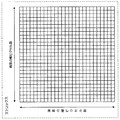
ここで、図5〜図9を参照しながら、上記の画像合成処理について、より詳細に説明する。図5は、画像のピクセル数に対応するマトリックスを示す説明図である。図6は、ブラシマトリックスの一例を示す説明図である。図7は、入力操作の一例を示す説明図である。図8は、深度マトリックスの一例を示す説明図である。
(Detailed explanation of image composition processing)
Here, the above-described image composition processing will be described in more detail with reference to FIGS. FIG. 5 is an explanatory diagram showing a matrix corresponding to the number of pixels of an image. FIG. 6 is an explanatory diagram illustrating an example of a brush matrix. FIG. 7 is an explanatory diagram illustrating an example of an input operation. FIG. 8 is an explanatory diagram illustrating an example of a depth matrix.
まず、図5を参照する。画像合成部130は、図5に示すマトリックスの情報を保持している。このマトリックスは、画像のピクセル数と同じサイズのデータ格納領域を示しており、例えば、各セルに深度の情報が保持される行列データである。ここで言う深度とは、どの画像がどれだけの割合で合成(表示)されているかを示す指標である。初め、このマトリックスには所定値が格納されており、ユーザによる摩擦動作に応じてマトリックスに格納された深度が更新される。この深度に応じて、画像合成部130により合成される被合成画像の撮影時点が決定されたり、表示画像に合成される被合成画像の比率が設定されたりする。 First, referring to FIG. The image composition unit 130 holds the matrix information shown in FIG. This matrix indicates a data storage area having the same size as the number of pixels of the image, and is, for example, matrix data in which depth information is held in each cell. The depth referred to here is an index indicating which image is synthesized (displayed) at what ratio. Initially, a predetermined value is stored in this matrix, and the depth stored in the matrix is updated according to the frictional motion by the user. In accordance with this depth, the shooting time of the combined image combined by the image combining unit 130 is determined, or the ratio of the combined image combined with the display image is set.
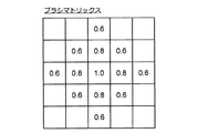
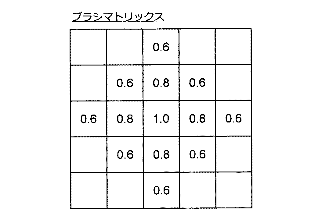
次いで、図6を参照する。図6は、ユーザにより擦られた画素領域に対応するマトリックス値を更新するためのブラシマトリックスである。つまり、このブラシマトリックスは、マトリックスの値に加算される深度を設定するためのものである。この例では、5ピクセル×5ピクセルのサイズを持つブラシマトリックスが設定されている。また、このブラシマトリックスは、中心の値が1.0であり、外側に向かって値が小さくなるように深度が設定されている。ユーザにより擦られた位置が検出されると、その検出位置の画素とブラシマトリックスの中心とが一致するように位置が調整され、ブラシマトリックスの値がマトリックスの値に加算される。 Reference is now made to FIG. FIG. 6 is a brush matrix for updating a matrix value corresponding to a pixel area rubbed by the user. That is, this brush matrix is for setting the depth added to the value of the matrix. In this example, a brush matrix having a size of 5 pixels × 5 pixels is set. Further, this brush matrix has a center value of 1.0, and the depth is set so that the value decreases toward the outside. When the position rubbed by the user is detected, the position is adjusted so that the pixel at the detected position matches the center of the brush matrix, and the value of the brush matrix is added to the value of the matrix.
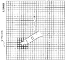
まず、図7に示すように、ある画素領域がユーザにより擦られる。図7には、ユーザの指により擦られた位置とマトリックスの位置との間の対応関係が分かるように両者が模式的に描画されている。実際、マトリックスは行列データであるから、図7のようにマトリックスが直接押圧されることはない。しかし、画像合成部130は、図7に示すイメージのように、ユーザが押圧した位置の情報を取得してマトリックス上の位置を認識しているのである。このようにしてユーザにより擦る動作が行われると、画像合成部130により、ブラシマトリックスに格納された深度がマトリックスの値に加算される。この様子を示したのが図8である。 First, as shown in FIG. 7, a certain pixel area is rubbed by the user. In FIG. 7, both are schematically drawn so that the correspondence between the position rubbed by the user's finger and the position of the matrix can be understood. Actually, since the matrix is matrix data, the matrix is not directly pressed as shown in FIG. However, the image composition unit 130 recognizes the position on the matrix by acquiring information on the position pressed by the user, as in the image shown in FIG. When the user performs a rubbing operation in this manner, the image synthesis unit 130 adds the depth stored in the brush matrix to the matrix value. This is shown in FIG.
図8の例は、マトリックスの各セルに初期値として深度10.0が格納されており、ユーザにより擦られた位置にブラシマトリックスの値が加算された状態のマトリックスを示したものである。図7に示すように、ある画素領域がユーザにより擦られると、画像合成部130により、その画素領域に合うようにブラシマトリックスの位置が調整される。そして、画像合成部130により、ブラシマトリックスの各セルに格納された深度の値が、その各セルに対応するマトリックスの各セルに格納された深度の値に加算される。図6に示すようにブラシマトリックスが設定されていると、加算後のマトリックスは、図8に示すようなものになる。 The example of FIG. 8 shows a matrix in which the depth 10.0 is stored in each cell of the matrix as an initial value, and the value of the brush matrix is added to the position rubbed by the user. As shown in FIG. 7, when a certain pixel area is rubbed by the user, the image composition unit 130 adjusts the position of the brush matrix so as to fit the pixel area. Then, the image composition unit 130 adds the depth value stored in each cell of the brush matrix to the depth value stored in each cell of the matrix corresponding to each cell. When the brush matrix is set as shown in FIG. 6, the matrix after the addition is as shown in FIG.
もし、ユーザにより繰り返し同じ画素領域が擦られると、その擦られた部分のマトリックスの値が繰り返し加算されていくことになる。そのため、摩擦回数が大きくなるに連れてマトリックスに格納された深度の値が大きくなる。また、ユーザが同じ画素領域に接触し続けた時間や、その画素領域を押圧した圧力に応じてブラシマトリックスの値が複数回加算されるように構成されていてもよい。さらに、ある画素領域をユーザが擦る際に、その摩擦速度が小さいほど又は大きいほど、ブラシマトリックスの加算回数が多くなるように構成されていてもよい。このような構成にすることで、画像合成部130は、様々な種類の摩擦情報に応じてマトリックスの値を制御することができるようになる。 If the same pixel region is rubbed repeatedly by the user, the matrix values of the rubbed portion are repeatedly added. Therefore, the depth value stored in the matrix increases as the number of frictions increases. Further, the brush matrix value may be added a plurality of times according to the time during which the user keeps touching the same pixel region or the pressure with which the pixel region is pressed. Furthermore, when the user rubs a certain pixel area, the brush matrix may be added more frequently as the friction speed is smaller or larger. With this configuration, the image composition unit 130 can control the matrix values in accordance with various types of friction information.
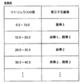
このようにして得られる画素毎の深度は、表示される画像の決定や合成比率の決定に利用される。これらの決定に際して、例えば、図9に示すような変換表が用いられる。図9の変換表は、表示する画像を決定するためのものである。この変換表は、マトリックスの値が含まれる数値範囲を示す欄と、その数値範囲に対応する画像の区分を示す欄とにより構成されている。 The depth for each pixel obtained in this way is used to determine the displayed image and the composition ratio. For these determinations, for example, a conversion table as shown in FIG. 9 is used. The conversion table in FIG. 9 is for determining an image to be displayed. This conversion table is composed of a column indicating a numerical range in which values of the matrix are included, and a column indicating an image classification corresponding to the numerical range.
例えば、ある画素に対応するマトリックスの値(深度)が11.0であった場合、この画素は、「画像1、画像2」に対応する数値範囲10.0〜20.0に含まれる。そのため、この画素の画素値は、互いに対応する画像1及び画像2の画素値を用いて算出される。また、画像1及び画像2の画素を合成する際の合成比率は、合成比率設定部134により、マトリックスの値に応じて決定される。深度が11.0の場合、画像1の画素値D1と画像2の画素値D2との間の合成比率は、例えば、D1:D2=9:1に決定される。従って、合成画像の画素値D’は、D’=0.9*D1+0.1*D2となる。
For example, when the value (depth) of the matrix corresponding to a certain pixel is 11.0, this pixel is included in the numerical value range 10.0 to 20.0 corresponding to “
画素値Dが3原色に対応するR,G,Bの値を持つ場合、画素値D1(R1,G1,B1)、及び画素値D2(R2,G2,B2)を合成した合成後の画素値D’(R’,G’,B’)は、下記の式(1)のように表現される。その結果、画像1及び画像2の中でユーザにより擦られた画素領域は、このようにしてアルファブレンドされて表示される。なお、YCbCrやCMYK等の他の色空間表現に対しても、同様に画素値を合成することで合成画像の画素値が算出される。
When the pixel value D has R, G, and B values corresponding to the three primary colors, the combined pixel value obtained by combining the pixel value D1 (R1, G1, B1) and the pixel value D2 (R2, G2, B2) D ′ (R ′, G ′, B ′) is expressed as in the following formula (1). As a result, the pixel areas rubbed by the user in the
ここで、再び図9に示した変換表に注目して頂きたい。図9に示した変換表の中で、マトリックスの値が数値範囲0.0〜10.0の場合、或いは、数値範囲が20.0〜30.0の場合、表示される画像がそれぞれ画像1、或いは、画像2のみとなるように設定されている。つまり、ユーザによる擦り動作が繰り返されてマトリックスの値が漸次大きくなっても、これらの数値範囲に加算後の深度が含まれている間、擦られている画素領域の画素値が被合成画像のもので固定された状態となる。この状態は、所謂「溜め」を表現したものである。
Attention should be paid again to the conversion table shown in FIG. In the conversion table shown in FIG. 9, when the value of the matrix is a numerical value range of 0.0 to 10.0, or when the numerical value range is 20.0 to 30.0, the displayed image is
例えば、図2に示したケース2の場合、ユーザは、時間的に後で撮影された写真P(t2)の一部分(被写体Aの目の周囲)だけをそのまま写真P(t1)と置き換えたいと考えるであろう。もし、上記の「溜め」が無い場合、ユーザは、表示される合成画像を確認しつつ、擦り動作を繰り返しながら写真P(t2)が単独で表示される一瞬を慎重に探ることになる。また、その一瞬を外してしまうと、画素値が合成されたものとなり、画質が低下してしまう。しかし、上記の「溜め」が設定されていれば、写真P(t2)単独で表示された後で、ある程度擦り動作を行っても画素値が変わらない。そのため、ユーザは、表示される画像を参照しながら擦り動作を繰り返し、写真P(t2)単独で表示された時点を容易に、且つ、安心して見つけることができるようになる。 For example, in the case 2 shown in FIG. 2, the user wants to replace only a part of the photograph P (t2) (around the eye of the subject A) taken later in time with the photograph P (t1). Would think. If there is no “reservoir” described above, the user carefully searches for a moment when the photograph P (t2) is displayed alone while repeating the rubbing operation while checking the displayed composite image. Further, if the moment is removed, the pixel values are synthesized and the image quality is degraded. However, if the “reservoir” is set, the pixel value does not change even if the rubbing operation is performed to some extent after the photograph P (t2) is displayed alone. Therefore, the user can easily and safely find the time point when the photograph P (t2) is displayed alone by repeating the rubbing operation while referring to the displayed image.
以上、画像合成処理の詳細について説明した。上記の通り、画像合成部130の合成比率設定部134及び合成処理部136により、撮像装置200で連続撮影された画像の一部がユーザの擦り動作に応じて合成される。この合成された画像は、表示入力部110の表示部112に入力され、ユーザに対して提示される。但し、表示部112には、合成処理部136により画像が合成される度に合成後の画像が表示される。
The details of the image composition processing have been described above. As described above, a part of the images continuously captured by the
以上説明したように、本実施形態に係る画像処理装置100は、ユーザによる摩擦動作に応じて、連続撮影された複数枚の画像を合成するというものである。特に、画像処理装置100は、摩擦情報に応じて合成される画像を切り替えたり、合成比率を調整したりする構成に特徴がある。上記の通り、画像処理装置100の構成を適用することで、ユーザによる摩擦動作に応じて画像の一部分だけが滑らかに合成されていく操作体系が実現され、ユーザは、簡単な操作で意図に合致した画像を得ることが可能になる。
As described above, the
[撮像装置200の機能構成]
ここで、図4を参照しながら、撮像装置200の機能構成について簡単に説明する。但し、撮像装置200の機能は、図15に示したハードウェア構成により実現される。
[Functional Configuration of Imaging Device 200]
Here, the functional configuration of the
撮像装置200が有する機能の中で、本実施形態において重要なのはパラメータ変更部210の機能である。パラメータ変更部210は、撮像装置200が連続撮影を実行する際に、制御可能な種々のパラメータを画像単位で変化させる機能を有している。パラメータ変更部210が制御するパラメータとしては、例えば、例えば、被写界深度、エフェクト、逆光補正、フラッシュ等がある。パラメータ変更部210により、これらのパラメータが徐々に変更されつつ、連続して被写体像が撮影されるのである。但し、パラメータの変更は、パラメータ変更部210により自動的に実行されてもよいし、ユーザにより手動で実行されてもよい。
Among the functions of the
[画像処理装置100の動作説明]
次に、図10を参照しながら、本実施形態に係る画像処理装置100の動作説明を行う。図10は、本実施形態に係る画像処理装置100の動作を模式的に示す説明図である。但し、ここでは人物写真の瞬きを補正する例を示して説明している。
[Description of Operation of Image Processing Apparatus 100]
Next, the operation of the
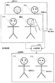
図10には、時刻t1に撮影された写真P(t1)と、時刻t2に撮影された写真P(t2)とが描画されている。時刻t1、t2は、連続する撮影時刻である。また、写真P(t1)、P(t2)には、2つの被写体像(被写体A、被写体B)が撮像されている。 In FIG. 10, a picture P (t1) taken at time t1 and a picture P (t2) taken at time t2 are drawn. Times t1 and t2 are continuous shooting times. Further, two subject images (subject A and subject B) are captured in the photos P (t1) and P (t2).
写真P(t1)に含まれる被写体Aは、瞬きをした瞬間に撮影されたものである。一方、写真P(t1)に含まれる被写体Bは、瞬きをしておらず、撮影者の意図に合致した状態(OK)である。また、写真P(t2)に含まれる被写体Aは、瞬きをしておらず、撮影者の意図に合致した状態(OK)である。一方、写真P(t2)に含まれる被写体Bは、瞬きをした瞬間に撮影されたものである。この場合、ユーザは、写真P(t2)に写っている被写体Bの目の部分を写真P(t1)のもので置き換えたいと考えるであろう。 The subject A included in the photo P (t1) was taken at the moment of blinking. On the other hand, the subject B included in the photograph P (t1) does not blink and is in a state (OK) that matches the photographer's intention. In addition, the subject A included in the photograph P (t2) does not blink, and is in a state (OK) that matches the photographer's intention. On the other hand, the subject B included in the photograph P (t2) was taken at the moment of blinking. In this case, the user will want to replace the eye portion of the subject B in the photo P (t2) with that of the photo P (t1).
このとき、ユーザは、図10に示すように、写真P(t2)に写っている被写体Bの目の周囲を擦るだけで、その摩擦領域に対応する写真P(t1)の画像を合成することができる。つまり、ユーザにより写真P(t2)の画素領域が擦られると、画像処理装置100は、その画素領域に対応する写真P(t2)及び写真P(t1)の画像を合成する(S100)。このような合成処理により、ユーザが所望するように、被写体Aも被写体Bも瞬きしていない合成画像が生成されるのである。
At this time, as shown in FIG. 10, the user simply rubs around the eyes of the subject B in the photo P (t2), and synthesizes the image of the photo P (t1) corresponding to the friction area. Can do. That is, when the pixel area of the photograph P (t2) is rubbed by the user, the
このように、ユーザは、瞬きをしてしまっている人物の目の周りを擦ることで、擦った部分だけ時間を進めることができる。このように画像全体ではなく、こすった部分のみを変化させることで、ユーザの意図した位置や範囲だけ深度を変化させることができる。 In this way, the user can advance the time by rubbing around the eyes of the blinking person. In this way, by changing only the rubbed portion, not the entire image, the depth can be changed only by the position and range intended by the user.
(合成処理S100の詳細)
ここで、図11を参照しながら、画像処理装置100による合成処理S100の流れについて、より詳細に説明する。図11は、本実施形態に係る画像処理装置100による合成処理の流れを示す説明図である。ここで示す一連の処理は、画像処理装置100が有する機能構成の中で、主に、画像合成部130の機能により実現される。
(Details of composition processing S100)
Here, the flow of the composition processing S100 performed by the
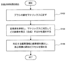
図11に示すように、まず、画像合成部130は、ユーザにより擦られた位置の画素領域にブラシマトリックスの位置を合わせ、ブラシマトリックスの各セルに格納された深度値をマトリックスの値に加算する(S102)。次いで、画像合成部130は、変換表を参照してマトリックスの値に対応する画像を選択することで、どの画像を合成(表示)するかを選択する(S104)。次いで、画像合成部130は、マトリックスの値に基づいて、ユーザにより擦られた画素領域の画素値を算出し、合成後の表示画像を構成する画素値として該当するピクセルを埋め(S106)、一連の処理を終了する。これらの処理により、ユーザの摩擦動作に応じた合成画像が生成される。 As shown in FIG. 11, first, the image composition unit 130 aligns the position of the brush matrix with the pixel area rubbed by the user, and adds the depth value stored in each cell of the brush matrix to the matrix value. (S102). Next, the image composition unit 130 selects which image is to be composed (displayed) by referring to the conversion table and selecting an image corresponding to the matrix value (S104). Next, the image composition unit 130 calculates the pixel value of the pixel region rubbed by the user based on the matrix value, fills the corresponding pixel as the pixel value constituting the composited display image (S106), and a series of Terminate the process. By these processes, a composite image corresponding to the user's friction motion is generated.
[応用例1:花火撮影]
次に、図12A〜図12Cを参照しながら、本実施形態の一応用例について述べる。図12A〜図12Cは、本実施形態に係る技術を花火撮影の場面に適用した場合の例を示す説明図である。ここで示す花火撮影の場面は、撮影者が意図する被写体像が時間差で現れる場合の例である。このように、被写体の状態を制御できないような場面に対しても、本実施形態に係る画像処理装置100は好適に用いられる。
[Application Example 1: Fireworks shooting]
Next, an application example of the present embodiment will be described with reference to FIGS. 12A to 12C. FIG. 12A to FIG. 12C are explanatory diagrams illustrating an example when the technique according to the present embodiment is applied to a scene of shooting fireworks. The fireworks shooting scene shown here is an example in the case where the subject image intended by the photographer appears with a time difference. As described above, the
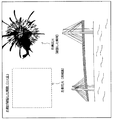
図12A〜図12Cは、2つの花火が破裂する瞬間を狙って連続的に撮影された画像を模式的に示したものである。なお、これらの一連の画像は、左側花火が最初に破裂し、その数秒後に右側花火が破裂した状態を撮影したものである。 FIG. 12A to FIG. 12C schematically show images continuously shot aiming at the moment when two fireworks burst. In addition, these series of images are images of a state where the left-side fireworks burst first, and the right-side fireworks burst several seconds later.
まず、図12Aを参照する。図12Aの撮影時点は、左側花火が破裂した瞬間である。左側花火については、撮影者の意図した通り、花火が最大に開いた状態の撮影が出来ている。しかし、この撮影時点では、右側花火は破裂前であり、撮影者の意図しているものよりも花火の直径が小さい。 First, refer to FIG. 12A. The shooting time point in FIG. 12A is the moment when the left-side fireworks burst. As for the fireworks on the left side, as the photographer intended, it was possible to shoot with the fireworks fully open. However, at this point in time, the right fireworks are before the explosion, and the fireworks diameter is smaller than what the photographer intended.
次に、図12Bを参照する。図12Bの撮影時点は、右側花火が破裂した瞬間である。右側花火については、撮影者の意図した通り、花火が最大に開いた状態の撮影が出来ている。しかし、この撮影時点では、左側花火が既に消滅してしまっている。そこで、撮影者は、図12Aの画像に写っている右側花火を図12Bに写っている右側花火で置き換えたいと考えるであろう。そこで、擦った部分だけ時間を進めることができる本実施形態の技術が用いられる。 Reference is now made to FIG. The shooting time point in FIG. 12B is the moment when the right fireworks burst. As for the fireworks on the right side, as the photographer intended, it was possible to shoot with the fireworks fully open. However, at the time of this shooting, the fireworks on the left side have already disappeared. Therefore, the photographer will want to replace the right fireworks shown in the image of FIG. 12A with the right fireworks shown in FIG. 12B. Therefore, the technique of the present embodiment that can advance the time only by the rubbed portion is used.
まず、撮影者は、図12Aに示した画像の中で右側花火を囲った枠内で擦る操作を行う。すると、擦られた枠内だけ時間が進むため、徐々に図12Bの右側花火の画像が合成されて表示されてくる。さらに擦ると、図12Cに示すように、図12Bに示した右側花火の画像が完全に合成され、左側花火と右側花火が共に破裂した瞬間の状態にある合成画像が生成される。本来、時間差で破裂する2つの花火が同時に破裂する瞬間というのは捉えられないが、本実施形態の技術を用いると、そのような合成画像が容易に生成できるようになるのである。 First, the photographer performs an operation of rubbing within the frame surrounding the right fireworks in the image shown in FIG. 12A. Then, since the time advances only within the rubbed frame, the image of the right fireworks in FIG. 12B is gradually synthesized and displayed. When further rubbing, as shown in FIG. 12C, the image of the right fireworks shown in FIG. 12B is completely synthesized, and a composite image in a state where the left fireworks and the right fireworks burst together is generated. Originally, it is not possible to capture the moment when two fireworks bursting at a time difference burst at the same time. However, using the technique of this embodiment, such a composite image can be easily generated.
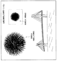
[応用例2:風景撮影]
次に、図13を参照しながら、本実施形態の一応用例について述べる。図13は、本実施形態に係る技術を風景撮影の場面に適用した場合の例を示す説明図である。ここで示す風景撮影の場面は、手前と奥とに被写体が存在し、手前と奥とに対して同時にフォーカスを合わせられない場合の例である。このように、どうしても撮影が困難な場面に対しても、本実施形態に係る画像処理装置100は好適に用いられる。
[Application example 2: landscape photography]
Next, an application example of this embodiment will be described with reference to FIG. FIG. 13 is an explanatory diagram showing an example in which the technology according to the present embodiment is applied to a scene shooting scene. The scene shooting scene shown here is an example in which there are subjects in front and back, and the front and back cannot be focused simultaneously. As described above, the
図13には、写真P(t1)、及び写真P(t2)が示されている。写真P(t1)は、奥にフォーカスが合うように撮影された写真である。一方、写真P(t2)は、手前にフォーカスが合うように撮影された写真である。風景を撮影する場合、奥の建物や山等にフォーカスを合わせると、手前の木々の葉等にはフォーカスが合わなくなる。逆に、手前の木々の葉等にフォーカスを合わせると、奥の建物や山等にはフォーカスが合わなくなる。このような場面においても、撮影者は、奥と手前とに共にフォーカスが合った画像を撮影したいと考えるであろう。そこで、擦った部分だけパラメータ(フォーカス)を移動することができる本実施形態の技術が用いられる。 FIG. 13 shows a photograph P (t1) and a photograph P (t2). The photograph P (t1) is a photograph taken so that the focus is in the back. On the other hand, the photograph P (t2) is a photograph taken so that the front is in focus. When shooting a landscape, focusing on a building or mountain in the back makes it impossible to focus on the leaves of the trees in the foreground. On the other hand, when focusing on the leaves of the trees in the foreground, the building and mountains in the back will not be focused. Even in such a scene, the photographer will want to shoot an image in which the back and front are both in focus. Therefore, the technique of the present embodiment that can move the parameter (focus) only by the rubbed portion is used.
まず、撮影者は、被写界震度を変化させながら連続撮影を行う。そして、撮影者は、写真P(t1)の中で手前の被写体を囲った枠内で擦る操作を行う。すると、擦られた枠内だけ被写界震度が進むため、徐々に写真P(t2)の画像が合成されて表示されてくる。さらに擦ると、図13に合成画像として示した通り、写真P(t2)に含まれる手前の画像が完全に合成され、奥の被写体と手前の被写体とに対して共にフォーカスが合った合成画像が生成される。本来、奥と手前とに同時にフォーカスが合った画像というのは得られないが、本実施形態の技術を用いることにより、そのような合成画像が容易に生成できるようになるのである。 First, the photographer performs continuous shooting while changing the field seismic intensity. Then, the photographer performs an operation of rubbing within the frame surrounding the front subject in the photograph P (t1). Then, since the field seismic intensity advances only within the rubbed frame, the image of the photograph P (t2) is gradually synthesized and displayed. Further rubbing, as shown as a composite image in FIG. 13, the foreground image included in the photograph P (t2) is completely combined, and a composite image in which both the back subject and the foreground subject are in focus is obtained. Generated. Originally, it is not possible to obtain an image in which the back and front are simultaneously focused, but by using the technique of this embodiment, such a composite image can be easily generated.
以上、本実施形態に係る2つの応用例を示した。もちろん、本実施形態の適用範囲はこれに限定されず、摩擦情報の種類やパラメータの種類に応じて様々な応用が可能である。 The two application examples according to the present embodiment have been described above. Of course, the application range of the present embodiment is not limited to this, and various applications are possible according to the type of friction information and the type of parameter.
[画像処理装置100のハードウェア構成例]
上記の画像処理装置100が有する各構成要素の機能は、例えば、図15に示すハードウェア構成を有する情報処理装置により、上記の機能を実現するためのコンピュータプログラムを用いて実現することが可能である。図15は、上記の画像処理装置100の各構成要素が有する機能を実現することが可能な情報処理装置のハードウェア構成を示す説明図である。この情報処理装置の形態は任意であり、例えば、パーソナルコンピュータ、携帯電話、PHS(Personal Handy−phone System)、PDA(Personal Digital Assistant)等の携帯情報端末、ゲーム機、又は各種の情報家電等の形態がこれに含まれる。
[Hardware Configuration Example of Image Processing Apparatus 100]
The function of each component included in the
図15に示すように、前記の情報処理装置は、主に、CPU(Central Processing Unit)902と、ROM(Read Only Memory)904と、RAM(Random Access Memory)906と、ホストバス908と、ブリッジ910と、外部バス912と、インターフェース914と、入力部916と、出力部918と、記憶部920と、ドライブ922と、接続ポート924と、通信部926とにより構成される。
As shown in FIG. 15, the information processing apparatus mainly includes a CPU (Central Processing Unit) 902, a ROM (Read Only Memory) 904, a RAM (Random Access Memory) 906, a
CPU902は、例えば、演算処理装置又は制御装置として機能し、ROM904、RAM906、記憶部920、又はリムーバブル記録媒体928に記録された各種プログラムに基づいて各構成要素の動作全般又はその一部を制御する。ROM904は、例えば、CPU902に読み込まれるプログラムや演算に用いるデータ等を格納する。RAM906は、例えば、CPU902に読み込まれるプログラムや、そのプログラムを実行する際に適宜変化する各種パラメータ等を一時的又は永続的に格納する。これらの構成要素は、例えば、高速なデータ伝送が可能なホストバス908によって相互に接続されている。また、ホストバス908は、例えば、ブリッジ910を介して比較的データ伝送速度が低速な外部バス912に接続されている。
The
入力部916は、例えば、マウス、キーボード、タッチパネル、ボタン、スイッチ、及びレバー等の操作手段である。また、入力部916は、赤外線やその他の電波を利用して制御信号を送信することが可能なリモートコントロール手段(所謂、リモコン)であってもよい。なお、入力部916は、上記の操作手段を用いて入力された情報を入力信号としてCPU902に伝送するための入力制御回路等により構成されている。
The
出力部918は、例えば、CRT(Cathode Ray Tube)、LCD(Liquid Crystal Display)、PDP(Plasma DisplayPanel)、又はELD(Electro−Luminescence Display)等のディスプレイ装置、スピーカ、ヘッドホン等のオーディオ出力装置、プリンタ、携帯電話、又はファクシミリ等、取得した情報を利用者に対して視覚的又は聴覚的に通知することが可能な装置である。
The
記憶部920は、各種のデータを格納するための装置であり、例えば、ハードディスクドライブ(HDD;Hard Disk Drive)等の磁気記憶デバイス、半導体記憶デバイス、光記憶デバイス、又は光磁気記憶デバイス等により構成される。
The
ドライブ922は、例えば、磁気ディスク、光ディスク、光磁気ディスク、又は半導体メモリ等のリムーバブル記録媒体928に記録された情報を読み出し、又はリムーバブル記録媒体928に情報を書き込む装置である。リムーバブル記録媒体928は、例えば、DVDメディア、Blu−rayメディア、HD DVDメディア、コンパクトフラッシュ(CF;Compact Flash)(登録商標)、メモリースティック、又はSDメモリカード(Secure Digital memory card)等である。もちろん、リムーバブル記録媒体928は、例えば、非接触型ICチップを搭載したICカード(Integrated Circuit Card)、又は電子機器等であってもよい。
The
接続ポート924は、例えば、USB(Universal Serial Bus)ポート、IEEE1394ポート、SCSI(Small Computer System Interface)、RS−232Cポート、又は光オーディオ端子等のような外部接続機器930を接続するためのポートである。外部接続機器930は、例えば、プリンタ、携帯音楽プレーヤ、デジタルカメラ、デジタルビデオカメラ、又はICレコーダ等である。
The
通信部926は、ネットワーク932に接続するための通信デバイスであり、例えば、有線又は無線LAN(Local Area Network)、Bluetooth(登録商標)、又はWUSB(Wireless USB)用の通信カード、光通信用のルータ、ADSL(Asymmetric Digital Subscriber Line)用のルータ、又は各種通信用のモデム等である。また、通信部926に接続されるネットワーク932は、有線又は無線により接続されたネットワークにより構成され、例えば、インターネット、家庭内LAN、赤外線通信、可視光通信、放送、又は衛星通信等である。
The
[撮像装置200のハードウェア構成例]
次いで、上記の撮像装置200のハードウェア構成例について説明する。上記の撮像装置200が有する各構成要素の機能は、例えば、図15に示すハードウェア構成により実現することが可能である。図15は、上記の撮像装置200の各構成要素が有する機能を実現することが可能なハードウェア構成の一例を示す説明図である。
[Hardware Configuration Example of Imaging Device 200]
Next, a hardware configuration example of the
図15に示すように、撮像装置200は、主に、制御部(例えば、CPU;Central Processing Unit)802と、位置取得部804と、RAM(Random Access Memory)806と、ROM(Read Only Memory)808と、バス810と、撮像部812と、画像処理部814と、表示部816と、記憶媒体(例えば、Flash Memory等)818とにより構成される。
As illustrated in FIG. 15, the
図中には明示しないが、ユーザによる操作を受け付ける入力部をさらに備えていてもよい。この入力部の機能は、例えば、マウス、キーボード、タッチパネル、ボタン、スイッチ、及びレバー等の操作手段により実現される。また、入力部は、赤外線やその他の電波、或いは、光波等を利用して制御信号を送信することが可能なリモートコントロール手段(所謂、リモコン)であってもよい。 Although not clearly shown in the figure, an input unit that receives an operation by the user may be further provided. The function of this input part is implement | achieved by operation means, such as a mouse | mouth, a keyboard, a touch panel, a button, a switch, and a lever, for example. The input unit may be remote control means (so-called remote controller) capable of transmitting a control signal using infrared rays, other radio waves, or light waves.
制御部802は、例えば、CPU等により実現され、RAM806、ROM808、又は記録媒体818等に記録された各種プログラムに基づいて各構成要素の動作全般又はその一部を制御する。ROM808は、例えば、制御部802に読み込まれるプログラムや演算に用いるデータ等を格納する。RAM806は、例えば、制御部802に読み込まれるプログラムや、そのプログラムを実行する際に適宜変化する各種パラメータ等を一時的又は永続的に格納する。これらの構成要素は、例えば、高速なデータ伝送が可能なバス810によって相互に接続されている。
The
位置取得部804は、撮像装置の位置情報を取得する手段である。位置情報取得部804は、例えば、通信可能な基地局にアクセスして当該基地局がカバーするエリアの情報を位置情報として取得してもよいし、或いは、測位用の衛星システム(GPS;Global Positioning System)等から位置情報を取得してもよい。位置情報としては、例えば、撮像装置200が位置する緯度、経度、又はエリアを特定可能な情報である。
The
撮像部812は、光学系を介して被写体の像を取得する手段である。撮像部812は、主に、レンズ822と、CCD(Charge Coupled Device)824と、AF制御部826と、AE制御部828とにより構成される。
The
レンズ822は、光学系を構成し、被写体により反射された光をCCD824に集光する。CCD824は、半導体素子により構成され、レンズ822により集光された光を各素子で受光し、その受光した光を光電変換して出力する固体撮像素子である。CCD824は、各素子が受光した光の強度に応じて電気信号を出力するため、その電気信号に基づいて画像信号を形成することができる。尚、上記撮像装置200は、CCD824に代えて、他の半導体素子により形成されたイメージセンサーを利用していてもよい。AF制御部826は、ピントを自動的に調整するためのオートフォーカス機構である。また、AE制御部828は、シャッター速度や絞り値を自動的に調整するための自動露出(AE;Automatic Exposure)制御機構である。
The
画像処理部814は、CCD824により出力された画像信号を表示部816で表示可能な画像データの形式に変換することができる。例えば、画像処理部814は、当該画像信号をBMP、GIF、JPEG、PICT、又はPING等の符号化形式に対応する画像データに変換することができる。また、画像処理部814は、画像データのサイズを変更したり、輝度や色調を調整したり、或いは、ガンマ補正やシャープネスの調整等をしたりする。さらに、画像処理部814は、撮像部812により連続して撮影された複数の画像信号から動画像データを生成することもできる。
The
表示部816は、例えば、LCD(Liquid Crystal Display)、PDP(Plasma DisplayPanel)、又はELD(Electro−Luminescence Display)等のディスプレイ装置であり、取得した情報を利用者に対して視覚的に通知することが可能な装置である。
The
記録媒体818は、磁気ディスク、光ディスク、光磁気ディスク、又は半導体メモリ等により構成される。例えば、記録媒体818は、DVDメディア、Blu−rayメディア、HD DVDメディア、コンパクトフラッシュ(登録商標)(CF;CompactFlash)、メモリースティック、SDメモリカード(Secure Digital memory card)、又はHDD(Hard Disk Drive)等である。また、撮像装置200は、記録媒体818として、例えば、非接触型ICチップを搭載したICカード(Integrated Circuit Card)や電子機器等を利用するように構成されていてもよい。
The
[まとめ]
最後に、本実施形態の画像処理装置が有する機能構成と、当該機能構成が奏する作用効果について簡単に纏める。
[Summary]
Finally, the functional configuration of the image processing apparatus according to the present embodiment and the operational effects achieved by the functional configuration will be briefly summarized.
まず、本実施形態に係る画像処理装置の機能構成は次のように表現することができる。 First, the functional configuration of the image processing apparatus according to the present embodiment can be expressed as follows.
当該画像処理装置は、連続して撮影された画像群に含まれる第1画像が表示される表示画面と、ユーザにより擦られた前記表示画面上の摩擦位置を検出する摩擦位置検出部と、前記摩擦位置に対応する前記第1画像の画素領域と、前記画像群に含まれる第2画像の画素領域とを合成する画像合成部とを備える。但し、前記画像合成部は、前記ユーザにより擦られた摩擦量が大きくなるに連れて前記第1画像と前記第2画像との間の撮影時間差が大きくなるように前記第1画像に合成される第2画像を切り替える機能を有する。 The image processing apparatus includes a display screen on which a first image included in continuously captured images is displayed, a friction position detection unit that detects a friction position on the display screen rubbed by a user, An image combining unit configured to combine the pixel region of the first image corresponding to the friction position and the pixel region of the second image included in the image group; However, the image synthesizing unit synthesizes the first image so that a photographing time difference between the first image and the second image increases as the friction amount rubbed by the user increases. A function of switching the second image;
このように、上記の画像処理装置は、連続して撮影された画像群に含まれる第1画像を表示画面に表示する機能を有する。第1画像としては、例えば、画像群に含まれる画像の中で撮影時点が最も新しいものが選択されるように構成される。また、上記の画像処理装置は、摩擦位置検出部により、ユーザにより擦られた前記表示画面上の摩擦位置を検出する機能を有する。摩擦位置検出部により摩擦位置が検出されることで、ユーザにより指定された画素領域が特定される。 As described above, the image processing apparatus has a function of displaying the first image included in the continuously photographed image group on the display screen. As the first image, for example, an image having the newest shooting time is selected from among images included in the image group. Further, the image processing apparatus has a function of detecting a friction position on the display screen rubbed by a user by a friction position detection unit. When the friction position is detected by the friction position detection unit, the pixel region designated by the user is specified.
さらに、上記の画像処理装置は、画像合成部により、前記摩擦位置に対応する前記第1画像の画素領域と、前記画像群に含まれる第2画像の画素領域とを合成する。このように構成されることで、撮影時点が異なる第2画像の一部が第1画像に合成される。このとき、ユーザにより指定された画素領域のみが第1画像に合成されるため、実際には撮影が困難な画像を生成することも可能になる。さらに、画像合成部により実行される合成処理は、ユーザによる摩擦動作により実現されるため、利便性の高い簡単な操作体系が提供される。特に、ユーザが画素領域を指定する操作、合成割合の設定操作、被合成画像の選択操作が一連の摩擦動作のみで実現できるため、格別に高い利便性が提供される。 Furthermore, the image processing apparatus combines the pixel region of the first image corresponding to the friction position and the pixel region of the second image included in the image group by an image combining unit. By being configured in this way, a part of the second image with different shooting time points is synthesized with the first image. At this time, since only the pixel region designated by the user is combined with the first image, it is possible to generate an image that is actually difficult to shoot. Furthermore, since the compositing process executed by the image compositing unit is realized by a friction operation by the user, a simple operation system with high convenience is provided. In particular, since the user can specify the pixel area, the composition ratio setting operation, and the composite image selection operation by only a series of frictional operations, exceptionally high convenience is provided.
また、上記の画像合成部は、前記ユーザにより擦られた摩擦量が大きくなるに連れて前記第1画像と前記第2画像との間の撮影時間差が大きくなるように前記第1画像に合成される第2画像を切り替える。このような構成にすることで、ユーザは、擦る動作を繰り返すことにより被合成画像を順次切り替えていくことが可能になる。その結果、被合成画像の切り替え処理についても一連の摩擦動作に組み込まれ、さらに利便性の高い操作体系が実現されるのである。 Further, the image composition unit composes the first image so that a photographing time difference between the first image and the second image increases as the friction amount rubbed by the user increases. Switch the second image. With this configuration, the user can sequentially switch the synthesized images by repeating the rubbing operation. As a result, the composite image switching process is also incorporated into a series of friction operations, and a more convenient operation system is realized.
また、前記画像合成部は、前記摩擦量が大きくなるに連れて前記第1画像に対する前記第2画像の合成比率を増加させ、前記摩擦量が所定の閾値を超過した段階で前記第2画像を前記第1画像からの撮影時間差がより大きい画像に切り替えるように構成されていてもよい。このように構成されることで、被合成画像の切り替え処理、及び表示画像と被合成画像との合成比率の調整処理が一連の摩擦動作に応じて実現されるようになる。つまり、連続的な摩擦動作により、表示画像から被合成画像へと合成画像がシームレスに変化していくことになる。その結果、ユーザは、より直感的な処理により合成画像を生成できるようになる。 The image composition unit increases the composition ratio of the second image to the first image as the friction amount increases, and the second image is displayed when the friction amount exceeds a predetermined threshold. It may be configured to switch to an image having a larger photographing time difference from the first image. With this configuration, the process for switching the combined image and the process for adjusting the composite ratio between the display image and the combined image are realized according to a series of friction operations. In other words, the composite image seamlessly changes from the display image to the composite image by the continuous friction operation. As a result, the user can generate a composite image by a more intuitive process.
また、前記画像合成部は、前記摩擦量が所定の閾値を所定量だけ超過するまで前記画素領域に切り替え前の前記第2画像を表示し、当該所定量を超過した段階で前記第2画像を切り替えるように構成されていてもよい。このように構成されることで、第1画像の一部が第2画像に完全に切り替わった後、擦り動作が継続されたとしても所定時間だけ第2画像が切り替わらないため、その完全に切り替わったタイミングを容易に見つけることができるようになる。その結果、第1画像の一部を第2画像に完全に置き換えた画像を意図している場合に、「溜め」がある分だけ正確にタイミングを捉えることができると共に、ユーザが安心して擦り動作を進めることができるようになる。 The image composition unit displays the second image before switching in the pixel area until the friction amount exceeds a predetermined threshold by a predetermined amount, and the second image is displayed when the predetermined amount is exceeded. It may be configured to switch. With this configuration, after a part of the first image is completely switched to the second image, the second image is not switched for a predetermined time even if the rubbing operation is continued. You will be able to find the timing easily. As a result, when an image in which a part of the first image is completely replaced with the second image is intended, the timing can be accurately captured by the amount of “reservoir”, and the user can rub with confidence. Will be able to proceed.
また、前記摩擦量は、前記画素領域が摩擦された回数、摩擦時の押圧力、摩擦方向、及び摩擦早さの中から選択される1つの量又は複数の組み合わせにより決定される量であってもよい。さらに、前記画像群は、撮影時に変更可能な任意のパラメータを変化させながら連続して撮影された複数の画像であってもよい。そして、前記パラメータは、被写界深度、画像エフェクト、又はフラッシュを制御するための制御パラメータであってもよい。但し、上記の画像処理装置の構成は、これらの例に限定されず、画像群を撮影する撮像装置の機能や構成に応じて、種々の変形が可能である。 The friction amount is an amount determined by one amount or a combination of plural selected from the number of times the pixel area is rubbed, the pressing force during friction, the friction direction, and the friction speed. Also good. Furthermore, the image group may be a plurality of images that are continuously captured while changing arbitrary parameters that can be changed at the time of capturing. The parameter may be a control parameter for controlling a depth of field, an image effect, or a flash. However, the configuration of the above-described image processing apparatus is not limited to these examples, and various modifications can be made according to the function and configuration of the imaging apparatus that captures an image group.
[効果]
ここで、本実施形態を適用することにより得られる効果について簡単に纏める。但し、本実施形態の各構成により得られる具体的な効果については、これまでの説明の中で既に述べている。そのため、ここで述べるのは、これらの具体的な効果を纏めたものである。まず、上記の実施形態に係る技術を用いると、連続撮影した画像を容易な操作体系で合成することが可能になるという効果が得られる。また、ユーザが意図する位置又は範囲や合成度合いを一連の摩擦動作により変化させて画像を合成することが可能になるという効果が得られる。さらに、実際には撮影が困難な画像を容易に生成することが可能になるという効果が得られる。
[effect]
Here, the effects obtained by applying this embodiment will be briefly summarized. However, specific effects obtained by each configuration of the present embodiment have already been described in the above description. Therefore, what is described here is a summary of these specific effects. First, when the technique according to the above-described embodiment is used, an effect that it is possible to synthesize continuously captured images with an easy operation system is obtained. Further, it is possible to obtain an effect that an image can be synthesized by changing the position or range intended by the user or the synthesis degree by a series of frictional operations. Furthermore, it is possible to easily generate an image that is actually difficult to shoot.
以上、添付図面を参照しながら本発明の好適な実施形態について説明したが、本発明は係る例に限定されないことは言うまでもない。当業者であれば、特許請求の範囲に記載された範疇内において、各種の変更例または修正例に想到し得ることは明らかであり、それらについても当然に本発明の技術的範囲に属するものと了解される。 As mentioned above, although preferred embodiment of this invention was described referring an accompanying drawing, it cannot be overemphasized that this invention is not limited to the example which concerns. It will be apparent to those skilled in the art that various changes and modifications can be made within the scope of the claims, and these are naturally within the technical scope of the present invention. Understood.
100 画像処理装置
110 表示入力部
112 表示部
114 摩擦位置検出部
130 画像合成部
132 摩擦情報検出部
134 合成比率設定部
136 合成処理部
200 撮像装置
210 パラメータ変更部
DESCRIPTION OF
Claims (7)
ユーザにより擦られた前記表示画面上の摩擦位置を検出する摩擦位置検出部と、
前記摩擦位置に対応する前記第1画像の画素領域と、前記画像群に含まれる第2画像の画素領域とを合成する画像合成部と、
を備え、
前記画像合成部は、前記ユーザにより擦られた摩擦量が大きくなるに連れて前記第1画像と前記第2画像との間の撮影時間差が大きくなるように前記第1画像に合成される第2画像を切り替える、画像処理装置。 A display screen on which a first image included in a group of continuously shot images is displayed;
A friction position detector for detecting a friction position on the display screen rubbed by the user;
An image synthesis unit that synthesizes the pixel area of the first image corresponding to the friction position and the pixel area of the second image included in the image group;
With
The image combining unit combines the first image with the first image so that a difference in photographing time between the first image and the second image increases as the friction amount rubbed by the user increases. An image processing apparatus that switches images.
前記摩擦位置に対応する前記第1画像の画素領域と、前記画像群に含まれる第2画像の画素領域とが合成される画像合成ステップと、
を含み、
前記画像合成ステップでは、前記ユーザにより擦られた摩擦量が大きくなるに連れて前記第1画像と前記第2画像との間の撮影時間差が大きくなるように前記第1画像に合成される第2画像が切り替わる、画像処理方法。 A friction position detecting step of detecting a friction position on the display screen rubbed by a user when a first image included in a group of continuously photographed images is displayed on the display screen;
An image synthesis step in which a pixel area of the first image corresponding to the friction position and a pixel area of a second image included in the image group are synthesized;
Including
In the image synthesizing step, the second image is synthesized with the first image such that a difference in photographing time between the first image and the second image increases as the friction amount rubbed by the user increases. An image processing method in which images are switched.
Priority Applications (3)
| Application Number | Priority Date | Filing Date | Title |
|---|---|---|---|
| JP2008165605A JP4513903B2 (en) | 2008-06-25 | 2008-06-25 | Image processing apparatus and image processing method |
| US12/490,660 US8106991B2 (en) | 2008-06-25 | 2009-06-24 | Image processing apparatus and image processing method |
| CN2009101495087A CN101616258B (en) | 2008-06-25 | 2009-06-25 | Image processing apparatus and image processing method |
Applications Claiming Priority (1)
| Application Number | Priority Date | Filing Date | Title |
|---|---|---|---|
| JP2008165605A JP4513903B2 (en) | 2008-06-25 | 2008-06-25 | Image processing apparatus and image processing method |
Publications (2)
| Publication Number | Publication Date |
|---|---|
| JP2010010883A true JP2010010883A (en) | 2010-01-14 |
| JP4513903B2 JP4513903B2 (en) | 2010-07-28 |
Family
ID=41446922
Family Applications (1)
| Application Number | Title | Priority Date | Filing Date |
|---|---|---|---|
| JP2008165605A Expired - Fee Related JP4513903B2 (en) | 2008-06-25 | 2008-06-25 | Image processing apparatus and image processing method |
Country Status (3)
| Country | Link |
|---|---|
| US (1) | US8106991B2 (en) |
| JP (1) | JP4513903B2 (en) |
| CN (1) | CN101616258B (en) |
Cited By (1)
| Publication number | Priority date | Publication date | Assignee | Title |
|---|---|---|---|---|
| WO2013157663A1 (en) * | 2012-04-18 | 2013-10-24 | Isayama Taro | Input control method, computer, and program |
Families Citing this family (14)
| Publication number | Priority date | Publication date | Assignee | Title |
|---|---|---|---|---|
| US9792012B2 (en) | 2009-10-01 | 2017-10-17 | Mobile Imaging In Sweden Ab | Method relating to digital images |
| SE534551C2 (en) | 2010-02-15 | 2011-10-04 | Scalado Ab | Digital image manipulation including identification of a target area in a target image and seamless replacement of image information from a source image |
| SE1150505A1 (en) | 2011-05-31 | 2012-12-01 | Mobile Imaging In Sweden Ab | Method and apparatus for taking pictures |
| CA2841910A1 (en) | 2011-07-15 | 2013-01-24 | Mobile Imaging In Sweden Ab | Method of providing an adjusted digital image representation of a view, and an apparatus |
| JP2013162287A (en) * | 2012-02-03 | 2013-08-19 | Sony Corp | Image processing apparatus, image processing method, and program |
| CN103533212A (en) * | 2012-07-04 | 2014-01-22 | 腾讯科技(深圳)有限公司 | Image synthesizing method and apparatus |
| KR101948692B1 (en) * | 2012-10-09 | 2019-04-25 | 삼성전자주식회사 | Phtographing apparatus and method for blending images |
| US8849064B2 (en) * | 2013-02-14 | 2014-09-30 | Fotonation Limited | Method and apparatus for viewing images |
| US9310908B2 (en) * | 2013-10-30 | 2016-04-12 | Htc Corporation | Color sampling method and touch control device thereof |
| CN103632346B (en) * | 2013-11-27 | 2017-06-13 | 广东威创视讯科技股份有限公司 | Digital video image sharpening degree adjusts implementation method and device |
| JP6349962B2 (en) * | 2014-05-27 | 2018-07-04 | 富士ゼロックス株式会社 | Image processing apparatus and program |
| KR20170123125A (en) * | 2016-04-28 | 2017-11-07 | 엘지전자 주식회사 | Mobile terminal and method for controlling the same |
| CN107071300A (en) * | 2017-03-22 | 2017-08-18 | 努比亚技术有限公司 | A kind of image combining method and device |
| CN114543674B (en) * | 2022-02-22 | 2023-02-07 | 成都睿畜电子科技有限公司 | Detection method and system based on image recognition |
Citations (9)
| Publication number | Priority date | Publication date | Assignee | Title |
|---|---|---|---|---|
| JPH0933278A (en) * | 1995-07-18 | 1997-02-07 | Mazda Motor Corp | Display device for operation of on-vehicle equipment |
| JP2001045355A (en) * | 1999-08-02 | 2001-02-16 | Fuji Photo Film Co Ltd | Photographing device and group photographic image forming method |
| JP2001274970A (en) * | 2000-03-23 | 2001-10-05 | Minolta Co Ltd | Printer, image processor and recording medium |
| JP2003319244A (en) * | 2002-04-24 | 2003-11-07 | Ricoh Co Ltd | Camera with touch panel |
| JP2004038746A (en) * | 2002-07-05 | 2004-02-05 | Toshiba Corp | Image editing method and image editing system |
| JP2006033605A (en) * | 2004-07-20 | 2006-02-02 | Fuji Photo Film Co Ltd | Image processor, image processing method, and image processing program |
| JP2006048415A (en) * | 2004-08-05 | 2006-02-16 | Advanced Telecommunication Research Institute International | Image composition apparatus |
| JP2006081616A (en) * | 2004-09-14 | 2006-03-30 | Olympus Corp | Endoscope |
| JP2006094030A (en) * | 2004-09-22 | 2006-04-06 | Casio Comput Co Ltd | Image pickup device, and composite image creating method, and program |
Family Cites Families (11)
| Publication number | Priority date | Publication date | Assignee | Title |
|---|---|---|---|---|
| US4949180A (en) | 1985-10-11 | 1990-08-14 | Quantel Limited | Video image processing systems |
| US6920619B1 (en) | 1997-08-28 | 2005-07-19 | Slavoljub Milekic | User interface for removing an object from a display |
| JP4518582B2 (en) | 1998-07-22 | 2010-08-04 | ソニー株式会社 | Image capturing apparatus and method |
| JP2004104594A (en) * | 2002-09-11 | 2004-04-02 | Toshiba Corp | Digital still camera and method for inputting user instruction |
| US20040223649A1 (en) | 2003-05-07 | 2004-11-11 | Eastman Kodak Company | Composite imaging method and system |
| US20050024516A1 (en) | 2003-07-31 | 2005-02-03 | Robert Fish | Digital camera |
| EP1815424B1 (en) | 2004-11-16 | 2019-01-09 | Koninklijke Philips N.V. | Touchless manipulation of images for regional enhancement |
| US7659923B1 (en) * | 2005-06-24 | 2010-02-09 | David Alan Johnson | Elimination of blink-related closed eyes in portrait photography |
| JP4853320B2 (en) * | 2007-02-15 | 2012-01-11 | ソニー株式会社 | Image processing apparatus and image processing method |
| US7697054B2 (en) * | 2007-03-29 | 2010-04-13 | Hewlett-Packard Development Company, L.P. | Image Manipulator for a camera |
| JP4877242B2 (en) * | 2008-02-06 | 2012-02-15 | ブラザー工業株式会社 | Image processing apparatus and image processing program |
-
2008
- 2008-06-25 JP JP2008165605A patent/JP4513903B2/en not_active Expired - Fee Related
-
2009
- 2009-06-24 US US12/490,660 patent/US8106991B2/en not_active Expired - Fee Related
- 2009-06-25 CN CN2009101495087A patent/CN101616258B/en not_active Expired - Fee Related
Patent Citations (9)
| Publication number | Priority date | Publication date | Assignee | Title |
|---|---|---|---|---|
| JPH0933278A (en) * | 1995-07-18 | 1997-02-07 | Mazda Motor Corp | Display device for operation of on-vehicle equipment |
| JP2001045355A (en) * | 1999-08-02 | 2001-02-16 | Fuji Photo Film Co Ltd | Photographing device and group photographic image forming method |
| JP2001274970A (en) * | 2000-03-23 | 2001-10-05 | Minolta Co Ltd | Printer, image processor and recording medium |
| JP2003319244A (en) * | 2002-04-24 | 2003-11-07 | Ricoh Co Ltd | Camera with touch panel |
| JP2004038746A (en) * | 2002-07-05 | 2004-02-05 | Toshiba Corp | Image editing method and image editing system |
| JP2006033605A (en) * | 2004-07-20 | 2006-02-02 | Fuji Photo Film Co Ltd | Image processor, image processing method, and image processing program |
| JP2006048415A (en) * | 2004-08-05 | 2006-02-16 | Advanced Telecommunication Research Institute International | Image composition apparatus |
| JP2006081616A (en) * | 2004-09-14 | 2006-03-30 | Olympus Corp | Endoscope |
| JP2006094030A (en) * | 2004-09-22 | 2006-04-06 | Casio Comput Co Ltd | Image pickup device, and composite image creating method, and program |
Cited By (3)
| Publication number | Priority date | Publication date | Assignee | Title |
|---|---|---|---|---|
| WO2013157663A1 (en) * | 2012-04-18 | 2013-10-24 | Isayama Taro | Input control method, computer, and program |
| JPWO2013157663A1 (en) * | 2012-04-18 | 2015-12-21 | 株式会社Juice Design | INPUT CONTROL METHOD, COMPUTER, AND PROGRAM |
| JP2016006685A (en) * | 2012-04-18 | 2016-01-14 | 株式会社Juice Design | Input control method, computer, and program |
Also Published As
| Publication number | Publication date |
|---|---|
| CN101616258A (en) | 2009-12-30 |
| US8106991B2 (en) | 2012-01-31 |
| US20090322926A1 (en) | 2009-12-31 |
| CN101616258B (en) | 2013-01-02 |
| JP4513903B2 (en) | 2010-07-28 |
Similar Documents
| Publication | Publication Date | Title |
|---|---|---|
| JP4513903B2 (en) | Image processing apparatus and image processing method | |
| JP2023041766A (en) | Imaging apparatus and setting screen for the same | |
| JP5136669B2 (en) | Image processing apparatus, image processing method, and program | |
| JP4212109B2 (en) | Imaging apparatus and imaging method | |
| JP5567235B2 (en) | Image processing apparatus, photographing apparatus, program, and image processing method | |
| JP4872797B2 (en) | Imaging apparatus, imaging method, and imaging program | |
| WO2017045558A1 (en) | Depth-of-field adjustment method and apparatus, and terminal | |
| US20110102621A1 (en) | Method and apparatus for guiding photographing | |
| WO2016011877A1 (en) | Method for filming light painting video, mobile terminal, and storage medium | |
| JP2006345254A (en) | Photographing apparatus, its control method, program, and storage medium | |
| JP4509081B2 (en) | Digital camera and digital camera program | |
| JP2007124279A (en) | Image processor | |
| US9601158B2 (en) | Moving image selection apparatus for selecting moving image to be combined, moving image selection method, and storage medium | |
| KR20120002834A (en) | Image pickup apparatus for providing reference image and method for providing reference image thereof | |
| JP2015204470A (en) | Imaging apparatus, control method thereof, and program | |
| JP2013251724A (en) | Photographing instrument | |
| JP2019029954A (en) | Image processing system and image processing method | |
| JP2011239267A (en) | Imaging apparatus and image processing apparatus | |
| JP5777309B2 (en) | Imaging apparatus and control method thereof, and image processing apparatus and control method thereof | |
| EP2138979B1 (en) | Image processing | |
| JP2019047436A (en) | Image processing device, image processing method, image processing program, and imaging device | |
| JP2013115656A (en) | Photographing apparatus | |
| JP2012142978A (en) | Image processor | |
| JP4823964B2 (en) | Imaging apparatus and imaging method | |
| JP6450879B2 (en) | Recording apparatus, recording method, and recording program |
Legal Events
| Date | Code | Title | Description |
|---|---|---|---|
| A977 | Report on retrieval |
Free format text: JAPANESE INTERMEDIATE CODE: A971007 Effective date: 20100413 |
|
| TRDD | Decision of grant or rejection written | ||
| A01 | Written decision to grant a patent or to grant a registration (utility model) |
Free format text: JAPANESE INTERMEDIATE CODE: A01 Effective date: 20100420 |
|
| A01 | Written decision to grant a patent or to grant a registration (utility model) |
Free format text: JAPANESE INTERMEDIATE CODE: A01 |
|
| A61 | First payment of annual fees (during grant procedure) |
Free format text: JAPANESE INTERMEDIATE CODE: A61 Effective date: 20100503 |
|
| FPAY | Renewal fee payment (event date is renewal date of database) |
Free format text: PAYMENT UNTIL: 20130521 Year of fee payment: 3 |
|
| R250 | Receipt of annual fees |
Free format text: JAPANESE INTERMEDIATE CODE: R250 |
|
| R250 | Receipt of annual fees |
Free format text: JAPANESE INTERMEDIATE CODE: R250 |
|
| LAPS | Cancellation because of no payment of annual fees |