JP4872797B2 - Imaging apparatus, imaging method, and imaging program - Google Patents
Imaging apparatus, imaging method, and imaging program Download PDFInfo
- Publication number
- JP4872797B2 JP4872797B2 JP2007132989A JP2007132989A JP4872797B2 JP 4872797 B2 JP4872797 B2 JP 4872797B2 JP 2007132989 A JP2007132989 A JP 2007132989A JP 2007132989 A JP2007132989 A JP 2007132989A JP 4872797 B2 JP4872797 B2 JP 4872797B2
- Authority
- JP
- Japan
- Prior art keywords
- image
- image blur
- detected
- difference value
- determined
- Prior art date
- Legal status (The legal status is an assumption and is not a legal conclusion. Google has not performed a legal analysis and makes no representation as to the accuracy of the status listed.)
- Expired - Fee Related
Links
Images


Classifications
-
- H—ELECTRICITY
- H04—ELECTRIC COMMUNICATION TECHNIQUE
- H04N—PICTORIAL COMMUNICATION, e.g. TELEVISION
- H04N5/00—Details of television systems
- H04N5/14—Picture signal circuitry for video frequency region
- H04N5/144—Movement detection
-
- H—ELECTRICITY
- H04—ELECTRIC COMMUNICATION TECHNIQUE
- H04N—PICTORIAL COMMUNICATION, e.g. TELEVISION
- H04N23/00—Cameras or camera modules comprising electronic image sensors; Control thereof
- H04N23/60—Control of cameras or camera modules
- H04N23/68—Control of cameras or camera modules for stable pick-up of the scene, e.g. compensating for camera body vibrations
-
- H—ELECTRICITY
- H04—ELECTRIC COMMUNICATION TECHNIQUE
- H04N—PICTORIAL COMMUNICATION, e.g. TELEVISION
- H04N23/00—Cameras or camera modules comprising electronic image sensors; Control thereof
- H04N23/60—Control of cameras or camera modules
- H04N23/67—Focus control based on electronic image sensor signals
- H04N23/673—Focus control based on electronic image sensor signals based on contrast or high frequency components of image signals, e.g. hill climbing method
-
- H—ELECTRICITY
- H04—ELECTRIC COMMUNICATION TECHNIQUE
- H04N—PICTORIAL COMMUNICATION, e.g. TELEVISION
- H04N5/00—Details of television systems
- H04N5/14—Picture signal circuitry for video frequency region
- H04N5/144—Movement detection
- H04N5/145—Movement estimation
Description
本発明は、デジタルカメラ等の撮像装置、撮像方法および撮像プログラムに関する。 The present invention relates to an imaging apparatus such as a digital camera, an imaging method, and an imaging program.
近年、パーソナルコンピュータの目覚しい普及やその使い勝手の良さから、従来の銀塩フィルムを用いたカメラに代わって、CCD(Charge Coupled Device)等の撮像素子を用いたデジタルカメラが急速に普及している。このようなデジタルカメラで、被写体像を撮影する場合、撮影者は、カメラを動かして画角を決め、手振れがないようにカメラを押さえ、シャッターキーを操作して撮影を行っている。 In recent years, digital cameras using an image sensor such as a charge coupled device (CCD) are rapidly spreading in place of conventional cameras using silver halide films because of the remarkable spread of personal computers and their ease of use. When shooting a subject image with such a digital camera, the photographer moves the camera to determine the angle of view, presses the camera so that there is no camera shake, and operates the shutter key to shoot.
ところが、撮影者が画角を決め、カメラをしっかり固定したつもりでも、撮影時にカメラが動いてしまい、手振れが発生してしまうことがある。そこで、このような手振れの影響を抑制するために、例えば特許文献1に示されるように、デジタルカメラに手振れ補正機能を搭載したものが登場してきている。
However, even if the photographer decides the angle of view and intends to fix the camera firmly, the camera may move during shooting, resulting in camera shake. Therefore, in order to suppress the influence of such camera shake, as shown in
しかしながら、手振れ補正機能を実現するためには、特許文献1に記載されているように、手振れを補正するための余分なメモリ領域が必要になる。
However, in order to realize the camera shake correction function, as described in
また、被写体が人間等である場合には、撮影者は、画角を決めた後、これから撮影することを声により合図して、静止を促している。ところが、静止を促した後に、被写体となる人間が動いてしまい、画振れが発生することがある。このような画振れは、従来の手振れ補正だけでは、補正することは難しい。 When the subject is a person or the like, the photographer decides the angle of view and then gives a voice signal to shoot from now on to prompt him to stop. However, after urging to be stationary, a human subject may move and image blurring may occur. Such image blur is difficult to correct only by conventional camera shake correction.
そこで、手振れや被写体振れが発生していないタイミングを検出し、手振れや画振れが発生していないタイミングで記録撮影を行えるようにすることが考えられる。
上述のように、手振れや画振れが発生していないタイミングで記録撮影を行えるようにするためには、手振れや画振れが精度よく検出できることが望まれる。手振れの検出としては、例えば特許文献1に示されるように、動きベクトルを用いることが知られている。ところが、動きベクトルは、カメラを動かしている場合の大まかな手振れは検出できるが、被写体の動きを精度よく検出することは難しい。
As described above, it is desirable that camera shake and image blur can be detected with high accuracy so that recording and shooting can be performed at a timing at which camera shake and image blur do not occur. As detection of camera shake, it is known to use a motion vector as disclosed in
そこで、本発明は、上述の課題を鑑みてなされたものであり、画振れを精度良く検出して、画振れのない状態の画像を記録できるようにした撮像装置、撮像方法および撮像プログラムを提供することを目的とする。 Accordingly, the present invention has been made in view of the above-described problems, and provides an imaging apparatus, an imaging method, and an imaging program capable of accurately detecting image blur and recording an image with no image blur. The purpose is to do.
請求項1記載の発明は、画振れの検出機能を備えた撮像装置であって、連続して得られる複数の画像フレームより検出される画像全体の動きベクトルの大小により画振れを検出することで、手振れに起因する画振れ成分と被写体の動きに起因する画振れ成分のうち、手振れに起因する画振れ成分を検出する第1の画振れ検出手段と、前記第1の画振れ検出手段により検出される画振れが収束したと判断された後に開始される画振れ検出処理であって、連続する2つの画像フレームの画像データを画素毎に比較した差分値の大小により画振れを検出することで、被写体にフォーカスが合っていない状態では画振れ検出の精度が低下するが、前記第1の画振れ検出手段より画振れ検出の精度が高く、かつ、手振れに起因する画振れ成分と被写体の動きに起因する画振れ成分とを区別せずに画振れを検出する第2の画振れ検出手段と、前記第1の画振れ検出手段により検出される画振れが収束したと判断された後、更に、前記第2の画振れ検出手段により検出される画振れが収束したと判断された場合に、画振れが無くなったと判断する判断手段と、前記判断手段により画振れが無くなったと判断された場合、自動的に撮影記録を行う撮影制御手段と、を備えることを特徴とする。 According to the first aspect of the present invention, there is provided an image pickup apparatus having an image blur detection function, wherein image blur is detected based on the magnitude of the motion vector of the entire image detected from a plurality of image frames obtained in succession. Detected by a first image blur detection unit for detecting an image blur component caused by camera shake out of an image blur component caused by camera shake and an image blur component caused by movement of a subject, and the first image blur detection unit The image blur detection process is started after it is determined that the image blur has been converged, and the image blur is detected based on the difference value obtained by comparing the image data of two consecutive image frames for each pixel. In the state where the subject is not in focus, the accuracy of image blur detection is reduced. However, the accuracy of image blur detection is higher than that of the first image blur detection means, and the image blur component caused by the camera shake and the subject are not detected. A second image shake detecting means for detecting a shake image without distinction and image shake component due to machinery, after the image shake is detected is determined to have converged by the first image shake detecting means, Moreover, if the deflection field is detected by the second image shake detection means is determined to have converged, and determining means for determining the image shake has disappeared, when it is determined that image blur has disappeared by the determining means And a photographing control means for automatically photographing and recording .
請求項2記載の発明は、前記判断手段により画振れがあると判断されている間は、撮影記録を禁止する又は撮影指示の際に警告することを特徴とする。The invention described in claim 2 is characterized in that, while it is determined that there is image blurring by the determining means, shooting recording is prohibited or a warning is given at the time of shooting instruction.
請求項3記載の発明は、前記判断手段は、前記第2の画振れ検出手段により連続的に検出される前記差分値の中で最も小さい差分値を保持し、新たに検出される差分値が保持されている差分値よりも小さくなったか否かにより画振れの有無を判断することを特徴とする。According to a third aspect of the present invention, the determination unit holds the smallest difference value among the difference values continuously detected by the second image blur detection unit, and the newly detected difference value is The presence or absence of image blur is determined based on whether or not the difference value is smaller than the held difference value.
請求項4記載の発明は、前記判断手段は、新たに検出される差分値が保持されている差分値よりも小さくなった場合に、保持されている差分値を新たに検出された差分値で更新するとともに、この更新回数が所定回数以上になった場合に画振れが無くなったと判断することを特徴とする。According to a fourth aspect of the present invention, when the newly detected difference value becomes smaller than the stored difference value, the determining means uses the newly detected difference value as the difference value that has been detected. In addition to updating, it is determined that there is no image blurring when the number of updates exceeds a predetermined number.
請求項5記載の発明は、さらに、画像フレーム内の高周波成分を検出する高周波成分検出手段を備え、前記判断手段は、前記高周波成分検出手段により検出される高周波成分が基準値よりも低下しているか否かを判断し、高周波成分が基準値より低下していると判断された画像フレームは評価対象から除いて、前記第2の画振れ検出手段により検出される差分値により画振れの有無を判断することを特徴とする。The invention according to claim 5 further comprises a high frequency component detecting means for detecting a high frequency component in the image frame, wherein the judging means is configured such that the high frequency component detected by the high frequency component detecting means is lower than a reference value. The image frame for which the high-frequency component is determined to be lower than the reference value is excluded from the evaluation target, and the presence / absence of image blur is determined based on the difference value detected by the second image blur detection unit. It is characterized by judging.
請求項6記載の発明は、さらに、画像フレーム内の高周波成分を検出する高周波成分検出手段を備え、前記判断手段は、前記高周波成分検出手段により検出される高周波成分が基準値よりも低下している画像フレームに基づいて検出された差分値は、保持されている差分値よりも小さい場合でも更新しないことを特徴とする。The invention according to claim 6 further includes a high frequency component detecting means for detecting a high frequency component in the image frame, wherein the determination means is configured such that the high frequency component detected by the high frequency component detecting means is lower than a reference value. The difference value detected based on the existing image frame is not updated even when the difference value is smaller than the held difference value.
請求項7記載の発明は、前記判断手段は、初期に連続する2つの画像フレーム間の差分値を基準値として設定し、以降、新たに算出された画像フレーム間の差分値が前記基準値よりも小さい場合には、前記新たに算出された画像フレーム間の差分値を前記基準値として更新し、この基準値の更新回数が所定以上になった場合に、画振れが少なくなった状態であると判断することを特徴とする。 In the invention according to claim 7, the determination unit sets a difference value between two consecutive image frames in the initial stage as a reference value, and thereafter, a newly calculated difference value between the image frames is based on the reference value . Is smaller, the newly calculated difference value between the image frames is updated as the reference value, and the image blur is reduced when the reference value is updated more than a predetermined number. It is characterized by judging.
請求項8記載の発明は、画振れの検出機能を備えた撮像装置を制御する方法であって、連続して得られる複数の画像フレームより検出される画像全体の動きベクトルの大小により画振れを検出することで、手振れに起因する画振れ成分と被写体の動きに起因する画振れ成分のうち、手振れに起因する画振れ成分を検出する第1の画振れ検出ステップと、前記第1の画振れ検出ステップにより検出される画振れが収束したと判断された後に開始される画振れ検出処理であって、連続する2つの画像フレームの画像データを画素毎に比較した差分値の大小により画振れを検出することで、被写体にフォーカスが合っていない状態では画振れ検出の精度が低下するが、前記第1の画振れ検出手段より画振れ検出の精度が高く、かつ、手振れに起因する画振れ成分と被写体の動きに起因する画振れ成分とを区別せずに画振れを検出する第2の画振れ検出ステップと、前記第1の画振れ検出ステップにより検出される画振れが収束したと判断された後、更に、前記第2の画振れ検出ステップにより検出される画振れが収束したと判断された場合に、画振れが無くなったと判断する判断ステップと、前記判断ステップにより画振れが無くなったと判断された場合、自動的に撮影記録を行う撮影制御ステップと、からなることを特徴とする。The invention according to claim 8 is a method for controlling an image pickup apparatus having an image blur detection function, wherein the image blur is controlled by the magnitude of the motion vector of the entire image detected from a plurality of image frames obtained in succession. A first image blur detection step for detecting an image blur component caused by camera shake out of a camera shake component caused by camera shake and an image blur component caused by motion of the subject by detection, and the first image blur This is an image blur detection process that is started after it is determined that the image blur detected by the detection step has converged, and the image blur is detected based on the difference value obtained by comparing the image data of two consecutive image frames for each pixel. By detecting, the accuracy of image blur detection is lowered when the subject is not in focus, but the accuracy of image blur detection is higher than that of the first image blur detection means, and it is caused by camera shake. The second image blur detection step for detecting the image blur without distinguishing between the image blur component and the image blur component due to the movement of the subject, and the image blur detected by the first image blur detection step converged. In addition, when it is determined that the image blur detected by the second image blur detection step has converged, a determination step for determining that the image blur has disappeared, and an image blur by the determination step. A shooting control step for automatically shooting and recording when it is determined that there is no more.
請求項9記載の発明は、画振れの検出機能を備えた撮像装置の制御プログラムであって、The invention according to
前記撮像装置のコンピュータを、連続して得られる複数の画像フレームより検出される画像全体の動きベクトルの大小により画振れを検出することで、手振れに起因する画振れ成分と被写体の動きに起因する画振れ成分のうち、手振れに起因する画振れ成分を検出する第1の画振れ検出手段と、前記第1の画振れ検出手段により検出される画振れが収束したと判断された後に開始される画振れ検出処理であって、連続する2つの画像フレームの画像データを画素毎に比較した差分値の大小により画振れを検出することで、被写体にフォーカスが合っていない状態では画振れ検出の精度が低下するが、前記第1の画振れ検出手段より画振れ検出の精度が高く、かつ、手振れに起因する画振れ成分と被写体の動きに起因する画振れ成分とを区別せずに画振れを検出する第2の画振れ検出手段と、前記第1の画振れ検出手段により検出される画振れが収束したと判断された後、更に、前記第2の画振れ検出手段により検出される画振れが収束したと判断された場合に、画振れが無くなったと判断する判断手段と、前記判断手段により画振れが無くなったと判断された場合、自動的に撮影記録を行う撮影制御手段として機能させることを特徴とする。 The computer of the imaging apparatus detects image blur based on the magnitude of the motion vector of the entire image detected from a plurality of image frames obtained in succession, thereby causing image blur components caused by camera shake and subject motion. The first image blur detecting unit that detects an image blur component caused by camera shake among the image blur components and the image blur detected by the first image blur detecting unit are determined to have converged. Image blur detection processing that detects image blur based on the magnitude of the difference between the image data of two consecutive image frames for each pixel, so that the accuracy of image blur detection can be achieved when the subject is not in focus. Although the image blur detection accuracy is higher than that of the first image blur detection unit, the image blur component caused by the camera shake and the image blur component caused by the movement of the subject can be distinguished. A second image blur detecting unit for detecting image blur and a second image blur detecting unit after detecting that the image blur detected by the first image blur detecting unit has converged. A determination unit that determines that the image blur has disappeared when it is determined that the image blur has been converged, and a shooting control unit that automatically performs recording when the determination unit determines that the image blur has been eliminated. It is made to function.
本発明によれば、大まかな画振れの程度を判断し、ある程度、画振れが収束したと判断された後に、より詳細に画振れの程度が判断し、画振れがないと判断された場合に、記録撮影を行うようにすることで、精度よく、画振れのないタイミングを検出できるという効果がある。そして、画振れのないタイミングで撮影を行うことで、画振れのない画像を撮影することができるという効果がある。 According to the present invention, after roughly determining the degree of image blur and determining that the image blur has converged to some extent, the degree of image blur is determined in more detail, and when it is determined that there is no image blur. By performing recording and shooting, there is an effect that it is possible to accurately detect a timing without image blur. Further, by taking an image at a timing without image blur, there is an effect that an image without image blur can be taken.
以下、本発明の実施形態について、図面を参照しながら説明する。
なお、本実施形態における構成要素は適宜、既存の構成要素等との置き換えが可能であり、また、他の既存の構成要素との組み合わせを含む様々なバリエーションが可能である。したがって、本実施形態の記載をもって、特許請求の範囲に記載された発明の内容を限定するものではない。
Hereinafter, embodiments of the present invention will be described with reference to the drawings.
Note that the constituent elements in the present embodiment can be appropriately replaced with existing constituent elements and the like, and various variations including combinations with other existing constituent elements are possible. Therefore, the description of the present embodiment does not limit the contents of the invention described in the claims.
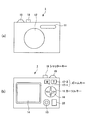
図1は、本実施形態に係る撮像装置(デジタルカメラ1)の外観構成を示すものであり、図1(a)はその正面図、図1(b)はその背面図を示している。撮像装置(デジタルカメラ1)は、図1に示すように、その正面側にストロボ発光部11と撮像レンズ(レンズ群)12とを備えている。
FIG. 1 shows an external configuration of an imaging apparatus (digital camera 1) according to the present embodiment. FIG. 1 (a) shows a front view thereof, and FIG. 1 (b) shows a rear view thereof. As shown in FIG. 1, the imaging apparatus (digital camera 1) includes a strobe
また、撮像装置(デジタルカメラ1)の背面には、図1(b)に示すように、モードダイヤル13と、液晶モニタ画面14と、カーソルキー15と、SETキー16と、望遠撮影時に用いられるズームキー(Wideボタン17−1、Teleボタン17−2)17と、撮影モード選択キー20等とが設けられている。
Further, as shown in FIG. 1B, on the back surface of the imaging device (digital camera 1), a
さらに、撮像装置(デジタルカメラ1)の上面には、図1(a)及び図1(b)に示すように、シャッターキー18と、電源ボタン19等とが設けられ、図示しない撮像装置(デジタルカメラ1)の側面には、パーソナルコンピュータやモデム等の外部装置をUSBケーブルで接続する場合に用いられるUSB(Universal Serial Bus)端子の接続部や、メモリカード等を挿入するスロット等が設けられている。
Further, as shown in FIGS. 1A and 1B, a
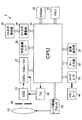
図2は、本実施形態に係る撮像装置(デジタルカメラ1)の内部の電気的構成を示すものである。
本実施形態に係る撮像装置は、図2に示すように、撮像レンズ22と、レンズ駆動ブロック23と、絞り兼用シャッター24と、CCD撮像素子21と、TG(Timing Generator)26と、ユニット回路(CDS/AGC/AD)27と、DRAM(Dynamic Random Access Memory)28と、メモリ29と、CPU(Central Processing unit)30と、画像表示部31と、キー入力部32と、外部通信I/F(Interface)33と、ストロボ駆動部34と、ストロボ発光部35と、カードI/F(Interface)36と、を備えており、カードI/F36には、図示しないデジタルカメラ1本体のカードスロットにメモリカード40が着脱可能に接続される。
FIG. 2 shows an internal electrical configuration of the imaging apparatus (digital camera 1) according to the present embodiment.
As shown in FIG. 2, the imaging apparatus according to the present embodiment includes an
撮像レンズ22は、フォーカスレンズ、ズームレンズを含み、レンズ駆動ブロック23が接続されている。このレンズ駆動ブロック23は、図示しないフォーカスレンズ、ズームレンズをそれぞれ撮像面と平行な光軸方向に駆動させるフォーカスモータ及びズームモータと、CPU30からの制御信号にしたがってフォーカスモータ及びズームモータをそれぞれ駆動させるフォーカスドライバ及びズームモータドライバから構成されている。
The
絞り兼用シャッター24は、図示しない駆動回路を含み、この駆動回路はCPU30から送られてくる制御信号にしたがって絞り兼用シャッターを動作させる。なお、この絞り兼用シャッター24は、絞りとシャッターとして機能する。
The aperture /
CCD撮像素子21は、撮像レンズ22及び絞り兼用シャッター24を介して投影された被写体の光を電気信号に変換し、撮像信号としてユニット回路(CDS/AGC/AD)27に出力する。また、CCD撮像素子21は、TG26によって生成された所定周波数のタイミング信号にしたがって駆動する。なお、TG26にはユニット回路(CDS/AGC/AD)27が接続されている。
The
ユニット回路(CDS/AGC/AD)27は、CCD撮像素子21から出力される撮像信号を相関二重サンプリングして保持するCDS(Correlated Double Sampling)回路、そのサンプリング後の撮像信号の自動利得調整を行うAGC(Automatic Gain Control)回路、その自動利得調整後のアナログの撮像信号をデジタル信号に変換するA/D変換器から構成されており、CCD撮像素子21の撮像信号は、ユニット回路(CDS/AGC/AD)27を経てデジタル信号としてCPU30に送られる。
The unit circuit (CDS / AGC / AD) 27 is a CDS (Correlated Double Sampling) circuit that holds the imaging signal output from the
CPU30は、ユニット回路(CDS/AGC/AD)27から送られてきた画像データの画像処理(画素補間処理、ガンマ補正、輝度色差信号の生成、ホワイトバランス処理、露出補正処理等)、振れ補正処理、画像データの圧縮・伸張(例えば、JPEG形式の圧縮・伸張)の処理等を行う機能を有するとともに、デジタルカメラ1の各部を制御プログラムにしたがって制御するワンチップマイコンである。
The
DRAM28は、CCD撮像素子21によって撮像された後、CPU30に送られてきた画像データを一時記憶するバッファメモリとして使用されるとともに、CPU30のワーキングメモリとしても使用される。
The
画像表示部31は、カラーLCD(Liquid Crystal Display)とその駆動回路とを含み、撮影待機状態にあるときには、CCD撮像素子21によって撮像された被写体をスルー画像として表示し、記録画像の再生時には、メモリカード40から読み出され、伸張された記録画像を表示させる。
The
キー入力部32は、モードダイヤル13、カーソルキー15、SETキー16、ズームキー17、シャッターキー18、電源ボタン19、撮影モード選択キー20(図1(a)及び図1(b)参照)等の複数の作キーを含み、ユーザのキー操作に応じた操作信号をCPU30に出力する。
The
外部通信I/F33は、外部の電子機器(例えば、パーソナルコンピュータ)との間でデータの入出力を行うものであり、USB規格、IEEE1394規格などの各種インターフェース規格による入出力を可能としており、これらの規格によるデータ入出力が可能なパソコンなどの電子機器と接続可能となっている。また、IrDA規格による赤外線通信、Bluetooth規格による無線通信により外部の電子機器と画像データの入出力を可能としているものでもよい。
The external communication I /
ストロボ駆動部34は、CPU30の制御信号にしたがって、ストロボ発光部35を閃光駆動させ、ストロボ発光部35は、これによりストロボを閃光させる。CPU30は、図示しない測光回路により、撮影シーンが暗いか否かを判断し、撮影シーンが暗いと判断し、かつ、撮影を行う場合(シャッターキーの押下時)には、ストロボ駆動部34に制御信号を出力する。
The
メモリ29は、CPU30によるデジタルカメラ1の各部の制御に必要なプログラム及び各部の制御に必要なデータを記録格納しており、CPU30は、このプログラムにしたがって処理を実行する。
The
上述の撮像装置(デジタルカメラ1)において、シャッターキー18(キー入力部32に含まれる)が操作されると、撮像レンズ22及び絞り兼用シャッター24を介して投影された被写体像光がCCD撮像素子21に取り込まれ、CCD撮像素子21でこの画像が電気信号に変換され、撮像信号としてユニット回路(CDS/AGC/AD)27に出力される。そして、CPU30により、ユニット回路(CDS/AGC/AD)27から送られてきた画像データに対して、画像処理が行われ、JPEG等により圧縮されて、メモリカード40に記録される。
When the shutter key 18 (included in the key input unit 32) is operated in the above-described imaging apparatus (digital camera 1), the subject image light projected through the
ここで、撮影者が撮像装置で撮影を行う際に、カメラが動いてしまったり、被写体が動いたりすると、手振れや画振れにより撮影画像にボケが生じてしまう。そこで、本実施形態では、手振れや画振れを検出し、手振れや画振れが収束したら、撮影記録が行えるようにしている。このように、手振れや画振れが収束してから、撮影記録が行えるようにするための動作について、以下に説明する。 Here, when the photographer takes a picture with the imaging apparatus, if the camera moves or the subject moves, the photographed image is blurred due to camera shake or image shake. Therefore, in the present embodiment, camera shake and image blur are detected, and when the camera shake and the image blur converge, shooting and recording can be performed. An operation for enabling shooting and recording after the hand shake and the image blur have converged will be described below.
図3は、本実施形態において、手振れや画振れを検出して、撮影記録のタイミングを制御するための機能を実現するための構成を示す機能ブロック図である。なお、この機能ブロック図は、CPU30を使ってソフトウェアにより実現することが可能である。
FIG. 3 is a functional block diagram showing a configuration for realizing a function for detecting camera shake or image blur and controlling the timing of shooting and recording in the present embodiment. This functional block diagram can be realized by software using the
図3に示すように、本実施形態においては、第1の画振れ検出部101と、第2の画振れ検出部102と、判断部103とが設けられている。第1の画振れ検出部101及び第2の画振れ検出部102は、共に画像データから画振れを検出するものであるが、検出速度や検出精度が異なっている。さらに、本実施形態では、画像フレーム内の高周波成分を検出する高周波検出部105が設けられている。なお、高周波検出部105の働きについては後に説明する。
As shown in FIG. 3, in the present embodiment, a first image
第1の画振れ検出部101は、撮影の初期段階で、大まかな画振れの発生の程度を検出するものである。つまり、撮影を行う際に、撮影者は、デジタルカメラ1を大きく動かして画角を決め、画角が決まったら、デジタルカメラ1を静止させるようにして、撮影を行う。したがって、撮影の初期段階では、大まかな画振れを検出し、デジタルカメラ1がある程度静止させた状態になったことを検出する必要がある。第1の画振れ検出部101は、このような撮影の初期段階の手振れを検出している。第1の画振れ検出部101としては、高い検出精度は要求されないが、大きな画振れを高速に検出できることが要求される。
The first image
これに対して、第2の画振れ検出部102は、ある程度手振れが収束した後に、細かい画振れを検出するものである。つまり、撮影者は、画角が決めた後に、デジタルカメラ1を静止させて、撮影を行う。しかしながら、ここで、デジタルカメラ1が僅かに動いてしまったり、被写体が動いてしまったりすることがある。第2の画振れ検出部102は、撮影者が画角を決めた後にデジタルカメラ1を静止させている間に、手振れや画振れの発生の程度を高い精度で検出するものである。第2の画振れ検出部102としては、大まかな手振れを検出できることは要求されないが、精度の高い検出が要求される。
On the other hand, the second image
判断部103は、最初に、第1の画振れ検出部101からの検出出力に基づいて、大まかな画振れの程度を判断し、ある程度、画振れが収束したと判断された後に、第2の画振れ検出部102からの検出出力により、より詳細に画振れの程度が判断し、画振れがないと判断されたら、手振れや画振れのないことを示す信号を撮影記録処理部104に送り、撮影記録を行うようにしている。
The
このように、本実施形態では、大まかな画振れを高速で検出できる第1の画振れ検出部101と、精度の高い画振れを検出できる第2の画振れ検出部102との2つの画振れ検出部が設けられており、最初に、第1の画振れ検出部101からの検出出力に基づいて、大まかな画振れの程度を判断し、ある程度、画振れが収束したと判断された後に、第2の画振れ検出部102からの検出出力により、より詳細に画振れの程度が判断し、画振れがないと判断されたら、記録撮影を行うようにしている。これにより、手振れや画振れのないタイミングで、確実に、撮影を行うことができる。
As described above, in the present embodiment, the two image shakes of the first image
なお、撮影記録処理部104は、判断部103から、手振れや画振れのないことを示す信号が送られてきたら、自動的に、記録撮影を行うように制御してもよい。また、判断部103から、手振れや画振れのないことを示す信号が送られてこなければ、撮影を禁止するように制御してもよい。また、判断部103から、手振れや画振れのないことを示す信号により撮影タイミングを判断し、撮影指示のときに、警告を発生させるようにしてもよい。
Note that the shooting /
次に、第1及び第2の画振れ検出部101及び102について説明する。
Next, the first and second image
第1の画振れ検出部101は、上述のように、大まかな画振れを検出して、デジタルカメラ1が静止された状態になったことを判断するものである。デジタルカメラ1が静止された状態は、画角全体の動きが小さくなった状態であり、これは、グローバル動きベクトルにより求めることができる。
As described above, the first image
つまり、画像フレームFn−1内のある1点に注目し、その点が次の画像フレームFnのどこに移動するかを求めれば、その点についての動きベクトルを求めることができる。しかしながら、被写体には背景部分と動いている部分とがあり、動いている部分の動きベクトルでは、全体の動きを判断できない。例えば、手振れ方向と逆方向に被写体が動いたような場合には、手振れが生じているにも係わらず、動きベクトルは非常に小さい値になってしまうことが考えられるからである。 That is, if a certain point in the image frame F n−1 is focused on and where the point moves in the next image frame F n , the motion vector for that point can be obtained. However, the subject has a background portion and a moving portion, and the overall motion cannot be determined from the motion vector of the moving portion. For example, when the subject moves in the direction opposite to the direction of camera shake, the motion vector may be a very small value despite the occurrence of camera shake.
そこで、本実施形態では、画像フレームからN個(Nは十分に大きい整数)の特徴点を抽出し、N個の動きベクトルを求め、サポート数を計算し、最もサポート数の大きい動きベクトルをグローバル動きベクトルとし、このグローバル動きベクトルが小さくなったら、デジタルカメラ1が静止された状態になったと判断するようにしている。
Therefore, in this embodiment, N (N is a sufficiently large integer) feature points are extracted from the image frame, N motion vectors are obtained, the number of supports is calculated, and the motion vector having the largest number of supports is globally determined. When the global motion vector becomes small, it is determined that the
ここで、サポート数は、1つの動きベクトルに対して、その動きベクトルと同様な動きベクトルの数がいくつあるかを示すものである。すなわち、ある1つの動きベクトルをMVaとし、残りの動きベクトルをMVi(iは0〜Nの整数)とし、Dを定数とすると、サポート数は、|MVa−MVi|<Dを満たす個数として計算できる。 Here, the number of supports indicates the number of motion vectors similar to the motion vector for one motion vector. That is, if one motion vector is MV a , the remaining motion vectors are MV i (i is an integer from 0 to N), and D is a constant, the number of supports is | MV a −MV i | <D. It can be calculated as the number of filling
背景の部分の動きベクトルは、全体の動きを反映しているので、同様な値となる動きベクトルが多くあり、サポート数が大きくなる。これに対して、動いている被写体の部分の動きベクトルは、全体の動きとは異なるので、サポート数が小さくなる。このことから、サポート数が大きい動きベクトルは、グローバル動きベクトルを示すことになる。 Since the motion vector of the background portion reflects the overall motion, there are many motion vectors having similar values, and the number of supports is large. On the other hand, since the motion vector of the moving subject portion is different from the overall motion, the number of supports is small. Therefore, a motion vector with a large number of supports indicates a global motion vector.
一方、第2の画振れ検出部102は、前述したように、ある程度手振れが収束した後に、細かい画振れを検出するものである。このような細かい画振れは、画像フレーム間の差分値により検出できる。
On the other hand, as described above, the second image
つまり、画像フレームFnのある座標をFn(x,y)とすると、画像フレーム間の差分値は、Σ|Fn(x,y)−Fn−1(x,y)|(Σは、全画素の累積値)として計算することができる。画振れが発生すると、この画像フレーム間の差分値が大きくなり、画振れがなくなれば、画像フレーム間の差分値は0に近い値になる。 That is, if a certain coordinate of the image frame F n is F n (x, y), the difference value between the image frames is Σ | F n (x, y) −F n−1 (x, y) | (Σ Can be calculated as a cumulative value of all pixels). When image blur occurs, the difference value between the image frames increases, and when there is no image blur, the difference value between image frames becomes a value close to zero.
そこで、本実施形態では、画像フレームFnと画像フレームFn−1との画像フレーム間の差分値を求め、画像フレーム間の差分値が小さくなったら、画振れがない状態であると判断するようにしている。 Therefore, in the present embodiment, the difference value between the image frames F n and F n−1 is obtained, and when the difference value between the image frames becomes small, it is determined that there is no image blur. I am doing so.
しかしながら、実際は、ランダムノイズの影響等により、画像フレーム間の差分値が0になることはない。また、画像フレーム間の差分値は、撮影環境や露光条件、ゲイン等により変化するので、閾値を一律に決定することはできない。そこで、本実施形態では、初期に判断された画像フレーム間の差分値が徐々に小さくなっていき、ある程度小さくなったら、画振れがないと判断するようにしている。 However, in reality, the difference value between image frames does not become zero due to the influence of random noise or the like. In addition, since the difference value between image frames varies depending on the shooting environment, exposure conditions, gain, and the like, the threshold cannot be determined uniformly. In view of this, in the present embodiment, the difference value between image frames determined in the initial stage is gradually reduced, and when it is reduced to some extent, it is determined that there is no image blur.
つまり、初期段階の最初の画像フレームで、画像フレーム間の差分値を求め、この画像フレーム間の差分値を基準値Aとして登録する。そして、それ以降の画像フレームで検出された画像フレーム間の差分値と基準値Aとを比較していく。ここで、以降の画像フレーム間の差分値が基準値Aよりも小さくなった場合、その画像フレームでは、基準値Aを求めたときの画像フレームよりも、画振れが小さくなったと判断できる。 That is, the difference value between the image frames is obtained at the first image frame in the initial stage, and the difference value between the image frames is registered as the reference value A. Then, the difference value between the image frames detected in the subsequent image frames is compared with the reference value A. Here, when the difference value between subsequent image frames becomes smaller than the reference value A, it can be determined that the image blur is smaller in the image frame than in the image frame when the reference value A is obtained.
この場合、そのとき求められた画像フレーム間の差分値で、基準値Aを更新し、同様の処理を複数回繰り返していく。これにより、画像フレーム間の差分値が徐々に小さくなり、ある程度小さくなったことが判断できる。そして、基準値Aの更新回数が所定以上になったら、画振れが少ない状態であると判断する。 In this case, the reference value A is updated with the difference value between the image frames obtained at that time, and the same processing is repeated a plurality of times. Thereby, it can be determined that the difference value between the image frames is gradually reduced to a certain extent. When the number of updates of the reference value A exceeds a predetermined value, it is determined that there is little image blur.
ところが、この条件だけでは、被写体振れの大きさを正しく評価できない場合がある。例えば、画像フレーム間で被写体が大きく動いてボケてしまった画像や、一様に真っ暗な画像などでは、画像フレーム間の差分値の信頼性は低い。 However, in some cases, the magnitude of subject shake cannot be evaluated correctly only with this condition. For example, the reliability of the difference value between image frames is low in an image in which the subject has moved greatly between image frames and the image is uniformly dark.
そこで、本実施形態では、画像フレーム内の高周波成分を検出する高周波検出部105が設けられている。すなわち、高周波検出部105により、画像フレーム内の高周波成分が検出され、高周波成分が基準値より小さい画像フレームは、画像フレーム間の差分値による画振れの評価の対象から外されるようになっている。
Therefore, in the present embodiment, a high
つまり、初期段階で最初の画像フレームから高周波成分を計算し、その値をもとに高周波成分の基準値Bを設定する。次回以降、画像フレーム内で高周波成分を求め、求められた高周波成分と基準値Bとを比較していく。そして、求められた高周波成分が基準値Bよりも小さい画像フレームでは、画面がボケているとして、画像フレーム間の差分値による画振れの評価の対象から外すようする。 That is, the high frequency component is calculated from the first image frame in the initial stage, and the reference value B of the high frequency component is set based on the value. From the next time, the high frequency component is obtained in the image frame, and the obtained high frequency component is compared with the reference value B. Then, in an image frame in which the obtained high-frequency component is smaller than the reference value B, it is assumed that the screen is blurred and is excluded from the image blur evaluation target based on the difference value between the image frames.
このように、第2の画振れ検出部102は、画像フレーム間の差分値と画像フレーム内の高周波成分との2つを用いて、画振れを判断している。つまり、前述したように更新されていく画像フレーム間の差分値の基準値をAとし、初期段階で設定される高周波成分の基準値をBとしたときに、以下の2つの条件を両方とも満足したかどうかを判断している。
As described above, the second image
条件(1):画像フレーム間の差分値が基準値Aより小さい。
条件(2):画像フレーム内の高周波成分が基準値Bより大きい。
Condition (1): The difference value between image frames is smaller than the reference value A.
Condition (2): The high frequency component in the image frame is larger than the reference value B.
図4は、上述の処理を行うためのフローチャートである。
図4において、撮像された1画像フレームの画像が出力され(ステップS1)、グローバル動きベクトル(GMV)の検出処理が行われる(ステップS2)。グローバル動きベクトル(GMV)の検出処理では、N個の特徴点を抽出し、N個の動きベクトルを求め、サポート数を計算し、最もサポート数の高い動きベクトルをグローバル動きベクトル(GMV)とする処理が行われる。なお、グローバル動きベクトル(GMV)の検出処理フローについては、後に説明する。
FIG. 4 is a flowchart for performing the above-described processing.
In FIG. 4, an image of one captured image frame is output (step S1), and a global motion vector (GMV) detection process is performed (step S2). In the global motion vector (GMV) detection process, N feature points are extracted, N motion vectors are obtained, the number of supports is calculated, and the motion vector with the highest support number is defined as the global motion vector (GMV). Processing is performed. The global motion vector (GMV) detection process flow will be described later.
グローバル動きベクトル(GMV)が検出されたら、このグローバル動きベクトル(GMV)を評価して、グローバル動きベクトル(GMV)が十分に小さいかどうかが判断される(ステップS3)。 When the global motion vector (GMV) is detected, the global motion vector (GMV) is evaluated to determine whether the global motion vector (GMV) is sufficiently small (step S3).
撮影者が画角を決めているような場合には、デジタルカメラ1が静止されていないため、グローバル動きベクトル(GMV)は大きな値となる。つまり、グローバル動きベクトル(GMV)が大きければ(ステップS3の「No」の場合)、次の画像フレームに処理が移され(ステップS4)、ステップS2にリターンされ、グローバル動きベクトル(GMV)の検出処理が続けられる。
When the photographer determines the angle of view, since the
撮影者が画角を決め、デジタルカメラ1を静止させると、グローバル動きベクトル(GMV)は小さな値となる。つまり、ステップS3で、グローバル動きベクトル(GMV)が十分に小さければ(ステップS3の「Yes」の場合)、画像フレーム間の差分値が求められ、この画像フレーム間の差分値が基準値Aとされる(ステップS5)。画像フレーム間の差分値は、前述したように、Σ|Fn(x,y)−Fn−1(x,y)|として計算される。そして、画像フレーム内の高周波成分が求められ、この画像フレーム内の高周波成分が基準値Bとされる(ステップS6)。
When the photographer determines the angle of view and stops the
次の画像フレームの画像が出力され(ステップS7)、その画像フレームで、画像フレーム間の差分値が求められ(ステップS8)、画像フレーム内の高周波成分が求められる(ステップS9)。そして、画像フレーム間の差分値が基準値Aよりも小さく、かつ、画像フレーム内の高周波成分が基準値Bより大きいかどうかが判断される(ステップS10)。 An image of the next image frame is output (step S7), and a difference value between the image frames is obtained in the image frame (step S8), and a high frequency component in the image frame is obtained (step S9). Then, it is determined whether or not the difference value between the image frames is smaller than the reference value A and the high frequency component in the image frame is larger than the reference value B (step S10).
画像フレーム間の差分値が基準値Aより大きい、又は、画像フレーム内の高周波成分が基準値Bより小さい場合(ステップS10の「No」の場合)には、画像フレーム間の差分値が許容値より大きいかどうかが判断され(ステップS11)、画像フレーム間の差分値が許容値より大きくなければ(ステップS11の「No」の場合)、ステップS7にリターンされる。 When the difference value between the image frames is larger than the reference value A or the high frequency component in the image frame is smaller than the reference value B (in the case of “No” in step S10), the difference value between the image frames is an allowable value. It is determined whether or not the difference is larger (step S11), and if the difference value between the image frames is not larger than the allowable value (in the case of “No” in step S11), the process returns to step S7.
手振れが収まらない場合や被写体の画振れが生じているような場合には、画像フレーム間の差分値が基準値Aより大きくなる。また、画面がボケてきた場合には、画像フレーム内の高周波成分が基準値Bより小さくなる。よって、これらの場合には、ステップS10の判断結果が「No」となり、ステップS7〜ステップS11の処理が繰り返し実行される。 When the camera shake does not fall out or when the subject shakes, the difference value between the image frames becomes larger than the reference value A. When the screen is blurred, the high frequency component in the image frame becomes smaller than the reference value B. Therefore, in these cases, the determination result in step S10 is “No”, and the processes in steps S7 to S11 are repeatedly executed.
また、撮影者が一度決めた画角を外して、デジタルカメラ1を大きく動かすような場合がある。この場合には、ステップS11で、画像フレーム間の差分値が許容値より大きいと判断されることになる。したがって、このような場合(ステップS11の「Yes」の場合)には、ステップS4で、次の画像フレームに処理が移され、ステップS2リターンされる。
Further, there are cases where the angle of view once determined by the photographer is removed and the
手振れや画振れが生じていない場合には、画像フレーム間の差分値が基準値Aより小さくなる。また、画面がボケていなければ、画像フレーム内の高周波成分が基準値Bより大きくなる。よって、これらの場合には、ステップS10の判断結果が「Yes」となる。 When there is no camera shake or image blur, the difference value between image frames is smaller than the reference value A. If the screen is not blurred, the high frequency component in the image frame is larger than the reference value B. Therefore, in these cases, the determination result in step S10 is “Yes”.
ステップS10で、画像フレーム間の差分値が基準値Aより小さく、かつ、画像フレーム内の高周波成分が基準値Bより大きい場合(ステップS10の「Yes」の場合)には、基準値Aが今回の画像フレーム間の差分値で更新される(ステップS12)。そして、更新回数が所定回数に達したかどうかが判断され(ステップS13)、更新回数が所定回数に達していなければ(ステップS13の「No」の場合)、ステップS7にリターンされる。 In step S10, if the difference value between the image frames is smaller than the reference value A and the high frequency component in the image frame is larger than the reference value B (in the case of “Yes” in step S10), the reference value A is the current value. It is updated with the difference value between the image frames (step S12). Then, it is determined whether or not the number of updates has reached a predetermined number (step S13). If the number of updates has not reached the predetermined number (in the case of “No” in step S13), the process returns to step S7.
このように、最初の画像フレーム間の差分値を基準値Aとし、以降の画像フレーム間の差分値と基準値Aとを比較していき、以降の画像フレーム間の差分値が基準値Aよりも小さくなった場合、そのとき求められた画像フレーム間の差分値で、基準値Aを更新し、それ以降、同様の処理を複数回繰り返していくことで、画像フレーム間の差分値が徐々に小さくなることを検出していくことができる。 In this way, the difference value between the first image frames is set as the reference value A, the difference value between the subsequent image frames is compared with the reference value A, and the difference value between the subsequent image frames is compared with the reference value A. Is also reduced, the reference value A is updated with the difference value between the image frames obtained at that time, and thereafter, the same process is repeated a plurality of times so that the difference value between the image frames gradually increases. It is possible to detect the decrease.
ステップS13で、更新回数が所定回数に達した場合(ステップS13の「Yes」の場合)には、手振れや画振れがないと判断される(ステップS14)。 If the number of updates reaches a predetermined number in step S13 (in the case of “Yes” in step S13), it is determined that there is no camera shake or image blur (step S14).
図5は、図4におけるステップS2のグローバル動きベクトルの検出処理を示すフローチャートである。 FIG. 5 is a flowchart showing the global motion vector detection process of step S2 in FIG.
図5において、画像フレームFn−1からN個の特徴点が抽出され(ステップS101)、それに連続する画像フレームFnとを比較して、各特徴点がどこに移動したかが追跡される(ステップS102)。これにより、動きベクトルが求められる(ステップS103)。 In FIG. 5, N feature points are extracted from the image frame F n−1 (step S101), and the image frames F n continuous with the feature points are extracted to track where each feature point has moved ( Step S102). Thereby, a motion vector is calculated | required (step S103).
N回の処理が繰り返されたかどうかが判断され(ステップS104)、N回繰り返していなければ(ステップS104のNoの場合)、次の位置の特徴点に処理が移されて(ステップS105)、ステップS101にリターンされ、同様の処理が繰り返される。これにより、N個各点の動きベクトルが求められる。N個の全てのブロックについて動きベクトルが求められると、ステップS104で、N回の処理が繰り返されたと判断される。 It is determined whether or not the process has been repeated N times (step S104). If the process has not been repeated N times (No in step S104), the process moves to the next feature point (step S105). Returning to S101, the same processing is repeated. Thereby, a motion vector of each of N points is obtained. When motion vectors have been obtained for all N blocks, it is determined in step S104 that N processes have been repeated.
ステップS104で、N回の処理が繰り返されたと判断された場合(ステップS104の「Yes」の場合)、サポート数の基準値Cが初期値(例えば0)に設定される(ステップS106)。そして、1つの動きベクトルについてのサポート数が計算される(ステップS107)。ここで、前述したように、サポート数は、|MVa−MVi|<Dを満たす個数として計算できる。 If it is determined in step S104 that the process has been repeated N times (in the case of “Yes” in step S104), the reference number C of the support number is set to an initial value (for example, 0) (step S106). Then, the number of supports for one motion vector is calculated (step S107). Here, as described above, the number of supports can be calculated as a number satisfying | MV a −MV i | <D.
サポート数が求められたら、求められたサポート数がサポート数の基準値Cより大きいかどうかが判断される(ステップS108)。 When the support number is obtained, it is determined whether or not the obtained support number is larger than the support number reference value C (step S108).
ステップS108で、今回求められたサポート数が基準値Cより大きければ(ステップS108で「Yes」の場合)、サポート数の基準値Cが今回のサポート数により更新され(ステップS109)、N回の処理が繰り返されたかどうかが判断される(ステップS110)。ステップS108で、サポート数が基準値Cより小さければ(ステップS108で「No」の場合)、サポート数の基準値Cはそのままで、N回の処理が繰り返されたかどうかが判断される(ステップS110)。 If the support number obtained this time is larger than the reference value C in step S108 (in the case of “Yes” in step S108), the support value reference value C is updated with the current support number (step S109). It is determined whether the process has been repeated (step S110). If the number of supports is smaller than the reference value C in step S108 (in the case of “No” in step S108), it is determined whether the support number reference value C is left as it is and N processes are repeated (step S110). ).
ステップS110で、N回の処理が繰り返されていなければ(ステップS110で「No」の場合)、次の位置の動きベクトルに処理が移され(ステップS111)、ステップS107にリターンされ、同様の処理が繰り返される。これらの処理が繰り返されることで、サポート数の基準値Cがそれまでのサポート数の最大値に更新されていく。 If the process is not repeated N times in step S110 (in the case of “No” in step S110), the process is moved to the motion vector at the next position (step S111), the process is returned to step S107, and the same process is performed. Is repeated. By repeating these processes, the reference number C of the support number is updated to the maximum value of the support number so far.
ステップS110で、N回の処理が繰り返されたと判断されたら(ステップS110で「Yes」の場合)、サポート数の基準値Cから、それまでのサポート数の最大値が判断され、サポート数が最大となる動きベクトルから、グローバル動きベクトル(GMV)が求められる(ステップS112)。 If it is determined in step S110 that the process has been repeated N times (in the case of “Yes” in step S110), the maximum value of the number of supports up to that time is determined from the reference value C of the number of supports, and the number of supports is maximum. A global motion vector (GMV) is obtained from the motion vector to be (step S112).
以上説明したように、本実施形態では、最初に、グローバル動きベクトルを用いて大まかな画振れの程度を判断し、ある程度、画振れが収束したと判断された後に、画像フレーム間の差分値を用いて、より詳細に画振れの程度が判断し、画振れがないと判断されたら、記録撮影を行うようにしている。これにより、手振れや画振れのないタイミングで、確実に、撮影を行うことができる。 As described above, in the present embodiment, first, the degree of rough image blur is determined using the global motion vector, and after determining that the image blur has converged to some extent, the difference value between image frames is calculated. In this way, the degree of image blur is determined in more detail, and when it is determined that there is no image blur, recording is performed. Thereby, it is possible to reliably perform shooting at a timing without camera shake or image blur.
なお、本実施形態では、動きベクトルの検出を行っているが、MPEGなどの動画のリアルタイム圧縮記録手段を備えたデジタルカメラなどにおいては、動画圧縮の際に動きベクトルを検出しているので、この動画圧縮の際に検出された動きベクトルを用いて画振れの検出を行うようにしてもよく、この場合には、専用の動きベクトル検出処理を実行する必要がなくなるので、処理効率や処理速度を向上させることができる。 In the present embodiment, the motion vector is detected. However, in a digital camera or the like equipped with a real-time compression recording unit for moving images such as MPEG, the motion vector is detected at the time of moving image compression. Image blur may be detected using a motion vector detected at the time of video compression. In this case, it is not necessary to execute a dedicated motion vector detection process. Can be improved.
また、本実施形態では、画像の高周波成分を検出しているが、オートフォーカス(AF)機能を備えたデジタルカメラなどにおいては、オートフォーカス処理の際に検出されるコントラスト情報を利用して高周波成分を検出するようにしてもよい。また、オートフォーカスの動作中に第1の画振れ検出部による画振れ検出を行い、オートフォーカスの動作が完了した後に第2の画振れ検出部による画振れ検出を行うようにしてもよい。 In this embodiment, the high-frequency component of the image is detected. However, in a digital camera or the like having an autofocus (AF) function, the high-frequency component is used by using contrast information detected during autofocus processing. May be detected. Alternatively, image blur detection by the first image blur detection unit may be performed during the autofocus operation, and image blur detection by the second image blur detection unit may be performed after the autofocus operation is completed.
また、自動露出(AE)機能を備えたデジタルカメラなどにおいては、自動露出の動作中に第1の画振れ検出部による画振れ検出を行い、自動露出の動作が完了した後に第2の画振れ検出部による画振れ検出を行うようにしてもよい。 In a digital camera or the like having an automatic exposure (AE) function, image blur detection is performed by the first image blur detection unit during the automatic exposure operation, and the second image blur is detected after the automatic exposure operation is completed. Image blur detection by the detection unit may be performed.
また、ソースとなるプログラムは、フレキシブルディスク、光磁気ディスク、ROM、CD−ROM等の可搬媒体等のコンピュータ読み取り可能な記録媒体で提供される。また、ソースとなるプログラムは、コンピュータシステムから、伝送媒体を介して、あるいは、伝送媒体中の伝送波により他のコンピュータシステムに伝送されてもよい。ここで、プログラムを伝送する「伝送媒体」は、インターネット等のネットワーク(通信網)や電話回線等の通信回線(通信線)のように情報を伝送する機能を有する媒体のことをいう。また、ソースとなるプログラムは、前述した機能の一部を実現するためのものであっても良い。さらに、前述した機能をコンピュータシステムにすでに記録されているプログラムとの組み合わせで実現できるもの、いわゆる差分ファイル(差分プログラム)であっても良い。 The source program is provided by a computer-readable recording medium such as a portable medium such as a flexible disk, a magneto-optical disk, a ROM, or a CD-ROM. The source program may be transmitted from a computer system to another computer system via a transmission medium or by a transmission wave in the transmission medium. Here, the “transmission medium” for transmitting the program refers to a medium having a function of transmitting information, such as a network (communication network) such as the Internet or a communication line (communication line) such as a telephone line. The source program may be a program for realizing a part of the functions described above. Furthermore, what can implement | achieve the function mentioned above in combination with the program already recorded on the computer system, and what is called a difference file (difference program) may be sufficient.
また、本実施形態における構成要素は適宜、既存の構成要素等との置き換えが可能であり、また、他の既存の構成要素との組み合わせを含む様々なバリエーションが可能である。したがって、本実施形態の記載をもって、特許請求の範囲に記載された発明の内容を限定するものではない。 In addition, the constituent elements in the present embodiment can be appropriately replaced with existing constituent elements, and various variations including combinations with other existing constituent elements are possible. Therefore, the description of the present embodiment does not limit the contents of the invention described in the claims.
1・・・デジタルカメラ、11・・・ストロボ発光部、13・・・モードダイヤル、14・・・液晶モニタ画面、15・・・カーソルキー、16・・・SETキー、17・・・ズームキー、18・・・シャッターキー、19・・・電源ボタン、20・・・撮影モード選択キー、21・・・CCD撮像素子、22・・・撮像レンズ、23・・・レンズ駆動ブロック、24・・・絞り兼用シャッター、27・・・ユニット回路(CDS/AGC/AD)、28・・・DRAM、29・・・メモリ、30・・・CPU、31・・・画像表示部、32・・・キー入力部、33・・・外部通信I/F、34・・・ストロボ駆動部、35・・・ストロボ発光部、36・・・カードI/F、40・・・メモリカード、101・・・第1の画振れ検出部、102・・・第2の画振れ検出部、103・・・判断部、104・・・撮影記録処理部
DESCRIPTION OF
Claims (9)
連続して得られる複数の画像フレームより検出される画像全体の動きベクトルの大小により画振れを検出することで、手振れに起因する画振れ成分と被写体の動きに起因する画振れ成分のうち、手振れに起因する画振れ成分を検出する第1の画振れ検出手段と、
前記第1の画振れ検出手段により検出される画振れが収束したと判断された後に開始される画振れ検出処理であって、連続する2つの画像フレームの画像データを画素毎に比較した差分値の大小により画振れを検出することで、被写体にフォーカスが合っていない状態では画振れ検出の精度が低下するが、前記第1の画振れ検出手段より画振れ検出の精度が高く、かつ、手振れに起因する画振れ成分と被写体の動きに起因する画振れ成分とを区別せずに画振れを検出する第2の画振れ検出手段と、
前記第1の画振れ検出手段により検出される画振れが収束したと判断された後、更に、前記第2の画振れ検出手段により検出される画振れが収束したと判断された場合に、画振れが無くなったと判断する判断手段と、
前記判断手段により画振れが無くなったと判断された場合、自動的に撮影記録を行う撮影制御手段と、
を備えることを特徴とする。 An imaging device having an image blur detection function,
By detecting the image shake based on the magnitude of the motion vector of the entire image detected from a plurality of image frames obtained in succession, the image shake component among the image shake component caused by the camera shake and the image shake component caused by the motion of the subject is detected. First image blur detection means for detecting an image blur component caused by
The image blur detection process started after it is determined that the image blur detected by the first image blur detection unit has converged, and is a difference value obtained by comparing image data of two consecutive image frames for each pixel. By detecting the image blur based on the size of the image, the accuracy of the image blur detection is lowered when the subject is not in focus. However, the accuracy of the image blur detection is higher than that of the first image blur detection means, and the camera shake is low. Second image blur detection means for detecting image blur without distinguishing between the image blur component caused by the image blur and the image blur component caused by the movement of the subject ;
After it is determined that the image blur detected by the first image blur detection unit has converged, and further when the image blur detected by the second image blur detection unit is determined to have converged, the image blur is detected. A judging means for judging that the shake has been lost;
When it is determined by the determination means that there is no image blur, shooting control means for automatically shooting and recording,
It is characterized by providing.
前記判断手段は、前記高周波成分検出手段により検出される高周波成分が基準値よりも低下しているか否かを判断し、高周波成分が基準値より低下していると判断された画像フレームは評価対象から除いて、前記第2の画振れ検出手段により検出される差分値により画振れの有無を判断することを特徴とする請求項1に記載の撮像装置。 Furthermore, a high frequency component detection means for detecting a high frequency component in the image frame is provided,
The determination means determines whether or not the high-frequency component detected by the high-frequency component detection means is lower than a reference value, and the image frame determined that the high-frequency component is lower than the reference value is an evaluation target 2. The imaging apparatus according to claim 1 , wherein the presence or absence of image blur is determined based on a difference value detected by the second image blur detection unit.
前記判断手段は、前記高周波成分検出手段により検出される高周波成分が基準値よりも低下している画像フレームに基づいて検出された差分値は、保持されている差分値よりも小さい場合でも更新しないことを特徴とする請求項4に記載の撮像装置。 Furthermore, a high frequency component detection means for detecting a high frequency component in the image frame is provided,
The determination unit does not update the difference value detected based on the image frame in which the high-frequency component detected by the high-frequency component detection unit is lower than a reference value even when the difference value is smaller than the held difference value. The imaging apparatus according to claim 4 .
連続して得られる複数の画像フレームより検出される画像全体の動きベクトルの大小により画振れを検出することで、手振れに起因する画振れ成分と被写体の動きに起因する画振れ成分のうち、手振れに起因する画振れ成分を検出する第1の画振れ検出ステップと、
前記第1の画振れ検出ステップにより検出される画振れが収束したと判断された後に開始される画振れ検出処理であって、連続する2つの画像フレームの画像データを画素毎に比較した差分値の大小により画振れを検出することで、被写体にフォーカスが合っていない状態では画振れ検出の精度が低下するが、前記第1の画振れ検出手段より画振れ検出の精度が高く、かつ、手振れに起因する画振れ成分と被写体の動きに起因する画振れ成分とを区別せずに画振れを検出する第2の画振れ検出ステップと、
前記第1の画振れ検出ステップにより検出される画振れが収束したと判断された後、更に、前記第2の画振れ検出ステップにより検出される画振れが収束したと判断された場合に、画振れが無くなったと判断する判断ステップと、
前記判断ステップにより画振れが無くなったと判断された場合、自動的に撮影記録を行う撮影制御ステップと、
からなることを特徴とする撮像方法。 A method for controlling an image pickup apparatus having an image blur detection function,
By detecting the image shake based on the magnitude of the motion vector of the entire image detected from a plurality of image frames obtained in succession, the image shake component among the image shake component caused by the camera shake and the image shake component caused by the motion of the subject is detected. A first image blur detection step for detecting an image blur component caused by
In the image blur detection process started after it is determined that the image blur detected in the first image blur detection step has converged, the difference value obtained by comparing the image data of two consecutive image frames for each pixel By detecting the image blur based on the size of the image, the accuracy of the image blur detection is lowered when the subject is not in focus. However, the accuracy of the image blur detection is higher than that of the first image blur detection means, and the camera shake is low. A second image blur detection step for detecting image blur without distinguishing between the image blur component caused by the image blur and the image blur component caused by the movement of the subject ;
After it is determined that the image blur detected by the first image blur detection step has converged, and further when it is determined that the image blur detected by the second image blur detection step has converged, the image blur is detected. A judgment step for judging that the shake has been lost;
When it is determined that there is no image blur in the determination step, a shooting control step for automatically shooting and recording,
An imaging method comprising:
前記撮像装置のコンピュータを、
連続して得られる複数の画像フレームより検出される画像全体の動きベクトルの大小により画振れを検出することで、手振れに起因する画振れ成分と被写体の動きに起因する画振れ成分のうち、手振れに起因する画振れ成分を検出する第1の画振れ検出手段と、
前記第1の画振れ検出手段により検出される画振れが収束したと判断された後に開始される画振れ検出処理であって、連続する2つの画像フレームの画像データを画素毎に比較した差分値の大小により画振れを検出することで、被写体にフォーカスが合っていない状態では画振れ検出の精度が低下するが、前記第1の画振れ検出手段より画振れ検出の精度が高く、かつ、手振れに起因する画振れ成分と被写体の動きに起因する画振れ成分とを区別せずに画振れを検出する第2の画振れ検出手段と、
前記第1の画振れ検出手段により検出される画振れが収束したと判断された後、更に、前記第2の画振れ検出手段により検出される画振れが収束したと判断された場合に、画振れが無くなったと判断する判断手段と、
前記判断手段により画振れが無くなったと判断された場合、自動的に撮影記録を行う撮影制御手段と
して機能させることを特徴とする撮像プログラム。 A control program for an imaging apparatus having an image blur detection function,
A computer of the imaging device;
By detecting the image shake based on the magnitude of the motion vector of the entire image detected from a plurality of image frames obtained in succession, the image shake component among the image shake component caused by the camera shake and the image shake component caused by the motion of the subject is detected. First image blur detection means for detecting an image blur component caused by
The image blur detection process started after it is determined that the image blur detected by the first image blur detection unit has converged, and is a difference value obtained by comparing image data of two consecutive image frames for each pixel. By detecting the image blur based on the size of the image, the accuracy of the image blur detection is lowered when the subject is not in focus. However, the accuracy of the image blur detection is higher than that of the first image blur detection means, and the camera shake is low. Second image blur detection means for detecting image blur without distinguishing between the image blur component caused by the image blur and the image blur component caused by the movement of the subject ;
After it is determined that the image blur detected by the first image blur detection unit has converged, and further when the image blur detected by the second image blur detection unit is determined to have converged, the image blur is detected. A judging means for judging that the shake has been lost;
If it is determined that image blur has disappeared by the determination means, the image pickup program for causing to function as an imaging control means for automatically captured and recorded.
Priority Applications (7)
| Application Number | Priority Date | Filing Date | Title |
|---|---|---|---|
| JP2007132989A JP4872797B2 (en) | 2007-05-18 | 2007-05-18 | Imaging apparatus, imaging method, and imaging program |
| US12/151,446 US8564674B2 (en) | 2007-05-18 | 2008-05-07 | Image pickup apparatus equipped with function of detecting image shaking |
| CN2008100995936A CN101309357B (en) | 2007-05-18 | 2008-05-15 | Image pickup apparatus equipped with function of detecting image shaking |
| CN2009102252580A CN101742106B (en) | 2007-05-18 | 2008-05-15 | Image pickup apparatus equipped with function of detecting image shaking |
| KR1020080045595A KR100925319B1 (en) | 2007-05-18 | 2008-05-16 | Image pickup apparatus equipped with function of detecting image shaking, control method of the image pickup apparatus, and recording medium recording control program of the image pickup apparatus |
| EP08290459A EP1998558B1 (en) | 2007-05-18 | 2008-05-16 | Image pickup apparatus equipped with function of detecting image shaking |
| TW097117935A TWI386040B (en) | 2007-05-18 | 2008-05-16 | Image pickup apparatus equipped with function of detecting image shaking |
Applications Claiming Priority (1)
| Application Number | Priority Date | Filing Date | Title |
|---|---|---|---|
| JP2007132989A JP4872797B2 (en) | 2007-05-18 | 2007-05-18 | Imaging apparatus, imaging method, and imaging program |
Related Child Applications (1)
| Application Number | Title | Priority Date | Filing Date |
|---|---|---|---|
| JP2011098987A Division JP5182395B2 (en) | 2011-04-27 | 2011-04-27 | Imaging apparatus, imaging method, and imaging program |
Publications (3)
| Publication Number | Publication Date |
|---|---|
| JP2008288975A JP2008288975A (en) | 2008-11-27 |
| JP2008288975A5 JP2008288975A5 (en) | 2009-11-12 |
| JP4872797B2 true JP4872797B2 (en) | 2012-02-08 |
Family
ID=39831759
Family Applications (1)
| Application Number | Title | Priority Date | Filing Date |
|---|---|---|---|
| JP2007132989A Expired - Fee Related JP4872797B2 (en) | 2007-05-18 | 2007-05-18 | Imaging apparatus, imaging method, and imaging program |
Country Status (6)
| Country | Link |
|---|---|
| US (1) | US8564674B2 (en) |
| EP (1) | EP1998558B1 (en) |
| JP (1) | JP4872797B2 (en) |
| KR (1) | KR100925319B1 (en) |
| CN (2) | CN101309357B (en) |
| TW (1) | TWI386040B (en) |
Families Citing this family (22)
| Publication number | Priority date | Publication date | Assignee | Title |
|---|---|---|---|---|
| KR101494388B1 (en) | 2008-10-08 | 2015-03-03 | 삼성전자주식회사 | Apparatus and method for providing emotion expression service in mobile communication terminal |
| JP5570769B2 (en) | 2009-07-23 | 2014-08-13 | オリンパス株式会社 | Endoscope apparatus, measurement method, and program |
| KR101594297B1 (en) * | 2009-08-24 | 2016-02-16 | 삼성전자주식회사 | Method and apparatus for determining shaken image using auto focusing |
| KR101078754B1 (en) | 2010-05-24 | 2011-11-01 | 주식회사 인스프리트 | Mobile terminal having automatic function for camera image acquisition, and automatic method for camera image acqusition of mobile terminal using the same |
| CN102509285A (en) * | 2011-09-28 | 2012-06-20 | 宇龙计算机通信科技(深圳)有限公司 | Processing method and system for shot fuzzy picture and shooting equipment |
| KR101890305B1 (en) * | 2012-08-27 | 2018-08-21 | 삼성전자주식회사 | Photographing apparatus, method for controlling the same, and computer-readable recording medium |
| JP6019006B2 (en) * | 2013-11-07 | 2016-11-02 | 京セラドキュメントソリューションズ株式会社 | Image reading apparatus, image forming apparatus, and image reading method |
| CN104349039B (en) * | 2013-07-31 | 2017-10-24 | 展讯通信(上海)有限公司 | Video anti-fluttering method and device |
| CN105763786B (en) * | 2014-12-15 | 2019-07-26 | 联想(北京)有限公司 | A kind of information processing method and electronic equipment |
| CN106982320B (en) * | 2016-01-15 | 2019-07-23 | 珠海格力电器股份有限公司 | The control method and device of camera |
| CN105872376B (en) * | 2016-04-12 | 2017-10-17 | 广东欧珀移动通信有限公司 | Control method, control device and electronic installation |
| CN106060403A (en) * | 2016-07-05 | 2016-10-26 | 董超超 | Image pick-up device with image stabilization detection function |
| US10834318B2 (en) * | 2016-09-14 | 2020-11-10 | Huawei Technologies Co., Ltd. | Automatic photographing method and terminal based on use posture |
| CN108476286B (en) * | 2016-10-17 | 2020-09-08 | 华为技术有限公司 | Image output method and electronic equipment |
| CN106577350B (en) * | 2016-11-22 | 2020-10-09 | 深圳市沃特沃德股份有限公司 | Pet type identification method and device |
| CN107040693A (en) * | 2017-03-31 | 2017-08-11 | 西安万像电子科技有限公司 | Picture data processing method and processing device |
| CN108197621A (en) * | 2017-12-28 | 2018-06-22 | 北京金堤科技有限公司 | Company information acquisition methods and system and information processing method and system |
| CN113132617B (en) * | 2019-12-31 | 2023-04-07 | 北京中安未来科技有限公司 | Image jitter judgment method and device and image identification triggering method and device |
| CN114513609A (en) * | 2020-11-17 | 2022-05-17 | 浙江大华技术股份有限公司 | Camera exposure time adjusting method, image stroboscopic detection method and device |
| CN113438409B (en) * | 2021-05-18 | 2022-12-20 | 影石创新科技股份有限公司 | Delay calibration method, delay calibration device, computer equipment and storage medium |
| CN114125266B (en) * | 2021-10-20 | 2024-04-09 | 武汉旷视金智科技有限公司 | Rotation detection method, rotation detection device, rotation detection apparatus, rotation detection device, rotation detection medium, and rotation detection program product |
| CN116709023B (en) * | 2022-12-14 | 2024-03-26 | 荣耀终端有限公司 | Video processing method and device |
Family Cites Families (22)
| Publication number | Priority date | Publication date | Assignee | Title |
|---|---|---|---|---|
| US5012270A (en) * | 1988-03-10 | 1991-04-30 | Canon Kabushiki Kaisha | Image shake detecting device |
| JPH06350895A (en) | 1993-06-10 | 1994-12-22 | Fujitsu General Ltd | Method for correcting jiggle in video camera |
| KR100319034B1 (en) | 1993-06-29 | 2002-03-21 | 다카노 야스아키 | Video camera with image stabilization |
| JP3951321B2 (en) * | 1995-08-30 | 2007-08-01 | ソニー株式会社 | Image signal processing apparatus and recording / reproducing apparatus |
| JPH11317904A (en) | 1998-05-01 | 1999-11-16 | Canon Inc | Image pickup device and its control method |
| JP2000023023A (en) * | 1998-07-07 | 2000-01-21 | Canon Inc | Image pickup device and computer readable storage medium |
| US6487369B1 (en) * | 1999-04-26 | 2002-11-26 | Olympus Optical Co., Ltd. | Camera with blur reducing function |
| JP3770271B2 (en) * | 2002-12-26 | 2006-04-26 | 三菱電機株式会社 | Image processing device |
| JP2004354420A (en) | 2003-05-27 | 2004-12-16 | Fuji Photo Film Co Ltd | Automatic photographing system |
| KR100574523B1 (en) * | 2003-07-31 | 2006-04-27 | 삼성전자주식회사 | Apparatus and method for decision of motion type |
| JP3838243B2 (en) | 2003-09-04 | 2006-10-25 | ソニー株式会社 | Image processing method, image processing apparatus, and computer program |
| KR20060006427A (en) * | 2004-07-16 | 2006-01-19 | 삼성전자주식회사 | Photographing apparatus having auto focus control function and control method thereof |
| JP4315341B2 (en) | 2004-08-03 | 2009-08-19 | 富士フイルム株式会社 | Panning method and photographing apparatus |
| JP2006119199A (en) | 2004-10-19 | 2006-05-11 | Canon Inc | Optical equipment |
| JP4999268B2 (en) * | 2004-12-16 | 2012-08-15 | カシオ計算機株式会社 | Electronic camera and program |
| JP4639869B2 (en) | 2005-03-14 | 2011-02-23 | オムロン株式会社 | Imaging apparatus and timer photographing method |
| KR101144872B1 (en) | 2005-03-15 | 2012-05-14 | 삼성전자주식회사 | Apparatus and method for prdicting the smallest point of time of tremble in digital camera |
| JP2006311059A (en) * | 2005-04-27 | 2006-11-09 | Olympus Imaging Corp | Motion vector detection circuit and detection method thereof, and camera-shake correction apparatus |
| KR100674743B1 (en) | 2005-06-24 | 2007-01-25 | 미쓰비시덴키 가부시키가이샤 | Image processor |
| JP2007132989A (en) | 2005-11-08 | 2007-05-31 | Konica Minolta Opto Inc | Lens barrel and imaging apparatus |
| US7693406B2 (en) * | 2005-12-28 | 2010-04-06 | Seiko Epson Corporation | Image capturing apparatus, method of controlling the same, and storage medium |
| US7623683B2 (en) * | 2006-04-13 | 2009-11-24 | Hewlett-Packard Development Company, L.P. | Combining multiple exposure images to increase dynamic range |
-
2007
- 2007-05-18 JP JP2007132989A patent/JP4872797B2/en not_active Expired - Fee Related
-
2008
- 2008-05-07 US US12/151,446 patent/US8564674B2/en active Active
- 2008-05-15 CN CN2008100995936A patent/CN101309357B/en active Active
- 2008-05-15 CN CN2009102252580A patent/CN101742106B/en active Active
- 2008-05-16 EP EP08290459A patent/EP1998558B1/en active Active
- 2008-05-16 KR KR1020080045595A patent/KR100925319B1/en active IP Right Grant
- 2008-05-16 TW TW097117935A patent/TWI386040B/en not_active IP Right Cessation
Also Published As
| Publication number | Publication date |
|---|---|
| CN101742106B (en) | 2012-10-24 |
| KR100925319B1 (en) | 2009-11-04 |
| CN101309357B (en) | 2010-06-16 |
| CN101309357A (en) | 2008-11-19 |
| JP2008288975A (en) | 2008-11-27 |
| TW200906178A (en) | 2009-02-01 |
| EP1998558A2 (en) | 2008-12-03 |
| KR20080101778A (en) | 2008-11-21 |
| US8564674B2 (en) | 2013-10-22 |
| EP1998558B1 (en) | 2011-11-02 |
| TWI386040B (en) | 2013-02-11 |
| CN101742106A (en) | 2010-06-16 |
| US20080284858A1 (en) | 2008-11-20 |
| EP1998558A3 (en) | 2010-08-25 |
Similar Documents
| Publication | Publication Date | Title |
|---|---|---|
| JP4872797B2 (en) | Imaging apparatus, imaging method, and imaging program | |
| JP4999268B2 (en) | Electronic camera and program | |
| US10027909B2 (en) | Imaging device, imaging method, and image processing device | |
| JP4916513B2 (en) | Imaging device | |
| JP2008009263A (en) | Imaging device and program therefor | |
| JP2007108412A (en) | Autofocus device and its program | |
| JP2010147661A (en) | Electronic camera | |
| JP4807582B2 (en) | Image processing apparatus, imaging apparatus, and program thereof | |
| JP2010193324A (en) | Camera apparatus, photographing method thereof and program | |
| JP7131541B2 (en) | Image processing device, image processing method and image processing program | |
| JP5182395B2 (en) | Imaging apparatus, imaging method, and imaging program | |
| JP4844220B2 (en) | Exposure compensation device, photographing device, exposure value setting device, exposure compensation value calculation method, and control program | |
| JP5179859B2 (en) | Imaging apparatus and imaging method | |
| JP5105298B2 (en) | Imaging apparatus and program thereof | |
| JP2006217249A (en) | Electronic camera, electronic camera system and program | |
| JP2006243609A (en) | Autofocus device | |
| JP4962597B2 (en) | Electronic camera and program | |
| JP2007147805A (en) | Shake amount detecting device, photographing device, their control method, control program and recording medium | |
| KR101611303B1 (en) | A method and apparatus for taking a picture | |
| KR101436838B1 (en) | Method and apparatus for processing auto-focusing information, and digital photographing apparatus using thereof | |
| JP2007180912A (en) | Photographing apparatus, electronic apparatus, photographing method, program, and recording medium | |
| JP2013191974A (en) | Imaging apparatus and imaging method | |
| JP2008227840A (en) | Image-taking device |
Legal Events
| Date | Code | Title | Description |
|---|---|---|---|
| A521 | Request for written amendment filed |
Free format text: JAPANESE INTERMEDIATE CODE: A523 Effective date: 20090924 |
|
| A621 | Written request for application examination |
Free format text: JAPANESE INTERMEDIATE CODE: A621 Effective date: 20090924 |
|
| A977 | Report on retrieval |
Free format text: JAPANESE INTERMEDIATE CODE: A971007 Effective date: 20110224 |
|
| A131 | Notification of reasons for refusal |
Free format text: JAPANESE INTERMEDIATE CODE: A131 Effective date: 20110315 |
|
| A521 | Request for written amendment filed |
Free format text: JAPANESE INTERMEDIATE CODE: A523 Effective date: 20110427 |
|
| A131 | Notification of reasons for refusal |
Free format text: JAPANESE INTERMEDIATE CODE: A131 Effective date: 20110621 |
|
| A521 | Request for written amendment filed |
Free format text: JAPANESE INTERMEDIATE CODE: A523 Effective date: 20110810 |
|
| TRDD | Decision of grant or rejection written | ||
| A01 | Written decision to grant a patent or to grant a registration (utility model) |
Free format text: JAPANESE INTERMEDIATE CODE: A01 Effective date: 20111025 |
|
| A01 | Written decision to grant a patent or to grant a registration (utility model) |
Free format text: JAPANESE INTERMEDIATE CODE: A01 |
|
| A61 | First payment of annual fees (during grant procedure) |
Free format text: JAPANESE INTERMEDIATE CODE: A61 Effective date: 20111107 |
|
| FPAY | Renewal fee payment (event date is renewal date of database) |
Free format text: PAYMENT UNTIL: 20141202 Year of fee payment: 3 |
|
| R150 | Certificate of patent or registration of utility model |
Ref document number: 4872797 Country of ref document: JP Free format text: JAPANESE INTERMEDIATE CODE: R150 Free format text: JAPANESE INTERMEDIATE CODE: R150 |
|
| LAPS | Cancellation because of no payment of annual fees |